EP2114758B1 - Fahrradrahmen und fahrrad - Google Patents
Fahrradrahmen und fahrrad Download PDFInfo
- Publication number
- EP2114758B1 EP2114758B1 EP08718558A EP08718558A EP2114758B1 EP 2114758 B1 EP2114758 B1 EP 2114758B1 EP 08718558 A EP08718558 A EP 08718558A EP 08718558 A EP08718558 A EP 08718558A EP 2114758 B1 EP2114758 B1 EP 2114758B1
- Authority
- EP
- European Patent Office
- Prior art keywords
- bicycle frame
- head tube
- front fork
- bicycle
- frame
- Prior art date
- Legal status (The legal status is an assumption and is not a legal conclusion. Google has not performed a legal analysis and makes no representation as to the accuracy of the status listed.)
- Not-in-force
Links
Images






Classifications
-
- B—PERFORMING OPERATIONS; TRANSPORTING
- B62—LAND VEHICLES FOR TRAVELLING OTHERWISE THAN ON RAILS
- B62K—CYCLES; CYCLE FRAMES; CYCLE STEERING DEVICES; RIDER-OPERATED TERMINAL CONTROLS SPECIALLY ADAPTED FOR CYCLES; CYCLE AXLE SUSPENSIONS; CYCLE SIDECARS, FORECARS, OR THE LIKE
- B62K15/00—Collapsible or foldable cycles
- B62K15/006—Collapsible or foldable cycles the frame being foldable
- B62K15/008—Collapsible or foldable cycles the frame being foldable foldable about 2 or more axes
-
- Y—GENERAL TAGGING OF NEW TECHNOLOGICAL DEVELOPMENTS; GENERAL TAGGING OF CROSS-SECTIONAL TECHNOLOGIES SPANNING OVER SEVERAL SECTIONS OF THE IPC; TECHNICAL SUBJECTS COVERED BY FORMER USPC CROSS-REFERENCE ART COLLECTIONS [XRACs] AND DIGESTS
- Y10—TECHNICAL SUBJECTS COVERED BY FORMER USPC
- Y10T—TECHNICAL SUBJECTS COVERED BY FORMER US CLASSIFICATION
- Y10T29/00—Metal working
- Y10T29/49—Method of mechanical manufacture
- Y10T29/49826—Assembling or joining
Definitions
- the object of the invention is a bicycle frame with a pedal hub connection part and a frame column part.
- the invention also relates to a bicycle and a method and assembly kit for assembling the bicycle frame and bicycle.
- a bicycle traditionally has a stationary frame part. Such a bicycle takes relatively much space during transport. There also are bicycles, which are foldable, but even then they will require quite a lot of transport space both in the longitudinal and lateral direction.
- a bicycle with the features of the preamble of claims 1 and 15 is known from wo-99/51485.
- the bicycle frame of the invention with a pedal hub connection part and frame column part has one or several frame parts that have been connected to each other either indirectly or directly by a folding connection, such as s folding joint.
- the bicycle frame of the invention further has a separate front fork with a head tube, and the bicycle frame is provided with one or several openable connection parts of the head tube for openably connecting the front fork.
- Such a bicycle frame can be placed into an especially small space both in the longitudinal and lateral direction, because the parts can be folded in the same direction on top of each other, interlocked and/or adjacent to each other.
- a separate front fork openable from the rest of the frame takes especially little space e.g. during storage and transport.
- the openable head tube connection parts there are preferably at least two openable head tube connection parts, such as the upper and lower openable head tube part.
- the openable head tube connection part has one or several folding connections.
- the foldable parts are assemblies with good strength. When they are connected to each other with a solid folding connection, the bicycle frame can be assembled to be especially solid. This is essentially advantageous, because such a bicycle frame can be brought into an especially small space fast and effortlessly during transport and storage.
- the folding connections between parts are structurally durable.
- the front fork structures normally take a lot of space. Now it is possible to fold them into a small space. In this case, the foldability of these parts is especially advantageous.
- the bicycle frame has a foldable and openable head tube connection part and front fork with a head tube, provided with bearings for rotatably connecting the front fork and the head tube to each other.
- the head tube of the front fork and the openable connection parts of the head tube are connected to each other in an unrotating manner.
- a separate head tube makes it possible to separate the front fork from the rest of the frame in an advantageous manner.
- the front fork head tube is one of the central frame parts in this solution. Joining the front fork connection parts unrotatably to the head tube provides the frame with good solidity and torsional rigidity. Further, it simplifies the bicycle's connection structures also in other ways.
- the front fork head tube has preferably one or several openable connection elements for connecting the front fork connection parts and the head tube unrotatably to each other.
- the openable connection parts of the head tube have been connected to the head tube with bayonet connection elements, such as a screw joint or similar.
- bayonet connection elements such as a screw joint or similar.
- the front fork and the head tube can be fitted with bearings in relation to each other in different ways.
- the head tube of the front fork is internally attached to the steering bearing on the inside. The advantage of this is that the openable connection parts of the head tube can be easily detached from the front fork and that it is simultaneously possible to achieve a very firm frame with good torsional rigidity.
- the front fork is attached to the other parts of the frame with a folding joint.
- One advantageous embodiment is to provide the frame with at least two tie rods for the front fork, of which the one tie rod is connected to the front fork/head tube with a folding joint, and the other tie rod is connected to the front work/head tube with an openable joint, such as a ball joint.
- the front fork/head tube can be folded in the direction of the rest of the frame.
- a front fork has been connected to the bicycle frame, which front fork has collapsible handlebars, such as handlebars that can be folded in the direction of the front fork or collapsible handlebars that are interlocked/on top of each other in the open/riding position.
- collapsible handlebars such as handlebars that can be folded in the direction of the front fork or collapsible handlebars that are interlocked/on top of each other in the open/riding position.
- the bicycle frame has a foldable back fork part.
- Such embodiments are advantageous, because these frame parts take relatively much space in the bicycle.
- the invention has thus, for example, the advantage that e.g. a back fork which is considerably wide and takes a lot of space can be brought into an especially small space together with the bicycle attaching means.
- the frame part can be folded at least partly in the direction of a second frame part. This is essentially advantageous, because it will further reduce the need for space of the bicycle frame e.g. during transport and storage.
- the frame part can be folded in relation to the second frame part at least partly superimposed and/or interlocked.
- the frame part can be folded at least partly interlocked in relation to the second frame part for folding the bicycle frame. This will further reduce the need for space of the bicycle frame, because with this solution the frame can be made to take especially little space when folded.
- the bicycle frame has one or several support parts.
- the support parts are also preferably parts of the bicycle frame so that the bicycle can be brought into as small a space as possible, when needed, and it can be made especially solid upon assembling.
- the support part is preferably connected to the bicycle frame part with a folding joint from the one end and with an openable joint, such as a ball joint from the other end. This will make the assembling and folding of the frame more versatile and faster, and at the same time, the bicycle frame can be made solid.
- the folding joint is a cone joint. This is an easy-to-use, firm and solid connection so that the frame part can be made especially good from the technical point of view.
- the bicycle frame part has one or several flexible bearing housings.
- the flexible bearing housing refers to a bearing housing with a flexible structure. Flexibility can have been achieved, for example, by forming and/or shaping the material and/or by making use of the natural elasticity in the material.
- a flexible bearing housing makes possible a simple joint structure and, in addition, it is structurally durable.
- the use of flexible bearing housings in the front fork and back fork makes advantageously possible the structurally uniform front and back wheels. In this case, the front and back wheels are also interchangeable. Also the back and front wheel axles are then very narrow so that two detachable wheels can be easily transported e.g. side by side.
- the bicycle frame has one or several flexible bearing housings and, respectively, the bearing to be connected to it has an adapter stop element for fastening the bearing to the bearing housing.
- the adapter stop element is preferably a slot in the outer circumference of the bearing corresponding to elasticity.
- the bearing housing yields structurally at least for the depth of the adapter stop element when attaching and/or detaching the bearing.
- the bicycle frame has two adjacent foldable back fork parts, which have been attached to each other.
- the back fork parts can be the lower or upper forks of the frame. This will increase the solidity of the frame part further.
- Both forks have preferably a flexible bearing housing for connecting the back wheel.
- the flexible bearing housing is structurally advantageous and, in addition, it makes possible a simple back wheel structure. This causes both financial and manufacture-technical advantage. In addition, the structure of the connection is very firm.
- the bicycle frame has a back fork part, which has external back wheel package with a free wheel.
- the external back wheel package By means of the external back wheel package the structures of the back wheel itself will become simpler.
- the free wheel improves usability and existing products can advantageously be used in it.
- the bicycle frame has a back fork part, which is provided with a detachable joint axle for the back wheel with joints, such as a slot joint and/or spiral joint for connecting to the back wheel package and for transmitting the pedal force from the back wheel package to the back wheel hub.
- joints such as a slot joint and/or spiral joint for connecting to the back wheel package and for transmitting the pedal force from the back wheel package to the back wheel hub.
- the back fork part has a connecting piece for connecting the back wheel package to the bearing in the back wheel.
- a front fork has been connected to the bicycle frame, the fork part of which has a flexible bearing housing for connecting the front wheel.
- the flexible bearing housing is structurally advantageous and, in addition, it makes possible a simple front wheel structure. This has both financial and manufacture-technical benefit. In addition, it is of a very solid structure.
- the pedal hub connection part has a flexible bearing housing for connecting the pedal hub wheels and cranks.
- the flexible bearing housing has an advantageous structure and, in addition, it makes possible simple pedal hub wheels. This has both financial and manufacture-technical benefits. In addition, it is of a very solid structure.
- At least one pedal crank is connected to the pedal hub connection part, the crank being collapsible. This will advantageously reduce the need for space of the bicycle frame part further e.g. during transport and storage.
- the bicycle frame is provided with an upper/lower gear shifter for shifting the chain from up and/or down.
- This solution makes possible the shifting while the pedal direction is forwards, as usual, and the shifting while the pedal direction is backwards.
- the bicycle gear can be advantageously shifted also when the bicycle is stationary.
- the manufacture and disassembly of the structure is further technically simple and fast, and it takes considerably less space compared to a traditional gear shifter.
- a separate chain tightening part is attached to the bicycle frame at a distance from the gear shifter.
- a separate part is easier to manufacture and dismantle compared to a chain tightening part that is stationarily fixed to the gear shifter. It can also be made technically strong and durable.
- the chain tightening part can advantageously be used as a gear shifter in the pedal hub. Transferring the chain tightening part in the lateral direction causes the chain to move in the chain wheels/sprocket wheels in the pedal hub.
- the bicycle frame has an upper/lower gear shifter, a separate chain tightening part and a chain, which form a uniform assembly. It is not necessary to detach them from the frame upon folding. This has, for example, the advantage that it is not necessary to touch the oily chain and wheels when folding the frame and/or detaching the wheels.
- the bicycle frame has a front fork locking element for locking the position of the front fork.
- the locking element is advantageously provided with a key so that the locking position can be switched to closed/open when desired. Locking the position of the front fork is preferable when assembling the frame, because the front fork can be made non-turning so that the fastening of the parts is easier.
- the lockable front fork also has the advantage that the assembled bicycle can be easily made to stay up, for example, against a support, because the front work will not rotate to the side.
- the locking element provided with a key also has the advantage that it is more difficult for an outsider to take a locked bicycle.
- the bicycle frame according to the invention can be advantageously realised as an assembly kit, because the assembly of the frame part is simple and fast.
- the bicycle frame of the invention can be used, for example, in a bicycle, exercise bike, such as a spinning bike, test bike, hand bike or recumbent.
- a bicycle according to the invention such as a bicycle, exercise bike, test bike, hand bike or recumbent can be advantageously realised as an assembly kit so that the assembly of the bicycle is simple and fast.
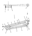
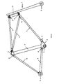
- Figures 1 and 2 illustrate a bicycle frame 1, which is provided with a pedal hub connection part 2, a frame column part 3, a back fork part 4" and a foldable and openable head tube connection part 5, the parts having been connected to each other with folding joints 8.
- the folding joints 8 are preferably cone joints.
- the frame parts 2, 3, 4, 5, 6 are foldable at least in part essentially in the direction of the second frame part 2, 3, 4, 5 and/or at least partly superimposed and/or interlocked.
- the bicycle frame 1 has several support parts 6 for supporting the other frame parts 2, 3, 4, 5.
- the support parts 6 are connected to the back fork part 4 and the connection bars 5 of the front fork also with ball joints 18.
- Figures 1 and 2 additionally show the bicycle frame 1 with an openable head tube connection part 5, at the end of which there is provided a head tube connection element 21, to which the head tube 7P of the front fork 7 has been connected in an non-turning manner, the head tube having a flexible bearing housing 9 for connecting the head tube 7P and the connection part 5 rotatably to each other.
- the front fork 7 has been attached to the bicycle frame 1, the front fork including flexible bearing housings 9 for attaching the front wheel (not shown).
- the bicycle frame 1 shown in Figures 1 and 2 has advantageously two foldable back fork parts 4, which are attached to each other and which have a flexible bearing housing 9 for fastening the back wheel (not shown).
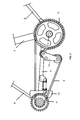
- Figure 3 there is shown an upper/lower gear shifter 13 for shifting the chain K up and down in the wheel packages 11, 12 and a separate chain tightening part 14 at a distance from the gear shifter 13.
- Figure 3 also discloses a pedal hub connection part 2, a frame column part 3, a back fork part 4, and a foldable and openable head tube connection part 5.
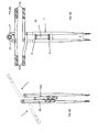
- Figure 4 discloses a pedal hub connection part 2, which has a flexible bearing housing 0 for connecting the pedal hub wheels 16.
- the pedal hub wheels 16 have one foldable pedal crank 17 and front wheel package 12.
- Figure 4 also illustrates a back wheel package 11 and chains K, and a back fork part 4 and an openable head tube connection part 5, which have been connected to the pedal hub connection part with cone joints 8.
- FIG. 5 there is shown a back fork part 4, which has external back wheel package 11 with a free wheel.
- the back fork part 4 has a detachable connection axle 11A for the back wheel, with a slot joint and a spiral joint for joining the back wheel package to the wheel hub.
- connection piece 11L for joining the back wheel package to the back wheel bearing 19 in the flexible bearing housing 9.
- Figure 6A illustrates a front fork 7, which has foldable handlebars 15R and 15L as folded.
- Figures 6B and 6C illustrate the front fork 7, which has foldable handlebars 15B and 15L folded in the open/riding position.
- Figures 6A and 6B further show the flexible bearing housing 9 connected to the front fork 7 for connecting the front wheel (not shown).
- the figure also shows the front fork head tube 7P, which is connected to the front fork by flexible bearing housings 9.
- the flexible bearing housings have bearings (not shown), on which the front fork part 7N can rotate in relation to the head tube 7P.
- the bicycle frame 1 has a front fork 7 with a head tube 7P, which is connected to the fork part 7N of the head tube 7P by flexible bearing housings 9.
- the flexible bearing housings 9 have guide bearings 19, on which the other parts of the front fork 7 can rotate in relation to the head tube 7P.
- the head tube 7P has two nested pipes, which lock the guide bearings 19 to the head tube.
- the figure also shows two openable head tube connection parts 5 with head tube connection elements 21, to which the head tube 7P has been unrotatably attached by a pipe shaft 20.
- the lower connection part 5 of the front fork has further been connected to the support part 6 by a ball joint.
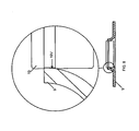
- Figure 8 is a detailed view of a flexible bearing housing 9, to which a bearing 19 has been fastened, with the connecting slot 19V acting as an adapter stop.
- Figure 9 is a detailed view of a cone joint 8.
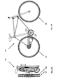
- FIG 10A there is shown the bicycle PP folded to the transport/storage condition, and in Figure 10B it is shown assembled to the working order.
- the back wheel 10T and the front wheel 10E are advantageously structurally uniform with each other, i.e. in this case they also are advantageously interchangeable. Also the shafts of the back wheel 10T and the front wheel 10E are especially narrow so that they can easily be transported e.g. side by side.
- Figure 11 illustrates the front fork locking element 7L for locking the position of the front fork 7.
- An openable connection part 5 has been connected to the front fork, the part having a head tube connection element 21, to which the front fork 7 has been attached.
- the locking element 7L has a locking tongue 7B, which prevents the rotation of the front fork 7.
- the locking element 7L is provided with a locking key 7K, with which the position of the locking tongue can be locked to the closed/open position.
- Figures 12A-12C show the bicycle frame 1 with a pedal hub connection part 2, frame column part 3, back fork part 4, and two foldable and openable head tube connection parts 5, and two foldable support parts 6.
- the support part 6 has first been folded onto the frame column part 3, and the first openable head tube connection part 5 has been folded onto this so that the head tube connection element 21 is set to the mounting opening 5A in the second openable connection part 5 of the head tube upon folding.
- the second head tube connection part 5 is folded onto the first openable connection part 5 of the head tube.
- Figure 12C shows the bicycle frame 1 after folding.
- the back fork part 4 and the support part 6 for the back fork part are turned to the side of the frame column part 3 opposite to the two openable head tube connection parts 5 and support parts 6 for the connection part 5.
Landscapes
- Engineering & Computer Science (AREA)
- Mechanical Engineering (AREA)
- Motorcycle And Bicycle Frame (AREA)
Claims (15)
- Fahrradrahmen mit einem Pedalnabenverbindungsteil (2) und Rahmensäulenteil (3), wobei der Fahrradrahmen (1) eine eigene Vorderradgabel (7) mit einem Steuerrohr (7P) und mit einem oder mehreren öffenbaren Steuerrohrverbindungsteilen (5) zum betriebsfähigem Verbinden der Vorderradgabel (7) aufweist und wobei der öffenbare Steuerrohrverbindungsteil (5) ein nicht drehbares Verbindungselement (21) zum nicht drehbaren Verbinden des Steuerrohrs (7P) der Vorderradgabel (7) aufweist und wobei das Steuerrohr (7P) einen Lageraufbau (19) zum drehbaren Verbinden der Vorderradgabel (7) und des Steuerrohrs (7P) miteinander aufweist, dadurch gekennzeichnet, dass das Vorderradgabelsteuerrohr (7P) mit dem Lageraufbau (19) von der Innenseite aus verbunden ist.
- Fahrradrahmen nach Anspruch 1, dadurch gekennzeichnet, dass der Fahrradrahmen (1) einen oder mehrere Rahmenteile (2, 3, 4, 5, 6) aufweist, welche miteinander (2, 3, 4, 5, 6) entweder direkt oder indirekt durch eine Klappverbindung (8) wie ein Klappgelenk verbunden sind.
- Fahrradrahmen nach jedem beliebigen der Ansprüche 1-2, dadurch gekennzeichnet, dass die Klappverbindung (8) ein Kegelgelenk ist.
- Fahrradrahmen nach den Ansprüchen 2 oder 3, dadurch gekennzeichnet, dass der Rahmenteil (2, 3, 4, 5, 6) in Bezug zu dem anderen Rahmenteil wenigstens teilweise in einer ineinander verriegelten Weise zum Zusammenklappen des Fahrradrahmens (1) zusammengeklappt werden kann.
- Fahrradrahmen nach Anspruch 2, dadurch gekennzeichnet, dass der Fahrradrahmen (1) einen oder mehrere zurückklappbare Gabelteile (4) aufweist.
- Fahrradrahmen nach Anspruch 5, dadurch gekennzeichnet, dass der zurückklappbare Gabelteil (4) ein äußeres Hinterradpaket (11) mit einem Freilauf aufweist.
- Fahrradrahmen nach Anspruch 2, dadurch gekennzeichnet, dass der Fahrradrahmen (1) einen oder mehrere klappbare Trageteile (6) aufweist.
- Fahrradrahmen nach einem beliebigen der vorangehenden Ansprüche, dadurch gekennzeichnet, dass der Fahrradrahmen (1) eines oder mehrere bewegliche Lagergehäuse (9) aufweist.
- Fahrradrahmen nach einem beliebigen der vorangehenden Ansprüche, dadurch gekennzeichnet, dass der Fahrradrahmen (1) eines oder mehrere bewegliche Lagergehäuse (9) aufweist, wobei deren Beweglichkeit wenigstens gleich zum Adapteranschlag (19V) des Lagers (19) geht, welches im Lagergehäuse (9) eingepasst wird.
- Fahrradrahmen nach einem beliebigen der vorangehenden Ansprüche, dadurch gekennzeichnet, dass das Steuerrohr (7P) mit dem Gabelteil (7N) durch bewegliche Lagergehäuse (9), welche den Lageraufbau (19) aufweisen, verbunden worden ist.
- Fahrradrahmen nach einem beliebigen der vorangehenden Ansprüche, dadurch gekennzeichnet, dass eine Vorderradgabel (7) mit dem Fahrradrahmen (1) verbunden worden ist, wobei die Vorderradgabel klappbare Lenkstangen (15L, 15R) aufweist, wie die Lenkstangen (15L), um in die Richtung der Vorderradgabel geklappt zu werden, oder wie die Lenkstangen (15R), welche offen in einer miteinander verriegelten/darübergelegten Weise in Bezug aufeinander zusammengeklappt werden können.
- Fahrradrahmen nach einem beliebigen der vorangehenden Ansprüche, dadurch gekennzeichnet, dass der Fahrradrahmen (1) ein Vorderradgabelverriegelungselement (7L) zum Verriegeln der Position der Vorderradgabel (7) aufweist.
- Fahrrad, Trainingsfahrrad wie ein Testfahrrad, Handfahrrad und/oder Liegefahrrad, dadurch gekennzeichnet, dass es einen Fahrradrahmen (1) nach einem beliebigen der Ansprüche 1 bis 12 aufweist.
- Bausatz zum Zusammenbauen eines Fahrrads nach Anspruch 13.
- Verfahren zur Herstellung eines Fahrradrahmens mit einem Pedalnabenverbindungsteil (2) und Rahmensäulenteil (3), wobei eine Vorderradgabel (7) mit einem Steuerrohr (7P) und einem öffenbaren Steuerrohrverbindungsteil (5) an einem Fahrradrahmen (1) zum öffenbaren Verbinden der Vorderradgabel (7) angeordnet sind, wobei der öffenbare Steuerrohrverbindungsteil (5) mit einem nicht drehbaren Verbindungselement (21) zum nicht drehbaren Verbinden des Steuerrohrs (7P) der Vorderradgabel (7) vorgesehen ist und das Steuerrohr (7P) mit einem Lageraufbau (19) zum drehbaren Verbinden der Vorderradgabel (7) und des Steuerrohrs (7P) miteinander vorgesehen ist, dadurch gekennzeichnet, dass das Vorderradgabelsteuerrohr (7P) mit dem Lageraufbau (19) von der Innenseite aus verbunden ist.
Applications Claiming Priority (2)
| Application Number | Priority Date | Filing Date | Title |
|---|---|---|---|
| FI20070192A FI20070192A0 (fi) | 2007-03-06 | 2007-03-06 | Pyörän runko ja pyörä |
| PCT/FI2008/050105 WO2008107521A1 (en) | 2007-03-06 | 2008-03-06 | Bicycle frame and bicycle |
Publications (3)
| Publication Number | Publication Date |
|---|---|
| EP2114758A1 EP2114758A1 (de) | 2009-11-11 |
| EP2114758A4 EP2114758A4 (de) | 2011-08-24 |
| EP2114758B1 true EP2114758B1 (de) | 2013-01-23 |
Family
ID=37929997
Family Applications (1)
| Application Number | Title | Priority Date | Filing Date |
|---|---|---|---|
| EP08718558A Not-in-force EP2114758B1 (de) | 2007-03-06 | 2008-03-06 | Fahrradrahmen und fahrrad |
Country Status (6)
| Country | Link |
|---|---|
| US (1) | US8328219B2 (de) |
| EP (1) | EP2114758B1 (de) |
| JP (1) | JP2010520114A (de) |
| CN (1) | CN101715406B (de) |
| FI (1) | FI20070192A0 (de) |
| WO (1) | WO2008107521A1 (de) |
Cited By (1)
| Publication number | Priority date | Publication date | Assignee | Title |
|---|---|---|---|---|
| WO2018211104A1 (fr) | 2017-05-19 | 2018-11-22 | Gilles Henry | Velo pliant |
Families Citing this family (11)
| Publication number | Priority date | Publication date | Assignee | Title |
|---|---|---|---|---|
| WO2010025544A1 (en) * | 2008-09-04 | 2010-03-11 | Cycles Argon-18 Inc. | Adjustable cycle steering headset |
| KR100981059B1 (ko) * | 2010-02-09 | 2010-09-08 | 윤근수 | 접철식 자전거 |
| EP2409906A3 (de) * | 2010-07-21 | 2013-09-25 | Georg Mies | Faltrad |
| US8789840B2 (en) * | 2012-09-19 | 2014-07-29 | Richard Priest | Folding bicycle and method of use |
| CN103963897A (zh) * | 2014-05-06 | 2014-08-06 | 王民海 | 一种前叉和车身的连接 |
| CN105480342B (zh) * | 2016-01-19 | 2018-03-02 | 嘉兴小虎子车业有限公司 | 可折叠的儿童三轮车及其折叠方法 |
| FI20165774A (fi) * | 2016-10-12 | 2018-04-13 | Laxstroem Zakarias | Polkupyörä |
| US10328992B2 (en) * | 2016-10-12 | 2019-06-25 | Zakarias LAXSTRÖM | Bicycle |
| US10556464B2 (en) | 2018-01-21 | 2020-02-11 | Bert Vermeulen | Spoked human-powerable vehicle wheel with user-removable hub and plurality of conical hub-to-annulus attachment elements |
| CN110606158A (zh) * | 2018-06-14 | 2019-12-24 | 天津市耐嘛科技有限公司 | 一种方便安装的组合式自行车车架 |
| US12623747B2 (en) * | 2022-07-10 | 2026-05-12 | Bert Vermeulen | Systems and methods for folding and packing a human powerable vehicle |
Family Cites Families (22)
| Publication number | Priority date | Publication date | Assignee | Title |
|---|---|---|---|---|
| CA963034A (en) * | 1972-10-26 | 1975-02-18 | Gary A. Robison | Motorcycle steering head angle adjustment |
| JPS50111840U (de) * | 1974-02-19 | 1975-09-11 | ||
| US4129317A (en) * | 1976-03-05 | 1978-12-12 | Bell Theodore F | Bicycle |
| US4440414A (en) * | 1979-12-17 | 1984-04-03 | Wang Fu Chow | Foldable bicycle |
| US4462606A (en) * | 1981-02-12 | 1984-07-31 | Hon Corporation International | Foldable and portable vehicle |
| JPS57147975A (en) * | 1981-03-09 | 1982-09-13 | Bridgestone Cycle Co | Frame for two-wheel barrow |
| US4600207A (en) * | 1982-09-27 | 1986-07-15 | Bernd Grohe | Connection of steering column to frame |
| US4700963A (en) * | 1986-07-21 | 1987-10-20 | Steve Burns | Variable angle steering system |
| DE3701803A1 (de) | 1987-01-22 | 1988-08-04 | Ulrich Bogen | Faltbares zweiraedriges fahrrad |
| JPH02121391U (de) * | 1988-11-17 | 1990-10-02 | ||
| US5069468A (en) * | 1990-08-14 | 1991-12-03 | Tsai Shu Huey | Collapsible bicycle |
| US5383676A (en) * | 1993-09-02 | 1995-01-24 | Valentino; Thomas J. | Centering apparatus for front wheel of three wheeled vehicle |
| GB2289874A (en) * | 1994-01-28 | 1995-12-06 | Malcolm Graham Parry | Folding bicycle |
| IT1299007B1 (it) * | 1998-04-02 | 2000-02-07 | Francesco Mombelli | Bicicletta compattabile nel volume delle due ruote affiancate |
| TW477326U (en) * | 1998-11-06 | 2002-02-21 | Tactic Bike Company Ltd | Bicycle adjustable in size, folding bicycle, clip for folding bicycle, clamp for folding bicycle, seat or handlebar post for adjustable bicycle, bicycle frame, and the container used therefore |
| JP2003506253A (ja) * | 1999-07-30 | 2003-02-18 | パシフィック 21 ピーティーワイ リミテッド | 折りたたみ式自転車用フレーム |
| CN2468885Y (zh) * | 2001-04-06 | 2002-01-02 | 许宪章 | 多用折叠自行车 |
| AUPR773201A0 (en) * | 2001-09-17 | 2001-10-11 | Acedeal Pty Ltd | Pedalling apparatus |
| JP4596891B2 (ja) * | 2004-11-17 | 2010-12-15 | 三洋電機株式会社 | 電動歯ブラシ |
| EP1757518A1 (de) * | 2005-08-24 | 2007-02-28 | Liang-Fong Pan | Klappfahrrad |
| FR2894929B1 (fr) | 2005-12-21 | 2009-07-17 | Cycles Lapierre Soc Par Action | Velo pliable |
| US7438306B2 (en) * | 2006-10-27 | 2008-10-21 | Matthew Mrdeza | Motorcycle rake and trail adjuster |
-
2007
- 2007-03-06 FI FI20070192A patent/FI20070192A0/fi not_active Application Discontinuation
-
2008
- 2008-03-06 EP EP08718558A patent/EP2114758B1/de not_active Not-in-force
- 2008-03-06 WO PCT/FI2008/050105 patent/WO2008107521A1/en not_active Ceased
- 2008-03-06 US US12/530,399 patent/US8328219B2/en not_active Expired - Fee Related
- 2008-03-06 CN CN200880012151.1A patent/CN101715406B/zh not_active Expired - Fee Related
- 2008-03-06 JP JP2009552236A patent/JP2010520114A/ja active Pending
Cited By (2)
| Publication number | Priority date | Publication date | Assignee | Title |
|---|---|---|---|---|
| WO2018211104A1 (fr) | 2017-05-19 | 2018-11-22 | Gilles Henry | Velo pliant |
| US11242109B2 (en) | 2017-05-19 | 2022-02-08 | Gilles Henry | Folding bicycle |
Also Published As
| Publication number | Publication date |
|---|---|
| US8328219B2 (en) | 2012-12-11 |
| EP2114758A1 (de) | 2009-11-11 |
| FI20070192A0 (fi) | 2007-03-06 |
| JP2010520114A (ja) | 2010-06-10 |
| CN101715406B (zh) | 2013-07-17 |
| CN101715406A (zh) | 2010-05-26 |
| WO2008107521A1 (en) | 2008-09-12 |
| EP2114758A4 (de) | 2011-08-24 |
| US20100066055A1 (en) | 2010-03-18 |
Similar Documents
| Publication | Publication Date | Title |
|---|---|---|
| US8328219B2 (en) | Bicycle frame and bicycle | |
| EP1053168B1 (de) | Zweirad mit zusammenklappbarem rahmen mit betätigungskontrolle und übertragungsvorrichtung | |
| US3990717A (en) | Collapsible vehicle | |
| US20100066054A1 (en) | Collapsible bicycle | |
| US20060082097A1 (en) | Convertible riding toy | |
| WO2011103656A1 (en) | Modular recumbent vehicle | |
| CN106904235A (zh) | 一种折叠车 | |
| US8523210B1 (en) | Combination buddy bicycle | |
| CN101559810B (zh) | 便携式四轮踏溜车 | |
| WO2012034158A1 (en) | Folding diamond type frame for a bicycle | |
| WO2004096630A1 (en) | Human-powered vehicle | |
| EP3752413B1 (de) | Zweirädriges fahrrad mit variabler konfiguration | |
| EP2803565A1 (de) | Antriebsgetriebegruppe an einem Lenkrad eines Fahrzeugs | |
| CN107933790B (zh) | 自行车 | |
| US20060125205A1 (en) | Front wheel drive mechanism for bicycle | |
| US20170021891A1 (en) | Stressed fork motorcycle reverse trike conversion apparatus | |
| US7121567B1 (en) | Bicycle having front and rear rotative wheel frames with actuatable means for engaging and disengaging the rear wheel frame rotation | |
| CN207274864U (zh) | 一种能拆组成滑步车的自行车 | |
| CN220786015U (zh) | 一种多功能组合变形倒三轮自行车 | |
| CN102190042B (zh) | 自锁式折叠自行车 | |
| CN219904630U (zh) | 一种转向回位系统 | |
| CN102173307B (zh) | 前驱后舵式脚踏车 | |
| TW201341256A (zh) | 多人相乘車 | |
| CN102602487A (zh) | 前两轮可折叠式三轮自行车 | |
| CN209833874U (zh) | 自行车折收机构 |
Legal Events
| Date | Code | Title | Description |
|---|---|---|---|
| PUAI | Public reference made under article 153(3) epc to a published international application that has entered the european phase |
Free format text: ORIGINAL CODE: 0009012 |
|
| 17P | Request for examination filed |
Effective date: 20090831 |
|
| AK | Designated contracting states |
Kind code of ref document: A1 Designated state(s): AT BE BG CH CY CZ DE DK EE ES FI FR GB GR HR HU IE IS IT LI LT LU LV MC MT NL NO PL PT RO SE SI SK TR |
|
| DAX | Request for extension of the european patent (deleted) | ||
| A4 | Supplementary search report drawn up and despatched |
Effective date: 20110727 |
|
| RIC1 | Information provided on ipc code assigned before grant |
Ipc: B62K 15/00 20060101AFI20110721BHEP Ipc: B62K 21/06 20060101ALI20110721BHEP |
|
| RAP1 | Party data changed (applicant data changed or rights of an application transferred) |
Owner name: FUBICOM AB OY |
|
| RIN1 | Information on inventor provided before grant (corrected) |
Inventor name: LAXSTROEM, ULF |
|
| GRAP | Despatch of communication of intention to grant a patent |
Free format text: ORIGINAL CODE: EPIDOSNIGR1 |
|
| GRAS | Grant fee paid |
Free format text: ORIGINAL CODE: EPIDOSNIGR3 |
|
| GRAA | (expected) grant |
Free format text: ORIGINAL CODE: 0009210 |
|
| AK | Designated contracting states |
Kind code of ref document: B1 Designated state(s): AT BE BG CH CY CZ DE DK EE ES FI FR GB GR HR HU IE IS IT LI LT LU LV MC MT NL NO PL PT RO SE SI SK TR |
|
| REG | Reference to a national code |
Ref country code: GB Ref legal event code: FG4D |
|
| REG | Reference to a national code |
Ref country code: CH Ref legal event code: EP |
|
| REG | Reference to a national code |
Ref country code: AT Ref legal event code: REF Ref document number: 594793 Country of ref document: AT Kind code of ref document: T Effective date: 20130215 Ref country code: CH Ref legal event code: EP |
|
| REG | Reference to a national code |
Ref country code: IE Ref legal event code: FG4D |
|
| REG | Reference to a national code |
Ref country code: DE Ref legal event code: R096 Ref document number: 602008021848 Country of ref document: DE Effective date: 20130321 |
|
| PGFP | Annual fee paid to national office [announced via postgrant information from national office to epo] |
Ref country code: NL Payment date: 20130325 Year of fee payment: 6 |
|
| REG | Reference to a national code |
Ref country code: AT Ref legal event code: MK05 Ref document number: 594793 Country of ref document: AT Kind code of ref document: T Effective date: 20130123 |
|
| REG | Reference to a national code |
Ref country code: LT Ref legal event code: MG4D |
|
| REG | Reference to a national code |
Ref country code: NL Ref legal event code: VDEP Effective date: 20130123 |
|
| PG25 | Lapsed in a contracting state [announced via postgrant information from national office to epo] |
Ref country code: BG Free format text: LAPSE BECAUSE OF FAILURE TO SUBMIT A TRANSLATION OF THE DESCRIPTION OR TO PAY THE FEE WITHIN THE PRESCRIBED TIME-LIMIT Effective date: 20130423 Ref country code: ES Free format text: LAPSE BECAUSE OF FAILURE TO SUBMIT A TRANSLATION OF THE DESCRIPTION OR TO PAY THE FEE WITHIN THE PRESCRIBED TIME-LIMIT Effective date: 20130504 Ref country code: IS Free format text: LAPSE BECAUSE OF FAILURE TO SUBMIT A TRANSLATION OF THE DESCRIPTION OR TO PAY THE FEE WITHIN THE PRESCRIBED TIME-LIMIT Effective date: 20130523 Ref country code: AT Free format text: LAPSE BECAUSE OF FAILURE TO SUBMIT A TRANSLATION OF THE DESCRIPTION OR TO PAY THE FEE WITHIN THE PRESCRIBED TIME-LIMIT Effective date: 20130123 Ref country code: LT Free format text: LAPSE BECAUSE OF FAILURE TO SUBMIT A TRANSLATION OF THE DESCRIPTION OR TO PAY THE FEE WITHIN THE PRESCRIBED TIME-LIMIT Effective date: 20130123 Ref country code: NO Free format text: LAPSE BECAUSE OF FAILURE TO SUBMIT A TRANSLATION OF THE DESCRIPTION OR TO PAY THE FEE WITHIN THE PRESCRIBED TIME-LIMIT Effective date: 20130423 Ref country code: SE Free format text: LAPSE BECAUSE OF FAILURE TO SUBMIT A TRANSLATION OF THE DESCRIPTION OR TO PAY THE FEE WITHIN THE PRESCRIBED TIME-LIMIT Effective date: 20130123 Ref country code: BE Free format text: LAPSE BECAUSE OF FAILURE TO SUBMIT A TRANSLATION OF THE DESCRIPTION OR TO PAY THE FEE WITHIN THE PRESCRIBED TIME-LIMIT Effective date: 20130123 |
|
| PG25 | Lapsed in a contracting state [announced via postgrant information from national office to epo] |
Ref country code: SI Free format text: LAPSE BECAUSE OF FAILURE TO SUBMIT A TRANSLATION OF THE DESCRIPTION OR TO PAY THE FEE WITHIN THE PRESCRIBED TIME-LIMIT Effective date: 20130123 Ref country code: GR Free format text: LAPSE BECAUSE OF FAILURE TO SUBMIT A TRANSLATION OF THE DESCRIPTION OR TO PAY THE FEE WITHIN THE PRESCRIBED TIME-LIMIT Effective date: 20130424 Ref country code: FI Free format text: LAPSE BECAUSE OF FAILURE TO SUBMIT A TRANSLATION OF THE DESCRIPTION OR TO PAY THE FEE WITHIN THE PRESCRIBED TIME-LIMIT Effective date: 20130123 Ref country code: PL Free format text: LAPSE BECAUSE OF FAILURE TO SUBMIT A TRANSLATION OF THE DESCRIPTION OR TO PAY THE FEE WITHIN THE PRESCRIBED TIME-LIMIT Effective date: 20130123 Ref country code: NL Free format text: LAPSE BECAUSE OF FAILURE TO SUBMIT A TRANSLATION OF THE DESCRIPTION OR TO PAY THE FEE WITHIN THE PRESCRIBED TIME-LIMIT Effective date: 20130123 Ref country code: PT Free format text: LAPSE BECAUSE OF FAILURE TO SUBMIT A TRANSLATION OF THE DESCRIPTION OR TO PAY THE FEE WITHIN THE PRESCRIBED TIME-LIMIT Effective date: 20130523 Ref country code: LV Free format text: LAPSE BECAUSE OF FAILURE TO SUBMIT A TRANSLATION OF THE DESCRIPTION OR TO PAY THE FEE WITHIN THE PRESCRIBED TIME-LIMIT Effective date: 20130123 |
|
| PG25 | Lapsed in a contracting state [announced via postgrant information from national office to epo] |
Ref country code: HR Free format text: LAPSE BECAUSE OF FAILURE TO SUBMIT A TRANSLATION OF THE DESCRIPTION OR TO PAY THE FEE WITHIN THE PRESCRIBED TIME-LIMIT Effective date: 20130123 |
|
| PG25 | Lapsed in a contracting state [announced via postgrant information from national office to epo] |
Ref country code: MC Free format text: LAPSE BECAUSE OF NON-PAYMENT OF DUE FEES Effective date: 20130331 Ref country code: DK Free format text: LAPSE BECAUSE OF FAILURE TO SUBMIT A TRANSLATION OF THE DESCRIPTION OR TO PAY THE FEE WITHIN THE PRESCRIBED TIME-LIMIT Effective date: 20130123 Ref country code: EE Free format text: LAPSE BECAUSE OF FAILURE TO SUBMIT A TRANSLATION OF THE DESCRIPTION OR TO PAY THE FEE WITHIN THE PRESCRIBED TIME-LIMIT Effective date: 20130123 Ref country code: SK Free format text: LAPSE BECAUSE OF FAILURE TO SUBMIT A TRANSLATION OF THE DESCRIPTION OR TO PAY THE FEE WITHIN THE PRESCRIBED TIME-LIMIT Effective date: 20130123 Ref country code: RO Free format text: LAPSE BECAUSE OF FAILURE TO SUBMIT A TRANSLATION OF THE DESCRIPTION OR TO PAY THE FEE WITHIN THE PRESCRIBED TIME-LIMIT Effective date: 20130123 Ref country code: CZ Free format text: LAPSE BECAUSE OF FAILURE TO SUBMIT A TRANSLATION OF THE DESCRIPTION OR TO PAY THE FEE WITHIN THE PRESCRIBED TIME-LIMIT Effective date: 20130123 |
|
| REG | Reference to a national code |
Ref country code: CH Ref legal event code: PL |
|
| PG25 | Lapsed in a contracting state [announced via postgrant information from national office to epo] |
Ref country code: CY Free format text: LAPSE BECAUSE OF FAILURE TO SUBMIT A TRANSLATION OF THE DESCRIPTION OR TO PAY THE FEE WITHIN THE PRESCRIBED TIME-LIMIT Effective date: 20130123 |
|
| PLBE | No opposition filed within time limit |
Free format text: ORIGINAL CODE: 0009261 |
|
| STAA | Information on the status of an ep patent application or granted ep patent |
Free format text: STATUS: NO OPPOSITION FILED WITHIN TIME LIMIT |
|
| PG25 | Lapsed in a contracting state [announced via postgrant information from national office to epo] |
Ref country code: IT Free format text: LAPSE BECAUSE OF FAILURE TO SUBMIT A TRANSLATION OF THE DESCRIPTION OR TO PAY THE FEE WITHIN THE PRESCRIBED TIME-LIMIT Effective date: 20130123 |
|
| 26N | No opposition filed |
Effective date: 20131024 |
|
| REG | Reference to a national code |
Ref country code: IE Ref legal event code: MM4A |
|
| PG25 | Lapsed in a contracting state [announced via postgrant information from national office to epo] |
Ref country code: LI Free format text: LAPSE BECAUSE OF NON-PAYMENT OF DUE FEES Effective date: 20130331 Ref country code: CH Free format text: LAPSE BECAUSE OF NON-PAYMENT OF DUE FEES Effective date: 20130331 Ref country code: IE Free format text: LAPSE BECAUSE OF NON-PAYMENT OF DUE FEES Effective date: 20130306 |
|
| REG | Reference to a national code |
Ref country code: DE Ref legal event code: R097 Ref document number: 602008021848 Country of ref document: DE Effective date: 20131024 |
|
| PG25 | Lapsed in a contracting state [announced via postgrant information from national office to epo] |
Ref country code: MT Free format text: LAPSE BECAUSE OF FAILURE TO SUBMIT A TRANSLATION OF THE DESCRIPTION OR TO PAY THE FEE WITHIN THE PRESCRIBED TIME-LIMIT Effective date: 20130123 |
|
| PG25 | Lapsed in a contracting state [announced via postgrant information from national office to epo] |
Ref country code: TR Free format text: LAPSE BECAUSE OF FAILURE TO SUBMIT A TRANSLATION OF THE DESCRIPTION OR TO PAY THE FEE WITHIN THE PRESCRIBED TIME-LIMIT Effective date: 20130123 |
|
| PG25 | Lapsed in a contracting state [announced via postgrant information from national office to epo] |
Ref country code: HU Free format text: LAPSE BECAUSE OF FAILURE TO SUBMIT A TRANSLATION OF THE DESCRIPTION OR TO PAY THE FEE WITHIN THE PRESCRIBED TIME-LIMIT; INVALID AB INITIO Effective date: 20080306 Ref country code: LU Free format text: LAPSE BECAUSE OF NON-PAYMENT OF DUE FEES Effective date: 20130306 |
|
| REG | Reference to a national code |
Ref country code: FR Ref legal event code: PLFP Year of fee payment: 9 |
|
| REG | Reference to a national code |
Ref country code: FR Ref legal event code: PLFP Year of fee payment: 10 |
|
| REG | Reference to a national code |
Ref country code: FR Ref legal event code: PLFP Year of fee payment: 11 |
|
| PGFP | Annual fee paid to national office [announced via postgrant information from national office to epo] |
Ref country code: GB Payment date: 20220316 Year of fee payment: 15 Ref country code: DE Payment date: 20220307 Year of fee payment: 15 |
|
| PGFP | Annual fee paid to national office [announced via postgrant information from national office to epo] |
Ref country code: FR Payment date: 20220331 Year of fee payment: 15 |
|
| REG | Reference to a national code |
Ref country code: DE Ref legal event code: R119 Ref document number: 602008021848 Country of ref document: DE |
|
| GBPC | Gb: european patent ceased through non-payment of renewal fee |
Effective date: 20230306 |
|
| PG25 | Lapsed in a contracting state [announced via postgrant information from national office to epo] |
Ref country code: GB Free format text: LAPSE BECAUSE OF NON-PAYMENT OF DUE FEES Effective date: 20230306 |
|
| PG25 | Lapsed in a contracting state [announced via postgrant information from national office to epo] |
Ref country code: GB Free format text: LAPSE BECAUSE OF NON-PAYMENT OF DUE FEES Effective date: 20230306 Ref country code: FR Free format text: LAPSE BECAUSE OF NON-PAYMENT OF DUE FEES Effective date: 20230331 Ref country code: DE Free format text: LAPSE BECAUSE OF NON-PAYMENT OF DUE FEES Effective date: 20231003 |