EP2113973A1 - Laser source and method for generating millimeter wave - Google Patents
Laser source and method for generating millimeter wave Download PDFInfo
- Publication number
- EP2113973A1 EP2113973A1 EP08305135A EP08305135A EP2113973A1 EP 2113973 A1 EP2113973 A1 EP 2113973A1 EP 08305135 A EP08305135 A EP 08305135A EP 08305135 A EP08305135 A EP 08305135A EP 2113973 A1 EP2113973 A1 EP 2113973A1
- Authority
- EP
- European Patent Office
- Prior art keywords
- laser
- sections
- laser sections
- laser source
- injection current
- Prior art date
- Legal status (The legal status is an assumption and is not a legal conclusion. Google has not performed a legal analysis and makes no representation as to the accuracy of the status listed.)
- Withdrawn
Links
Images


Classifications
-
- H—ELECTRICITY
- H01—ELECTRIC ELEMENTS
- H01S—DEVICES USING THE PROCESS OF LIGHT AMPLIFICATION BY STIMULATED EMISSION OF RADIATION [LASER] TO AMPLIFY OR GENERATE LIGHT; DEVICES USING STIMULATED EMISSION OF ELECTROMAGNETIC RADIATION IN WAVE RANGES OTHER THAN OPTICAL
- H01S5/00—Semiconductor lasers
- H01S5/10—Construction or shape of the optical resonator, e.g. extended or external cavity, coupled cavities, bent-guide, varying width, thickness or composition of the active region
- H01S5/12—Construction or shape of the optical resonator, e.g. extended or external cavity, coupled cavities, bent-guide, varying width, thickness or composition of the active region the resonator having a periodic structure, e.g. in distributed feedback [DFB] lasers
-
- H—ELECTRICITY
- H01—ELECTRIC ELEMENTS
- H01S—DEVICES USING THE PROCESS OF LIGHT AMPLIFICATION BY STIMULATED EMISSION OF RADIATION [LASER] TO AMPLIFY OR GENERATE LIGHT; DEVICES USING STIMULATED EMISSION OF ELECTROMAGNETIC RADIATION IN WAVE RANGES OTHER THAN OPTICAL
- H01S1/00—Masers, i.e. devices using stimulated emission of electromagnetic radiation in the microwave range
- H01S1/02—Masers, i.e. devices using stimulated emission of electromagnetic radiation in the microwave range solid
-
- H—ELECTRICITY
- H01—ELECTRIC ELEMENTS
- H01S—DEVICES USING THE PROCESS OF LIGHT AMPLIFICATION BY STIMULATED EMISSION OF RADIATION [LASER] TO AMPLIFY OR GENERATE LIGHT; DEVICES USING STIMULATED EMISSION OF ELECTROMAGNETIC RADIATION IN WAVE RANGES OTHER THAN OPTICAL
- H01S5/00—Semiconductor lasers
- H01S5/06—Arrangements for controlling the laser output parameters, e.g. by operating on the active medium
- H01S5/062—Arrangements for controlling the laser output parameters, e.g. by operating on the active medium by varying the potential of the electrodes
- H01S5/0625—Arrangements for controlling the laser output parameters, e.g. by operating on the active medium by varying the potential of the electrodes in multi-section lasers
- H01S5/06255—Controlling the frequency of the radiation
- H01S5/06258—Controlling the frequency of the radiation with DFB-structure
-
- H—ELECTRICITY
- H01—ELECTRIC ELEMENTS
- H01S—DEVICES USING THE PROCESS OF LIGHT AMPLIFICATION BY STIMULATED EMISSION OF RADIATION [LASER] TO AMPLIFY OR GENERATE LIGHT; DEVICES USING STIMULATED EMISSION OF ELECTROMAGNETIC RADIATION IN WAVE RANGES OTHER THAN OPTICAL
- H01S5/00—Semiconductor lasers
- H01S5/06—Arrangements for controlling the laser output parameters, e.g. by operating on the active medium
- H01S5/0604—Arrangements for controlling the laser output parameters, e.g. by operating on the active medium comprising a non-linear region, e.g. generating harmonics of the laser frequency
-
- H—ELECTRICITY
- H01—ELECTRIC ELEMENTS
- H01S—DEVICES USING THE PROCESS OF LIGHT AMPLIFICATION BY STIMULATED EMISSION OF RADIATION [LASER] TO AMPLIFY OR GENERATE LIGHT; DEVICES USING STIMULATED EMISSION OF ELECTROMAGNETIC RADIATION IN WAVE RANGES OTHER THAN OPTICAL
- H01S5/00—Semiconductor lasers
- H01S5/06—Arrangements for controlling the laser output parameters, e.g. by operating on the active medium
- H01S5/0607—Arrangements for controlling the laser output parameters, e.g. by operating on the active medium by varying physical parameters other than the potential of the electrodes, e.g. by an electric or magnetic field, mechanical deformation, pressure, light, temperature
- H01S5/0612—Arrangements for controlling the laser output parameters, e.g. by operating on the active medium by varying physical parameters other than the potential of the electrodes, e.g. by an electric or magnetic field, mechanical deformation, pressure, light, temperature controlled by temperature
-
- H—ELECTRICITY
- H01—ELECTRIC ELEMENTS
- H01S—DEVICES USING THE PROCESS OF LIGHT AMPLIFICATION BY STIMULATED EMISSION OF RADIATION [LASER] TO AMPLIFY OR GENERATE LIGHT; DEVICES USING STIMULATED EMISSION OF ELECTROMAGNETIC RADIATION IN WAVE RANGES OTHER THAN OPTICAL
- H01S5/00—Semiconductor lasers
- H01S5/06—Arrangements for controlling the laser output parameters, e.g. by operating on the active medium
- H01S5/065—Mode locking; Mode suppression; Mode selection ; Self pulsating
- H01S5/0657—Mode locking, i.e. generation of pulses at a frequency corresponding to a roundtrip in the cavity
-
- H—ELECTRICITY
- H01—ELECTRIC ELEMENTS
- H01S—DEVICES USING THE PROCESS OF LIGHT AMPLIFICATION BY STIMULATED EMISSION OF RADIATION [LASER] TO AMPLIFY OR GENERATE LIGHT; DEVICES USING STIMULATED EMISSION OF ELECTROMAGNETIC RADIATION IN WAVE RANGES OTHER THAN OPTICAL
- H01S5/00—Semiconductor lasers
- H01S5/10—Construction or shape of the optical resonator, e.g. extended or external cavity, coupled cavities, bent-guide, varying width, thickness or composition of the active region
- H01S5/12—Construction or shape of the optical resonator, e.g. extended or external cavity, coupled cavities, bent-guide, varying width, thickness or composition of the active region the resonator having a periodic structure, e.g. in distributed feedback [DFB] lasers
- H01S5/1206—Construction or shape of the optical resonator, e.g. extended or external cavity, coupled cavities, bent-guide, varying width, thickness or composition of the active region the resonator having a periodic structure, e.g. in distributed feedback [DFB] lasers having a non constant or multiplicity of periods
- H01S5/1215—Multiplicity of periods
-
- H—ELECTRICITY
- H01—ELECTRIC ELEMENTS
- H01S—DEVICES USING THE PROCESS OF LIGHT AMPLIFICATION BY STIMULATED EMISSION OF RADIATION [LASER] TO AMPLIFY OR GENERATE LIGHT; DEVICES USING STIMULATED EMISSION OF ELECTROMAGNETIC RADIATION IN WAVE RANGES OTHER THAN OPTICAL
- H01S5/00—Semiconductor lasers
- H01S5/40—Arrangement of two or more semiconductor lasers, not provided for in groups H01S5/02 - H01S5/30
- H01S5/4006—Injection locking
-
- H—ELECTRICITY
- H01—ELECTRIC ELEMENTS
- H01S—DEVICES USING THE PROCESS OF LIGHT AMPLIFICATION BY STIMULATED EMISSION OF RADIATION [LASER] TO AMPLIFY OR GENERATE LIGHT; DEVICES USING STIMULATED EMISSION OF ELECTROMAGNETIC RADIATION IN WAVE RANGES OTHER THAN OPTICAL
- H01S5/00—Semiconductor lasers
- H01S5/40—Arrangement of two or more semiconductor lasers, not provided for in groups H01S5/02 - H01S5/30
- H01S5/4025—Array arrangements, e.g. constituted by discrete laser diodes or laser bar
- H01S5/4087—Array arrangements, e.g. constituted by discrete laser diodes or laser bar emitting more than one wavelength
Definitions
- the present invention relates to the field of laser sources and more particularly of mode-locked laser sources.
- Laser sources allow to produce optical signals with narrow spectral bandwidth thanks to the mode selection achieved by their cavity.
- Mode-locking is a technique used to produce pulses of light of extremely short duration.
- the basis of the technique is to induce a fixed phase relationship between the modes of the laser's resonant cavity.
- the laser is then said to be phase-locked or mode-locked.
- pulses of light of short duration with narrow spectral bandwidth can be produced.
- a dual-mode configuration can be used to create millimeter-wave signal due to the four-wave-mixing effect.
- the shape and chirp of said generated pulses of light can hardly be adjusted and the millimeter-wave signals created by the dual-mode configuration comprise an undesirable phase noise.
- One object of the present invention is to provide a new design and method to allow adjustment of the shape and chirp of short duration light pulses.
- a laser source comprising laser sections wherein at least three laser sections comprise each
- said at least three laser sections are shifted in frequency by a predetermined value with respect to each other, said at least three laser sections are shifted in phase by a predetermined value with respect to each other thereby achieving a control of a simultaneous emission frequency of said at least three sections.
- the predetermined value of the frequency shift between two of said at least three laser sections is in a range from 20 to 100 GHz.
- two laser sections of the at least three laser sections are injected with high intensity currents to produce a four-wave-mixing phenomenon whereas the other sections are injected with lower currents, the values of said lower currents being adjusted in order to control the shape of the generated pulses.
- the injection current value of a laser section is above a lasing threshold value.
- the active layer of the distributed feedback laser is a quantum dot structure or a quantum well structure or a bulk structure.
- said at least three laser sections comprise an adjustable heating device allowing to adjust the instant phase shift of the emitted light.
- said adjustable heating device is a resistance
- a plurality of laser sections comprise each a static phase shift adjustment device and at least one laser section does not comprise a static phase shift adjustment device.
- the present invention offers a method for adjusting the pulse shape and chirp of a laser source, said laser source comprising laser sections wherein at least three laser sections have respective grating periods being different from each other, respective active layers and respective electrodes, the method comprising the steps of
- said at least three laser sections comprise a heating device and said method further comprising the step of
- static phase shifts between laser sections are adjusted in accordance with a geometrical organization of the laser source on a chip.
- static phase shifts are adjusted by static phase shift adjustment devices located on the optical paths.
- said method comprises the following steps of:
- the present invention offers a method for generating millimeter wave using a laser source comprising laser sections wherein at least three laser sections comprise a distributed feedback laser with a Bragg grating having respective grating periods wherein said respective grating periods are different from each other and comprise an active layer and an electrode, wherein an injection current is injected into the electrode, and wherein two laser sections of said at least three laser sections are injected with high intensity currents to produce a four-wave-mixing phenomenon, the other sections being injected by lower intensity currents in order to control the shape of the generated pulses.
- the present invention relates to the use of a multi-section distributed feedback (DFB) laser where each section operates on a single longitudinal mode.
- a multi-section distributed feedback (DFB) laser where each section operates on a single longitudinal mode.
- a laser is represented in Fig.1 .
- Each section comprises a DFB laser source 1 comprising an active layer 3 and a Bragg grating 5.
- the active layer 3 can be bulk, quantum well or preferably quantum dot structure to reduce time jitter.
- the frequency of the signal emitted by a section is determined by the Bragg grating period of said section.
- the frequency difference between two adjacent sections can be adjusted for example between 20 and 100 GHz.
- each section is pumped electrically by an electrode but an alternative solution using optical pumping is possible.
- the value of the injection currents I of each section is set to be above a lasing threshold and are independently adjusted.
- the output emission spectrum therefore consists of plurality of lines with nearly equal wavelength spacing between two neighbor lines.
- this wavelength spacing is not necessarily very precise.
- the emission frequency of each section is accurately controlled.
- a local heating device is designed for each section such that the thermal effect allows to control the phase shift and therefore the emission frequency.
- Said heating device can be, for example, a heating resistance. This implies the introduction of an additional electrode for each DFB section in order to adjust the current to produce the desired temperature and therefore the desired frequency change.
- This initial control can be set to initiate the mode locking described below.
- Another element influencing the generated signal is the static phase shift induced by the difference of optical path (distance) between the different laser beams.
- This static phase shift can be controlled either by the geometrical organization of the different laser sources (integration of laser diodes on a single chip, integrated circuit or wafer) or static phase adjustment devices. These static phase adjustment devices are located on the optical paths of the different laser beams. If the whole system comprises N laser sources, N-1 static phase adjustment devices are needed to obtain a constant phase shift between the different light beams.
- mode-locking is used.
- Two types of mode-locking regimes can be used, either active or passive.
- active case an external modulation is applied and the mode-locking is achieved through the locking of neighbor lines to the modulation side bands whereas in the passive case the mode-locking is achieved through internal nonlinear phenomenon such as four-wave-mixing.
- harmonics can be created that allow to control the shape of the generated pulses.
- dual-mode configuration can be used.
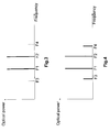
- high intensity currents are applied on two different sections emitting at two different primary frequencies F1 and F2 as presented in Fig.2 .
- deltaF difference in frequency
- F3 and F4 are generated by the nonlinear interaction of the two primary frequencies. These frequencies correspond to F1-deltaF and F2+deltaF and are represented in Fig.3 where the continuous lines represent the injected signals and the dotted lines represent signals generated by four-wave-mixing.
- One embodiment of the present invention proposes the use of at least one additional section at frequency F3 or F4, said additional section being injected by a current with a lower intensity than the F1 and F2 sections injection currents.
- the optical spectrum of such embodiment is shown in Fig.4 where four active sections are used (at frequencies F1, F2, F3 and F4), allowing the control of the amplitude of the harmonics of the millimeter wave. Control of the amplitude of the different frequencies allows to control the phase of the generated pulses and thus reduces the generated phase noise.
- additional harmonics can be generated by interactions between F3 and F1 or F3 and F4 for example so that a higher number of sections could be used to control the shape of the generated pulses.
- E k0 is the amplitude of the k th optical wave
- j is the imaginary constant
- F k is the frequency of the k th optical wave
- t is the time
- ⁇ k is the phase of the k th optical wave
- k is a constant.
- Eq.2 is to control the beating signal given by Eq.2 thanks to physical adjustable parameters, in the case of non ideal mode locking. These parameters are the relative power amplitudes ⁇ k and the frequencies F k of the optical waves of each DFB section.
- ⁇ and ⁇ are real numbers and represent respectively the amplitude modulation and the phase modulation of the beating wave.
- ⁇ F is the instantaneous frequency variation of the beating wave at the instant t.
- Adjustment of the chirp comprises the following setting steps:
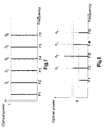
- Fig.5 represents the optical spectrum without any settings in the case of 6 laser diodes.
- ⁇ the relative amplitude of the spectral lines ( ⁇ ) as well as the spacing between said spectral lines are not constant.
- Fig.6 shows the influence of the adjustment of the instant phase shifts on the optical spectrum.
- the frequency spacing between two adjacent rays is the same all over the spectrum which allows to control the instant phase shifts.
- the second setting concerns the relative power of the spectral lines ( ⁇ k ). This setting is achieved by the control of the injection current values as described previously. The need is to find the values allowing to eliminate (or at least substantially reduce) the chirp.
- a first simple case comprises the following conditions:
- This additional phase does not introduce any chirp.
- Fig.7 represents the optical spectrum after both instant phase shift and relative power settings.
- the power amplitude of the different rays are all equal over the spectrum.
- the adjustment of the chirp starts with the setting of the relative powers of all the laser diodes at the same value and above their lasing threshold. Then, the instant phase shift is adjusted either automatically thanks to sufficient four-wave mixing (FWM), or with the heating electrodes to suppress this phase shift by equalizing the frequency difference between adjacent modes.
- the static phase shift between two adjacent modes has to be constant. Said static phase shift is adjusted by integration of the laser sources to set the optical differences between the different modes or by introduction of static phase adjustment sections on all except one optical paths.
- the total number of adjustment currents in the case of N laser sections becomes 3N-1, N power injection currents to polarize the laser diodes, N thermal adjustment currents and N-1 static phase adjustment currents.
- the total number of adjustment currents is 3N-1 (if N optical coupling are needed) and the liberty to adjust m+1 power injection currents to control the shape of the envelope of the beating signal while canceling the chirp.
- a multi-section DFB laser source allows to synthesize shape and chirp of the generated pulse by both controlling the power distribution among the different modes and the instant and static phase shifts between the different modes. Moreover, millimeter waves can be generated with reduced phase noise.
Landscapes
- Physics & Mathematics (AREA)
- Electromagnetism (AREA)
- Optics & Photonics (AREA)
- Condensed Matter Physics & Semiconductors (AREA)
- General Physics & Mathematics (AREA)
- Semiconductor Lasers (AREA)
Abstract
- a distributed feedback laser (1) with a Bragg grating (5) having a predetermined grating period,
- an active layer (3) and
- an electrode adapted for being injected by an injection current (I)
wherein the grating periods of said at least three laser sections are different from each other and
wherein respective injection current values of said at least three laser sections are adjusted
thereby adjusting the shape and chirp of a pulse generated by said at least three laser sections.
Laser operation is adjusted such that the difference between any two neighbouring laser frequencies (F1,F2,F3) becomes equal. The laser may be actively or passively mode-locked. Millimeter waves may be generated by four-wave mixing.
Description
- The present invention relates to the field of laser sources and more particularly of mode-locked laser sources.
- Laser sources allow to produce optical signals with narrow spectral bandwidth thanks to the mode selection achieved by their cavity.
- Mode-locking is a technique used to produce pulses of light of extremely short duration. The basis of the technique is to induce a fixed phase relationship between the modes of the laser's resonant cavity. The laser is then said to be phase-locked or mode-locked.
- Thus, pulses of light of short duration with narrow spectral bandwidth can be produced. Moreover, a dual-mode configuration can be used to create millimeter-wave signal due to the four-wave-mixing effect.
- Nevertheless, with the existing mode-locked laser sources of the state of the art, the shape and chirp of said generated pulses of light can hardly be adjusted and the millimeter-wave signals created by the dual-mode configuration comprise an undesirable phase noise.
- One object of the present invention is to provide a new design and method to allow adjustment of the shape and chirp of short duration light pulses.
- This adjustment is achieved by a laser source comprising laser sections wherein at least three laser sections comprise each
- a distributed feedback laser with a Bragg grating having a predetermined grating period,
- an active layer and,
- an electrode adapted for being injected by an injection current,
- Preferably, said at least three laser sections are shifted in frequency by a predetermined value with respect to each other, said at least three laser sections are shifted in phase by a predetermined value with respect to each other thereby achieving a control of a simultaneous emission frequency of said at least three sections.
- Preferably, the predetermined value of the frequency shift between two of said at least three laser sections is in a range from 20 to 100 GHz.
- Preferably, two laser sections of the at least three laser sections are injected with high intensity currents to produce a four-wave-mixing phenomenon whereas the other sections are injected with lower currents, the values of said lower currents being adjusted in order to control the shape of the generated pulses.
- Preferably, the injection current value of a laser section is above a lasing threshold value.
- Furthermore, the active layer of the distributed feedback laser is a quantum dot structure or a quantum well structure or a bulk structure.
- Preferably, said at least three laser sections comprise an adjustable heating device allowing to adjust the instant phase shift of the emitted light.
- Preferably, said adjustable heating device is a resistance.
- Preferably, a plurality of laser sections comprise each a static phase shift adjustment device and at least one laser section does not comprise a static phase shift adjustment device.
- In addition, the present invention offers a method for adjusting the pulse shape and chirp of a laser source, said laser source comprising laser sections wherein at least three laser sections have respective grating periods being different from each other, respective active layers and respective electrodes, the method comprising the steps of
- injecting an injection current by means of said electrode into a respective laser section,
- adjusting the respective injection current values of said laser sections thereby adjusting the shape and chirp of a pulse generated by said at least three laser sections.
- Preferably, said at least three laser sections comprise a heating device and said method further comprising the step of
- adjusting the heating power produced by said heating device thereby adjusting the instant phase shift of said at least three laser sections in order to adjust the shape and chirp of a pulse generated by said at least three laser sections.
- Preferably, static phase shifts between laser sections are adjusted in accordance with a geometrical organization of the laser source on a chip.
- Alternatively, static phase shifts are adjusted by static phase shift adjustment devices located on the optical paths.
- Alternatively, said method comprises the following steps of:
- setting value of said injection current above a lasing threshold,
- controlling instant phase shifts in order to make equal the frequency difference of the adjacent laser sections in the case when four-wave mixing is not occurring, and
- the step of adjusting static phase shifts by means of static phase shift adjustment devices located on the optical paths is performed in case where the implementation of the different laser sections does not set said static phase shifts.
- Furthermore, the present invention offers a method for generating millimeter wave using a laser source comprising laser sections wherein at least three laser sections comprise a distributed feedback laser with a Bragg grating having respective grating periods wherein said respective grating periods are different from each other and comprise an active layer and an electrode, wherein an injection current is injected into the electrode, and wherein two laser sections of said at least three laser sections are injected with high intensity currents to produce a four-wave-mixing phenomenon, the other sections being injected by lower intensity currents in order to control the shape of the generated pulses.
-
-
FIG.1 is a diagram of sections of a mode-locked multisection distributed feedback (DFB) laser according to the present invention. -
FIG.2 is a plot of the optical spectrum in the case of a dual mode laser source, in the case when no nonlinear effect (namely four wave mixing) is occurring. -
FIG.3 is a plot of the optical spectrum from a dual mode laser source with secondary frequencies generated by the four-wave-mixing effect. -
FIG.4 is a plot of the optical spectrum from a four sections DFB laser source according to an embodiment of the invention. -
FIG.5 is a plot of the optical spectrum before settings and without mode locking provided by nonlinear effect such as four-wave mixing (FWM). -
FIG.6 is a plot of the optical spectrum after instant phase shift setting or after four-wave mixing (FWM) becomes efficient. -
FIG.7 is a plot of the optical spectrum after instant phase shift setting or after four-wave mixing (FWM) has become efficient and relative powers setting. -
FIG.8 is a plot of the optical spectrum after instant phase shift setting or after four-wave mixing (FWM) has become efficient and relative powers setting in the case of an odd number of modes. - In a general aspect, the present invention relates to the use of a multi-section distributed feedback (DFB) laser where each section operates on a single longitudinal mode. Such a laser is represented in
Fig.1 . Each section comprises aDFB laser source 1 comprising anactive layer 3 and aBragg grating 5. In practice, any single-mode DFB laser configuration can be used for each section but a λ/4 phase-shifted DFB laser is preferred. Theactive layer 3 can be bulk, quantum well or preferably quantum dot structure to reduce time jitter. The frequency of the signal emitted by a section is determined by the Bragg grating period of said section. The grating periods of two adjacent sections are shifted with respect to each other such that the grating period of the ith section can be defined by
where A refers to a grating period and δ refers to the grating variation slope which could be positive or negative. In practice, the frequency difference between two adjacent sections can be adjusted for example between 20 and 100 GHz.
In a preferred embodiment, each section is pumped electrically by an electrode but an alternative solution using optical pumping is possible. The value of the injection currents I of each section is set to be above a lasing threshold and are independently adjusted. - The output emission spectrum therefore consists of plurality of lines with nearly equal wavelength spacing between two neighbor lines.
- Depending on the accuracy of the grating manufacturing, this wavelength spacing is not necessarily very precise. Thus, to ensure the initial control of the generated signals, the emission frequency of each section is accurately controlled. To achieve this control, a local heating device is designed for each section such that the thermal effect allows to control the phase shift and therefore the emission frequency. Said heating device can be, for example, a heating resistance. This implies the introduction of an additional electrode for each DFB section in order to adjust the current to produce the desired temperature and therefore the desired frequency change. This initial control can be set to initiate the mode locking described below.
- In the case when nonlinear effect such as four wave mixing (FWM) is efficient enough to lock all the modes, no heating device is then needed to perform such control described in the previous paragraph.
- Another element influencing the generated signal is the static phase shift induced by the difference of optical path (distance) between the different laser beams. This static phase shift can be controlled either by the geometrical organization of the different laser sources (integration of laser diodes on a single chip, integrated circuit or wafer) or static phase adjustment devices. These static phase adjustment devices are located on the optical paths of the different laser beams. If the whole system comprises N laser sources, N-1 static phase adjustment devices are needed to obtain a constant phase shift between the different light beams.
- To generate signals of high intensity and short duration, mode-locking is used. Two types of mode-locking regimes can be used, either active or passive. In the active case, an external modulation is applied and the mode-locking is achieved through the locking of neighbor lines to the modulation side bands whereas in the passive case the mode-locking is achieved through internal nonlinear phenomenon such as four-wave-mixing.
- Thus, by adjusting the values of the different injection currents of each section, harmonics can be created that allow to control the shape of the generated pulses.
- Besides, to produce millimeter waves, dual-mode configuration can be used. In this case, high intensity currents are applied on two different sections emitting at two different primary frequencies F1 and F2 as presented in
Fig.2 . The exact frequency of the millimeter wave produced is defined by the difference in frequency, deltaF, between F1 and F2 (deltaF=F2-F1). Besides, in the case of the four-wave-mixing, additional frequencies F3 and F4 are generated by the nonlinear interaction of the two primary frequencies. These frequencies correspond to F1-deltaF and F2+deltaF and are represented inFig.3 where the continuous lines represent the injected signals and the dotted lines represent signals generated by four-wave-mixing. Interaction between said generated frequencies (F3 and F4) and the primaries (F1 and F2) gives rise to harmonics of the millimeter wave (2 deltaF, 3 deltaF...). As a consequence, these harmonics modify the shape of the generated millimeter wave. The problem is that the amplitude of these nonlinearly generated harmonics is not controlled which leads to the generation of a signal with undesired shape. - One embodiment of the present invention proposes the use of at least one additional section at frequency F3 or F4, said additional section being injected by a current with a lower intensity than the F1 and F2 sections injection currents. The optical spectrum of such embodiment is shown in
Fig.4 where four active sections are used (at frequencies F1, F2, F3 and F4), allowing the control of the amplitude of the harmonics of the millimeter wave. Control of the amplitude of the different frequencies allows to control the phase of the generated pulses and thus reduces the generated phase noise. In practice, additional harmonics can be generated by interactions between F3 and F1 or F3 and F4 for example so that a higher number of sections could be used to control the shape of the generated pulses. - Furthermore, the present invention allows to control the chirp of the generated signal. To better understand this part of the present invention, theoretical explanations are provided.
The optical fields resulting from the different optical waves can be described as
Where Ek0 is the amplitude of the kth optical wave, j is the imaginary constant, Fk is the frequency of the kth optical wave, t is the time, φk is the phase of the kth optical wave and k is a constant. - In the case of a simultaneous propagation of optical waves, beating phenomena occur. In the case of N optical waves of optical frequencies Fk , the beating waves can be described by the following equation:

where Ω is the mean beating frequency (Ω=mean[2π(Fk-Fk-1)] with k=2, 3,...N), η is the amplitude ratio of the kth optical wave to the first optical wave (ηk=Ek0/E10) and Δϕk is the static phase shift between the kth wave and the first wave (Δϕk=φk-φ1). The instant phase shift of the kth optical wave (δφk) is introduced by a small difference between the beating frequency (Fk-F1) and the average beating frequency ((k-1)Ω/ (2π)):
- In the ideal case where mode locking occurs (when FWM is efficient) and when phase fluctuations from individual modes are perfectly locked together, all the phase shift terms in
equation 2 vanish and no chirp should be observed in the resulting optical signal. So, in this ideal case, k parameters (Ek0) can be used as independent parameters to tailor the pulse form of the output optical signal. - One of the other goals of the present invention is to control the beating signal given by Eq.2 thanks to physical adjustable parameters, in the case of non ideal mode locking. These parameters are the relative power amplitudes ηk and the frequencies Fk of the optical waves of each DFB section.
Eq.1 can be expressed by
where α and β are real numbers and represent respectively the amplitude modulation and the phase modulation of the beating wave.
The chirp can be defined by
- It has to be noted that this ΔF is different from the deltaF described previously.
- ΔF is the instantaneous frequency variation of the beating wave at the instant t.
- It is therefore desired to find the conditions wherein the beating signal frequency remains the same over the time.
Adjustment of the chirp comprises the following setting steps: -
Fig.5 represents the optical spectrum without any settings in the case of 6 laser diodes. In this figure, we can observe that the relative amplitude of the spectral lines (η) as well as the spacing between said spectral lines are not constant. - To set as constant the frequency shift between the different optical waves coming from the different DFB lasers, one way is to use heating devices as described previously when FWM is not sufficient enough. As a consequence, we obtain

- Therefore, Eq.2 simplifies as follow


-
Fig.6 shows the influence of the adjustment of the instant phase shifts on the optical spectrum. As opposed toFig.5 , the frequency spacing between two adjacent rays is the same all over the spectrum which allows to control the instant phase shifts. - The second setting concerns the relative power of the spectral lines (ηk). This setting is achieved by the control of the injection current values as described previously. The need is to find the values allowing to eliminate (or at least substantially reduce) the chirp.
- A first simple case comprises the following conditions:
- all the relative powers are set to 1 (ηk=1)
- there is a constant static phase relation between the different DFB lasers ( Δϕk=(k-1)Δϕ where Δϕ is a non-zero constant);
the amplitude modulation of the beating wave becomes:
and the additional phase of the beating wave is:
- This additional phase does not introduce any chirp.
- In this case where Δϕ=0,

and
- Again in this case, no chirp is introduced.
-
Fig.7 represents the optical spectrum after both instant phase shift and relative power settings. In this figure, in addition to the constant frequency spacing presented inFig.6 , the power amplitude of the different rays are all equal over the spectrum. - In the case of an odd number of beating modes (odd number of DFB lasers), an additional optional setting of the relative powers allowing to control the shape of the signal is possible.
- In this case when the number of sections N is odd:
N=2m+1 with m an integer;
from Eq.5 it follows
and
- However, several additional conditions are required to obtain a beating signal without chirp:
- a) The relative powers have to be related 2 by 2 according to

Fig.8 shows the optical spectrum in the case of 5 laser diodes respecting Eq.12 relation.
Eq.12 implies that η1=η5 and η2=η4. Therefore 3 different settings remain to adjust the shape of the envelope of the beating wave ( η1, η2 and η3). - b)The "static" phases have to be coupled 2 by 2 according to:

- In the general case for N=2m+1 waves, m independent parameters remain to adjust the shape of the beating wave after having eliminated (or substantially reduced) the chirp (application of the two previous conditions). Thus, in the case of an odd number of laser sections the shape of the signal can be adjusted while substantially reducing the chirp.
- It has to be noticed that no assumption has been made on the way to integrate the different DFB laser sections which can be independent, separated or located on the same chip which is the preferred embodiment for economical reasons. Indeed, if the laser sections are separated, each DFB laser requires an optical coupling whereas in the case of integrated sections a single optical coupler is needed. In the case of independent DFB, an optical injection signal is to be used to lock all the static phases together, namely by using an external Fabry-Perot laser, which modes separation is equal to the mode separation Ω of the different DFB lasers.
- Moreover, in the case of integration on a chip, two options are possible, either a common optical axis for all the laser sections (which is preferred, because four-wave mixing (FWM) can then occur in the whole structure, and thus no external Fabry-Perot injecting laser is needed) or different optical axis, an optical coupler and a single output waveguide to be coupled with an optical fiber.
- In practice, the adjustment of the chirp starts with the setting of the relative powers of all the laser diodes at the same value and above their lasing threshold. Then, the instant phase shift is adjusted either automatically thanks to sufficient four-wave mixing (FWM), or with the heating electrodes to suppress this phase shift by equalizing the frequency difference between adjacent modes. In addition, the static phase shift between two adjacent modes has to be constant. Said static phase shift is adjusted by integration of the laser sources to set the optical differences between the different modes or by introduction of static phase adjustment sections on all except one optical paths. Thus, the total number of adjustment currents in the case of N laser sections becomes 3N-1, N power injection currents to polarize the laser diodes, N thermal adjustment currents and N-1 static phase adjustment currents.
- In the same way, in the preferred embodiment where the number of laser diodes is odd (N=2m+1), the total number of adjustment currents is 3N-1 (if N optical coupling are needed) and the liberty to adjust m+1 power injection currents to control the shape of the envelope of the beating signal while canceling the chirp.
- Thus, a multi-section DFB laser source allows to synthesize shape and chirp of the generated pulse by both controlling the power distribution among the different modes and the instant and static phase shifts between the different modes. Moreover, millimeter waves can be generated with reduced phase noise.
wherein respective injection current values of said at least three laser sections are adjusted thereby adjusting the shape and chirp of a pulse generated by said at least three laser sections.
Claims (15)
- A laser source comprising laser sections wherein at least three laser sections comprise each:- a distributed feedback laser (1) with a Bragg grating (5) having a predetermined grating period,- an active layer (3), and- an electrode adapted for being injected by an injection current (I),wherein the grating periods of said at least three laser sections are different from each other and wherein respective injection current values of said at least three laser sections are adjusted thereby adjusting the shape and chirp of a pulse generated by said at least three laser sections.
- A laser source according to claim 1 wherein,- said at least three laser sections are shifted in frequency by a predetermined value with respect to each other,- said at least three laser sections are shifted in phase by a predetermined value with respect to each other,
thereby achieving a control of a simultaneous emission frequency of said at least three sections. - A laser source according to claim 2 wherein the predetermined value of the frequency shift between two of said at least three laser sections is in a range from 20 to 100 GHz.
- A laser source in accordance with any of the previous claims wherein two laser sections of the at least three laser sections are injected with high intensity currents to produce a four-wave-mixing phenomenon whereas the other sections are injected with lower currents, the values of said lower currents being adjusted in order to control the shape of the generated pulses.
- A laser source in accordance with any of the previous claims wherein the injection current value of a laser section is above a lasing threshold value.
- A laser source in accordance with any of the previous claims wherein the active layer (3) of the distributed feedback laser (1) is a quantum dot structure or a quantum well structure or a bulk structure.
- A laser source in accordance with any of the previous claims wherein said at least three laser sections (1) comprise an adjustable heating device allowing to adjust the instant phase shift of the emitted light.
- A laser source in accordance with claim 7 wherein said adjustable heating device is a resistance.
- A laser source in accordance with any of the previous claims wherein a plurality of laser sections comprise each a static phase shift adjustment device and at least one laser section does not comprise a static phase shift adjustment device.
- Method for adjusting the pulse shape and chirp of a laser source, said laser source comprising laser sections wherein at least three laser sections have respective grating periods being different from each other, respective active layers (3) and respective electrodes, the method comprising the steps of:- injecting an injection current by means of said electrode into a respective laser section,- adjusting the respective injection current values of said laser sections thereby adjusting the shape and chirp of a pulse generated by said at least three laser sections.
- The method according to claim 10 wherein said at least three laser sections comprise a heating device, said method further comprising the step of:- adjusting the heating power produced by said heating device thereby adjusting the instant phase shift of said at least three laser sections in order to adjust the shape and chirp of a pulse generated by said at least three laser sections.
- The method according to claim 10 or 11 wherein static phase shifts between laser sections are adjusted in accordance with a geometrical organization of the laser source on a chip.
- The method according to claim 11 or 12 wherein static phase shifts are adjusted by static phase shift adjustment devices located on the optical paths.
- The method according to claim 13 wherein said method comprises the following steps of:- setting a value of said injection current above a lasing threshold,- controlling instant phase shifts in order to make equal the frequency difference of the adjacent laser sections in the case when four-wave mixing is not occurring, and- adjusting static phase shifts by means of static phase shift adjustment devices located on the optical paths is performed in case where the implementation of the different laser sections does not set said static phase shifts.
- Method for generating millimeter wave using a laser source comprising laser sections wherein at least three laser sections comprise a distributed feedback laser (1) with a Bragg grating having respective grating periods wherein said respective grating periods are different from each other and comprise an active layer (3) and an electrode, wherein an injection current is injected into the electrode, and wherein two laser sections of said at least three laser sections are injected with high intensity currents to produce a four-wave-mixing phenomenon, the other sections being injected by lower intensity currents in order to control the shape of the generated pulses.
Priority Applications (1)
| Application Number | Priority Date | Filing Date | Title |
|---|---|---|---|
| EP08305135A EP2113973A1 (en) | 2008-04-29 | 2008-04-29 | Laser source and method for generating millimeter wave |
Applications Claiming Priority (1)
| Application Number | Priority Date | Filing Date | Title |
|---|---|---|---|
| EP08305135A EP2113973A1 (en) | 2008-04-29 | 2008-04-29 | Laser source and method for generating millimeter wave |
Publications (1)
| Publication Number | Publication Date |
|---|---|
| EP2113973A1 true EP2113973A1 (en) | 2009-11-04 |
Family
ID=40032858
Family Applications (1)
| Application Number | Title | Priority Date | Filing Date |
|---|---|---|---|
| EP08305135A Withdrawn EP2113973A1 (en) | 2008-04-29 | 2008-04-29 | Laser source and method for generating millimeter wave |
Country Status (1)
| Country | Link |
|---|---|
| EP (1) | EP2113973A1 (en) |
Cited By (3)
| Publication number | Priority date | Publication date | Assignee | Title |
|---|---|---|---|---|
| US8238017B2 (en) | 2009-12-18 | 2012-08-07 | Alcatel Lucent | Photonic match filter |
| CN107210584A (en) * | 2014-11-24 | 2017-09-26 | 祥茂光电科技股份有限公司 | Tunable laser with multiple list type sections including sampling grating |
| CN112769023A (en) * | 2019-10-21 | 2021-05-07 | 中国计量科学研究院 | Microwave signal generating device and method |
Citations (3)
| Publication number | Priority date | Publication date | Assignee | Title |
|---|---|---|---|---|
| JPH08111561A (en) * | 1994-10-12 | 1996-04-30 | Nippon Telegr & Teleph Corp <Ntt> | Semiconductor wavelength conversion element |
| EP0836255A1 (en) * | 1996-10-08 | 1998-04-15 | Nec Corporation | Laser diode array and fabrication method thereof |
| US20080037608A1 (en) * | 2005-09-06 | 2008-02-14 | Yan Zhou | Light source for swept source optical coherence tomography based on cascaded distributed feedback lasers with engineered band gaps |
-
2008
- 2008-04-29 EP EP08305135A patent/EP2113973A1/en not_active Withdrawn
Patent Citations (3)
| Publication number | Priority date | Publication date | Assignee | Title |
|---|---|---|---|---|
| JPH08111561A (en) * | 1994-10-12 | 1996-04-30 | Nippon Telegr & Teleph Corp <Ntt> | Semiconductor wavelength conversion element |
| EP0836255A1 (en) * | 1996-10-08 | 1998-04-15 | Nec Corporation | Laser diode array and fabrication method thereof |
| US20080037608A1 (en) * | 2005-09-06 | 2008-02-14 | Yan Zhou | Light source for swept source optical coherence tomography based on cascaded distributed feedback lasers with engineered band gaps |
Non-Patent Citations (4)
| Title |
|---|
| AL-MUMIN ET AL: "Injection locked multi-section gain-coupled dual mode DFB laser for terahertz generation", OPTICS COMMUNICATIONS, NORTH-HOLLAND PUBLISHING CO. AMSTERDAM, NL, vol. 275, no. 1, 10 May 2007 (2007-05-10), pages 186 - 189, XP022070335, ISSN: 0030-4018 * |
| DUAN G-H ET AL: "Injection-locking properties of self pulsation in semiconductor lasers", IEE PROCEEDINGS: OPTOELECTRONICS, INSTITUTION OF ELECTRICAL ENGINEERS, STEVENAGE, GB, vol. 144, no. 4, 19 August 1997 (1997-08-19), pages 228 - 234, XP006008857, ISSN: 1350-2433 * |
| HYUK-KEE SUNG ET AL: "Optical generation of millimeter-waves using monolithic sideband injection locking of a two-section DFB laser", LEOS 2003. 16TH. ANNUAL MEETING OF THE IEEE LASERS & ELECTRO-OPTICS SOCIETY. TUCSON, AZ, OCT. 27 - 28, 2003; [ANNUAL MEETING OF THE IEEE LASERS AND ELECTRO-OPTICS SOCIETY], NEW YORK, NY : IEEE, US, vol. 2, 26 October 2003 (2003-10-26), pages 1005 - 1006, XP010674583, ISBN: 978-0-7803-7888-9 * |
| LI W ET AL: "Multiwavelength Gain-Coupled DFB Laser Cascade: Design Modeling and Simulation", IEEE JOURNAL OF QUANTUM ELECTRONICS, IEEE SERVICE CENTER, PISCATAWAY, NJ, USA, vol. 36, no. 10, 1 October 2000 (2000-10-01), XP011052500, ISSN: 0018-9197 * |
Cited By (5)
| Publication number | Priority date | Publication date | Assignee | Title |
|---|---|---|---|---|
| US8238017B2 (en) | 2009-12-18 | 2012-08-07 | Alcatel Lucent | Photonic match filter |
| CN107210584A (en) * | 2014-11-24 | 2017-09-26 | 祥茂光电科技股份有限公司 | Tunable laser with multiple list type sections including sampling grating |
| EP3224919A4 (en) * | 2014-11-24 | 2018-08-08 | Applied Optoelectronics, Inc. | Tunable laser with multiple in-line sections including sampled gratings |
| CN112769023A (en) * | 2019-10-21 | 2021-05-07 | 中国计量科学研究院 | Microwave signal generating device and method |
| CN112769023B (en) * | 2019-10-21 | 2022-04-12 | 中国计量科学研究院 | Microwave signal generating device and method |
Similar Documents
| Publication | Publication Date | Title |
|---|---|---|
| US20060245456A1 (en) | Systems and methods for generating high repetition rate ultra-short optical pulses | |
| US20060045145A1 (en) | Mode-locked laser diode device and wavelength control method for mode-locked laser diode device | |
| Haverkamp et al. | Frequency stabilization of mode-locked Erbium fiber lasers using pump power control | |
| US9385506B2 (en) | Wavelength tunable comb source | |
| US10141713B2 (en) | Device and method for performing overall frequency stabilization of femtosecond laser optical comb by using optical modes directly extracted from optical comb | |
| US8494378B2 (en) | Synchronous optical signal generating device and synchronous optical signal generating method | |
| JP6714270B2 (en) | Optical frequency comb generator | |
| US9197326B2 (en) | Optical wavelength comb generator device | |
| WO2000036718A1 (en) | Generation of short optical pulses using strongly complex coupled dfb lasers | |
| EP2113973A1 (en) | Laser source and method for generating millimeter wave | |
| EP1087478A1 (en) | Generation of short optical pulses using strongly complex coupled DFB lasers. | |
| EP3747091A1 (en) | Injection-locked laser system | |
| US11581879B2 (en) | Arbitrary microwave waveform generator using lasers in close thermal and mechanical proximity | |
| KR20040070347A (en) | Optical microwave source | |
| Onodera et al. | Generation and control of bandwidth-limited, single-mode picosecond optical pulses by strong RF modulation of a distributed feedback InGaAsP diode laser | |
| JP7373175B2 (en) | Optical comb generation method and device | |
| JP3573334B2 (en) | Light generation method and light source | |
| Nirmalathas et al. | Subharmonic synchronous and hybrid mode-locking of a monolithic DBR laser operating at millimeter-wave frequencies | |
| Ribeiro et al. | High-speed and wide repetition rate tuning of dual-tone optically injected mode-locked quantum-dot lasers | |
| Yang et al. | Two-wavelength square-waveform generation based on fiber optical parametric oscillator | |
| Mahmoud et al. | Generation of frequency comb and its dependence on gain suppression in directly modulated semiconductor laser | |
| Peng et al. | Chirp-compensated multichannel hybrid DWDM/TDM pulsed carrier from optically injection-mode-locked weak-resonant-cavity laser diode fiber ring | |
| Zhang et al. | Performance enhancement of an optically injected semiconductor laser-based LFM waveform generator by dual-loop optoelectronic feedback | |
| Doumbia | Optical injection dynamics and polarization properties of semiconductor lasers frequency combs | |
| Kotb et al. | Generation of nanosecond optical pulses with controlled repetition rate using in-cavity intensity modulated brillouin erbium fiber laser |
Legal Events
| Date | Code | Title | Description |
|---|---|---|---|
| PUAI | Public reference made under article 153(3) epc to a published international application that has entered the european phase |
Free format text: ORIGINAL CODE: 0009012 |
|
| AK | Designated contracting states |
Kind code of ref document: A1 Designated state(s): AT BE BG CH CY CZ DE DK EE ES FI FR GB GR HR HU IE IS IT LI LT LU LV MC MT NL NO PL PT RO SE SI SK TR |
|
| AX | Request for extension of the european patent |
Extension state: AL BA MK RS |
|
| 17P | Request for examination filed |
Effective date: 20100504 |
|
| AKX | Designation fees paid |
Designated state(s): AT BE BG CH CY CZ DE DK EE ES FI FR GB GR HR HU IE IS IT LI LT LU LV MC MT NL NO PL PT RO SE SI SK TR |
|
| 17Q | First examination report despatched |
Effective date: 20110908 |
|
| RAP1 | Party data changed (applicant data changed or rights of an application transferred) |
Owner name: ALCATEL LUCENT |
|
| 111Z | Information provided on other rights and legal means of execution |
Free format text: AT BE BG CH CY CZ DE DK EE ES FI FR GB GR HR HU IE IS IT LI LT LU LV MC MT NL NO PL PT RO SE SI SK TR Effective date: 20130410 |
|
| STAA | Information on the status of an ep patent application or granted ep patent |
Free format text: STATUS: THE APPLICATION IS DEEMED TO BE WITHDRAWN |
|
| 18D | Application deemed to be withdrawn |
Effective date: 20131101 |