EP2113751A1 - Flüssigkeitsströmungswächter - Google Patents
Flüssigkeitsströmungswächter Download PDFInfo
- Publication number
- EP2113751A1 EP2113751A1 EP09251249A EP09251249A EP2113751A1 EP 2113751 A1 EP2113751 A1 EP 2113751A1 EP 09251249 A EP09251249 A EP 09251249A EP 09251249 A EP09251249 A EP 09251249A EP 2113751 A1 EP2113751 A1 EP 2113751A1
- Authority
- EP
- European Patent Office
- Prior art keywords
- flow
- liquid
- liquid flow
- magnetic member
- sensing system
- Prior art date
- Legal status (The legal status is an assumption and is not a legal conclusion. Google has not performed a legal analysis and makes no representation as to the accuracy of the status listed.)
- Withdrawn
Links
- 239000007788 liquid Substances 0.000 title claims abstract description 35
- 238000012544 monitoring process Methods 0.000 title 1
- 238000005086 pumping Methods 0.000 claims abstract description 3
- 229910001220 stainless steel Inorganic materials 0.000 claims description 4
- 239000010935 stainless steel Substances 0.000 claims description 4
- 230000006835 compression Effects 0.000 claims description 3
- 238000007906 compression Methods 0.000 claims description 3
- BGPVFRJUHWVFKM-UHFFFAOYSA-N N1=C2C=CC=CC2=[N+]([O-])C1(CC1)CCC21N=C1C=CC=CC1=[N+]2[O-] Chemical compound N1=C2C=CC=CC2=[N+]([O-])C1(CC1)CCC21N=C1C=CC=CC1=[N+]2[O-] BGPVFRJUHWVFKM-UHFFFAOYSA-N 0.000 description 5
- 239000003054 catalyst Substances 0.000 description 2
- 239000000203 mixture Substances 0.000 description 2
- 230000035945 sensitivity Effects 0.000 description 2
- XAGFODPZIPBFFR-UHFFFAOYSA-N aluminium Chemical compound [Al] XAGFODPZIPBFFR-UHFFFAOYSA-N 0.000 description 1
- 229910052782 aluminium Inorganic materials 0.000 description 1
- 239000004411 aluminium Substances 0.000 description 1
- 239000002131 composite material Substances 0.000 description 1
- 230000003111 delayed effect Effects 0.000 description 1
- 239000000428 dust Substances 0.000 description 1
- 238000004880 explosion Methods 0.000 description 1
- 239000003517 fume Substances 0.000 description 1
- 238000002347 injection Methods 0.000 description 1
- 239000007924 injection Substances 0.000 description 1
- 230000002045 lasting effect Effects 0.000 description 1
- 230000000246 remedial effect Effects 0.000 description 1
- 239000007921 spray Substances 0.000 description 1
Images

Classifications
-
- G—PHYSICS
- G01—MEASURING; TESTING
- G01F—MEASURING VOLUME, VOLUME FLOW, MASS FLOW OR LIQUID LEVEL; METERING BY VOLUME
- G01F1/00—Measuring the volume flow or mass flow of fluid or fluent solid material wherein the fluid passes through a meter in a continuous flow
- G01F1/05—Measuring the volume flow or mass flow of fluid or fluent solid material wherein the fluid passes through a meter in a continuous flow by using mechanical effects
- G01F1/20—Measuring the volume flow or mass flow of fluid or fluent solid material wherein the fluid passes through a meter in a continuous flow by using mechanical effects by detection of dynamic effects of the flow
- G01F1/28—Measuring the volume flow or mass flow of fluid or fluent solid material wherein the fluid passes through a meter in a continuous flow by using mechanical effects by detection of dynamic effects of the flow by drag-force, e.g. vane type or impact flowmeter
-
- G—PHYSICS
- G01—MEASURING; TESTING
- G01P—MEASURING LINEAR OR ANGULAR SPEED, ACCELERATION, DECELERATION, OR SHOCK; INDICATING PRESENCE, ABSENCE, OR DIRECTION, OF MOVEMENT
- G01P13/00—Indicating or recording presence, absence, or direction, of movement
- G01P13/0006—Indicating or recording presence, absence, or direction, of movement of fluids or of granulous or powder-like substances
- G01P13/0013—Indicating or recording presence, absence, or direction, of movement of fluids or of granulous or powder-like substances by using a solid body which is shifted by the action of the fluid
- G01P13/002—Indicating or recording presence, absence, or direction, of movement of fluids or of granulous or powder-like substances by using a solid body which is shifted by the action of the fluid with electrical coupling to the indicating devices
-
- H—ELECTRICITY
- H01—ELECTRIC ELEMENTS
- H01H—ELECTRIC SWITCHES; RELAYS; SELECTORS; EMERGENCY PROTECTIVE DEVICES
- H01H35/00—Switches operated by change of a physical condition
- H01H35/24—Switches operated by change of fluid pressure, by fluid pressure waves, or by change of fluid flow
- H01H35/40—Switches operated by change of fluid pressure, by fluid pressure waves, or by change of fluid flow actuated by devices allowing continual flow of fluid, e.g. vane
- H01H35/405—Switches operated by change of fluid pressure, by fluid pressure waves, or by change of fluid flow actuated by devices allowing continual flow of fluid, e.g. vane the switch being of the reed switch type
Definitions
- This invention relates to liquid flow systems, and has for its object the provision of an improved form of liquid flow sensing system.
- the catalysts may be volatile and inflammable and it is a more specific object of the present invention to provide a liquid flow sensing system that does not include any electrically operated components.
- a liquid flow sensing system for sensing the flow of liquid within a supply line of a metering pumping machine, the system including a magnetic member arranged for movement relative to a pneumatic switch operated by the presence or absence of a magnetic field, the magnetic member being contained within a sealed unit located within the supply line and the arrangement being such that, when the liquid flow rate falls below a predetermined level, the magnetic member moves downwardly from a first operative position into a second operative position.
- the sealed unit containing the magnetic member is preferably located in a stainless steel vertically extending flow tube with the liquid entering the flow tube at the lower end thereof and exiting from the upper end thereof.
- the dimensions of the sealed unit relative to those of the vertically extending flow tube are so chosen that, for a given rate of flow of the liquid upwardly through the flow tube, a predetermined upward force is applied to the sealed unit.
- the arrangement is preferably such that an alarm will be operated pneumatically when the magnetic member moves into its second operative position.
- Spring means preferably acts on the sealed unit to urge it downwardly when it is in its first operative position.
- the spring means is preferably a compression spring.
- the pneumatic switch is preferably contained within a housing that is adjustable by sliding vertically up or down around the flow tube within which the magnetic member is disposed.
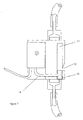
- the device shown in Figure 1 of the drawings includes a housing 10 in the form of a machined aluminium block with a vertical hole in which a sealed stainless steel flow tube 2 is mounted.
- a sealed housing or slug 5 Within the flow tube 2 there is a sealed housing or slug 5 and there is a round magnet 4 fixed inside the housing or slug 5.
- the slug 5 containing the magnet 4 is free to move up and down within the flow tube 2 but is restricted in its upward travel by a compression spring 3.
- the flow tube 2 is connected at both ends to flexible tubes 1 and 6.
- Flexible tube 6 is the inlet tube and flexible tube 1 is the outlet tube.
- the slug 5 containing the magnet 4 is a relatively close fit in the flow tube 2 and the cross-sectional dimensions of the slug 5 relative to those of the vertically extending flow tube 2 are so chosen that, for a given rate of flow of the liquid upwardly through the flow tube 2, a predetermined upward force is applied to the slug 5.
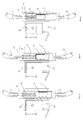
- a micro pneumatic switch 8 is mounted in the housing 10 by means of a fixing screw 9 and is responsive to the presence or absence of a magnetic field. It is so positioned that it is operated when the slug 5 containing the magnet 4 moves from the position shown in Figure 4 into the position shown in Figure 3 as a result of a reduction in the rate of liquid flow from inlet tube 6 to outlet tube 1.
- Line A is the point which the top of the slug 5 containing the magnet 4 needs to reach for the switch 8 to be in its "OFF" or non-alarm condition. If the rate of liquid flow diminishes to a point such that the top of the slug 5 falls below line A, then switch 8 will be in its "ON" position so as to cause the generation of an alarm signal.
- FIG. 2 A second cross-sectional view of the device is shown in Figure 2 .
- the switch 8 When the switch 8 is in the ON position, that is to say when the rate of flow of the liquid through the device is insufficient to maintain the top of the slug 5 at or above the level of line A, then the micro switch 8 provides an output air signal through a tube 14. This air flow is directed to a restrictor 13 and emits into a whistle chamber 11 so as to cause the emission of a whistle sound from the orifice 12.
- the whistle assembly comprising the restrictor 13, the chamber 11 and the orifice 11 are built into the device housing 10 so as to form an integral part of the device.
- Figures 3 and 4 of the drawings show the relative positions of the parts of the device when it is being used for extremely low flow rate alarm conditions, for example, below circa 10 cc/min. The device is thus in its most sensitive condition.
- the alarm is effectively primed waiting for the liquid flow to commence and is, therefore, providing a signal causing the whistle to sound.
- the space within the housing 10 permits the provision of an air whistle 12 that is connected internally to the output of the switch 8 and thus provides a built-in audible alarm.
- the air supply to the switch 8 is connected to the associated machine's air supply so that the switch 8 becomes live as soon as the machine is switched on.
- the output of the switch 8 has sufficient volume and pressure to operate a pressure switch or other device in addition to the built-in whistle to provide an additional low flow or no flow warning signal.
- This additional signal may readily be integrated into standard meter mix spray or injection or dispense machines to provide for an automatic machine stop should the operator not take the remedial required action if the alarm sounds.
- a delay can be introduced into the output signal of the automatic machine stop features such that any minimal spurious and intermittent alarm signals lasting under a second do not stop the machine. Thus, only an alarm condition of a few seconds duration will automatically stop the machine.
- the device is so designed as to minimise the likelihood of damage as a result of liquid spills or dust and all parts that might be exposed to fumes are chemically resistant and pose no potential spark or other explosion risks.
Landscapes
- Physics & Mathematics (AREA)
- General Physics & Mathematics (AREA)
- Fluid Mechanics (AREA)
- Indicating Or Recording The Presence, Absence, Or Direction Of Movement (AREA)
- Measuring Volume Flow (AREA)
Applications Claiming Priority (1)
| Application Number | Priority Date | Filing Date | Title |
|---|---|---|---|
| GBGB0808138.2A GB0808138D0 (en) | 2008-05-03 | 2008-05-03 | Liquid flow sensing systems |
Publications (1)
| Publication Number | Publication Date |
|---|---|
| EP2113751A1 true EP2113751A1 (de) | 2009-11-04 |
Family
ID=39537281
Family Applications (1)
| Application Number | Title | Priority Date | Filing Date |
|---|---|---|---|
| EP09251249A Withdrawn EP2113751A1 (de) | 2008-05-03 | 2009-05-01 | Flüssigkeitsströmungswächter |
Country Status (3)
| Country | Link |
|---|---|
| US (1) | US7938018B2 (de) |
| EP (1) | EP2113751A1 (de) |
| GB (1) | GB0808138D0 (de) |
Families Citing this family (4)
| Publication number | Priority date | Publication date | Assignee | Title |
|---|---|---|---|---|
| US20110196888A1 (en) * | 2010-02-10 | 2011-08-11 | Apple Inc. | Correlating Digital Media with Complementary Content |
| US8590562B2 (en) | 2010-12-17 | 2013-11-26 | Lincoln Industries Corporation | Fluid flow detection device |
| US9313389B2 (en) * | 2013-11-08 | 2016-04-12 | Htc Corporation | Camera assembly and electronic device |
| CN106197577B (zh) * | 2016-06-30 | 2019-01-04 | 太原理工大学 | 基于mems技术的无线无源流量传感器 |
Citations (7)
| Publication number | Priority date | Publication date | Assignee | Title |
|---|---|---|---|---|
| DE1943018A1 (de) * | 1968-09-13 | 1970-04-09 | Siemens Ag | Vorrichtung zur UEberwachung der Stroemung von durch Leitungen gefuehrten Medien |
| DE1906029A1 (de) * | 1969-02-07 | 1970-08-13 | Zeiss Carl Fa | Einrichtung zum UEberwachen der Stroemung einer Fluessigkeit |
| DE2443610A1 (de) * | 1974-09-12 | 1976-03-25 | Honsberg & Co Kg | Stroemungswaechter fuer fluessige und gasfoermige medien |
| GB2151383A (en) * | 1983-12-17 | 1985-07-17 | Stephan Paul Michlig | Flow detection device |
| DE8804848U1 (de) | 1987-11-30 | 1988-06-23 | Dr. Siebert & Kühn GmbH & Co. KG, 3504 Kaufungen | Vorrichtung zur Überwachung der Strömung flüssiger oder gasförmiger Medien |
| FR2718234A1 (fr) | 1994-03-29 | 1995-10-06 | Fafnir Airindex | Détecteur d'écoulement d'un fluide. |
| DE19620699C1 (de) * | 1996-05-23 | 1997-11-20 | Hanno Dipl Ing Schmitz | Strömungswächter mit Warnvorrichtung |
-
2008
- 2008-05-03 GB GBGB0808138.2A patent/GB0808138D0/en not_active Ceased
-
2009
- 2009-04-23 US US12/386,798 patent/US7938018B2/en not_active Expired - Fee Related
- 2009-05-01 EP EP09251249A patent/EP2113751A1/de not_active Withdrawn
Patent Citations (7)
| Publication number | Priority date | Publication date | Assignee | Title |
|---|---|---|---|---|
| DE1943018A1 (de) * | 1968-09-13 | 1970-04-09 | Siemens Ag | Vorrichtung zur UEberwachung der Stroemung von durch Leitungen gefuehrten Medien |
| DE1906029A1 (de) * | 1969-02-07 | 1970-08-13 | Zeiss Carl Fa | Einrichtung zum UEberwachen der Stroemung einer Fluessigkeit |
| DE2443610A1 (de) * | 1974-09-12 | 1976-03-25 | Honsberg & Co Kg | Stroemungswaechter fuer fluessige und gasfoermige medien |
| GB2151383A (en) * | 1983-12-17 | 1985-07-17 | Stephan Paul Michlig | Flow detection device |
| DE8804848U1 (de) | 1987-11-30 | 1988-06-23 | Dr. Siebert & Kühn GmbH & Co. KG, 3504 Kaufungen | Vorrichtung zur Überwachung der Strömung flüssiger oder gasförmiger Medien |
| FR2718234A1 (fr) | 1994-03-29 | 1995-10-06 | Fafnir Airindex | Détecteur d'écoulement d'un fluide. |
| DE19620699C1 (de) * | 1996-05-23 | 1997-11-20 | Hanno Dipl Ing Schmitz | Strömungswächter mit Warnvorrichtung |
Also Published As
| Publication number | Publication date |
|---|---|
| GB0808138D0 (en) | 2008-06-11 |
| US7938018B2 (en) | 2011-05-10 |
| US20100024566A1 (en) | 2010-02-04 |
Similar Documents
| Publication | Publication Date | Title |
|---|---|---|
| CA1329896C (en) | Empty container detector | |
| US5014543A (en) | Leak detector | |
| US7938018B2 (en) | Liquid flow sensing systems | |
| JP6150862B2 (ja) | 液体計量ポンプ、およびそのようなポンプのための圧力の変動を検出するための装置 | |
| KR920700716A (ko) | 액체 공급 시스템에서 공기를 검출하기 위한 장치 및 방법 | |
| CA2543955A1 (en) | Syringe pump rapid occlusion detection system | |
| WO2005000731A3 (en) | Diaphram metering chamber dispensing systems | |
| US20180306682A1 (en) | Smart pump for a portable gas detection instrument | |
| CN114788909A (zh) | 用于输液泵的输液状态检测方法及输液泵 | |
| CN116871078A (zh) | 用于排出液体、尤其是排出药用液体的分配器以及包括这种分配器的套件 | |
| EP2133669A1 (de) | Stufensensorsysteme | |
| CN114026330B (zh) | 流体泵 | |
| WO1992019531A1 (en) | Air/vapour separation device | |
| CN1906467B (zh) | 流体产品分配装置 | |
| US8146625B2 (en) | Fail-safe method and apparatus for aspirating and/or dispensing liquids in automated laboratory instruments | |
| US8289175B2 (en) | Fluid level warning system for vehicle | |
| US6943690B2 (en) | Flow verification mechanism | |
| JP2002151458A (ja) | 流体定量供給装置 | |
| EP2050711B1 (de) | Vorrichtung zur Detektion von Dampfrückgewinnung | |
| GB2259497A (en) | A fuel dispenser. | |
| EP3420429B1 (de) | Vorrichtung zur bereitstellung einer flüssigkeit aus einem vorratsbehälter zu einer flüssigkeitseinlassvorrichtung | |
| JP3343042B2 (ja) | 流量検出器及びそれを用いたポンプ | |
| EP1898186B1 (de) | Verfahren und Vorrichtung zur Detektierung des Gasblasengehalts einer Flüssigkeitsströmung | |
| EP1995209A1 (de) | Dampfrückgewinnungsystem, Verfahren zu dessen Steuerung und Kraftstoffabgabevorrichtung | |
| EP1739053B1 (de) | Gasrückführungssystem für Kraftstoff mit Temperatur-Sensor und Verfahren |
Legal Events
| Date | Code | Title | Description |
|---|---|---|---|
| PUAI | Public reference made under article 153(3) epc to a published international application that has entered the european phase |
Free format text: ORIGINAL CODE: 0009012 |
|
| AK | Designated contracting states |
Kind code of ref document: A1 Designated state(s): AT BE BG CH CY CZ DE DK EE ES FI FR GB GR HR HU IE IS IT LI LT LU LV MC MK MT NL NO PL PT RO SE SI SK TR |
|
| 17P | Request for examination filed |
Effective date: 20100604 |
|
| 17Q | First examination report despatched |
Effective date: 20110117 |
|
| GRAP | Despatch of communication of intention to grant a patent |
Free format text: ORIGINAL CODE: EPIDOSNIGR1 |
|
| RIC1 | Information provided on ipc code assigned before grant |
Ipc: G01F 1/28 20060101AFI20120521BHEP Ipc: G01P 13/00 20060101ALI20120521BHEP |
|
| STAA | Information on the status of an ep patent application or granted ep patent |
Free format text: STATUS: THE APPLICATION IS DEEMED TO BE WITHDRAWN |
|
| 18D | Application deemed to be withdrawn |
Effective date: 20121019 |