EP2113716A1 - A light fitting to be recessed into a suspended power distribution track - Google Patents
A light fitting to be recessed into a suspended power distribution track Download PDFInfo
- Publication number
- EP2113716A1 EP2113716A1 EP08425295A EP08425295A EP2113716A1 EP 2113716 A1 EP2113716 A1 EP 2113716A1 EP 08425295 A EP08425295 A EP 08425295A EP 08425295 A EP08425295 A EP 08425295A EP 2113716 A1 EP2113716 A1 EP 2113716A1
- Authority
- EP
- European Patent Office
- Prior art keywords
- light fitting
- platform
- contact
- track
- devices
- Prior art date
- Legal status (The legal status is an assumption and is not a legal conclusion. Google has not performed a legal analysis and makes no representation as to the accuracy of the status listed.)
- Granted
Links
Images


Classifications
-
- H—ELECTRICITY
- H01—ELECTRIC ELEMENTS
- H01R—ELECTRICALLY-CONDUCTIVE CONNECTIONS; STRUCTURAL ASSOCIATIONS OF A PLURALITY OF MUTUALLY-INSULATED ELECTRICAL CONNECTING ELEMENTS; COUPLING DEVICES; CURRENT COLLECTORS
- H01R25/00—Coupling parts adapted for simultaneous co-operation with two or more identical counterparts, e.g. for distributing energy to two or more circuits
- H01R25/14—Rails or bus-bars constructed so that the counterparts can be connected thereto at any point along their length
- H01R25/142—Their counterparts
-
- F—MECHANICAL ENGINEERING; LIGHTING; HEATING; WEAPONS; BLASTING
- F21—LIGHTING
- F21V—FUNCTIONAL FEATURES OR DETAILS OF LIGHTING DEVICES OR SYSTEMS THEREOF; STRUCTURAL COMBINATIONS OF LIGHTING DEVICES WITH OTHER ARTICLES, NOT OTHERWISE PROVIDED FOR
- F21V17/00—Fastening of component parts of lighting devices, e.g. shades, globes, refractors, reflectors, filters, screens, grids or protective cages
- F21V17/10—Fastening of component parts of lighting devices, e.g. shades, globes, refractors, reflectors, filters, screens, grids or protective cages characterised by specific fastening means or way of fastening
- F21V17/18—Latch-type fastening, e.g. with rotary action
-
- F—MECHANICAL ENGINEERING; LIGHTING; HEATING; WEAPONS; BLASTING
- F21—LIGHTING
- F21V—FUNCTIONAL FEATURES OR DETAILS OF LIGHTING DEVICES OR SYSTEMS THEREOF; STRUCTURAL COMBINATIONS OF LIGHTING DEVICES WITH OTHER ARTICLES, NOT OTHERWISE PROVIDED FOR
- F21V21/00—Supporting, suspending, or attaching arrangements for lighting devices; Hand grips
- F21V21/34—Supporting elements displaceable along a guiding element
- F21V21/35—Supporting elements displaceable along a guiding element with direct electrical contact between the supporting element and electric conductors running along the guiding element
-
- F—MECHANICAL ENGINEERING; LIGHTING; HEATING; WEAPONS; BLASTING
- F21—LIGHTING
- F21S—NON-PORTABLE LIGHTING DEVICES; SYSTEMS THEREOF; VEHICLE LIGHTING DEVICES SPECIALLY ADAPTED FOR VEHICLE EXTERIORS
- F21S8/00—Lighting devices intended for fixed installation
- F21S8/02—Lighting devices intended for fixed installation of recess-mounted type, e.g. downlighters
-
- F—MECHANICAL ENGINEERING; LIGHTING; HEATING; WEAPONS; BLASTING
- F21—LIGHTING
- F21V—FUNCTIONAL FEATURES OR DETAILS OF LIGHTING DEVICES OR SYSTEMS THEREOF; STRUCTURAL COMBINATIONS OF LIGHTING DEVICES WITH OTHER ARTICLES, NOT OTHERWISE PROVIDED FOR
- F21V23/00—Arrangement of electric circuit elements in or on lighting devices
- F21V23/02—Arrangement of electric circuit elements in or on lighting devices the elements being transformers, impedances or power supply units, e.g. a transformer with a rectifier
- F21V23/026—Fastening of transformers or ballasts
-
- F—MECHANICAL ENGINEERING; LIGHTING; HEATING; WEAPONS; BLASTING
- F21—LIGHTING
- F21Y—INDEXING SCHEME ASSOCIATED WITH SUBCLASSES F21K, F21L, F21S and F21V, RELATING TO THE FORM OR THE KIND OF THE LIGHT SOURCES OR OF THE COLOUR OF THE LIGHT EMITTED
- F21Y2103/00—Elongate light sources, e.g. fluorescent tubes
Definitions
- the present invention relates to a light fitting to be recessed into a suspended power distribution track and specifically to a light fitting with a fluorescent lamp which can be fitted reversibly into a power distribution track.
- Branch plugs, light fittings, ventilators and the like can be connected to any point along the length of these channels, as required, using the channels as suspension elements.
- These tracks are essentially composed of a metal casing which forms a downwardly open channel in which bus bars are housed and in which electrical components can also be accommodated.
- two opposing parallel edges of the casing facing each other, serve as a support for the equipment to be connected to the channel.
- the rotation of the contact head provides both the electrical connection and the fastening to the track, using a kind of cam-like mechanical catch.
- the elements requiring relatively frequent replacement must be accessible without the need to remove the light fitting from the track.
- the installation must be carried out with the power turned off, the power being switched on only on completion of the installation.
- the track section 1 is essentially composed of a straight metal casing 2, made from bent sheet metal or extruded light alloy, forming a downwardly open channel, whose sides can house two identical straight supports 3, extruded from insulating plastics material.
- the casing 2 can house one support only, as shown in the drawing.
- a plurality of parallel straight recesses, opening on one side of the support, is formed in the support 3, which has rectangular cross section, one conducting element being housed in each recess.
- FIG. 1 there are six recesses, housing four T-section bus bars 4, 5, 6 and 7, which are coextruded with the support (the material of which incorporates the head of each bar), for distributing a three-phase current and voltage system and its neutral, together with two bus bars 8 and 9 of circular cross section, for distributing an auxiliary voltage or possibly electrical signals.
- Electrical signals can also be distributed by a bus composed of a twisted pair 13 which is housed in a recess 14 formed in the upper part of the casing 2 and which can be removed therefrom to form a local branch, using insulation piercing connectors, an example of a preferred embodiment of which is described in Italian patent application MI2007A000017 filed on 8 January 2007 .
- the butt joining of two track sections is generally done by using connectors composed of a sleeve 10 of insulating material, housing electrical contact blades and receptacles, collectively identified by the reference numeral 11, the number and configuration of which are appropriate for connection to the bus bars 4-9 of the support 3.
- Half of the length of the sleeve 10 is fitted on to the end of the support 3, as indicated by the arrow 12.
- the other half of the sleeve is fitted on to the end of another support, identical to the support 3 and belonging to a track section whose end is juxtaposed to the first.
- the other half of the sleeve can be inserted into an L, T, X or flexible joint for connection between track sections, for example as detailed in European patent application No. 07425068.2, filed on 6 February 2007 .
- Figure 1 shows a second electrical connection sleeve 15, identical to the sleeve 10, inserted into the opposite end of the track section 1.
- Figures 2 and 3 show schematically, in perspective from two opposite viewpoints, the structure of the light fitting proposed by the present invention.
- the fitting is composed of an elongate platform 18 of sheet metal, conveniently bent and cut to form two lateral stiffening ribs 19 and 20 and a reflector 21, positioned centrally with respect to the length, this reflector housing two fitting sockets, of which one, 22, is shown, and a fluorescent tube 23 which is fitted into the sockets.
- a conventional reactor or ballast 24 for fluorescent lamps is fixed on top of the reflector 21 by means of screws.
- the reactor can be replaced by an electronic controller in accordance with the latest technology.
- fastening devices 25 and 26 Adjacent to the reflector ends two fastening devices 25 and 26 are mounted on the platform 18, these devices being operable manually, without the aid of tools, for fastening the fitting to the track.
- the placing of the fastening devices very close to the ends of the reflector is essential for ergonomic reasons: the standard length of commercially available fluorescent tubes is 1149 mm (120 cm nominal).
- the distance between them must not exceed 1200-1300 mm.
- Housings are formed in the contact head for a plurality of electrical contact devices.
- the contact devices can be positioned in the housings on one or other side of the contact head, the position being chosen according to the required orientation of the installation of the light fitting in the track.
- Figure 2 shows two of these contact devices 28 and 29, positioned in the contact head so as to come into contact with the bus bars 5 and 7 of the support 3 ( Fig. 1 ) when the light fitting is recessed into the track in the orientation shown in Figure 2 .
- any portion of the platform 18, except the portion in which the connector 27 is located, can be positioned without mechanical interference at the end of the track section 1 in which the sleeve 10 is present.
- Figure 3 shows the two contact devices positioned on the opposite side of the contact head, again in order to contact the bus bars 5 and 7 of the support 3 ( Fig. 1 ) when the light fitting is recessed into the track in the orientation shown in Figure 3 , in other words after rotation through 180° with respect to the orientation shown in Figure 2 .
- This rotation can be carried out in order to avoid any interference of the connector 27 with one or other of the sleeves 10 and 15 ( Fig. 1 ).
- an aperture 30 is formed in the end of the platform 18, opposite the end on which the connector 27 is located, and a socket 32 is mounted on the platform at the position of this aperture (the platform being conveniently bent to form a support tab 31) for the insertion of an ordinary starter device 33 of the fluorescent tube.
- the starter is housed within the aperture 30, through which it can be accessed for removal and replacement when necessary.
- a rephasing capacitor 35 can also be mounted on the reflector, where it is retained by a fork 34.
- the reactor and starter can be replaced with an electronic power supply device, mounted in the fitting, to improve efficiency.
- the electronic device can be complemented by a local electronic programming device which switches the light fitting on and off automatically.
- the programming module can be replaced by a module controlled by signals received through the auxiliary bars 8 and 9 ( Fig. 1 ).
- control signals can be received through the twisted pair 13 ( Fig. 1 ) to which connection is made by means of an insulation piercing connector, which is provided with two lengths of cable terminating in contact pins for tool-free insertion into a socket of the control module.
- the light fitting installation sequence is as follows:
- the platform 18 is made from a metal sheet which is conveniently bent to form the two lateral stiffening ribs 19 and 20.
- the sheet is cut (or punched) and bent to form two opposing wings 36 and 37 extending in the median part of the platform and bent upwards, these wings forming the sides of the reflector in which the fluorescent tube is housed.
- the reflector is closed at its top and ends by a cover 38 made from cut and bent sheet metal, with two sides 39 and 40 which are superimposed on the wings 36 and 37 and which are fixed to these by electric spot welding.
- Convenient apertures are cut in the cover 38, to enable the reactor (or equivalent electronic power supply device) and the sockets for connection to the fluorescent tube to be fixed with self-tapping screws, and to provide access to the terminal blocks of these sockets (apertures 41, 42).
- Tabs 43 and 44 for supporting and positioning wiring, can also be formed by cutting in the sides 39 and 40 of the cover.
- Convenient apertures 48, 49, 55 are also formed for accessing and operating the fastening devices 25 and 26 ( Fig. 2 ) and the contact head of the connector 27.
- an aperture 30 is formed at the end of the platform 18 opposite the end at which the connector 27 is located, for access to the starter 33 or to a programmable control device fitted in place of the starter.
- the aperture 30 can be covered by an openable hatch which is not shown.
- the platform is bent upwards to form a tab 31, provided with holes for fixing, by means of screws, a conventional socket 32 for fitting the starter 33.
- Two plugs 51 and 52 made from plastics material, provided with two fixing pins which are force-fitted into the ribs 19 and 20, are used to cover the ends of the platform, purely in order to improve the appearance.
- Figure 5 shows a cross section, taken through I-I in Figure 2 , of the light fitting when installed and recessed into the track 1.
- the lateral ribs 19 and 20 bear on the lower parts of the flanges 16 and 17 of the casing 2 of the track, each of these flanges being conveniently provided with a recess for the positioning and partial housing of the ribs.
- the platform 18 is fixed to the casing 2 by the fastening devices 25 and 26 ( Fig. 2 ), each of which is provided with a pair of teeth 53 and 54 which are superimposed on the flanges 16 and 17 of the casing.
- the reflector 21 is housed inside the casing, together with the fluorescent tube 23 and the reactor 24 and the rephasing capacitor if present, which are mounted on top of the cover of the casing.
- the underside of the reflector is closed, and the whole platform 18 is protected, by a translucent shield 56 made from plastics material.
- the shield is provided with flanges 57 and 58 which are snap-fitted on to the ribs 19 and 20 of the platform 18.
- the shield can easily be removed for the purpose of replacing the fluorescent tube and the starter, and, if the light fitting is provided with a programmable device of a known type for switching it on and off, for the purpose of accessing and programming this device.
- Figure 5 also shows part of the contact head of the connector 27 in which a pair of contact devices 28 and 29 are housed.
- a third contact device (not shown) makes the electrical connection with an earth contact element 82 which comes into contact with the track casing 2.
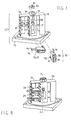
- Figure 6 is an exploded perspective view of a preferred embodiment of the fastening devices 25 and 26, used in the light fitting.
- the fastening device comprises a rectangular parallelepipedal box 60, preferably made by moulding from plastics material, which houses two fastening sliding members 158 and 59 which are formed by cutting from a metal sheet and bent in a double L configuration in cross section, and which are slidable transversely.
- the opposite ends 53 and 54 of the sliding members having a width L1 which is less than the width L of the sliding members, form a pair of fastening teeth which emerge laterally from the box 60, which is provided for this purpose with two openings 61 and 62 on its opposite sides 63 and 64.
- the projection of the teeth 53 and 54 from the sides 63 and 64 is determined by the interference of the sliding members 158 and 59 with the sides of the box.
- a tab 65, 66 is formed by cutting and bending on the vertical wall of each of the sliding members, and acts as a locating head for a helical compression spring 67 interposed between the two sliding members.
- the spring tends to move the sliding members away from each other, in such a way that the teeth 53 and 54 project from the sides of the box.
- the bottom wall of the box 60 has two apertures 68 and 69, through which it is possible to insert two fingers (namely the index finger and the thumb, allowing a forceful grip) and exert a compressive force on the vertical walls to bring the two sliding members together and retract the two teeth 53 and 54.
- the box complete with the sliding members and the spring, is covered with a lid 71 made from sheet metal bent into a C shape.
- Both the lid and the box 1 are provided with a pair of apertures for the passage of the screws 45 ( Fig. 4 ) which fix the device to the platform 18.
- the screws preferably engage with the lid 71, whose apertures are conveniently provided with threaded bushes.
- An upwardly extending fin of plastics material 72, 73 is snap-fitted on to each of the sliding members 158, 59.
- the fins 72 and 73 are provided with fastening teeth 74 and 75 and with register pins which engage in corresponding apertures of the sliding members 158 and 59 and ensure that the fins are correctly and stably positioned on the corresponding sliding members.
- the pair of fins 72, 73 forms a kind of wedge which acts as a guide for the insertion of the fastening device into the channel of the track casing, and for the snap-fitting of the fastening teeth to the edges 16 and 17 of the casing 2 ( Fig. 5 ).
- the connector 27 is composed of a square base plate 76, fixed by screws 47 ( Fig. 4 ) to the platform 18, on which plate is mounted a contact head which can rotate through a certain angle with an axis of rotation A-A perpendicular to the base plate.
- the angle of rotation which is in the range from 45° to 90° (and is preferably equal to 60°), is limited, in a known way, by stops (not shown) which define an insertion position (shown in Figures 7 and 8 ), in which the contact head can be inserted into the channel, and an electrical contact position, in which the contact blades penetrate into the recesses of the support 3 and make the electrical contact with the bus bars housed there.
- the head can be rotated, in a known way, by moving the head with a screwdriver which is inserted into a housing formed in the lower part of the head and accessible from the lower face of the base plate.
- the head can be provided with a graspable projection, accessible from the underside of the base plate, for the manual operation of the head without the need for tools.
- the head is composed of a central body or core 77 extending towards the axis of rotation A-A, from which core there radially extend two wings 78 and 79 which are positioned symmetrically about the axis of rotation and which, according to an innovative feature, are identical to each other and are axially symmetrical about the axis A-A.
- An identical plurality of housings is formed in the two wings 78 and 79, the number of housings being equal to the number of the bus bars in the support 3 and having the same spacing in order to house a corresponding plurality of electrical connection devices.
- one of these housings is identified by the reference numeral 80.
- Figure 8 shows, by way of example (as shown previously in Figure 2 ), how two connection devices 28 and 29 are removably housed in the flange 79 and are positioned so as to make the electrical contact with the bus bars 5 and 7 of the support 3 ( Fig. 1 ).
- connection devices 28 and 29 In order to make the connection to the same bus bars when the light fitting (and therefore the connector 27) is to be positioned in the track in an orientation rotated through 180° with respect to the orientation shown in Figure 8 (and therefore in the orientation shown in Figure 7 ), it is simply necessary to position the connection devices 28 and 29 in the corresponding housings formed in the flange 78.
- the central body 77 of the rotating contact head extends upwards into a support 81, on which is fitted a metal clip 82, conveniently shaped to form a cylindrical earth contact surface and, positioned inside this surface, a contact clamp 83 into which is inserted the blade 84 of an electrical connection device 85.
- the metal clip 82 comes into contact with the metal casing 2 of the track, which acts as an earth conductor.
- the electrical earth contact is provided for any angular position of the contact head other than its insertion position, and precedes the electrical connection to the bus bars.
- the disconnection of the earth contact follows the disconnection from the bus bars when the contact head is rotated from the contact position and placed in the insertion position.
- the electrical connection device or earth contact device 85 is essentially composed of a box of insulating material 87, with a front face closed by a lever 88 pivoted on the box and provided with an aperture 89 for the introduction of an electrical cable end.
- a contact spring (not shown) is housed in the box and is released by the lever 88.
- the contact spring securely clamps the cable end, which has been inserted into the aperture 89, against an inner portion of the contact blade 84, the outer portion of which emerges from a lateral face of the box.
- the electrical connection can easily be made without the use of tools, by exerting pressure manually on the end portion of the lever.
- the operation can also be carried out with the box already snap-fitted removably into a housing 90 formed in the central body 77 of the rotating head, the housing being provided with a groove 91 for the passage of the contact blade 84 and its insertion into the receptacle 83.
- the box 87 is fixed in its housing 90 by a resilient tab, terminating in a fastening tooth 92, formed on the side of the box opposite that from which the contact blade 84 emerges.
- the structure of the electrical connection devices for making the electrical contact with the auxiliary bus bars 8 and 9 is identical ( Fig. 1 ).
- the devices for electrical connection to the bus bars are very similar to those described above, the only difference being that a pair of juxtaposed parallel blades 93 and 94 emerges from the box to form a resilient contact clamp in which one of the bars 4, 5, 6 and 7 of Figure 1 is clamped.
- the light fitting can be prepared for installation, in one or other of the two opposite orientations required to avoid interference of the connector with the sleeves 11 and 15 ( Fig. 1 ), simply by connecting the light fitting power supply cable ends to the contact devices 28 and 29 (if this has not already been done in the factory) and inserting these devices into the appropriate housings, such as the housing 80, of one or other flange 78, 79 of the contact head.
Landscapes
- Engineering & Computer Science (AREA)
- General Engineering & Computer Science (AREA)
- Arrangement Of Elements, Cooling, Sealing, Or The Like Of Lighting Devices (AREA)
- Details Of Connecting Devices For Male And Female Coupling (AREA)
- Connector Housings Or Holding Contact Members (AREA)
- Non-Portable Lighting Devices Or Systems Thereof (AREA)
Abstract
Description
- The present invention relates to a light fitting to be recessed into a suspended power distribution track and specifically to a light fitting with a fluorescent lamp which can be fitted reversibly into a power distribution track.
- It is known that suspended power distribution tracks are widely used for electricity distribution, for example in offices, shops and commercial centres.
- Branch plugs, light fittings, ventilators and the like can be connected to any point along the length of these channels, as required, using the channels as suspension elements.
- Examples of these tracks are provided in European patent
EP 0015356 , German patent applicationDE 10241941 , and, more recently, European patent application No.06425836.1 filed on 14 December 2006 - These tracks are essentially composed of a metal casing which forms a downwardly open channel in which bus bars are housed and in which electrical components can also be accommodated.
- At the position of the lower opening, two opposing parallel edges of the casing, facing each other, serve as a support for the equipment to be connected to the channel.
- There are also known light fittings, particularly those using straight fluorescent lamps, which are fitted to the outside of these tracks, using an electrical contact head which is inserted into the track.
- The rotation of the contact head provides both the electrical connection and the fastening to the track, using a kind of cam-like mechanical catch.
- An example is provided by the cited document
DE 10241941 . - One limitation of these light fittings is that they are exposed and vulnerable to impact and damage, with a risk of breakage of the fluorescent tube.
- In many applications, in storehouses for example, it is therefore necessary to provide light fittings which are protected from impact, and, unless special armoured structures are used, it is desirable to use the tracks as elements which provide intrinsic protection for the light fittings.
- In order to do this, it is necessary to overcome a number of problems relating to the arrangement of the various components and the consequent necessity of allowing the fitting to be installed in two different orientations.
- The elements requiring relatively frequent replacement (such as the fluorescent tube and the starter, if present) must be accessible without the need to remove the light fitting from the track.
- Additionally, for reasons of safety and continuity of operation of the system, the installation must be carried out with the power turned off, the power being switched on only on completion of the installation.
- Furthermore, as installation takes place in an elevated location which is accessible only with a ladder or staging, it must be possible for the installation to be carried out easily, possibly without the use of any tools and in a purely manual way, by a single operator, without the risk of deforming or damaging sensitive elements such as the blades for contacting the bus bars of the track.
- All these requirements are met by a light fitting whose features are described in the appended claims.
- The features and advantages of the invention will be made clear by the following description of a preferred embodiment and of variants thereof, provided with reference to the appended drawings, in which:
-
Figure 1 is a perspective view of a power distribution track to which the light fitting of the present invention is to be connected; -
Figure 2 is an overall perspective view of the light fitting of the present invention; -
Figure 3 is a perspective view of the light fitting ofFigure 2 , viewed from the opposite direction to that ofFigure 2 ; -
Figure 4 is a more detailed exploded perspective view of the light fitting ofFigures 2 and 3 ; -
Figure 5 is a cross-sectional view, taken through the section I-I inFigure 2 , of the light fitting of the preceding figures, installed in the track ofFigure 1 ; -
Figure 6 is an exploded perspective view of a preferred embodiment of a device for fastening the light fitting of the preceding figures to the track; -
Figure 7 is an exploded perspective view of a preferred embodiment of an electrical connector for the light fitting of the preceding figures; -
Figure 8 is a perspective view of the light fitting ofFigure 7 , viewed from the opposite direction to that ofFigure 7 . - Elements which are functionally and structurally equivalent are identified by the same reference numerals in the different drawings.
- With reference to
Figure 1 , before examining the specific details of the light fitting, it will be appropriate to consider a preferred embodiment of the power distribution track section into which the light fitting is to be recessed. - The track section 1 is essentially composed of a
straight metal casing 2, made from bent sheet metal or extruded light alloy, forming a downwardly open channel, whose sides can house two identicalstraight supports 3, extruded from insulating plastics material. - Depending on the predominant requirements for use, the
casing 2 can house one support only, as shown in the drawing. - A plurality of parallel straight recesses, opening on one side of the support, is formed in the
support 3, which has rectangular cross section, one conducting element being housed in each recess. - In the preferred embodiment shown in
Figure 1 , there are six recesses, housing four T-section bus bars - Electrical signals can also be distributed by a bus composed of a
twisted pair 13 which is housed in arecess 14 formed in the upper part of thecasing 2 and which can be removed therefrom to form a local branch, using insulation piercing connectors, an example of a preferred embodiment of which is described in Italian patent applicationMI2007A000017 filed on 8 January 2007 - As shown schematically in
Figure 1 , the butt joining of two track sections is generally done by using connectors composed of asleeve 10 of insulating material, housing electrical contact blades and receptacles, collectively identified by thereference numeral 11, the number and configuration of which are appropriate for connection to the bus bars 4-9 of thesupport 3. - For further details of the structure of a preferred embodiment of these butt connectors (which are not essential for the purposes of the present invention), reference may be made to European patent application No.
07425067.1, filed on 6 February 2007 - Half of the length of the
sleeve 10 is fitted on to the end of thesupport 3, as indicated by thearrow 12. - The other half of the sleeve is fitted on to the end of another support, identical to the
support 3 and belonging to a track section whose end is juxtaposed to the first. - Alternatively, the other half of the sleeve can be inserted into an L, T, X or flexible joint for connection between track sections, for example as detailed in European patent application No.
07425068.2, filed on 6 February 2007 -
Figure 1 shows a secondelectrical connection sleeve 15, identical to thesleeve 10, inserted into the opposite end of the track section 1. - Clearly, it is impossible to make other electrical connections to the bus bars 4-9 in the areas occupied by the
sleeves - This fact must be borne in mind when considering the use of a light fitting which is to be positioned with part of its overall dimensions also occupying this space.
- This is essential in order to make the best use of the available space, and also in order to provide practically continuous light sources which can also be positioned in the area of the joints between track sections.
- To complete the description of the track section 1, it will be seen that the lower parts of the sides of the
casing 2 are bent towards each other, forming twoflanges support 3, and which also serve as fixing and supporting elements for the equipment which is connected to the track. -
Figures 2 and 3 show schematically, in perspective from two opposite viewpoints, the structure of the light fitting proposed by the present invention. - The fitting is composed of an
elongate platform 18 of sheet metal, conveniently bent and cut to form two lateralstiffening ribs reflector 21, positioned centrally with respect to the length, this reflector housing two fitting sockets, of which one, 22, is shown, and afluorescent tube 23 which is fitted into the sockets. - A conventional reactor or
ballast 24 for fluorescent lamps is fixed on top of thereflector 21 by means of screws. The reactor can be replaced by an electronic controller in accordance with the latest technology. - Adjacent to the reflector ends two
fastening devices platform 18, these devices being operable manually, without the aid of tools, for fastening the fitting to the track. - A preferred embodiment of these fastening devices is described in European patent application No.
08425053.9, filed on 31 January 2008 - The placing of the fastening devices very close to the ends of the reflector is essential for ergonomic reasons: the standard length of commercially available fluorescent tubes is 1149 mm (120 cm nominal).
- To enable both fastening devices to be operated simultaneously by a single operator, the distance between them must not exceed 1200-1300 mm.
- Otherwise, the operation becomes inconvenient or impossible and requires the action of two operators.
- A
connector 27 with a rotating electrical contact head, whose structure is symmetrical about its vertical axis of rotation, is fixed at one end of the platform. - Housings are formed in the contact head for a plurality of electrical contact devices.
- A preferred embodiment of these fastening devices is described in European patent application No.
08425054.7, filed on 31 January 2008 - The contact devices can be positioned in the housings on one or other side of the contact head, the position being chosen according to the required orientation of the installation of the light fitting in the track.
- This is permitted by the symmetrical structure of the contact head, and it is unnecessary to detach the
connector 27 from theplatform 18 and refit it in an orientation rotated through 180° with respect to the preceding orientation. - For example,
Figure 2 shows two of thesecontact devices bus bars 5 and 7 of the support 3 (Fig. 1 ) when the light fitting is recessed into the track in the orientation shown inFigure 2 . - In this case, any portion of the
platform 18, except the portion in which theconnector 27 is located, can be positioned without mechanical interference at the end of the track section 1 in which thesleeve 10 is present. -
Figure 3 , on the other hand, shows the two contact devices positioned on the opposite side of the contact head, again in order to contact thebus bars 5 and 7 of the support 3 (Fig. 1 ) when the light fitting is recessed into the track in the orientation shown inFigure 3 , in other words after rotation through 180° with respect to the orientation shown inFigure 2 . - This rotation can be carried out in order to avoid any interference of the
connector 27 with one or other of thesleeves 10 and 15 (Fig. 1 ). - To complete the description of the light fitting, it should be noted that an
aperture 30 is formed in the end of theplatform 18, opposite the end on which theconnector 27 is located, and asocket 32 is mounted on the platform at the position of this aperture (the platform being conveniently bent to form a support tab 31) for the insertion of anordinary starter device 33 of the fluorescent tube. - The starter is housed within the
aperture 30, through which it can be accessed for removal and replacement when necessary. - A rephasing
capacitor 35 can also be mounted on the reflector, where it is retained by afork 34. - The structure of the light fitting and some of its components is described more fully below.
- It should be noted at this point that, in the described configuration (lamp + reactor + starter + capacitor, if present, connected to each other and to the power source in a conventional way), only two
contact devices - However, the light fitting described above can be improved further without substantial modification.
- In the first place, it should be noted that the reactor and starter can be replaced with an electronic power supply device, mounted in the fitting, to improve efficiency.
- The electronic device can be complemented by a local electronic programming device which switches the light fitting on and off automatically.
- Alternatively, the programming module can be replaced by a module controlled by signals received through the auxiliary bars 8 and 9 (
Fig. 1 ). - Instead of being received from the auxiliary bars 8 and 9, the control signals can be received through the twisted pair 13 (
Fig. 1 ) to which connection is made by means of an insulation piercing connector, which is provided with two lengths of cable terminating in contact pins for tool-free insertion into a socket of the control module. - In this case, the light fitting installation sequence is as follows:
- the connection to the twisted pair is made with the insulation piercing connector;
- the control module is connected to the piercing connector;
- the light fitting is fastened to the track and the contact head is rotated.
- In the other cases, the only operations required are the fastening to the track and the rotation of the contact head.
- The structure of the various components of the light fitting will now be examined more closely.
- As shown in
Figure 4 , theplatform 18 is made from a metal sheet which is conveniently bent to form the twolateral stiffening ribs - The sheet is cut (or punched) and bent to form two opposing
wings 36 and 37 extending in the median part of the platform and bent upwards, these wings forming the sides of the reflector in which the fluorescent tube is housed. - The reflector is closed at its top and ends by a cover 38 made from cut and bent sheet metal, with two
sides 39 and 40 which are superimposed on thewings 36 and 37 and which are fixed to these by electric spot welding. - Convenient apertures are cut in the cover 38, to enable the reactor (or equivalent electronic power supply device) and the sockets for connection to the fluorescent tube to be fixed with self-tapping screws, and to provide access to the terminal blocks of these sockets (apertures 41, 42).
- Other apertures can be formed for the snap-fitting of a support and retaining
clamp 34 for a rephasing capacitor, if required. - Tabs 43 and 44, for supporting and positioning wiring, can also be formed by cutting in the
sides 39 and 40 of the cover. - Similarly, convenient apertures are cut in the
platform 18 to enable thefastening devices 25 and 26 (Fig. 2 ) and theconnector 27 to be fixed with screws (45, 46, 47). -
Convenient apertures fastening devices 25 and 26 (Fig. 2 ) and the contact head of theconnector 27. - Finally, an
aperture 30 is formed at the end of theplatform 18 opposite the end at which theconnector 27 is located, for access to thestarter 33 or to a programmable control device fitted in place of the starter. - Preferably, but not necessarily, the
aperture 30 can be covered by an openable hatch which is not shown. - At the position of the
aperture 30, the platform is bent upwards to form atab 31, provided with holes for fixing, by means of screws, aconventional socket 32 for fitting thestarter 33. - Two plugs 51 and 52 made from plastics material, provided with two fixing pins which are force-fitted into the
ribs -
Figure 5 shows a cross section, taken through I-I inFigure 2 , of the light fitting when installed and recessed into the track 1. - The
lateral ribs flanges casing 2 of the track, each of these flanges being conveniently provided with a recess for the positioning and partial housing of the ribs. - The
platform 18 is fixed to thecasing 2 by thefastening devices 25 and 26 (Fig. 2 ), each of which is provided with a pair ofteeth flanges - The
reflector 21 is housed inside the casing, together with thefluorescent tube 23 and thereactor 24 and the rephasing capacitor if present, which are mounted on top of the cover of the casing. - The underside of the reflector is closed, and the
whole platform 18 is protected, by atranslucent shield 56 made from plastics material. - The shield is provided with
flanges ribs platform 18. - The shield can easily be removed for the purpose of replacing the fluorescent tube and the starter, and, if the light fitting is provided with a programmable device of a known type for switching it on and off, for the purpose of accessing and programming this device.
-
Figure 5 also shows part of the contact head of theconnector 27 in which a pair ofcontact devices - A third contact device (not shown) makes the electrical connection with an
earth contact element 82 which comes into contact with thetrack casing 2. - These aspects are described more fully below.
-
Figure 6 is an exploded perspective view of a preferred embodiment of thefastening devices - The fastening device comprises a rectangular
parallelepipedal box 60, preferably made by moulding from plastics material, which houses twofastening sliding members - The opposite ends 53 and 54 of the sliding members, having a width L1 which is less than the width L of the sliding members, form a pair of fastening teeth which emerge laterally from the
box 60, which is provided for this purpose with twoopenings 61 and 62 on itsopposite sides - The projection of the
teeth sides members - A
tab helical compression spring 67 interposed between the two sliding members. - The spring tends to move the sliding members away from each other, in such a way that the
teeth - The bottom wall of the
box 60 has twoapertures teeth - The travel of the sliding members towards each other is limited by their interference with a
central rib 70 of the box. - The box, complete with the sliding members and the spring, is covered with a
lid 71 made from sheet metal bent into a C shape. - Both the lid and the box 1 are provided with a pair of apertures for the passage of the screws 45 (
Fig. 4 ) which fix the device to theplatform 18. - The screws preferably engage with the
lid 71, whose apertures are conveniently provided with threaded bushes. - An upwardly extending fin of
plastics material members - For this purpose, the
fins fastening teeth members - The pair of
fins edges Fig. 5 ). - The perspective drawings 7 and 8, taken from two opposing viewpoints, show further details of the structure of the
reversible connector 27. - The
connector 27 is composed of asquare base plate 76, fixed by screws 47 (Fig. 4 ) to theplatform 18, on which plate is mounted a contact head which can rotate through a certain angle with an axis of rotation A-A perpendicular to the base plate. - The angle of rotation, which is in the range from 45° to 90° (and is preferably equal to 60°), is limited, in a known way, by stops (not shown) which define an insertion position (shown in
Figures 7 and 8 ), in which the contact head can be inserted into the channel, and an electrical contact position, in which the contact blades penetrate into the recesses of thesupport 3 and make the electrical contact with the bus bars housed there. - The head can be rotated, in a known way, by moving the head with a screwdriver which is inserted into a housing formed in the lower part of the head and accessible from the lower face of the base plate.
- Alternatively, the head can be provided with a graspable projection, accessible from the underside of the base plate, for the manual operation of the head without the need for tools.
- The head is composed of a central body or
core 77 extending towards the axis of rotation A-A, from which core there radially extend twowings - An identical plurality of housings is formed in the two
wings support 3 and having the same spacing in order to house a corresponding plurality of electrical connection devices. InFigure 7 , one of these housings is identified by thereference numeral 80. -
Figure 8 shows, by way of example (as shown previously inFigure 2 ), how twoconnection devices flange 79 and are positioned so as to make the electrical contact with thebus bars 5 and 7 of the support 3 (Fig. 1 ). - In order to make the connection to the same bus bars when the light fitting (and therefore the connector 27) is to be positioned in the track in an orientation rotated through 180° with respect to the orientation shown in
Figure 8 (and therefore in the orientation shown inFigure 7 ), it is simply necessary to position theconnection devices flange 78. - As shown in
Figure 7 , thecentral body 77 of the rotating contact head extends upwards into asupport 81, on which is fitted ametal clip 82, conveniently shaped to form a cylindrical earth contact surface and, positioned inside this surface, acontact clamp 83 into which is inserted theblade 84 of anelectrical connection device 85. - When the contact head is inserted into the track and rotated, even by a small amount, relative to its insertion position, the
metal clip 82 comes into contact with themetal casing 2 of the track, which acts as an earth conductor. - It should therefore be noted that the electrical earth contact is provided for any angular position of the contact head other than its insertion position, and precedes the electrical connection to the bus bars.
- Similarly, the disconnection of the earth contact follows the disconnection from the bus bars when the contact head is rotated from the contact position and placed in the insertion position.
- As shown in the exploded view of
Figure 7 , the electrical connection device orearth contact device 85 is essentially composed of a box of insulatingmaterial 87, with a front face closed by alever 88 pivoted on the box and provided with anaperture 89 for the introduction of an electrical cable end. - A contact spring (not shown) is housed in the box and is released by the
lever 88. The contact spring securely clamps the cable end, which has been inserted into theaperture 89, against an inner portion of thecontact blade 84, the outer portion of which emerges from a lateral face of the box. - The electrical connection can easily be made without the use of tools, by exerting pressure manually on the end portion of the lever.
- The operation can also be carried out with the box already snap-fitted removably into a
housing 90 formed in thecentral body 77 of the rotating head, the housing being provided with agroove 91 for the passage of thecontact blade 84 and its insertion into thereceptacle 83. - The
box 87 is fixed in itshousing 90 by a resilient tab, terminating in a fastening tooth 92, formed on the side of the box opposite that from which thecontact blade 84 emerges. - The structure of the electrical connection devices for making the electrical contact with the auxiliary bus bars 8 and 9 is identical (
Fig. 1 ). - The devices for electrical connection to the bus bars, such as those identified by the
reference numerals parallel blades bars Figure 1 is clamped. - For further details of the structure of these contact devices, which are not relevant for the purposes of the present invention, reference may be made to European patent application No.
08425054.7, filed on 31 January 2008 - In conclusion, the light fitting can be prepared for installation, in one or other of the two opposite orientations required to avoid interference of the connector with the
sleeves 11 and 15 (Fig. 1 ), simply by connecting the light fitting power supply cable ends to thecontact devices 28 and 29 (if this has not already been done in the factory) and inserting these devices into the appropriate housings, such as thehousing 80, of one orother flange
Claims (6)
- A light fitting to be recessed into a suspended power distribution track (1), comprising:- an elongate platform (18) with a central portion forming a reflector (21) in which a straight fluorescent tube (23) is housed,- a pair of fastening devices (25, 26) mounted on said platform (18) adjacent to the ends of said reflector (21), and- an electrical connector (27) in the form of a rotating head for contacting bus bars (4-9) of said track (1), positioned at one end of said platform (18), said contact head having two identical wings positioned symmetrically with respect to the axis of rotation of said contact head, each of said wings having an identical plurality of housings (80) to removably house at least one pair (28, 29) of devices for making an electrical contact with said bus bars, in such a way that said light fitting can be recessed into said track equally well in either one of two opposing orientations which are rotated through 180° with respect to each other, said contact device (28, 29) being inserted into the housings of one or other of said wings (78, 79).
- A light fitting according to Claim 1, in which a reactor (24) or an equivalent electronic power supply device is mounted on the top (38) of said reflector.
- A light fitting according to Claim 1 or 2, in which a starter device (33) or an equivalent on/off switch device is mounted on said platform (18) at the end opposite the end on which said connector (27) is mounted.
- A light fitting according to any one of the preceding claims, in which said on/off switch device can be programmed through an aperture (30) of said platform (18).
- A light fitting according to any one of the preceding claims, in which said fastening devices (25, 26) can be operated independently of said contact head and comprise a pair of opposing sliding members (158, 59) whose opposing ends (53, 54) form a pair of fastening teeth, said sliding members (158, 59) being kept spaced apart by a compression spring (67) and being movable towards each other manually, using apertures (48, 49) of said platform, in order to carry out a fastening or detaching operation.
- A light fitting according to any one of the preceding claims, in which said electrical contact devices (28, 29) are snap-fitted into housings (80) in said wings (78, 79) of the contact head and each device is provided with a lever (88) enabling an electrical cable end to be inserted into said contact device and to be electrically connected to said contact device without the aid of tools.
Priority Applications (5)
| Application Number | Priority Date | Filing Date | Title |
|---|---|---|---|
| PT08425295T PT2113716E (en) | 2008-04-29 | 2008-04-29 | A light fitting to be recessed into a suspended power distribution track |
| ES08425295T ES2356705T3 (en) | 2008-04-29 | 2008-04-29 | LIGHTING ACCESSORY FOR YOUR SURVEY IN A SUSPENDED GUIDE FOR ELECTRICAL CURRENT DISTRIBUTION. |
| DE602008003896T DE602008003896D1 (en) | 2008-04-29 | 2008-04-29 | Recessed luminaire for installation in a suspended power distribution track |
| EP08425295A EP2113716B1 (en) | 2008-04-29 | 2008-04-29 | A light fitting to be recessed into a suspended power distribution track |
| AT08425295T ATE491115T1 (en) | 2008-04-29 | 2008-04-29 | RECESSED LUMINAIRE FOR INSTALLATION IN A SUSPENDED POWER DISTRIBUTION TRACK |
Applications Claiming Priority (1)
| Application Number | Priority Date | Filing Date | Title |
|---|---|---|---|
| EP08425295A EP2113716B1 (en) | 2008-04-29 | 2008-04-29 | A light fitting to be recessed into a suspended power distribution track |
Publications (2)
| Publication Number | Publication Date |
|---|---|
| EP2113716A1 true EP2113716A1 (en) | 2009-11-04 |
| EP2113716B1 EP2113716B1 (en) | 2010-12-08 |
Family
ID=39720689
Family Applications (1)
| Application Number | Title | Priority Date | Filing Date |
|---|---|---|---|
| EP08425295A Not-in-force EP2113716B1 (en) | 2008-04-29 | 2008-04-29 | A light fitting to be recessed into a suspended power distribution track |
Country Status (5)
| Country | Link |
|---|---|
| EP (1) | EP2113716B1 (en) |
| AT (1) | ATE491115T1 (en) |
| DE (1) | DE602008003896D1 (en) |
| ES (1) | ES2356705T3 (en) |
| PT (1) | PT2113716E (en) |
Cited By (5)
| Publication number | Priority date | Publication date | Assignee | Title |
|---|---|---|---|---|
| EP2631532A1 (en) * | 2012-02-24 | 2013-08-28 | Zumtobel Lighting GmbH | Strip lamp for mechanical and electrical connection to a support rail |
| EP2966347A4 (en) * | 2013-03-05 | 2016-11-30 | Linno Ltd | Bar-type lighting apparatus |
| EP3336420A1 (en) * | 2016-12-15 | 2018-06-20 | H4X e.U. | Lighting system |
| CN110726098A (en) * | 2019-10-14 | 2020-01-24 | 中山市叶子照明科技有限公司 | Lamp body connecting piece for track lamp and lamp |
| DE102022204266A1 (en) | 2022-04-29 | 2023-11-02 | H4X E.U. | Track profile for a profile light or for a track lighting system |
Citations (8)
| Publication number | Priority date | Publication date | Assignee | Title |
|---|---|---|---|---|
| EP0015356A1 (en) | 1978-10-13 | 1980-09-17 | F.LLI ZUCCHINI S.p.A. | Bipolar shunting device for multipolar electric lines of the armor-plated type |
| US6439749B1 (en) * | 2001-07-30 | 2002-08-27 | Jack V. Miller | Internal fixture tracklight system |
| DE10216390A1 (en) * | 2002-04-12 | 2003-10-30 | Helmut Matysik | Electric current supply rail for two-phase or three-phase current for lamps, has U-shaped cross-section with conductor strips embedded in insulating support on either side of U-section |
| DE10241941A1 (en) | 2002-09-10 | 2004-03-18 | Zumtobel Staff Gmbh | Lighting system connected to conductor rail, has an adaptor fixed to the light module and to docking elements to reliably set current pick-up head position |
| EP1473807A1 (en) * | 2003-04-30 | 2004-11-03 | Zumtobel Staff GmbH | Busbars system for illumination and locking device |
| EP1933434A1 (en) | 2006-12-14 | 2008-06-18 | BTICINO S.p.A. | Suspended electrical ducting and corresponding accessories |
| EP1956688A1 (en) | 2007-02-06 | 2008-08-13 | BTICINO S.p.A. | Concealed and preferably leaktight electrical butt joint for prefabricated lengths of electrical ducting, preassembled with one of the lengths. |
| EP1965477A1 (en) | 2007-02-06 | 2008-09-03 | BTICINO S.p.A. | Modular system for forming preassembled elbow, T, X or flexible connection joints for prefabricated sections of electrical ducting. |
-
2008
- 2008-04-29 ES ES08425295T patent/ES2356705T3/en active Active
- 2008-04-29 DE DE602008003896T patent/DE602008003896D1/en active Active
- 2008-04-29 EP EP08425295A patent/EP2113716B1/en not_active Not-in-force
- 2008-04-29 AT AT08425295T patent/ATE491115T1/en active
- 2008-04-29 PT PT08425295T patent/PT2113716E/en unknown
Patent Citations (8)
| Publication number | Priority date | Publication date | Assignee | Title |
|---|---|---|---|---|
| EP0015356A1 (en) | 1978-10-13 | 1980-09-17 | F.LLI ZUCCHINI S.p.A. | Bipolar shunting device for multipolar electric lines of the armor-plated type |
| US6439749B1 (en) * | 2001-07-30 | 2002-08-27 | Jack V. Miller | Internal fixture tracklight system |
| DE10216390A1 (en) * | 2002-04-12 | 2003-10-30 | Helmut Matysik | Electric current supply rail for two-phase or three-phase current for lamps, has U-shaped cross-section with conductor strips embedded in insulating support on either side of U-section |
| DE10241941A1 (en) | 2002-09-10 | 2004-03-18 | Zumtobel Staff Gmbh | Lighting system connected to conductor rail, has an adaptor fixed to the light module and to docking elements to reliably set current pick-up head position |
| EP1473807A1 (en) * | 2003-04-30 | 2004-11-03 | Zumtobel Staff GmbH | Busbars system for illumination and locking device |
| EP1933434A1 (en) | 2006-12-14 | 2008-06-18 | BTICINO S.p.A. | Suspended electrical ducting and corresponding accessories |
| EP1956688A1 (en) | 2007-02-06 | 2008-08-13 | BTICINO S.p.A. | Concealed and preferably leaktight electrical butt joint for prefabricated lengths of electrical ducting, preassembled with one of the lengths. |
| EP1965477A1 (en) | 2007-02-06 | 2008-09-03 | BTICINO S.p.A. | Modular system for forming preassembled elbow, T, X or flexible connection joints for prefabricated sections of electrical ducting. |
Cited By (9)
| Publication number | Priority date | Publication date | Assignee | Title |
|---|---|---|---|---|
| EP2631532A1 (en) * | 2012-02-24 | 2013-08-28 | Zumtobel Lighting GmbH | Strip lamp for mechanical and electrical connection to a support rail |
| EP2966347A4 (en) * | 2013-03-05 | 2016-11-30 | Linno Ltd | Bar-type lighting apparatus |
| US9958114B2 (en) | 2013-03-05 | 2018-05-01 | Linno, Ltd. | Linear lighting device |
| EP3336420A1 (en) * | 2016-12-15 | 2018-06-20 | H4X e.U. | Lighting system |
| AT519507A3 (en) * | 2016-12-15 | 2019-06-15 | H4X Eu | lighting system |
| US10323837B2 (en) | 2016-12-15 | 2019-06-18 | H4X E.U. | Lighting system |
| AT519507B1 (en) * | 2016-12-15 | 2020-11-15 | H4X Eu | Lighting system |
| CN110726098A (en) * | 2019-10-14 | 2020-01-24 | 中山市叶子照明科技有限公司 | Lamp body connecting piece for track lamp and lamp |
| DE102022204266A1 (en) | 2022-04-29 | 2023-11-02 | H4X E.U. | Track profile for a profile light or for a track lighting system |
Also Published As
| Publication number | Publication date |
|---|---|
| PT2113716E (en) | 2011-02-17 |
| ES2356705T3 (en) | 2011-04-12 |
| DE602008003896D1 (en) | 2011-01-20 |
| ATE491115T1 (en) | 2010-12-15 |
| EP2113716B1 (en) | 2010-12-08 |
Similar Documents
| Publication | Publication Date | Title |
|---|---|---|
| ES2699328T3 (en) | Contact protection system for power bars | |
| US5626488A (en) | Electrical terminal and coupling connector | |
| US6777611B2 (en) | Switch/power drop unit for modular wiring system | |
| EP2113716B1 (en) | A light fitting to be recessed into a suspended power distribution track | |
| JP2005522007A (en) | Low voltage distribution circuit | |
| US10581211B2 (en) | Busway stab assemblies and related systems and methods | |
| CA2286846A1 (en) | Lighting circuit, lighting system method and apparatus, socket assembly, lamp insulator assembly and components thereof | |
| US5008493A (en) | Holder with busbars for a busbar system | |
| EP3149809B1 (en) | Electrical connector for use with printed circuit boards | |
| US20240110692A1 (en) | Luminaire head with a removable cap | |
| EP1750338B1 (en) | A separator element for a mesh cable duct and a mesh cable duct comprising such element | |
| CA1199379A (en) | Skirting board structure for the distribution of electric energy and other similar services in civil use premises | |
| ES2286839T3 (en) | ELECTRICAL COUPLING SYSTEM. | |
| EP2678903B1 (en) | A modular electrical connection unit | |
| CA2243735A1 (en) | Connecting accessory for fluorescent lamps | |
| CN114207954A (en) | Adapter for electrically connecting a lighting device to an electrical track, lighting system comprising such an adapter and an electrical track | |
| GB2266810A (en) | Multi socket outlet assembly | |
| EP2113971B1 (en) | A connector for a suspended power distribution track | |
| FR2833771B1 (en) | ELECTRIC CHUTE WITH MEANS FOR RETAINING ELECTRICAL CABLES OR CONDUCTORS | |
| EP4270680A1 (en) | Busbar and trunking rail for luminaires or other electrical devices | |
| AU2019398165A1 (en) | Plug connector part for contacting in multiple spatial directions | |
| FI84952C (en) | Power withdrawal device for a wiring channel | |
| GB2266811A (en) | Switched socket outlet. | |
| EP3767766B1 (en) | Electric or electronic device | |
| EP0573254A1 (en) | Housing for control unit |
Legal Events
| Date | Code | Title | Description |
|---|---|---|---|
| PUAI | Public reference made under article 153(3) epc to a published international application that has entered the european phase |
Free format text: ORIGINAL CODE: 0009012 |
|
| AK | Designated contracting states |
Kind code of ref document: A1 Designated state(s): AT BE BG CH CY CZ DE DK EE ES FI FR GB GR HR HU IE IS IT LI LT LU LV MC MT NL NO PL PT RO SE SI SK TR |
|
| AX | Request for extension of the european patent |
Extension state: AL BA MK RS |
|
| 17P | Request for examination filed |
Effective date: 20100329 |
|
| GRAP | Despatch of communication of intention to grant a patent |
Free format text: ORIGINAL CODE: EPIDOSNIGR1 |
|
| AKX | Designation fees paid |
Designated state(s): AT BE BG CH CY CZ DE DK EE ES FI FR GB GR HR HU IE IS IT LI LT LU LV MC MT NL NO PL PT RO SE SI SK TR |
|
| GRAS | Grant fee paid |
Free format text: ORIGINAL CODE: EPIDOSNIGR3 |
|
| GRAA | (expected) grant |
Free format text: ORIGINAL CODE: 0009210 |
|
| AK | Designated contracting states |
Kind code of ref document: B1 Designated state(s): AT BE BG CH CY CZ DE DK EE ES FI FR GB GR HR HU IE IS IT LI LT LU LV MC MT NL NO PL PT RO SE SI SK TR |
|
| REG | Reference to a national code |
Ref country code: GB Ref legal event code: FG4D |
|
| REG | Reference to a national code |
Ref country code: CH Ref legal event code: EP |
|
| REG | Reference to a national code |
Ref country code: IE Ref legal event code: FG4D |
|
| REF | Corresponds to: |
Ref document number: 602008003896 Country of ref document: DE Date of ref document: 20110120 Kind code of ref document: P |
|
| REG | Reference to a national code |
Ref country code: PT Ref legal event code: SC4A Free format text: AVAILABILITY OF NATIONAL TRANSLATION Effective date: 20110210 |
|
| REG | Reference to a national code |
Ref country code: NL Ref legal event code: VDEP Effective date: 20101208 |
|
| REG | Reference to a national code |
Ref country code: ES Ref legal event code: FG2A Ref document number: 2356705 Country of ref document: ES Kind code of ref document: T3 Effective date: 20110412 |
|
| PG25 | Lapsed in a contracting state [announced via postgrant information from national office to epo] |
Ref country code: LT Free format text: LAPSE BECAUSE OF FAILURE TO SUBMIT A TRANSLATION OF THE DESCRIPTION OR TO PAY THE FEE WITHIN THE PRESCRIBED TIME-LIMIT Effective date: 20101208 Ref country code: NO Free format text: LAPSE BECAUSE OF FAILURE TO SUBMIT A TRANSLATION OF THE DESCRIPTION OR TO PAY THE FEE WITHIN THE PRESCRIBED TIME-LIMIT Effective date: 20110308 |
|
| LTIE | Lt: invalidation of european patent or patent extension |
Effective date: 20101208 |
|
| PG25 | Lapsed in a contracting state [announced via postgrant information from national office to epo] |
Ref country code: SI Free format text: LAPSE BECAUSE OF FAILURE TO SUBMIT A TRANSLATION OF THE DESCRIPTION OR TO PAY THE FEE WITHIN THE PRESCRIBED TIME-LIMIT Effective date: 20101208 Ref country code: NL Free format text: LAPSE BECAUSE OF FAILURE TO SUBMIT A TRANSLATION OF THE DESCRIPTION OR TO PAY THE FEE WITHIN THE PRESCRIBED TIME-LIMIT Effective date: 20101208 Ref country code: BG Free format text: LAPSE BECAUSE OF FAILURE TO SUBMIT A TRANSLATION OF THE DESCRIPTION OR TO PAY THE FEE WITHIN THE PRESCRIBED TIME-LIMIT Effective date: 20110308 Ref country code: FI Free format text: LAPSE BECAUSE OF FAILURE TO SUBMIT A TRANSLATION OF THE DESCRIPTION OR TO PAY THE FEE WITHIN THE PRESCRIBED TIME-LIMIT Effective date: 20101208 Ref country code: CY Free format text: LAPSE BECAUSE OF FAILURE TO SUBMIT A TRANSLATION OF THE DESCRIPTION OR TO PAY THE FEE WITHIN THE PRESCRIBED TIME-LIMIT Effective date: 20101208 Ref country code: LV Free format text: LAPSE BECAUSE OF FAILURE TO SUBMIT A TRANSLATION OF THE DESCRIPTION OR TO PAY THE FEE WITHIN THE PRESCRIBED TIME-LIMIT Effective date: 20101208 Ref country code: HR Free format text: LAPSE BECAUSE OF FAILURE TO SUBMIT A TRANSLATION OF THE DESCRIPTION OR TO PAY THE FEE WITHIN THE PRESCRIBED TIME-LIMIT Effective date: 20101208 Ref country code: SE Free format text: LAPSE BECAUSE OF FAILURE TO SUBMIT A TRANSLATION OF THE DESCRIPTION OR TO PAY THE FEE WITHIN THE PRESCRIBED TIME-LIMIT Effective date: 20101208 |
|
| PG25 | Lapsed in a contracting state [announced via postgrant information from national office to epo] |
Ref country code: GR Free format text: LAPSE BECAUSE OF FAILURE TO SUBMIT A TRANSLATION OF THE DESCRIPTION OR TO PAY THE FEE WITHIN THE PRESCRIBED TIME-LIMIT Effective date: 20110309 Ref country code: IS Free format text: LAPSE BECAUSE OF FAILURE TO SUBMIT A TRANSLATION OF THE DESCRIPTION OR TO PAY THE FEE WITHIN THE PRESCRIBED TIME-LIMIT Effective date: 20110408 Ref country code: CZ Free format text: LAPSE BECAUSE OF FAILURE TO SUBMIT A TRANSLATION OF THE DESCRIPTION OR TO PAY THE FEE WITHIN THE PRESCRIBED TIME-LIMIT Effective date: 20101208 Ref country code: EE Free format text: LAPSE BECAUSE OF FAILURE TO SUBMIT A TRANSLATION OF THE DESCRIPTION OR TO PAY THE FEE WITHIN THE PRESCRIBED TIME-LIMIT Effective date: 20101208 |
|
| PG25 | Lapsed in a contracting state [announced via postgrant information from national office to epo] |
Ref country code: RO Free format text: LAPSE BECAUSE OF FAILURE TO SUBMIT A TRANSLATION OF THE DESCRIPTION OR TO PAY THE FEE WITHIN THE PRESCRIBED TIME-LIMIT Effective date: 20101208 Ref country code: PL Free format text: LAPSE BECAUSE OF FAILURE TO SUBMIT A TRANSLATION OF THE DESCRIPTION OR TO PAY THE FEE WITHIN THE PRESCRIBED TIME-LIMIT Effective date: 20101208 Ref country code: SK Free format text: LAPSE BECAUSE OF FAILURE TO SUBMIT A TRANSLATION OF THE DESCRIPTION OR TO PAY THE FEE WITHIN THE PRESCRIBED TIME-LIMIT Effective date: 20101208 |
|
| PLBE | No opposition filed within time limit |
Free format text: ORIGINAL CODE: 0009261 |
|
| STAA | Information on the status of an ep patent application or granted ep patent |
Free format text: STATUS: NO OPPOSITION FILED WITHIN TIME LIMIT |
|
| PG25 | Lapsed in a contracting state [announced via postgrant information from national office to epo] |
Ref country code: DK Free format text: LAPSE BECAUSE OF FAILURE TO SUBMIT A TRANSLATION OF THE DESCRIPTION OR TO PAY THE FEE WITHIN THE PRESCRIBED TIME-LIMIT Effective date: 20101208 |
|
| 26N | No opposition filed |
Effective date: 20110909 |
|
| PG25 | Lapsed in a contracting state [announced via postgrant information from national office to epo] |
Ref country code: MC Free format text: LAPSE BECAUSE OF NON-PAYMENT OF DUE FEES Effective date: 20110430 |
|
| PG25 | Lapsed in a contracting state [announced via postgrant information from national office to epo] |
Ref country code: MT Free format text: LAPSE BECAUSE OF FAILURE TO SUBMIT A TRANSLATION OF THE DESCRIPTION OR TO PAY THE FEE WITHIN THE PRESCRIBED TIME-LIMIT Effective date: 20101208 |
|
| REG | Reference to a national code |
Ref country code: DE Ref legal event code: R097 Ref document number: 602008003896 Country of ref document: DE Effective date: 20110909 |
|
| REG | Reference to a national code |
Ref country code: IE Ref legal event code: MM4A |
|
| PG25 | Lapsed in a contracting state [announced via postgrant information from national office to epo] |
Ref country code: IE Free format text: LAPSE BECAUSE OF NON-PAYMENT OF DUE FEES Effective date: 20110429 |
|
| REG | Reference to a national code |
Ref country code: CH Ref legal event code: PL |
|
| PG25 | Lapsed in a contracting state [announced via postgrant information from national office to epo] |
Ref country code: CH Free format text: LAPSE BECAUSE OF NON-PAYMENT OF DUE FEES Effective date: 20120430 Ref country code: LI Free format text: LAPSE BECAUSE OF NON-PAYMENT OF DUE FEES Effective date: 20120430 |
|
| PG25 | Lapsed in a contracting state [announced via postgrant information from national office to epo] |
Ref country code: LU Free format text: LAPSE BECAUSE OF NON-PAYMENT OF DUE FEES Effective date: 20110429 |
|
| PG25 | Lapsed in a contracting state [announced via postgrant information from national office to epo] |
Ref country code: TR Free format text: LAPSE BECAUSE OF FAILURE TO SUBMIT A TRANSLATION OF THE DESCRIPTION OR TO PAY THE FEE WITHIN THE PRESCRIBED TIME-LIMIT Effective date: 20101208 |
|
| PG25 | Lapsed in a contracting state [announced via postgrant information from national office to epo] |
Ref country code: HU Free format text: LAPSE BECAUSE OF FAILURE TO SUBMIT A TRANSLATION OF THE DESCRIPTION OR TO PAY THE FEE WITHIN THE PRESCRIBED TIME-LIMIT Effective date: 20101208 |
|
| REG | Reference to a national code |
Ref country code: FR Ref legal event code: PLFP Year of fee payment: 8 |
|
| PGFP | Annual fee paid to national office [announced via postgrant information from national office to epo] |
Ref country code: GB Payment date: 20150324 Year of fee payment: 8 Ref country code: FR Payment date: 20150319 Year of fee payment: 8 |
|
| PGFP | Annual fee paid to national office [announced via postgrant information from national office to epo] |
Ref country code: BE Payment date: 20150320 Year of fee payment: 8 |
|
| PGFP | Annual fee paid to national office [announced via postgrant information from national office to epo] |
Ref country code: ES Payment date: 20150408 Year of fee payment: 8 Ref country code: PT Payment date: 20150413 Year of fee payment: 8 Ref country code: DE Payment date: 20150319 Year of fee payment: 8 |
|
| PGFP | Annual fee paid to national office [announced via postgrant information from national office to epo] |
Ref country code: AT Payment date: 20150320 Year of fee payment: 8 |
|
| PG25 | Lapsed in a contracting state [announced via postgrant information from national office to epo] |
Ref country code: BE Free format text: LAPSE BECAUSE OF NON-PAYMENT OF DUE FEES Effective date: 20160430 |
|
| PGFP | Annual fee paid to national office [announced via postgrant information from national office to epo] |
Ref country code: IT Payment date: 20160324 Year of fee payment: 9 |
|
| REG | Reference to a national code |
Ref country code: DE Ref legal event code: R119 Ref document number: 602008003896 Country of ref document: DE |
|
| REG | Reference to a national code |
Ref country code: AT Ref legal event code: MM01 Ref document number: 491115 Country of ref document: AT Kind code of ref document: T Effective date: 20160429 |
|
| GBPC | Gb: european patent ceased through non-payment of renewal fee |
Effective date: 20160429 |
|
| REG | Reference to a national code |
Ref country code: FR Ref legal event code: ST Effective date: 20161230 |
|
| PG25 | Lapsed in a contracting state [announced via postgrant information from national office to epo] |
Ref country code: GB Free format text: LAPSE BECAUSE OF NON-PAYMENT OF DUE FEES Effective date: 20160429 Ref country code: DE Free format text: LAPSE BECAUSE OF NON-PAYMENT OF DUE FEES Effective date: 20161101 Ref country code: FR Free format text: LAPSE BECAUSE OF NON-PAYMENT OF DUE FEES Effective date: 20160502 |
|
| PG25 | Lapsed in a contracting state [announced via postgrant information from national office to epo] |
Ref country code: PT Free format text: LAPSE BECAUSE OF NON-PAYMENT OF DUE FEES Effective date: 20161031 Ref country code: AT Free format text: LAPSE BECAUSE OF NON-PAYMENT OF DUE FEES Effective date: 20160429 |
|
| PG25 | Lapsed in a contracting state [announced via postgrant information from national office to epo] |
Ref country code: ES Free format text: LAPSE BECAUSE OF NON-PAYMENT OF DUE FEES Effective date: 20160430 Ref country code: IT Free format text: LAPSE BECAUSE OF NON-PAYMENT OF DUE FEES Effective date: 20170429 |
|
| REG | Reference to a national code |
Ref country code: ES Ref legal event code: FD2A Effective date: 20181204 |