EP2113586A2 - Low cost non-line-of-sight portective coatings - Google Patents
Low cost non-line-of-sight portective coatings Download PDFInfo
- Publication number
- EP2113586A2 EP2113586A2 EP09251003A EP09251003A EP2113586A2 EP 2113586 A2 EP2113586 A2 EP 2113586A2 EP 09251003 A EP09251003 A EP 09251003A EP 09251003 A EP09251003 A EP 09251003A EP 2113586 A2 EP2113586 A2 EP 2113586A2
- Authority
- EP
- European Patent Office
- Prior art keywords
- coating
- slurry
- component
- protective coating
- coatings
- Prior art date
- Legal status (The legal status is an assumption and is not a legal conclusion. Google has not performed a legal analysis and makes no representation as to the accuracy of the status listed.)
- Withdrawn
Links
- 238000000576 coating method Methods 0.000 title claims abstract description 63
- 238000000034 method Methods 0.000 claims abstract description 54
- 239000002002 slurry Substances 0.000 claims abstract description 41
- 239000011248 coating agent Substances 0.000 claims abstract description 39
- 230000004888 barrier function Effects 0.000 claims description 20
- 239000011253 protective coating Substances 0.000 claims description 20
- 230000007613 environmental effect Effects 0.000 claims description 15
- 239000000463 material Substances 0.000 claims description 13
- XEEYBQQBJWHFJM-UHFFFAOYSA-N Iron Chemical compound [Fe] XEEYBQQBJWHFJM-UHFFFAOYSA-N 0.000 claims description 10
- PXHVJJICTQNCMI-UHFFFAOYSA-N Nickel Chemical compound [Ni] PXHVJJICTQNCMI-UHFFFAOYSA-N 0.000 claims description 10
- 229910000601 superalloy Inorganic materials 0.000 claims description 10
- 238000003618 dip coating Methods 0.000 claims description 9
- 229910052581 Si3N4 Inorganic materials 0.000 claims description 8
- HQVNEWCFYHHQES-UHFFFAOYSA-N silicon nitride Chemical compound N12[Si]34N5[Si]62N3[Si]51N64 HQVNEWCFYHHQES-UHFFFAOYSA-N 0.000 claims description 8
- 238000005507 spraying Methods 0.000 claims description 7
- 238000001035 drying Methods 0.000 claims description 6
- 229910017052 cobalt Inorganic materials 0.000 claims description 5
- 239000010941 cobalt Substances 0.000 claims description 5
- GUTLYIVDDKVIGB-UHFFFAOYSA-N cobalt atom Chemical compound [Co] GUTLYIVDDKVIGB-UHFFFAOYSA-N 0.000 claims description 5
- 229910052742 iron Inorganic materials 0.000 claims description 5
- 229910052759 nickel Inorganic materials 0.000 claims description 5
- 238000010422 painting Methods 0.000 claims description 5
- 238000000151 deposition Methods 0.000 claims description 4
- 239000002243 precursor Substances 0.000 claims description 4
- 239000000654 additive Substances 0.000 claims description 3
- 239000006185 dispersion Substances 0.000 claims description 3
- 239000002245 particle Substances 0.000 claims description 3
- HBMJWWWQQXIZIP-UHFFFAOYSA-N silicon carbide Chemical compound [Si+]#[C-] HBMJWWWQQXIZIP-UHFFFAOYSA-N 0.000 claims description 3
- 229910010271 silicon carbide Inorganic materials 0.000 claims description 3
- 230000007704 transition Effects 0.000 claims description 3
- 238000005524 ceramic coating Methods 0.000 claims description 2
- 230000003213 activating effect Effects 0.000 claims 2
- 239000012530 fluid Substances 0.000 claims 2
- 239000000919 ceramic Substances 0.000 abstract description 22
- 238000010438 heat treatment Methods 0.000 abstract description 16
- 229910052751 metal Inorganic materials 0.000 abstract description 13
- 239000002184 metal Substances 0.000 abstract description 13
- 230000008569 process Effects 0.000 abstract description 12
- 239000000758 substrate Substances 0.000 description 48
- 239000010410 layer Substances 0.000 description 32
- 239000012720 thermal barrier coating Substances 0.000 description 15
- 238000012545 processing Methods 0.000 description 13
- 229910001233 yttria-stabilized zirconia Inorganic materials 0.000 description 12
- 238000005245 sintering Methods 0.000 description 9
- 238000013459 approach Methods 0.000 description 8
- XUIMIQQOPSSXEZ-UHFFFAOYSA-N Silicon Chemical compound [Si] XUIMIQQOPSSXEZ-UHFFFAOYSA-N 0.000 description 7
- 239000007789 gas Substances 0.000 description 7
- 239000000843 powder Substances 0.000 description 7
- 229910052710 silicon Inorganic materials 0.000 description 7
- 239000010703 silicon Substances 0.000 description 7
- 238000001878 scanning electron micrograph Methods 0.000 description 6
- 229910000480 nickel oxide Inorganic materials 0.000 description 5
- 239000011241 protective layer Substances 0.000 description 5
- 229910052727 yttrium Inorganic materials 0.000 description 5
- VWQVUPCCIRVNHF-UHFFFAOYSA-N yttrium atom Chemical group [Y] VWQVUPCCIRVNHF-UHFFFAOYSA-N 0.000 description 5
- BPQQTUXANYXVAA-UHFFFAOYSA-N Orthosilicate Chemical compound [O-][Si]([O-])([O-])[O-] BPQQTUXANYXVAA-UHFFFAOYSA-N 0.000 description 4
- 238000000280 densification Methods 0.000 description 4
- 229910044991 metal oxide Inorganic materials 0.000 description 4
- 150000004706 metal oxides Chemical class 0.000 description 4
- 239000000203 mixture Substances 0.000 description 4
- 238000005240 physical vapour deposition Methods 0.000 description 4
- 230000001681 protective effect Effects 0.000 description 4
- 229910000323 aluminium silicate Inorganic materials 0.000 description 3
- 230000001627 detrimental effect Effects 0.000 description 3
- 238000005328 electron beam physical vapour deposition Methods 0.000 description 3
- 238000005516 engineering process Methods 0.000 description 3
- 230000003628 erosive effect Effects 0.000 description 3
- 229910052761 rare earth metal Inorganic materials 0.000 description 3
- -1 rare earth silicates Chemical class 0.000 description 3
- 239000003870 refractory metal Substances 0.000 description 3
- 238000007669 thermal treatment Methods 0.000 description 3
- XLYOFNOQVPJJNP-UHFFFAOYSA-N water Chemical compound O XLYOFNOQVPJJNP-UHFFFAOYSA-N 0.000 description 3
- 229910000943 NiAl Inorganic materials 0.000 description 2
- NPXOKRUENSOPAO-UHFFFAOYSA-N Raney nickel Chemical compound [Al].[Ni] NPXOKRUENSOPAO-UHFFFAOYSA-N 0.000 description 2
- VYPSYNLAJGMNEJ-UHFFFAOYSA-N Silicium dioxide Chemical compound O=[Si]=O VYPSYNLAJGMNEJ-UHFFFAOYSA-N 0.000 description 2
- MCMNRKCIXSYSNV-UHFFFAOYSA-N Zirconium dioxide Chemical compound O=[Zr]=O MCMNRKCIXSYSNV-UHFFFAOYSA-N 0.000 description 2
- 238000007792 addition Methods 0.000 description 2
- 150000004703 alkoxides Chemical class 0.000 description 2
- 229910010293 ceramic material Inorganic materials 0.000 description 2
- 238000005229 chemical vapour deposition Methods 0.000 description 2
- 238000002485 combustion reaction Methods 0.000 description 2
- 230000008021 deposition Effects 0.000 description 2
- 238000009792 diffusion process Methods 0.000 description 2
- KZHJGOXRZJKJNY-UHFFFAOYSA-N dioxosilane;oxo(oxoalumanyloxy)alumane Chemical compound O=[Si]=O.O=[Si]=O.O=[Al]O[Al]=O.O=[Al]O[Al]=O.O=[Al]O[Al]=O KZHJGOXRZJKJNY-UHFFFAOYSA-N 0.000 description 2
- 238000010304 firing Methods 0.000 description 2
- 239000004615 ingredient Substances 0.000 description 2
- 239000007788 liquid Substances 0.000 description 2
- 239000007769 metal material Substances 0.000 description 2
- 150000002739 metals Chemical class 0.000 description 2
- 229910052863 mullite Inorganic materials 0.000 description 2
- 239000011148 porous material Substances 0.000 description 2
- 239000000126 substance Substances 0.000 description 2
- 229910000951 Aluminide Inorganic materials 0.000 description 1
- 229910007217 Si(OH)x Inorganic materials 0.000 description 1
- 229910000831 Steel Inorganic materials 0.000 description 1
- QCWXUUIWCKQGHC-UHFFFAOYSA-N Zirconium Chemical compound [Zr] QCWXUUIWCKQGHC-UHFFFAOYSA-N 0.000 description 1
- WOIHABYNKOEWFG-UHFFFAOYSA-N [Sr].[Ba] Chemical compound [Sr].[Ba] WOIHABYNKOEWFG-UHFFFAOYSA-N 0.000 description 1
- 150000001242 acetic acid derivatives Chemical class 0.000 description 1
- 229910045601 alloy Inorganic materials 0.000 description 1
- 239000000956 alloy Substances 0.000 description 1
- PNEYBMLMFCGWSK-UHFFFAOYSA-N aluminium oxide Inorganic materials [O-2].[O-2].[O-2].[Al+3].[Al+3] PNEYBMLMFCGWSK-UHFFFAOYSA-N 0.000 description 1
- 230000008901 benefit Effects 0.000 description 1
- 239000011230 binding agent Substances 0.000 description 1
- 230000015572 biosynthetic process Effects 0.000 description 1
- 239000011153 ceramic matrix composite Substances 0.000 description 1
- 239000012707 chemical precursor Substances 0.000 description 1
- 238000006243 chemical reaction Methods 0.000 description 1
- 238000001246 colloidal dispersion Methods 0.000 description 1
- 239000002131 composite material Substances 0.000 description 1
- 230000007797 corrosion Effects 0.000 description 1
- 238000005260 corrosion Methods 0.000 description 1
- 238000005336 cracking Methods 0.000 description 1
- 230000000593 degrading effect Effects 0.000 description 1
- 230000001419 dependent effect Effects 0.000 description 1
- 238000007598 dipping method Methods 0.000 description 1
- 230000005670 electromagnetic radiation Effects 0.000 description 1
- 238000010285 flame spraying Methods 0.000 description 1
- 230000004907 flux Effects 0.000 description 1
- 229910052735 hafnium Inorganic materials 0.000 description 1
- VBJZVLUMGGDVMO-UHFFFAOYSA-N hafnium atom Chemical compound [Hf] VBJZVLUMGGDVMO-UHFFFAOYSA-N 0.000 description 1
- 239000011261 inert gas Substances 0.000 description 1
- 238000009413 insulation Methods 0.000 description 1
- 238000004519 manufacturing process Methods 0.000 description 1
- 230000007246 mechanism Effects 0.000 description 1
- 239000012528 membrane Substances 0.000 description 1
- 150000002823 nitrates Chemical class 0.000 description 1
- 150000002902 organometallic compounds Chemical class 0.000 description 1
- 238000013021 overheating Methods 0.000 description 1
- 230000003647 oxidation Effects 0.000 description 1
- 238000007254 oxidation reaction Methods 0.000 description 1
- 229910052574 oxide ceramic Inorganic materials 0.000 description 1
- 239000011224 oxide ceramic Substances 0.000 description 1
- GNRSAWUEBMWBQH-UHFFFAOYSA-N oxonickel Chemical compound [Ni]=O GNRSAWUEBMWBQH-UHFFFAOYSA-N 0.000 description 1
- 238000007750 plasma spraying Methods 0.000 description 1
- 238000012805 post-processing Methods 0.000 description 1
- 238000009700 powder processing Methods 0.000 description 1
- 238000002360 preparation method Methods 0.000 description 1
- 238000011165 process development Methods 0.000 description 1
- 230000005855 radiation Effects 0.000 description 1
- 150000002910 rare earth metals Chemical class 0.000 description 1
- 230000009257 reactivity Effects 0.000 description 1
- 150000003839 salts Chemical class 0.000 description 1
- 239000000377 silicon dioxide Substances 0.000 description 1
- 238000007581 slurry coating method Methods 0.000 description 1
- 239000012703 sol-gel precursor Substances 0.000 description 1
- 239000007787 solid Substances 0.000 description 1
- 239000007784 solid electrolyte Substances 0.000 description 1
- 238000004901 spalling Methods 0.000 description 1
- 239000007921 spray Substances 0.000 description 1
- 239000010959 steel Substances 0.000 description 1
- 238000005382 thermal cycling Methods 0.000 description 1
- 238000007751 thermal spraying Methods 0.000 description 1
- 238000010290 vacuum plasma spraying Methods 0.000 description 1
- 238000007740 vapor deposition Methods 0.000 description 1
- 229910052726 zirconium Inorganic materials 0.000 description 1
Images



Classifications
-
- C—CHEMISTRY; METALLURGY
- C23—COATING METALLIC MATERIAL; COATING MATERIAL WITH METALLIC MATERIAL; CHEMICAL SURFACE TREATMENT; DIFFUSION TREATMENT OF METALLIC MATERIAL; COATING BY VACUUM EVAPORATION, BY SPUTTERING, BY ION IMPLANTATION OR BY CHEMICAL VAPOUR DEPOSITION, IN GENERAL; INHIBITING CORROSION OF METALLIC MATERIAL OR INCRUSTATION IN GENERAL
- C23C—COATING METALLIC MATERIAL; COATING MATERIAL WITH METALLIC MATERIAL; SURFACE TREATMENT OF METALLIC MATERIAL BY DIFFUSION INTO THE SURFACE, BY CHEMICAL CONVERSION OR SUBSTITUTION; COATING BY VACUUM EVAPORATION, BY SPUTTERING, BY ION IMPLANTATION OR BY CHEMICAL VAPOUR DEPOSITION, IN GENERAL
- C23C24/00—Coating starting from inorganic powder
- C23C24/08—Coating starting from inorganic powder by application of heat or pressure and heat
-
- C—CHEMISTRY; METALLURGY
- C04—CEMENTS; CONCRETE; ARTIFICIAL STONE; CERAMICS; REFRACTORIES
- C04B—LIME, MAGNESIA; SLAG; CEMENTS; COMPOSITIONS THEREOF, e.g. MORTARS, CONCRETE OR LIKE BUILDING MATERIALS; ARTIFICIAL STONE; CERAMICS; REFRACTORIES; TREATMENT OF NATURAL STONE
- C04B41/00—After-treatment of mortars, concrete, artificial stone or ceramics; Treatment of natural stone
- C04B41/45—Coating or impregnating, e.g. injection in masonry, partial coating of green or fired ceramics, organic coating compositions for adhering together two concrete elements
- C04B41/50—Coating or impregnating, e.g. injection in masonry, partial coating of green or fired ceramics, organic coating compositions for adhering together two concrete elements with inorganic materials
- C04B41/5024—Silicates
-
- C—CHEMISTRY; METALLURGY
- C04—CEMENTS; CONCRETE; ARTIFICIAL STONE; CERAMICS; REFRACTORIES
- C04B—LIME, MAGNESIA; SLAG; CEMENTS; COMPOSITIONS THEREOF, e.g. MORTARS, CONCRETE OR LIKE BUILDING MATERIALS; ARTIFICIAL STONE; CERAMICS; REFRACTORIES; TREATMENT OF NATURAL STONE
- C04B41/00—After-treatment of mortars, concrete, artificial stone or ceramics; Treatment of natural stone
- C04B41/45—Coating or impregnating, e.g. injection in masonry, partial coating of green or fired ceramics, organic coating compositions for adhering together two concrete elements
- C04B41/52—Multiple coating or impregnating multiple coating or impregnating with the same composition or with compositions only differing in the concentration of the constituents, is classified as single coating or impregnation
-
- C—CHEMISTRY; METALLURGY
- C04—CEMENTS; CONCRETE; ARTIFICIAL STONE; CERAMICS; REFRACTORIES
- C04B—LIME, MAGNESIA; SLAG; CEMENTS; COMPOSITIONS THEREOF, e.g. MORTARS, CONCRETE OR LIKE BUILDING MATERIALS; ARTIFICIAL STONE; CERAMICS; REFRACTORIES; TREATMENT OF NATURAL STONE
- C04B41/00—After-treatment of mortars, concrete, artificial stone or ceramics; Treatment of natural stone
- C04B41/80—After-treatment of mortars, concrete, artificial stone or ceramics; Treatment of natural stone of only ceramics
- C04B41/81—Coating or impregnation
- C04B41/85—Coating or impregnation with inorganic materials
-
- C—CHEMISTRY; METALLURGY
- C04—CEMENTS; CONCRETE; ARTIFICIAL STONE; CERAMICS; REFRACTORIES
- C04B—LIME, MAGNESIA; SLAG; CEMENTS; COMPOSITIONS THEREOF, e.g. MORTARS, CONCRETE OR LIKE BUILDING MATERIALS; ARTIFICIAL STONE; CERAMICS; REFRACTORIES; TREATMENT OF NATURAL STONE
- C04B41/00—After-treatment of mortars, concrete, artificial stone or ceramics; Treatment of natural stone
- C04B41/80—After-treatment of mortars, concrete, artificial stone or ceramics; Treatment of natural stone of only ceramics
- C04B41/81—Coating or impregnation
- C04B41/89—Coating or impregnation for obtaining at least two superposed coatings having different compositions
-
- C—CHEMISTRY; METALLURGY
- C23—COATING METALLIC MATERIAL; COATING MATERIAL WITH METALLIC MATERIAL; CHEMICAL SURFACE TREATMENT; DIFFUSION TREATMENT OF METALLIC MATERIAL; COATING BY VACUUM EVAPORATION, BY SPUTTERING, BY ION IMPLANTATION OR BY CHEMICAL VAPOUR DEPOSITION, IN GENERAL; INHIBITING CORROSION OF METALLIC MATERIAL OR INCRUSTATION IN GENERAL
- C23C—COATING METALLIC MATERIAL; COATING MATERIAL WITH METALLIC MATERIAL; SURFACE TREATMENT OF METALLIC MATERIAL BY DIFFUSION INTO THE SURFACE, BY CHEMICAL CONVERSION OR SUBSTITUTION; COATING BY VACUUM EVAPORATION, BY SPUTTERING, BY ION IMPLANTATION OR BY CHEMICAL VAPOUR DEPOSITION, IN GENERAL
- C23C26/00—Coating not provided for in groups C23C2/00 - C23C24/00
-
- C—CHEMISTRY; METALLURGY
- C23—COATING METALLIC MATERIAL; COATING MATERIAL WITH METALLIC MATERIAL; CHEMICAL SURFACE TREATMENT; DIFFUSION TREATMENT OF METALLIC MATERIAL; COATING BY VACUUM EVAPORATION, BY SPUTTERING, BY ION IMPLANTATION OR BY CHEMICAL VAPOUR DEPOSITION, IN GENERAL; INHIBITING CORROSION OF METALLIC MATERIAL OR INCRUSTATION IN GENERAL
- C23C—COATING METALLIC MATERIAL; COATING MATERIAL WITH METALLIC MATERIAL; SURFACE TREATMENT OF METALLIC MATERIAL BY DIFFUSION INTO THE SURFACE, BY CHEMICAL CONVERSION OR SUBSTITUTION; COATING BY VACUUM EVAPORATION, BY SPUTTERING, BY ION IMPLANTATION OR BY CHEMICAL VAPOUR DEPOSITION, IN GENERAL
- C23C28/00—Coating for obtaining at least two superposed coatings either by methods not provided for in a single one of groups C23C2/00 - C23C26/00 or by combinations of methods provided for in subclasses C23C and C25C or C25D
- C23C28/04—Coating for obtaining at least two superposed coatings either by methods not provided for in a single one of groups C23C2/00 - C23C26/00 or by combinations of methods provided for in subclasses C23C and C25C or C25D only coatings of inorganic non-metallic material
- C23C28/042—Coating for obtaining at least two superposed coatings either by methods not provided for in a single one of groups C23C2/00 - C23C26/00 or by combinations of methods provided for in subclasses C23C and C25C or C25D only coatings of inorganic non-metallic material including a refractory ceramic layer, e.g. refractory metal oxides, ZrO2, rare earth oxides
-
- C—CHEMISTRY; METALLURGY
- C23—COATING METALLIC MATERIAL; COATING MATERIAL WITH METALLIC MATERIAL; CHEMICAL SURFACE TREATMENT; DIFFUSION TREATMENT OF METALLIC MATERIAL; COATING BY VACUUM EVAPORATION, BY SPUTTERING, BY ION IMPLANTATION OR BY CHEMICAL VAPOUR DEPOSITION, IN GENERAL; INHIBITING CORROSION OF METALLIC MATERIAL OR INCRUSTATION IN GENERAL
- C23C—COATING METALLIC MATERIAL; COATING MATERIAL WITH METALLIC MATERIAL; SURFACE TREATMENT OF METALLIC MATERIAL BY DIFFUSION INTO THE SURFACE, BY CHEMICAL CONVERSION OR SUBSTITUTION; COATING BY VACUUM EVAPORATION, BY SPUTTERING, BY ION IMPLANTATION OR BY CHEMICAL VAPOUR DEPOSITION, IN GENERAL
- C23C28/00—Coating for obtaining at least two superposed coatings either by methods not provided for in a single one of groups C23C2/00 - C23C26/00 or by combinations of methods provided for in subclasses C23C and C25C or C25D
- C23C28/30—Coatings combining at least one metallic layer and at least one inorganic non-metallic layer
- C23C28/32—Coatings combining at least one metallic layer and at least one inorganic non-metallic layer including at least one pure metallic layer
- C23C28/322—Coatings combining at least one metallic layer and at least one inorganic non-metallic layer including at least one pure metallic layer only coatings of metal elements only
-
- C—CHEMISTRY; METALLURGY
- C23—COATING METALLIC MATERIAL; COATING MATERIAL WITH METALLIC MATERIAL; CHEMICAL SURFACE TREATMENT; DIFFUSION TREATMENT OF METALLIC MATERIAL; COATING BY VACUUM EVAPORATION, BY SPUTTERING, BY ION IMPLANTATION OR BY CHEMICAL VAPOUR DEPOSITION, IN GENERAL; INHIBITING CORROSION OF METALLIC MATERIAL OR INCRUSTATION IN GENERAL
- C23C—COATING METALLIC MATERIAL; COATING MATERIAL WITH METALLIC MATERIAL; SURFACE TREATMENT OF METALLIC MATERIAL BY DIFFUSION INTO THE SURFACE, BY CHEMICAL CONVERSION OR SUBSTITUTION; COATING BY VACUUM EVAPORATION, BY SPUTTERING, BY ION IMPLANTATION OR BY CHEMICAL VAPOUR DEPOSITION, IN GENERAL
- C23C28/00—Coating for obtaining at least two superposed coatings either by methods not provided for in a single one of groups C23C2/00 - C23C26/00 or by combinations of methods provided for in subclasses C23C and C25C or C25D
- C23C28/30—Coatings combining at least one metallic layer and at least one inorganic non-metallic layer
- C23C28/34—Coatings combining at least one metallic layer and at least one inorganic non-metallic layer including at least one inorganic non-metallic material layer, e.g. metal carbide, nitride, boride, silicide layer and their mixtures, enamels, phosphates and sulphates
- C23C28/345—Coatings combining at least one metallic layer and at least one inorganic non-metallic layer including at least one inorganic non-metallic material layer, e.g. metal carbide, nitride, boride, silicide layer and their mixtures, enamels, phosphates and sulphates with at least one oxide layer
- C23C28/3455—Coatings combining at least one metallic layer and at least one inorganic non-metallic layer including at least one inorganic non-metallic material layer, e.g. metal carbide, nitride, boride, silicide layer and their mixtures, enamels, phosphates and sulphates with at least one oxide layer with a refractory ceramic layer, e.g. refractory metal oxide, ZrO2, rare earth oxides or a thermal barrier system comprising at least one refractory oxide layer
-
- Y—GENERAL TAGGING OF NEW TECHNOLOGICAL DEVELOPMENTS; GENERAL TAGGING OF CROSS-SECTIONAL TECHNOLOGIES SPANNING OVER SEVERAL SECTIONS OF THE IPC; TECHNICAL SUBJECTS COVERED BY FORMER USPC CROSS-REFERENCE ART COLLECTIONS [XRACs] AND DIGESTS
- Y02—TECHNOLOGIES OR APPLICATIONS FOR MITIGATION OR ADAPTATION AGAINST CLIMATE CHANGE
- Y02T—CLIMATE CHANGE MITIGATION TECHNOLOGIES RELATED TO TRANSPORTATION
- Y02T50/00—Aeronautics or air transport
- Y02T50/60—Efficient propulsion technologies, e.g. for aircraft
Definitions
- This invention relates to low cost, high temperature protective coatings in general and particularly to coatings on parts difficult to coat by line-of-sight techniques.
- TBC thermal barrier coating
- TBC systems on nickel based, cobalt based and iron based superalloy turbine components include a thermal insulating ceramic top coat, referred to as the TBC, typically bonded to the component with an environmentally protective bond coat.
- Bond coat materials widely used in TBC systems include overlay coatings such as MCrAlX (where M is nickel, cobalt and/or iron, and X is yttrium or another rare earth or reactive element such as hafnium, zirconium, etc.) and diffusion coatings such as diffusion aluminides, notable examples of which are NiAl and NiAl(Pt).
- Ceramic materials and particularly binary yttria stabilized zirconia are widely used as TBC materials because of their high temperature capability, low thermal conductivity, and relative ease of deposition by plasma spraying, flame spraying and physical vapor deposition (PVD) particularly electron beam physical vapor deposition (EBPVD) techniques.
- PVD physical vapor deposition
- EBPVD electron beam physical vapor deposition
- EBCs environmental barrier coatings
- silicon based ceramic gas turbine components such as silicon nitride and silicon carbide
- Si(OH) x and SiO volatile Si species
- EBC examples for ceramic turbine components include barium strontium alumino silicates (BSAS) and other alkaline earth alumino silicates as well as rare earth silicates and mullite.
- Bond coat materials widely used in EBC systems on silicon based substrates include layers of silicon, aluminosilicates, mullite, and rare earth silicates. Intermediate layers between the EBC and the bond coat are sometimes employed to moderate thermal expansion mismatch.
- EBC layers are typically deposited by air and vacuum plasma spraying (APS, VPS), high velocity oxyfuel (HVOF) spraying, chemical vapor deposition (CVD) and physical vapor deposition (PVD).
- APS, VPS air and vacuum plasma spraying
- HVOF high velocity oxyfuel
- CVD chemical vapor deposition
- PVD physical vapor deposition
- complex shaped parts in aircraft engines include vanes, rotors, blades, combustor liners, shrouds, transition ducts, airfoils, tubular gas turbine components, integral vane rings, and integrally bladed rotors. Coating complex shaped parts by line-of-sight processes is time consuming and expensive.
- Non-line-of-sight coating processes are needed to increase throughput and decrease costs. Chemical vapor processes have been used but are expensive, slow and require a great deal of process development and operator skill, especially for coating large parts.
- the present invention relates to processes suitable for the deposition of protective coatings on complex shaped substrates.
- the substrates may include, for example, nickel based, cobalt based or iron based superalloys and silicon based substrates which are used in articles and structures subjected to high temperature environments with water vapor present.
- the processes of the present invention include lower cost non-line of sight processes and particularly dip coating, painting and spraying.
- Dip coating, painting and spraying can be used to deposit slurries containing a dispersion of particles of a protective coating or of precursors to a protective coating and other additives contributing to the properties of the final coating in a suitable liquid carrier.
- the dried, green deposited layers can be a bondcoat, a thermal barrier coat (TBC), an environmental barrier coat (EBC), a topcoat, and/or an intermediate layer coat.
- thermal treatment can be accomplished using alternate energy sources such as microwave energy or plasma arc energy.
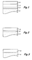
- FIG. 1 is a representation of a portion of a substrate coated with an optional bond coat layer, an optional intermediate layer, and a protective top coat layer.
- FIG. 2 is a representation of a portion of a substrate coated with an optional bond coat layer and a protective top coat layer.
- FIG. 3 is a representation of a portion of a substrate coated with a protective top coat layer.
- FIG. 4 is a flow chart depicting a method for depositing a protective coating on a complex-shaped substrate.
- FIGS. 5A and 5B show two silicon nitride ceramic integral components coated using an yttrium silicate slurry.
- FIG. 6A and 6B show SEM images of cross-sections of vertically cracked oxide coatings produced via a slurry route and FIG. 6C shows an SEM image of a highly porous oxide ceramic coating produced via a slurry route.
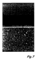
- FIG. 7 shows SEM images of a cross-section of yttria stabilized zirconia slurry based coating on a bondcoat produced using microwave assisted heating.
- FIG. 8 shows a time temperature profile for plasma arc sintering of a YSZ coated NiO disk.
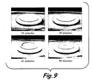
- FIG. 9 shows the densification sequence for a YSZ coated NiO disk during sintering.
- the present invention relates to methods for applying a protective coating to complex shaped parts.
- the protective coating may serve as a thermal barrier coating on superalloy components exposed to high temperature combustion environments, or as an environmental barrier coating on silicon based components exposed to high temperature combustion environments.
- complex shaped part means a part whose shape and geometry are not conducive to being coated by conventional line-of-sight methods known to one of ordinary skill in the art.
- complex shaped parts may be coated using the methods of the present invention.
- aircraft engine manufacturers may utilize the methods of the present invention to coat complex shaped parts such as vanes, rotors, blades, combustor liners, shrouds, transition ducts, airfoils, and substantially tubular gas turbine engine components and integrally bladed rotors.
- complex shaped turbine engine and turbomachinery components may be coated using the methods of the present invention.
- an integral vane assembly which consists of a set of 8 to 20 vanes with integral outer and inner platforms may also be coated using the methods of the present invention.
- the substrate 10 may comprise a ceramic material, a metal based material, combinations comprising at least one of the foregoing and the like.
- the substrate may comprise nickel based, cobalt based or iron based superalloys or silicon based ceramic turbine materials such as silicon nitride or silicon carbide.
- the substrates may also include austenitic and ferritic grade steels and ceramic matrix composites in need of environmental/thermal protection.
- a bondcoat layer 12 may optionally be disposed onto the surface of substrate 10.
- Bondcoat layer 12 may comprise at least one metal based composition or one ceramic based composition suitable for use with the substrate materials.
- An intermediate layer 14 may optionally be disposed onto the bondcoat layer 12.
- Intermediate layer 14 may comprise at least one metal based composition or one ceramic based composition suitable for use with the substrate materials.
- a protective layer 16 may be disposed upon the substrate 10 or, if present, upon the bondcoat layer 12 or the intermediate layer 14.
- the protective layer 16 may comprise at least one refractory metal oxide. Any refractory metal oxide may be employed.
- the protective layer 16 may further comprise up to about 50 mole percent of at least one other refractory metal oxide.
- the methods for applying the protective coatings described herein improve the overall adhesion and uniformity of the protective coatings upon the substrate.
- the methods may be described in a series of steps, some of which may be optional and whose order may be changed dependent upon factors such as, but not limited to, the intended application, process conditions, and the like.
- the method generally comprises providing a substrate as described above at step 20 in FIG. 4 .
- the substrate may include an optional bondcoat layer 12 disposed between the substrate 10 and the aforementioned optional intermediate layer 14 as shown at step 30 in FIG. 4 .
- the optional intermediate layer 14 may be disposed between the optional bondcoat layer 12 and the aforementioned protective layer 16 or between the substrate 10 and the aforementioned bondcoat layer 12 as shown at step 40 in FIG. 4 .
- the optional bondcoat layer 12 may be applied to the substrate 10 by any suitable manner known in the art such as, but not limited to, thermal spraying, slurry coating, vapor deposition (chemical and physical), combinations comprising at least one of the foregoing methods and the like.
- the optional intermediate layer 14 may also be applied to the substrate 10 or optional bondcoat layer 12 by the same methods and combinations as known in the art.
- the final protective layer 16 is applied as shown at step 50 in FIG. 4 .
- the final barrier coating whether it be a thermal barrier coat (TBC) on a metallic substrate or an environmental barrier coat (EBC) on a ceramic substrate is preferably applied using a slurry dip coating technique, a painting technique or a spraying technique.
- the slurry dip coating technique generally comprises dipping the substrate with or without the optional bondcoat layer 12 and intermediate layer 14 into a slurry.
- the painting technique generally comprises applying the slurry to the substrate with a brush that has been dipped into the slurry.
- the spraying technique generally comprises spraying the slurry onto the substrate under pressure through a nozzle.
- the slurry may comprise a powder of the coating material or a precursor of the coating material , other additives in powder form that enhance adhesion to the substrate and/or alter the microstructure of the final coating, and a liquid carrier.
- the coating is thermally activated as shown in step 70 in FIG. 4 .
- This can be accomplished with a furnace or kiln in air or controlled environment using methods known to those skilled in the art.
- the inventive techniques of microwave assisted or plasma arc assisted thermal treatment are used as an embodiment of this invention.
- the final step in the process is a cool down, step 80.
- Slurry based coating processes are extremely versatile. Metal based and ceramic based bondcoats and intermediate coats as well as thermal barrier and environmental barrier coats can all be applied as slurries.
- the chemistry of the coatings can be controlled by the ingredients added to the slurry.
- the structures of the coatings can be controlled by the ingredients and the processing. For instance, density can be controlled through the addition of sacrificial pore formers or hollow ceramic spheres.
- coatings can be created with segmented and/or vertically cracked microstructures as needed. Examples of controlled microstructures and slurry based coatings will be shown below.
- Slurry based thermal barrier coatings and environmental barrier coatings need to be processed to temperatures above at least about 2400°F (1315°C) to about 2600°F (1426°C) to generate microstructures with acceptable strength and erosion resistance. Since silicon based components can withstand these temperatures, the coatings on these components are routinely fired at these temperatures after application. With superalloy components, on the other hand, the firing temperatures are excessive. Heating superalloys above about 2100°F (1148°C) for extended periods of time results in loss of properties due to severe overaging of the alloys. Also, powder forms of most ceramics of interest for use as thermal barrier coatings and metals, when sintered at temperatures below about 2100°F (1148°C), do not possess acceptable densities to provide the function required of them.
- Microwave processing is a relatively mature technology and its use in the heating and sintering of ceramics and powder metals has been recognized. While ceramic and metal powder processing using microwaves has been the subject of numerous publications (e.g., " Microwave Processing of Ceramic Composites and Metallic Materials", D. Agrawal et al., in Microwave Solutions for Ceramic Engineers, Eds. D.D.E. Clark et al., Am. Ceram. Soc. Publ. pp. 205-228 (2005 )), it has not yet been exploited for thermal or environmental barrier coating processing.
- the primary technical advantage of using microwave heating is that a dense (e.g. monolithic) metal substrate generally reflects microwave energy and therefore the metal part does not directly couple to the input energy.
- Metal and ceramic powders absorb microwave radiation and can be heated to temperatures in excess of about 2600°F (1426°C). It is therefore possible to heat the protective coating without detrimental overheating of the substrate.
- FIGS. 5A and 5B Silicon nitride integral ceramic components with complex shapes are shown in FIGS. 5A and 5B .
- the photo on the left ( FIG. 5A ) is a silicon nitride vane coated with a complex yttrium silicate environmental barrier coating applied by dip coating and processed according to FIG. 4 .
- the photo on the right ( FIG. 5B ) is an integrally bladed rotor also coated with a complex yttrium silicate coating applied by dip coating and processed according to FIG. 4 .
- the coated rotor was spun to 120,000 rpm and the coating remained intact.
- FIGS. 6A and 6B show scanning electron micrographs of cross-sections of yttrium silicate environmental barrier coatings on silicon nitride substrates that were applied by dip coating.
- vertical cracks can be introduced into the coating as shown.
- the vertical cracks reduce the modulus of elasticity of the coating and allow the coating to deform without cracking during thermal cycling.
- the improved strain tolerance generally enhances coating life and retards spalling.
- FIG. 6C illustrates the high level of porosity possible in similar coatings on a silicon nitride substrate as applied by dip coating and processed according to FIG. 4 .
- FIG. 7 shows two SEM images of a cross-section of dip coated yttria stabilized zirconia (YSZ) thermal barrier coating on a bondcoat on a superalloy substrate.
- the upper photo shows a lower magnification view of the dip coated YSZ and the bondcoat.
- the substrate was dip coated in the slurry and first dried for 2 hours in a conventional furnace.
- the part was processed in a microwave assisted furnace where it was thermally heated via the furnace to about 1050°C at nominally 15°C/min, then to about 1075°C at nominally 5°C/min, then to about 1100°C at nominally 5°C/min.
- the part was held for 10 minutes in a 2kW microwave field. Only the YSZ coating and the bondcoat are visible in the photo, and it is notable that the coating has sintered to full density.
- the lower photograph shows a higher magnification SEM micrograph of the intersection between the coating, and the substrate illustrating the integrity of the coating/substrate interface.
- the example does demonstrate that full density can be achieved using microwave assisted thermal processing.
- the microstructure of slurry based coatings can be tailored by additions of binders, sacrificial pore formers and hollow ceramic spheres and the like. It is significant to note that during the microwave assisted sintering of the YSZ coating, the substrate temperature did not exceed 2050°F (1121°C). This was confirmed by a thermocouple placed on the substrate in the vicinity of the interface. It was apparent that the metal substrate reflected the microwave energy and acted as a heat sink that conducted heat away from the coating during processing.
- high density infrared heating using a plasma arc lamp can also be used to heat slurry coated unfired surfaces.
- Plasma arc heating relies on electromagnetic radiation as a mechanism for rapidly and efficiently transferring radiant heat energy.
- Highly controllable heat fluxes can be delivered to a target surface and can be optimized to bring about selective surface heating to produce a desired temperature profile.
- Oak Ridge National Laboratories has a state-of-the-art facility and experience in plasma arc sintering and has demonstrated the technology for unidirectional heating with tremendous cost savings through reduced processing time, reduced operating cost, and environmental friendliness. T. R.
- the time temperature profile of the sintering process is shown in FIG. 8 . Photographs taken during processing are shown in FIG. 9 . The densification during sintering is evident. Normal sintering time for the YSZ-NiO structure is about 36 hours. The speed and efficiency of plasma arc lamp thermal processing are evident.
- slurry routes can be combined with chemical precursor methods such as sol-gel, to achieve improved coatings.
- Surface preparation, surface pretreatment, sintering atmosphere and other conditions can also be varied to further improve adhesion and densification characteristics.
- the coatings may be processed in vacuum or an inert atmosphere with flowing N 2 or Ar gases to reduce oxidation of the bond coat. If using air or inert gas it is also possible to induce chemical reactions between the layers to improve adhesion.
- sol-gel precursors such as metal salts (nitrates, acetates, alkoxides etc.), metal organic compounds (e.g.
- metal alkoxides in a slurry might also serve to improve the coating characteristics.
- Colloidal dispersions of metal oxides such as silica, alumina or zirconia may be used to improve reactivity of the slurry and densification characteristics of the resulting coatings.
Landscapes
- Chemical & Material Sciences (AREA)
- Engineering & Computer Science (AREA)
- Ceramic Engineering (AREA)
- Materials Engineering (AREA)
- Organic Chemistry (AREA)
- Inorganic Chemistry (AREA)
- Chemical Kinetics & Catalysis (AREA)
- Mechanical Engineering (AREA)
- Metallurgy (AREA)
- Structural Engineering (AREA)
- Other Surface Treatments For Metallic Materials (AREA)
- Turbine Rotor Nozzle Sealing (AREA)
Abstract
Description
- This invention relates to low cost, high temperature protective coatings in general and particularly to coatings on parts difficult to coat by line-of-sight techniques.
- Components within the hot gas path of a gas turbine engine are necessarily protected by a thermal barrier coating (TBC) system. TBC systems on nickel based, cobalt based and iron based superalloy turbine components include a thermal insulating ceramic top coat, referred to as the TBC, typically bonded to the component with an environmentally protective bond coat. Bond coat materials widely used in TBC systems include overlay coatings such as MCrAlX (where M is nickel, cobalt and/or iron, and X is yttrium or another rare earth or reactive element such as hafnium, zirconium, etc.) and diffusion coatings such as diffusion aluminides, notable examples of which are NiAl and NiAl(Pt). Ceramic materials and particularly binary yttria stabilized zirconia are widely used as TBC materials because of their high temperature capability, low thermal conductivity, and relative ease of deposition by plasma spraying, flame spraying and physical vapor deposition (PVD) particularly electron beam physical vapor deposition (EBPVD) techniques.
- Similar systems called environmental barrier coatings (EBCs) are also required on silicon based ceramic gas turbine components such as silicon nitride and silicon carbide in order to protect the base materials from water vapor. At high temperatures water vapor will cause the formation of volatile Si species such as Si(OH)x and SiO and result in material loss. EBC examples for ceramic turbine components include barium strontium alumino silicates (BSAS) and other alkaline earth alumino silicates as well as rare earth silicates and mullite. Bond coat materials widely used in EBC systems on silicon based substrates include layers of silicon, aluminosilicates, mullite, and rare earth silicates. Intermediate layers between the EBC and the bond coat are sometimes employed to moderate thermal expansion mismatch. EBC layers are typically deposited by air and vacuum plasma spraying (APS, VPS), high velocity oxyfuel (HVOF) spraying, chemical vapor deposition (CVD) and physical vapor deposition (PVD).
- Many of the parts in gas turbine engine systems that require thermal and environmental protective coatings have complex shapes that are difficult to coat by conventional line-of-sight methods such as thermal spray and EBPVD. Examples of complex shaped parts in aircraft engines include vanes, rotors, blades, combustor liners, shrouds, transition ducts, airfoils, tubular gas turbine components, integral vane rings, and integrally bladed rotors. Coating complex shaped parts by line-of-sight processes is time consuming and expensive.
- Non-line-of-sight coating processes are needed to increase throughput and decrease costs. Chemical vapor processes have been used but are expensive, slow and require a great deal of process development and operator skill, especially for coating large parts.
- Consequently, there exists a need for a cost effective process for preparing and applying coatings that act as barriers to corrosive environments providing a thermal and environmental barrier function and extending the service life of complex shaped parts in all applicable industries. Additionally, the desire to decrease cost, improve versatility and throughput is also a need in the industries.
- The present invention relates to processes suitable for the deposition of protective coatings on complex shaped substrates. The substrates may include, for example, nickel based, cobalt based or iron based superalloys and silicon based substrates which are used in articles and structures subjected to high temperature environments with water vapor present.
- The processes of the present invention include lower cost non-line of sight processes and particularly dip coating, painting and spraying. Dip coating, painting and spraying can be used to deposit slurries containing a dispersion of particles of a protective coating or of precursors to a protective coating and other additives contributing to the properties of the final coating in a suitable liquid carrier. The dried, green deposited layers can be a bondcoat, a thermal barrier coat (TBC), an environmental barrier coat (EBC), a topcoat, and/or an intermediate layer coat.
- In cases where the thermal treatment temperatures of the coating(s) would be high enough to be detrimental to metallic (e.g. superalloy) substrates, thermal treatment can be accomplished using alternate energy sources such as microwave energy or plasma arc energy.
-
FIG. 1 is a representation of a portion of a substrate coated with an optional bond coat layer, an optional intermediate layer, and a protective top coat layer. -
FIG. 2 is a representation of a portion of a substrate coated with an optional bond coat layer and a protective top coat layer. -
FIG. 3 is a representation of a portion of a substrate coated with a protective top coat layer. -
FIG. 4 is a flow chart depicting a method for depositing a protective coating on a complex-shaped substrate. -
FIGS. 5A and 5B show two silicon nitride ceramic integral components coated using an yttrium silicate slurry. -
FIG. 6A and 6B show SEM images of cross-sections of vertically cracked oxide coatings produced via a slurry route andFIG. 6C shows an SEM image of a highly porous oxide ceramic coating produced via a slurry route. -
FIG. 7 shows SEM images of a cross-section of yttria stabilized zirconia slurry based coating on a bondcoat produced using microwave assisted heating. -
FIG. 8 shows a time temperature profile for plasma arc sintering of a YSZ coated NiO disk. -
FIG. 9 shows the densification sequence for a YSZ coated NiO disk during sintering. - The present invention relates to methods for applying a protective coating to complex shaped parts. The protective coating may serve as a thermal barrier coating on superalloy components exposed to high temperature combustion environments, or as an environmental barrier coating on silicon based components exposed to high temperature combustion environments.
- Referring to
FIGS. 1-3 , a portion of a complex shaped part is represented by asubstrate 10. As used herein, the term "complex shaped part" means a part whose shape and geometry are not conducive to being coated by conventional line-of-sight methods known to one of ordinary skill in the art. Various industries employ complex shaped parts, and all of these complex shaped parts may be coated using the methods of the present invention. For example, aircraft engine manufacturers may utilize the methods of the present invention to coat complex shaped parts such as vanes, rotors, blades, combustor liners, shrouds, transition ducts, airfoils, and substantially tubular gas turbine engine components and integrally bladed rotors. Many other complex shaped turbine engine and turbomachinery components may be coated using the methods of the present invention. For example, an integral vane assembly which consists of a set of 8 to 20 vanes with integral outer and inner platforms may also be coated using the methods of the present invention. - Generally, the
substrate 10 may comprise a ceramic material, a metal based material, combinations comprising at least one of the foregoing and the like. For example, the substrate may comprise nickel based, cobalt based or iron based superalloys or silicon based ceramic turbine materials such as silicon nitride or silicon carbide. The substrates may also include austenitic and ferritic grade steels and ceramic matrix composites in need of environmental/thermal protection. - Referring again to
FIGS. 1-3 abondcoat layer 12 may optionally be disposed onto the surface ofsubstrate 10.Bondcoat layer 12 may comprise at least one metal based composition or one ceramic based composition suitable for use with the substrate materials. Anintermediate layer 14 may optionally be disposed onto thebondcoat layer 12.Intermediate layer 14 may comprise at least one metal based composition or one ceramic based composition suitable for use with the substrate materials. Aprotective layer 16 may be disposed upon thesubstrate 10 or, if present, upon thebondcoat layer 12 or theintermediate layer 14. Theprotective layer 16 may comprise at least one refractory metal oxide. Any refractory metal oxide may be employed. In addition, theprotective layer 16 may further comprise up to about 50 mole percent of at least one other refractory metal oxide. - Referring to
FIG. 4 , the methods for applying the protective coatings described herein improve the overall adhesion and uniformity of the protective coatings upon the substrate. For purposes of illustration and not to be taken in a limiting sense, the methods may be described in a series of steps, some of which may be optional and whose order may be changed dependent upon factors such as, but not limited to, the intended application, process conditions, and the like. The method generally comprises providing a substrate as described above atstep 20 inFIG. 4 . The substrate may include anoptional bondcoat layer 12 disposed between thesubstrate 10 and the aforementioned optionalintermediate layer 14 as shown atstep 30 inFIG. 4 . The optionalintermediate layer 14 may be disposed between theoptional bondcoat layer 12 and the aforementionedprotective layer 16 or between thesubstrate 10 and theaforementioned bondcoat layer 12 as shown atstep 40 inFIG. 4 . - The
optional bondcoat layer 12 may be applied to thesubstrate 10 by any suitable manner known in the art such as, but not limited to, thermal spraying, slurry coating, vapor deposition (chemical and physical), combinations comprising at least one of the foregoing methods and the like. The optionalintermediate layer 14 may also be applied to thesubstrate 10 oroptional bondcoat layer 12 by the same methods and combinations as known in the art. - The final
protective layer 16 is applied as shown atstep 50 inFIG. 4 . The final barrier coating, whether it be a thermal barrier coat (TBC) on a metallic substrate or an environmental barrier coat (EBC) on a ceramic substrate is preferably applied using a slurry dip coating technique, a painting technique or a spraying technique. The slurry dip coating technique generally comprises dipping the substrate with or without theoptional bondcoat layer 12 andintermediate layer 14 into a slurry. The painting technique generally comprises applying the slurry to the substrate with a brush that has been dipped into the slurry. The spraying technique generally comprises spraying the slurry onto the substrate under pressure through a nozzle. The slurry may comprise a powder of the coating material or a precursor of the coating material , other additives in powder form that enhance adhesion to the substrate and/or alter the microstructure of the final coating, and a liquid carrier. - Following drying (step 60), the coating is thermally activated as shown in
step 70 inFIG. 4 . This can be accomplished with a furnace or kiln in air or controlled environment using methods known to those skilled in the art. In the case where the firing temperature of a ceramic containing TBC would be detrimental to the substrate, as discussed below, the inventive techniques of microwave assisted or plasma arc assisted thermal treatment are used as an embodiment of this invention. The final step in the process is a cool down,step 80. - Slurry based coating processes are extremely versatile. Metal based and ceramic based bondcoats and intermediate coats as well as thermal barrier and environmental barrier coats can all be applied as slurries. The chemistry of the coatings can be controlled by the ingredients added to the slurry. The structures of the coatings can be controlled by the ingredients and the processing. For instance, density can be controlled through the addition of sacrificial pore formers or hollow ceramic spheres. By varying the drying conditions, coatings can be created with segmented and/or vertically cracked microstructures as needed. Examples of controlled microstructures and slurry based coatings will be shown below.
- Slurry based thermal barrier coatings and environmental barrier coatings need to be processed to temperatures above at least about 2400°F (1315°C) to about 2600°F (1426°C) to generate microstructures with acceptable strength and erosion resistance. Since silicon based components can withstand these temperatures, the coatings on these components are routinely fired at these temperatures after application. With superalloy components, on the other hand, the firing temperatures are excessive. Heating superalloys above about 2100°F (1148°C) for extended periods of time results in loss of properties due to severe overaging of the alloys. Also, powder forms of most ceramics of interest for use as thermal barrier coatings and metals, when sintered at temperatures below about 2100°F (1148°C), do not possess acceptable densities to provide the function required of them. While the increased porosity in the coatings sintered at these temperatures is often desirable to reduce thermal conductivity, the highly porous structure has unacceptably poor erosion resistance. This invention proposes unique and non-traditional approaches for heating slurry-based, green thermal and environmental barrier coatings without significant heating of the substrate, therefore avoiding the associated risk. Layered approaches where porous inner layers for thermal insulation are capped using dense outer layers for erosion/corrosion protection are possible using the processes described herein.
- Two approaches are proposed to ensure that the green, unfired coating applied as slurries can sinter and adhere to the substrate without causing any damage to the mechanical properties of the substrate. These approaches are microwave heating and plasma arc lamp heating. It should be emphasized that in addition to ceramic top coats, metallic bond coats may also be deposited using the slurry approaches described above and post processing approaches described herein.
- Microwave processing is a relatively mature technology and its use in the heating and sintering of ceramics and powder metals has been recognized. While ceramic and metal powder processing using microwaves has been the subject of numerous publications (e.g., "Microwave Processing of Ceramic Composites and Metallic Materials", D. Agrawal et al., in Microwave Solutions for Ceramic Engineers, Eds. D.D.E. Clark et al., Am. Ceram. Soc. Publ. pp. 205-228 (2005)), it has not yet been exploited for thermal or environmental barrier coating processing. The primary technical advantage of using microwave heating is that a dense (e.g. monolithic) metal substrate generally reflects microwave energy and therefore the metal part does not directly couple to the input energy. Metal and ceramic powders, on the other hand absorb microwave radiation and can be heated to temperatures in excess of about 2600°F (1426°C). It is therefore possible to heat the protective coating without detrimental overheating of the substrate.
- EXAMPLE 1. Silicon nitride integral ceramic components with complex shapes are shown in
FIGS. 5A and 5B . The photo on the left (FIG. 5A ) is a silicon nitride vane coated with a complex yttrium silicate environmental barrier coating applied by dip coating and processed according toFIG. 4 . The photo on the right (FIG. 5B ) is an integrally bladed rotor also coated with a complex yttrium silicate coating applied by dip coating and processed according toFIG. 4 . The coated rotor was spun to 120,000 rpm and the coating remained intact. - EXAMPLE 2. Microstructural control can be achieved in slurry based coatings.
FIGS. 6A and 6B show scanning electron micrographs of cross-sections of yttrium silicate environmental barrier coatings on silicon nitride substrates that were applied by dip coating. By controlling the drying and curing process, vertical cracks can be introduced into the coating as shown. The vertical cracks reduce the modulus of elasticity of the coating and allow the coating to deform without cracking during thermal cycling. The improved strain tolerance generally enhances coating life and retards spalling. -
FIG. 6C illustrates the high level of porosity possible in similar coatings on a silicon nitride substrate as applied by dip coating and processed according toFIG. 4 . - EXAMPLE 3. Slurry based ceramic thermal barrier coatings have been shown to densify on superalloy substrates by microwave assisted heating without degrading the properties of the substrate.
FIG. 7 shows two SEM images of a cross-section of dip coated yttria stabilized zirconia (YSZ) thermal barrier coating on a bondcoat on a superalloy substrate. The upper photo shows a lower magnification view of the dip coated YSZ and the bondcoat. To form the coating the substrate was dip coated in the slurry and first dried for 2 hours in a conventional furnace. Following drying the part was processed in a microwave assisted furnace where it was thermally heated via the furnace to about 1050°C at nominally 15°C/min, then to about 1075°C at nominally 5°C/min, then to about 1100°C at nominally 5°C/min. When 1100°C was reached, the part was held for 10 minutes in a 2kW microwave field. Only the YSZ coating and the bondcoat are visible in the photo, and it is notable that the coating has sintered to full density. The lower photograph shows a higher magnification SEM micrograph of the intersection between the coating, and the substrate illustrating the integrity of the coating/substrate interface. Although a fully dense thermal barrier coating is not a desirable structure from a thermal conductivity standpoint, the example does demonstrate that full density can be achieved using microwave assisted thermal processing. As noted earlier, the microstructure of slurry based coatings can be tailored by additions of binders, sacrificial pore formers and hollow ceramic spheres and the like. It is significant to note that during the microwave assisted sintering of the YSZ coating, the substrate temperature did not exceed 2050°F (1121°C). This was confirmed by a thermocouple placed on the substrate in the vicinity of the interface. It was apparent that the metal substrate reflected the microwave energy and acted as a heat sink that conducted heat away from the coating during processing. - In addition to microwave processing, high density infrared heating using a plasma arc lamp can also be used to heat slurry coated unfired surfaces. Plasma arc heating relies on electromagnetic radiation as a mechanism for rapidly and efficiently transferring radiant heat energy. Highly controllable heat fluxes can be delivered to a target surface and can be optimized to bring about selective surface heating to produce a desired temperature profile. Oak Ridge National Laboratories has a state-of-the-art facility and experience in plasma arc sintering and has demonstrated the technology for unidirectional heating with tremendous cost savings through reduced processing time, reduced operating cost, and environmental friendliness. T. R. Armstrong et al., "Economical Thermal Processing of Solid Oxide Membrane Materials", Proceedings, 16th Annual Conference on Fossil Energy Materials, April 22-24, National Energy Technology Laboratory, Oak Ridge, TN (2002). The primary drawback of the arc heating approach is the potential requirements of complex sample manipulation to access hidden (non-line-of-sight) areas. An example taken from the Armstrong et al. article illustrates the efficiency of plasma arc lamp thermal processing. The plasma arc lamp was used to sinter an yttria stabilized zirconia (YSZ) powder coating on a cast porous nickel oxide (NiO) powder substrate. The densified YSZ layer acts as a solid electrolyte and the NiO base is an electrode. The time temperature profile of the sintering process is shown in
FIG. 8 . Photographs taken during processing are shown inFIG. 9 . The densification during sintering is evident. Normal sintering time for the YSZ-NiO structure is about 36 hours. The speed and efficiency of plasma arc lamp thermal processing are evident. - In addition to the proposed non-conventional heating approaches, other processing variables can be adjusted. For example, slurry routes can be combined with chemical precursor methods such as sol-gel, to achieve improved coatings. Surface preparation, surface pretreatment, sintering atmosphere and other conditions can also be varied to further improve adhesion and densification characteristics. For example, the coatings may be processed in vacuum or an inert atmosphere with flowing N2 or Ar gases to reduce oxidation of the bond coat. If using air or inert gas it is also possible to induce chemical reactions between the layers to improve adhesion. The use of sol-gel precursors such as metal salts (nitrates, acetates, alkoxides etc.), metal organic compounds (e.g. metal alkoxides) in a slurry might also serve to improve the coating characteristics. Colloidal dispersions of metal oxides such as silica, alumina or zirconia may be used to improve reactivity of the slurry and densification characteristics of the resulting coatings.
- Although the present invention has been described with reference to preferred embodiments, workers skilled in the art will recognize that changes may be made in form and detail without departing from the scope of the invention, which is defined by the claims and their equivalents.
Claims (15)
- A method for depositing a first protective coating upon the surface of complex-shaped components, designed to operate at temperatures exceeding 2000°F (1093°C), the method comprising:providing (20) a complex-shaped component;applying (50) a slurry to the complex-shaped component to deposit a green coating, the slurry including a fluid carrier containing a dispersion of particles of a protective coating or of precursors of the protective coating and other additives contributing to the properties of the coating;drying (60) the green coating; andthermally activating (70) the dried coating to result in a sintered and well-adhered protective coating.
- The method of claim 1, wherein the slurry is applied by dip coating.
- The method of claim 1, wherein the slurry is applied by at least one of painting or spraying.
- The method of claim 1, 2 or 3, wherein the coating is at least one of a metallic or ceramic coating.
- A method of coating a turbine component with a protective coating, the method comprising:applying (50) a slurry to the turbine component, the slurry comprising a fluid carrier containing a dispersion of particles or precursors of the protective coating;drying (60) the slurry applied to the turbine component; andthermally activating (70) the dried slurry to result in a sintered and well-adhered protective coating on the turbine component.
- The method of claim 5 wherein said article has a complex shape.
- The method of any preceding claim wherein said component is a component of a gas turbine engine.
- The method of claim 7 wherein said component comprises at least one of a vane, a rotor, a blade, a combustor liner, a shroud, a transition duct, an airfoil, a tubular component, an integrally bladed rotor, and an integrally bladed vane.
- The method of any preceding claim wherein a first slurry-based protective coating (30) is a bond coat and a second slurry based protective coating (50) is a Thermal Barrier Coat (TBC) or an Environmental Barrier Coat (EBC).
- The method of claim 9 wherein a slurry-based intermediate layer is positioned (40) between the bond coat and the thermal barrier coat.
- The method of claim 10 wherein a slurry-based top coat is positioned on top of the thermal barrier coat.
- The method of any preceding claim wherein the coating is thermally activated (70) by microwave energy.
- The method of any of claims 1 to 11 wherein the coating is thermally activated (70) by high energy plasma arc infrared energy.
- The method of any preceding claim wherein the component is formed of at least one of a nickel-based, cobalt-based, or iron-based superalloy.
- The method of any of claims 1 to 14 wherein the component is formed of a material comprising at least one of silicon carbide or silicon nitride.
Applications Claiming Priority (1)
| Application Number | Priority Date | Filing Date | Title |
|---|---|---|---|
| US12/150,780 US20090274850A1 (en) | 2008-05-01 | 2008-05-01 | Low cost non-line-of -sight protective coatings |
Publications (2)
| Publication Number | Publication Date |
|---|---|
| EP2113586A2 true EP2113586A2 (en) | 2009-11-04 |
| EP2113586A3 EP2113586A3 (en) | 2010-05-12 |
Family
ID=40845993
Family Applications (1)
| Application Number | Title | Priority Date | Filing Date |
|---|---|---|---|
| EP09251003A Withdrawn EP2113586A3 (en) | 2008-05-01 | 2009-03-31 | Low cost non-line-of-sight portective coatings |
Country Status (2)
| Country | Link |
|---|---|
| US (1) | US20090274850A1 (en) |
| EP (1) | EP2113586A3 (en) |
Families Citing this family (30)
| Publication number | Priority date | Publication date | Assignee | Title |
|---|---|---|---|---|
| US20090294566A1 (en) * | 2008-05-30 | 2009-12-03 | General Electric Company | Methods for spiral winding composite fan bypass ducts and other like components |
| US20090294567A1 (en) * | 2008-05-30 | 2009-12-03 | General Electric Company | Spiral winding systems for manufacturing composite fan bypass ducts and other like components |
| DE102009023628A1 (en) * | 2009-05-27 | 2010-12-02 | Siemens Aktiengesellschaft | A method of forming a layer of absorber particles for energy radiation |
| US20110027467A1 (en) * | 2009-07-31 | 2011-02-03 | Glen Harold Kirby | Methods of making environmental barrier coatings for high temperature ceramic components using sintering aids |
| US8501840B2 (en) * | 2009-07-31 | 2013-08-06 | General Electric Company | Water based slurry compositions for making environmental barrier coatings and environmental barrier coatings comprising the same |
| US20110027517A1 (en) * | 2009-07-31 | 2011-02-03 | Glen Harold Kirby | Methods of improving surface roughness of an environmental barrier coating and components comprising environmental barrier coatings having improved surface roughness |
| US9212100B2 (en) | 2009-07-31 | 2015-12-15 | General Electric Company | Environmental barrier coatings for high temperature ceramic components |
| US9023435B2 (en) | 2009-07-31 | 2015-05-05 | General Electric Company | Methods for making water based environmental barrier coatings using sintering aids |
| US20110027559A1 (en) | 2009-07-31 | 2011-02-03 | Glen Harold Kirby | Water based environmental barrier coatings for high temperature ceramic components |
| US9062564B2 (en) * | 2009-07-31 | 2015-06-23 | General Electric Company | Solvent based slurry compositions for making environmental barrier coatings and environmental barrier coatings comprising the same |
| US20110027557A1 (en) * | 2009-07-31 | 2011-02-03 | Glen Harold Kirby | Solvent based environmental barrier coatings for high temperature ceramic components |
| US9005717B2 (en) * | 2009-07-31 | 2015-04-14 | General Electric Company | Methods for making environmental barrier coatings using sintering aids |
| US8673400B2 (en) * | 2009-07-31 | 2014-03-18 | General Electric Company | Methods of improving surface roughness of an environmental barrier coating and components comprising environmental barrier coatings having improved surface roughness |
| US9005716B2 (en) * | 2009-07-31 | 2015-04-14 | General Electric Company | Method for making solvent based environmental barrier coatings using sintering aids |
| US8986779B2 (en) * | 2009-07-31 | 2015-03-24 | General Electric Company | Methods of improving surface roughness of an environmental barrier coating and components comprising environmental barrier coatings having improved surface roughness |
| US9073793B2 (en) * | 2009-07-31 | 2015-07-07 | General Electric Company | Slurry compositions for making environmental barrier coatings and environmental barrier coatings comprising the same |
| US8999457B2 (en) * | 2009-07-31 | 2015-04-07 | General Electric Company | Methods for making environmental barrier coatings using sintering aids |
| US9056802B2 (en) | 2009-07-31 | 2015-06-16 | General Electric Company | Methods for making environmental barrier coatings using sintering aids |
| MX2013010300A (en) * | 2011-03-10 | 2014-04-30 | Mesocoat Inc | Method and apparatus for forming clad metal products. |
| US20160208371A1 (en) * | 2013-08-27 | 2016-07-21 | Agency For Science, Technology And Research | Method of treating a thermal barrier coating |
| WO2015053938A1 (en) | 2013-10-10 | 2015-04-16 | United Technologies Corporation | Controlling microstructure of inorganic material by indirect heating using electromagnetic radiation |
| US9890089B2 (en) | 2014-03-11 | 2018-02-13 | General Electric Company | Compositions and methods for thermal spraying a hermetic rare earth environmental barrier coating |
| US20170009328A1 (en) * | 2015-07-10 | 2017-01-12 | General Electric Company | Coating process and coated component |
| US10384978B2 (en) | 2016-08-22 | 2019-08-20 | General Electric Company | Thermal barrier coating repair compositions and methods of use thereof |
| US10774006B2 (en) | 2017-05-10 | 2020-09-15 | Applied Materials, Inc. | Microwave and induction heat treatment of ceramic coatings |
| US11827574B2 (en) * | 2018-09-14 | 2023-11-28 | Honeywell International Inc. | Method of pressure sintering an environmental barrier coating on a surface of a ceramic substrate |
| US12358845B2 (en) * | 2020-04-15 | 2025-07-15 | General Electric Company | Consumable coatings and methods of protecting a high temperature component from dust deposits |
| US12227464B2 (en) * | 2021-05-18 | 2025-02-18 | Rolls-Royce Corporation | CMAS-resistant environmental barrier coating system |
| US12448336B2 (en) | 2022-02-07 | 2025-10-21 | General Electric Company | Bond coat including metal oxides and oxygen getters |
| WO2026035826A1 (en) * | 2024-08-06 | 2026-02-12 | Rtx Corporation | Hybrid coating for enhanced cmas resistance of thermal barrier coating |
Citations (6)
| Publication number | Priority date | Publication date | Assignee | Title |
|---|---|---|---|---|
| WO2005071141A1 (en) | 2004-01-22 | 2005-08-04 | The University Of Manchester | Ceramic coating |
| EP1626039A2 (en) | 2004-08-09 | 2006-02-15 | United Technologies Corporation | Non-line of-sight process for coating complexed shaped structures |
| US20060280952A1 (en) | 2005-06-13 | 2006-12-14 | Hazel Brian T | Bond coat for corrosion resistant EBC for silicon-containing substrate and processes for preparing same |
| WO2007087423A2 (en) | 2006-01-25 | 2007-08-02 | Ceramatec, Inc. | Environmental and thermal barrier coating to provide protection in various environments |
| EP1900840A2 (en) | 2006-09-14 | 2008-03-19 | General Electric Company | Method for preparing strain tolerant coatings from a green material |
| EP2000557A1 (en) | 2007-06-04 | 2008-12-10 | United Technologies Corporation | Erosion barrier for thermal barrier coatings |
Family Cites Families (16)
| Publication number | Priority date | Publication date | Assignee | Title |
|---|---|---|---|---|
| JPS5948873B2 (en) * | 1980-05-14 | 1984-11-29 | ペルメレック電極株式会社 | Method for manufacturing electrode substrate or electrode provided with corrosion-resistant coating |
| DE19741498B4 (en) * | 1997-09-20 | 2008-07-03 | Evonik Degussa Gmbh | Production of a ceramic stainless steel mesh composite |
| US6239079B1 (en) * | 1998-07-06 | 2001-05-29 | M. I. Topchiashvili | High temperature superconductor composite material |
| US6221522B1 (en) * | 1999-09-10 | 2001-04-24 | Siemens Westinghouse Power Corporation | Open end protection for solid oxide fuel cells |
| US6294261B1 (en) * | 1999-10-01 | 2001-09-25 | General Electric Company | Method for smoothing the surface of a protective coating |
| DE10357536B4 (en) * | 2003-12-10 | 2013-10-02 | Mtu Aero Engines Gmbh | Method of repairing thermal barrier coatings with local damage |
| DE10357535A1 (en) * | 2003-12-10 | 2005-07-07 | Mtu Aero Engines Gmbh | Ceramic material and method for repairing thermal barrier coatings with local damage |
| US7368164B2 (en) * | 2004-06-18 | 2008-05-06 | General Electric Company | Smooth outer coating for combustor components and coating method therefor |
| US7666512B2 (en) * | 2004-08-09 | 2010-02-23 | United Technologies Corporation | Thermal resistant environmental barrier coating |
| US7708184B2 (en) * | 2004-10-01 | 2010-05-04 | United Technologies Corporation | Microwave brazing of airfoil cracks |
| US7374818B2 (en) * | 2005-05-23 | 2008-05-20 | United Technologies Corporation | Coating system for silicon based substrates |
| DE102006005026A1 (en) * | 2006-02-03 | 2007-08-09 | Degussa Gmbh | Electrically conductive transparent coating production of sintered particles involves applying liquid composition with nanoparticles of electrically conductive metal oxide and dispersion agent to substrate |
| US9221720B2 (en) * | 2006-03-01 | 2015-12-29 | United Technologies Corporation | Dense protective coatings, methods for their preparation and coated articles |
| US8342386B2 (en) * | 2006-12-15 | 2013-01-01 | General Electric Company | Braze materials and processes therefor |
| US8574686B2 (en) * | 2006-12-15 | 2013-11-05 | General Electric Company | Microwave brazing process for forming coatings |
| US7749568B2 (en) * | 2007-03-05 | 2010-07-06 | United Technologies Corporation | Composite article and fabrication method |
-
2008
- 2008-05-01 US US12/150,780 patent/US20090274850A1/en not_active Abandoned
-
2009
- 2009-03-31 EP EP09251003A patent/EP2113586A3/en not_active Withdrawn
Patent Citations (6)
| Publication number | Priority date | Publication date | Assignee | Title |
|---|---|---|---|---|
| WO2005071141A1 (en) | 2004-01-22 | 2005-08-04 | The University Of Manchester | Ceramic coating |
| EP1626039A2 (en) | 2004-08-09 | 2006-02-15 | United Technologies Corporation | Non-line of-sight process for coating complexed shaped structures |
| US20060280952A1 (en) | 2005-06-13 | 2006-12-14 | Hazel Brian T | Bond coat for corrosion resistant EBC for silicon-containing substrate and processes for preparing same |
| WO2007087423A2 (en) | 2006-01-25 | 2007-08-02 | Ceramatec, Inc. | Environmental and thermal barrier coating to provide protection in various environments |
| EP1900840A2 (en) | 2006-09-14 | 2008-03-19 | General Electric Company | Method for preparing strain tolerant coatings from a green material |
| EP2000557A1 (en) | 2007-06-04 | 2008-12-10 | United Technologies Corporation | Erosion barrier for thermal barrier coatings |
Also Published As
| Publication number | Publication date |
|---|---|
| US20090274850A1 (en) | 2009-11-05 |
| EP2113586A3 (en) | 2010-05-12 |
Similar Documents
| Publication | Publication Date | Title |
|---|---|---|
| EP2113586A2 (en) | Low cost non-line-of-sight portective coatings | |
| US11878945B2 (en) | Applying silicon metal-containing bond layer to ceramic or ceramic matrix composite substrates | |
| EP1428902B1 (en) | Thermal barrier coating protected by infiltrated alumina and method for preparing same | |
| JP5554488B2 (en) | Alumina-based protective coating for thermal barrier coating | |
| EP3575559B1 (en) | Tapered abradable coatings | |
| EP3565795B1 (en) | Slurry-based methods for forming a bond coat | |
| EP1908856B1 (en) | Segmented abradable coatings and process(es) for applying the same | |
| EP1642993B1 (en) | Segmented gadolinia zirconia coatings | |
| EP1829847A2 (en) | Adhesive protective coatings, non-line of sight methods for their preparation, and coated articles | |
| EP2947173B1 (en) | Calcium magnesium aluminosilicate (cmas) resistant thermal barrier coating and coating process therefor | |
| JP2006347870A (en) | Process for producing corrosion-resistant EBC bond coats and the like for silicon-containing substrates | |
| JP2007008806A (en) | Process for producing anti-corrosive sealant and the like for external EBL of silicon-containing substrates | |
| EP3748031B1 (en) | Reflective coating and coating process therefor | |
| EP3002348B1 (en) | Process for coating gas turbine engine components comprising multi-phase pre-reacted thermal barrier coatings and coated gas turbine engine components | |
| EP4253350A1 (en) | Direct bonded environmental barrier coatings for sic/sic composites and methods for preparing the same | |
| US12617730B2 (en) | Direct bonded environmental barrier coatings for sic/sic composites and methods for preparing the same | |
| EP2423347A1 (en) | Method for forming a thermal barrier coating and a turbine component with the thermal barrier coating |
Legal Events
| Date | Code | Title | Description |
|---|---|---|---|
| PUAI | Public reference made under article 153(3) epc to a published international application that has entered the european phase |
Free format text: ORIGINAL CODE: 0009012 |
|
| AK | Designated contracting states |
Kind code of ref document: A2 Designated state(s): AT BE BG CH CY CZ DE DK EE ES FI FR GB GR HR HU IE IS IT LI LT LU LV MC MK MT NL NO PL PT RO SE SI SK TR |
|
| AX | Request for extension of the european patent |
Extension state: AL BA RS |
|
| PUAL | Search report despatched |
Free format text: ORIGINAL CODE: 0009013 |
|
| AK | Designated contracting states |
Kind code of ref document: A3 Designated state(s): AT BE BG CH CY CZ DE DK EE ES FI FR GB GR HR HU IE IS IT LI LT LU LV MC MK MT NL NO PL PT RO SE SI SK TR |
|
| AX | Request for extension of the european patent |
Extension state: AL BA RS |
|
| 17P | Request for examination filed |
Effective date: 20101112 |
|
| AKX | Designation fees paid |
Designated state(s): DE GB |
|
| 17Q | First examination report despatched |
Effective date: 20111109 |
|
| STAA | Information on the status of an ep patent application or granted ep patent |
Free format text: STATUS: THE APPLICATION IS DEEMED TO BE WITHDRAWN |
|
| 18D | Application deemed to be withdrawn |
Effective date: 20120522 |