JP5554488B2 - Alumina-based protective coating for thermal barrier coating - Google Patents
Alumina-based protective coating for thermal barrier coating Download PDFInfo
- Publication number
- JP5554488B2 JP5554488B2 JP2008270423A JP2008270423A JP5554488B2 JP 5554488 B2 JP5554488 B2 JP 5554488B2 JP 2008270423 A JP2008270423 A JP 2008270423A JP 2008270423 A JP2008270423 A JP 2008270423A JP 5554488 B2 JP5554488 B2 JP 5554488B2
- Authority
- JP
- Japan
- Prior art keywords
- alumina
- coating
- thermal barrier
- barrier coating
- stabilized zirconia
- Prior art date
- Legal status (The legal status is an assumption and is not a legal conclusion. Google has not performed a legal analysis and makes no representation as to the accuracy of the status listed.)
- Active
Links
- 239000012720 thermal barrier coating Substances 0.000 title claims description 99
- PNEYBMLMFCGWSK-UHFFFAOYSA-N aluminium oxide Inorganic materials [O-2].[O-2].[O-2].[Al+3].[Al+3] PNEYBMLMFCGWSK-UHFFFAOYSA-N 0.000 title claims description 71
- 239000011253 protective coating Substances 0.000 title description 3
- 238000000576 coating method Methods 0.000 claims description 67
- 239000011248 coating agent Substances 0.000 claims description 61
- 238000000034 method Methods 0.000 claims description 34
- 239000000356 contaminant Substances 0.000 claims description 20
- 239000000843 powder Substances 0.000 claims description 19
- 229910052751 metal Inorganic materials 0.000 claims description 18
- 239000002184 metal Substances 0.000 claims description 18
- 229910045601 alloy Inorganic materials 0.000 claims description 14
- 239000000956 alloy Substances 0.000 claims description 14
- 239000000463 material Substances 0.000 claims description 13
- 230000008018 melting Effects 0.000 claims description 11
- 238000002844 melting Methods 0.000 claims description 11
- 239000000203 mixture Substances 0.000 claims description 11
- 238000005507 spraying Methods 0.000 claims description 11
- MCMNRKCIXSYSNV-UHFFFAOYSA-N Zirconium dioxide Chemical compound O=[Zr]=O MCMNRKCIXSYSNV-UHFFFAOYSA-N 0.000 claims description 10
- 238000000151 deposition Methods 0.000 claims description 9
- 229910002076 stabilized zirconia Inorganic materials 0.000 claims description 8
- 230000003746 surface roughness Effects 0.000 claims description 7
- GWEVSGVZZGPLCZ-UHFFFAOYSA-N Titan oxide Chemical compound O=[Ti]=O GWEVSGVZZGPLCZ-UHFFFAOYSA-N 0.000 claims description 6
- CMIHHWBVHJVIGI-UHFFFAOYSA-N gadolinium(iii) oxide Chemical compound [O-2].[O-2].[O-2].[Gd+3].[Gd+3] CMIHHWBVHJVIGI-UHFFFAOYSA-N 0.000 claims description 6
- 238000007750 plasma spraying Methods 0.000 claims description 6
- 229910001233 yttria-stabilized zirconia Inorganic materials 0.000 claims description 5
- -1 calcium-magnesium-aluminum-silicon Chemical compound 0.000 claims description 4
- 238000010438 heat treatment Methods 0.000 claims description 3
- 241000968352 Scandia <hydrozoan> Species 0.000 claims description 2
- 229910002084 calcia-stabilized zirconia Inorganic materials 0.000 claims description 2
- 238000010285 flame spraying Methods 0.000 claims description 2
- 229910002085 magnesia-stabilized zirconia Inorganic materials 0.000 claims description 2
- HJGMWXTVGKLUAQ-UHFFFAOYSA-N oxygen(2-);scandium(3+) Chemical compound [O-2].[O-2].[O-2].[Sc+3].[Sc+3] HJGMWXTVGKLUAQ-UHFFFAOYSA-N 0.000 claims description 2
- CSDREXVUYHZDNP-UHFFFAOYSA-N alumanylidynesilicon Chemical compound [Al].[Si] CSDREXVUYHZDNP-UHFFFAOYSA-N 0.000 claims 1
- ZFXVRMSLJDYJCH-UHFFFAOYSA-N calcium magnesium Chemical compound [Mg].[Ca] ZFXVRMSLJDYJCH-UHFFFAOYSA-N 0.000 claims 1
- 239000010410 layer Substances 0.000 description 29
- 239000000758 substrate Substances 0.000 description 25
- 239000007789 gas Substances 0.000 description 18
- 230000008569 process Effects 0.000 description 10
- 239000007921 spray Substances 0.000 description 10
- PXHVJJICTQNCMI-UHFFFAOYSA-N Nickel Chemical compound [Ni] PXHVJJICTQNCMI-UHFFFAOYSA-N 0.000 description 8
- 230000003373 anti-fouling effect Effects 0.000 description 7
- 230000007613 environmental effect Effects 0.000 description 7
- 230000001629 suppression Effects 0.000 description 7
- 238000005229 chemical vapour deposition Methods 0.000 description 6
- 239000002002 slurry Substances 0.000 description 6
- 230000008901 benefit Effects 0.000 description 5
- 230000000694 effects Effects 0.000 description 5
- 239000002245 particle Substances 0.000 description 5
- XEEYBQQBJWHFJM-UHFFFAOYSA-N Iron Chemical compound [Fe] XEEYBQQBJWHFJM-UHFFFAOYSA-N 0.000 description 4
- 239000000567 combustion gas Substances 0.000 description 4
- 238000001035 drying Methods 0.000 description 4
- 239000003344 environmental pollutant Substances 0.000 description 4
- 239000000446 fuel Substances 0.000 description 4
- BASFCYQUMIYNBI-UHFFFAOYSA-N platinum Chemical compound [Pt] BASFCYQUMIYNBI-UHFFFAOYSA-N 0.000 description 4
- 239000011148 porous material Substances 0.000 description 4
- 239000000126 substance Substances 0.000 description 4
- 230000002411 adverse Effects 0.000 description 3
- 238000006243 chemical reaction Methods 0.000 description 3
- 239000010941 cobalt Substances 0.000 description 3
- GUTLYIVDDKVIGB-UHFFFAOYSA-N cobalt atom Chemical compound [Co] GUTLYIVDDKVIGB-UHFFFAOYSA-N 0.000 description 3
- 238000005328 electron beam physical vapour deposition Methods 0.000 description 3
- 238000002347 injection Methods 0.000 description 3
- 239000007924 injection Substances 0.000 description 3
- 239000007788 liquid Substances 0.000 description 3
- 229910001092 metal group alloy Inorganic materials 0.000 description 3
- 229910052759 nickel Inorganic materials 0.000 description 3
- 239000003960 organic solvent Substances 0.000 description 3
- 230000003647 oxidation Effects 0.000 description 3
- 238000007254 oxidation reaction Methods 0.000 description 3
- 238000005240 physical vapour deposition Methods 0.000 description 3
- 231100000719 pollutant Toxicity 0.000 description 3
- 239000000243 solution Substances 0.000 description 3
- 238000007751 thermal spraying Methods 0.000 description 3
- 229910000951 Aluminide Inorganic materials 0.000 description 2
- LFQSCWFLJHTTHZ-UHFFFAOYSA-N Ethanol Chemical compound CCO LFQSCWFLJHTTHZ-UHFFFAOYSA-N 0.000 description 2
- QVGXLLKOCUKJST-UHFFFAOYSA-N atomic oxygen Chemical compound [O] QVGXLLKOCUKJST-UHFFFAOYSA-N 0.000 description 2
- 230000015572 biosynthetic process Effects 0.000 description 2
- 229910017052 cobalt Inorganic materials 0.000 description 2
- 238000001816 cooling Methods 0.000 description 2
- 230000008021 deposition Effects 0.000 description 2
- 238000013461 design Methods 0.000 description 2
- 238000005516 engineering process Methods 0.000 description 2
- 239000002360 explosive Substances 0.000 description 2
- 229910052742 iron Inorganic materials 0.000 description 2
- 238000004519 manufacturing process Methods 0.000 description 2
- 230000000873 masking effect Effects 0.000 description 2
- 239000001301 oxygen Substances 0.000 description 2
- 229910052760 oxygen Inorganic materials 0.000 description 2
- 230000036961 partial effect Effects 0.000 description 2
- 229910052697 platinum Inorganic materials 0.000 description 2
- 230000002829 reductive effect Effects 0.000 description 2
- 230000035882 stress Effects 0.000 description 2
- 229910000601 superalloy Inorganic materials 0.000 description 2
- 238000010290 vacuum plasma spraying Methods 0.000 description 2
- 229910018072 Al 2 O 3 Inorganic materials 0.000 description 1
- OYPRJOBELJOOCE-UHFFFAOYSA-N Calcium Chemical compound [Ca] OYPRJOBELJOOCE-UHFFFAOYSA-N 0.000 description 1
- 229910000531 Co alloy Inorganic materials 0.000 description 1
- 229910000640 Fe alloy Inorganic materials 0.000 description 1
- FYYHWMGAXLPEAU-UHFFFAOYSA-N Magnesium Chemical compound [Mg] FYYHWMGAXLPEAU-UHFFFAOYSA-N 0.000 description 1
- 229910000990 Ni alloy Inorganic materials 0.000 description 1
- NPXOKRUENSOPAO-UHFFFAOYSA-N Raney nickel Chemical compound [Al].[Ni] NPXOKRUENSOPAO-UHFFFAOYSA-N 0.000 description 1
- 230000009471 action Effects 0.000 description 1
- 229910052782 aluminium Inorganic materials 0.000 description 1
- XAGFODPZIPBFFR-UHFFFAOYSA-N aluminium Chemical compound [Al] XAGFODPZIPBFFR-UHFFFAOYSA-N 0.000 description 1
- 229910052791 calcium Inorganic materials 0.000 description 1
- 239000011575 calcium Substances 0.000 description 1
- 239000012159 carrier gas Substances 0.000 description 1
- 238000005524 ceramic coating Methods 0.000 description 1
- 229910010293 ceramic material Inorganic materials 0.000 description 1
- 230000008859 change Effects 0.000 description 1
- 238000002485 combustion reaction Methods 0.000 description 1
- 150000001875 compounds Chemical class 0.000 description 1
- 238000007796 conventional method Methods 0.000 description 1
- 238000005336 cracking Methods 0.000 description 1
- 239000013078 crystal Substances 0.000 description 1
- 230000032798 delamination Effects 0.000 description 1
- 230000003628 erosive effect Effects 0.000 description 1
- 238000009499 grossing Methods 0.000 description 1
- 229910001026 inconel Inorganic materials 0.000 description 1
- 230000008595 infiltration Effects 0.000 description 1
- 238000001764 infiltration Methods 0.000 description 1
- 238000009413 insulation Methods 0.000 description 1
- 229910052749 magnesium Inorganic materials 0.000 description 1
- 239000011777 magnesium Substances 0.000 description 1
- 238000005259 measurement Methods 0.000 description 1
- 238000010002 mechanical finishing Methods 0.000 description 1
- 230000007246 mechanism Effects 0.000 description 1
- 239000000155 melt Substances 0.000 description 1
- 239000012528 membrane Substances 0.000 description 1
- 239000007769 metal material Substances 0.000 description 1
- 229910044991 metal oxide Inorganic materials 0.000 description 1
- 150000004706 metal oxides Chemical class 0.000 description 1
- 150000002739 metals Chemical class 0.000 description 1
- 239000003607 modifier Substances 0.000 description 1
- 229910000907 nickel aluminide Inorganic materials 0.000 description 1
- 229910001235 nimonic Inorganic materials 0.000 description 1
- TWNQGVIAIRXVLR-UHFFFAOYSA-N oxo(oxoalumanyloxy)alumane Chemical compound O=[Al]O[Al]=O TWNQGVIAIRXVLR-UHFFFAOYSA-N 0.000 description 1
- 230000000149 penetrating effect Effects 0.000 description 1
- 230000035515 penetration Effects 0.000 description 1
- 239000012466 permeate Substances 0.000 description 1
- 238000005268 plasma chemical vapour deposition Methods 0.000 description 1
- 238000010248 power generation Methods 0.000 description 1
- 238000012545 processing Methods 0.000 description 1
- 230000009467 reduction Effects 0.000 description 1
- 238000011042 selective layering Methods 0.000 description 1
- LIVNPJMFVYWSIS-UHFFFAOYSA-N silicon monoxide Chemical class [Si-]#[O+] LIVNPJMFVYWSIS-UHFFFAOYSA-N 0.000 description 1
- 229910052814 silicon oxide Inorganic materials 0.000 description 1
- 239000002356 single layer Substances 0.000 description 1
- 238000007581 slurry coating method Methods 0.000 description 1
- 238000007711 solidification Methods 0.000 description 1
- 230000008023 solidification Effects 0.000 description 1
- 238000009718 spray deposition Methods 0.000 description 1
- 238000005382 thermal cycling Methods 0.000 description 1
- 230000008646 thermal stress Effects 0.000 description 1
- 238000007740 vapor deposition Methods 0.000 description 1
- RUDFQVOCFDJEEF-UHFFFAOYSA-N yttrium(III) oxide Inorganic materials [O-2].[O-2].[O-2].[Y+3].[Y+3] RUDFQVOCFDJEEF-UHFFFAOYSA-N 0.000 description 1
Images
Classifications
-
- C—CHEMISTRY; METALLURGY
- C23—COATING METALLIC MATERIAL; COATING MATERIAL WITH METALLIC MATERIAL; CHEMICAL SURFACE TREATMENT; DIFFUSION TREATMENT OF METALLIC MATERIAL; COATING BY VACUUM EVAPORATION, BY SPUTTERING, BY ION IMPLANTATION OR BY CHEMICAL VAPOUR DEPOSITION, IN GENERAL; INHIBITING CORROSION OF METALLIC MATERIAL OR INCRUSTATION IN GENERAL
- C23C—COATING METALLIC MATERIAL; COATING MATERIAL WITH METALLIC MATERIAL; SURFACE TREATMENT OF METALLIC MATERIAL BY DIFFUSION INTO THE SURFACE, BY CHEMICAL CONVERSION OR SUBSTITUTION; COATING BY VACUUM EVAPORATION, BY SPUTTERING, BY ION IMPLANTATION OR BY CHEMICAL VAPOUR DEPOSITION, IN GENERAL
- C23C4/00—Coating by spraying the coating material in the molten state, e.g. by flame, plasma or electric discharge
- C23C4/02—Pretreatment of the material to be coated, e.g. for coating on selected surface areas
-
- C—CHEMISTRY; METALLURGY
- C23—COATING METALLIC MATERIAL; COATING MATERIAL WITH METALLIC MATERIAL; CHEMICAL SURFACE TREATMENT; DIFFUSION TREATMENT OF METALLIC MATERIAL; COATING BY VACUUM EVAPORATION, BY SPUTTERING, BY ION IMPLANTATION OR BY CHEMICAL VAPOUR DEPOSITION, IN GENERAL; INHIBITING CORROSION OF METALLIC MATERIAL OR INCRUSTATION IN GENERAL
- C23C—COATING METALLIC MATERIAL; COATING MATERIAL WITH METALLIC MATERIAL; SURFACE TREATMENT OF METALLIC MATERIAL BY DIFFUSION INTO THE SURFACE, BY CHEMICAL CONVERSION OR SUBSTITUTION; COATING BY VACUUM EVAPORATION, BY SPUTTERING, BY ION IMPLANTATION OR BY CHEMICAL VAPOUR DEPOSITION, IN GENERAL
- C23C28/00—Coating for obtaining at least two superposed coatings either by methods not provided for in a single one of groups C23C2/00 - C23C26/00 or by combinations of methods provided for in subclasses C23C and C25C or C25D
- C23C28/04—Coating for obtaining at least two superposed coatings either by methods not provided for in a single one of groups C23C2/00 - C23C26/00 or by combinations of methods provided for in subclasses C23C and C25C or C25D only coatings of inorganic non-metallic material
- C23C28/042—Coating for obtaining at least two superposed coatings either by methods not provided for in a single one of groups C23C2/00 - C23C26/00 or by combinations of methods provided for in subclasses C23C and C25C or C25D only coatings of inorganic non-metallic material including a refractory ceramic layer, e.g. refractory metal oxides, ZrO2, rare earth oxides
-
- C—CHEMISTRY; METALLURGY
- C23—COATING METALLIC MATERIAL; COATING MATERIAL WITH METALLIC MATERIAL; CHEMICAL SURFACE TREATMENT; DIFFUSION TREATMENT OF METALLIC MATERIAL; COATING BY VACUUM EVAPORATION, BY SPUTTERING, BY ION IMPLANTATION OR BY CHEMICAL VAPOUR DEPOSITION, IN GENERAL; INHIBITING CORROSION OF METALLIC MATERIAL OR INCRUSTATION IN GENERAL
- C23C—COATING METALLIC MATERIAL; COATING MATERIAL WITH METALLIC MATERIAL; SURFACE TREATMENT OF METALLIC MATERIAL BY DIFFUSION INTO THE SURFACE, BY CHEMICAL CONVERSION OR SUBSTITUTION; COATING BY VACUUM EVAPORATION, BY SPUTTERING, BY ION IMPLANTATION OR BY CHEMICAL VAPOUR DEPOSITION, IN GENERAL
- C23C28/00—Coating for obtaining at least two superposed coatings either by methods not provided for in a single one of groups C23C2/00 - C23C26/00 or by combinations of methods provided for in subclasses C23C and C25C or C25D
- C23C28/30—Coatings combining at least one metallic layer and at least one inorganic non-metallic layer
- C23C28/32—Coatings combining at least one metallic layer and at least one inorganic non-metallic layer including at least one pure metallic layer
- C23C28/321—Coatings combining at least one metallic layer and at least one inorganic non-metallic layer including at least one pure metallic layer with at least one metal alloy layer
- C23C28/3215—Coatings combining at least one metallic layer and at least one inorganic non-metallic layer including at least one pure metallic layer with at least one metal alloy layer at least one MCrAlX layer
-
- C—CHEMISTRY; METALLURGY
- C23—COATING METALLIC MATERIAL; COATING MATERIAL WITH METALLIC MATERIAL; CHEMICAL SURFACE TREATMENT; DIFFUSION TREATMENT OF METALLIC MATERIAL; COATING BY VACUUM EVAPORATION, BY SPUTTERING, BY ION IMPLANTATION OR BY CHEMICAL VAPOUR DEPOSITION, IN GENERAL; INHIBITING CORROSION OF METALLIC MATERIAL OR INCRUSTATION IN GENERAL
- C23C—COATING METALLIC MATERIAL; COATING MATERIAL WITH METALLIC MATERIAL; SURFACE TREATMENT OF METALLIC MATERIAL BY DIFFUSION INTO THE SURFACE, BY CHEMICAL CONVERSION OR SUBSTITUTION; COATING BY VACUUM EVAPORATION, BY SPUTTERING, BY ION IMPLANTATION OR BY CHEMICAL VAPOUR DEPOSITION, IN GENERAL
- C23C28/00—Coating for obtaining at least two superposed coatings either by methods not provided for in a single one of groups C23C2/00 - C23C26/00 or by combinations of methods provided for in subclasses C23C and C25C or C25D
- C23C28/30—Coatings combining at least one metallic layer and at least one inorganic non-metallic layer
- C23C28/34—Coatings combining at least one metallic layer and at least one inorganic non-metallic layer including at least one inorganic non-metallic material layer, e.g. metal carbide, nitride, boride, silicide layer and their mixtures, enamels, phosphates and sulphates
- C23C28/345—Coatings combining at least one metallic layer and at least one inorganic non-metallic layer including at least one inorganic non-metallic material layer, e.g. metal carbide, nitride, boride, silicide layer and their mixtures, enamels, phosphates and sulphates with at least one oxide layer
- C23C28/3455—Coatings combining at least one metallic layer and at least one inorganic non-metallic layer including at least one inorganic non-metallic material layer, e.g. metal carbide, nitride, boride, silicide layer and their mixtures, enamels, phosphates and sulphates with at least one oxide layer with a refractory ceramic layer, e.g. refractory metal oxide, ZrO2, rare earth oxides or a thermal barrier system comprising at least one refractory oxide layer
-
- C—CHEMISTRY; METALLURGY
- C23—COATING METALLIC MATERIAL; COATING MATERIAL WITH METALLIC MATERIAL; CHEMICAL SURFACE TREATMENT; DIFFUSION TREATMENT OF METALLIC MATERIAL; COATING BY VACUUM EVAPORATION, BY SPUTTERING, BY ION IMPLANTATION OR BY CHEMICAL VAPOUR DEPOSITION, IN GENERAL; INHIBITING CORROSION OF METALLIC MATERIAL OR INCRUSTATION IN GENERAL
- C23C—COATING METALLIC MATERIAL; COATING MATERIAL WITH METALLIC MATERIAL; SURFACE TREATMENT OF METALLIC MATERIAL BY DIFFUSION INTO THE SURFACE, BY CHEMICAL CONVERSION OR SUBSTITUTION; COATING BY VACUUM EVAPORATION, BY SPUTTERING, BY ION IMPLANTATION OR BY CHEMICAL VAPOUR DEPOSITION, IN GENERAL
- C23C4/00—Coating by spraying the coating material in the molten state, e.g. by flame, plasma or electric discharge
- C23C4/04—Coating by spraying the coating material in the molten state, e.g. by flame, plasma or electric discharge characterised by the coating material
- C23C4/10—Oxides, borides, carbides, nitrides or silicides; Mixtures thereof
- C23C4/11—Oxides
-
- C—CHEMISTRY; METALLURGY
- C23—COATING METALLIC MATERIAL; COATING MATERIAL WITH METALLIC MATERIAL; CHEMICAL SURFACE TREATMENT; DIFFUSION TREATMENT OF METALLIC MATERIAL; COATING BY VACUUM EVAPORATION, BY SPUTTERING, BY ION IMPLANTATION OR BY CHEMICAL VAPOUR DEPOSITION, IN GENERAL; INHIBITING CORROSION OF METALLIC MATERIAL OR INCRUSTATION IN GENERAL
- C23C—COATING METALLIC MATERIAL; COATING MATERIAL WITH METALLIC MATERIAL; SURFACE TREATMENT OF METALLIC MATERIAL BY DIFFUSION INTO THE SURFACE, BY CHEMICAL CONVERSION OR SUBSTITUTION; COATING BY VACUUM EVAPORATION, BY SPUTTERING, BY ION IMPLANTATION OR BY CHEMICAL VAPOUR DEPOSITION, IN GENERAL
- C23C4/00—Coating by spraying the coating material in the molten state, e.g. by flame, plasma or electric discharge
- C23C4/18—After-treatment
-
- Y—GENERAL TAGGING OF NEW TECHNOLOGICAL DEVELOPMENTS; GENERAL TAGGING OF CROSS-SECTIONAL TECHNOLOGIES SPANNING OVER SEVERAL SECTIONS OF THE IPC; TECHNICAL SUBJECTS COVERED BY FORMER USPC CROSS-REFERENCE ART COLLECTIONS [XRACs] AND DIGESTS
- Y02—TECHNOLOGIES OR APPLICATIONS FOR MITIGATION OR ADAPTATION AGAINST CLIMATE CHANGE
- Y02T—CLIMATE CHANGE MITIGATION TECHNOLOGIES RELATED TO TRANSPORTATION
- Y02T50/00—Aeronautics or air transport
- Y02T50/60—Efficient propulsion technologies, e.g. for aircraft
-
- Y—GENERAL TAGGING OF NEW TECHNOLOGICAL DEVELOPMENTS; GENERAL TAGGING OF CROSS-SECTIONAL TECHNOLOGIES SPANNING OVER SEVERAL SECTIONS OF THE IPC; TECHNICAL SUBJECTS COVERED BY FORMER USPC CROSS-REFERENCE ART COLLECTIONS [XRACs] AND DIGESTS
- Y10—TECHNICAL SUBJECTS COVERED BY FORMER USPC
- Y10T—TECHNICAL SUBJECTS COVERED BY FORMER US CLASSIFICATION
- Y10T428/00—Stock material or miscellaneous articles
- Y10T428/249921—Web or sheet containing structurally defined element or component
- Y10T428/249953—Composite having voids in a component [e.g., porous, cellular, etc.]
-
- Y—GENERAL TAGGING OF NEW TECHNOLOGICAL DEVELOPMENTS; GENERAL TAGGING OF CROSS-SECTIONAL TECHNOLOGIES SPANNING OVER SEVERAL SECTIONS OF THE IPC; TECHNICAL SUBJECTS COVERED BY FORMER USPC CROSS-REFERENCE ART COLLECTIONS [XRACs] AND DIGESTS
- Y10—TECHNICAL SUBJECTS COVERED BY FORMER USPC
- Y10T—TECHNICAL SUBJECTS COVERED BY FORMER US CLASSIFICATION
- Y10T428/00—Stock material or miscellaneous articles
- Y10T428/31504—Composite [nonstructural laminate]
- Y10T428/31678—Of metal
Description
本発明は、一般に遮熱コーティング用のアルミナ保護皮膜、特にガスタービン部品の種々の表面に使用する遮熱コーティング用の溶射アルミナ系保護皮膜に関する。 The present invention relates generally to alumina protective coatings for thermal barrier coatings, and more particularly to thermal sprayed alumina-based protective coatings for thermal barrier coatings used on various surfaces of gas turbine components.
航空機タービン、発電タービンなどのタービンエンジンでは、空気をエンジン前部で吸入し、(シャフトに装着した)圧縮機で圧縮し、燃料と混合する。この空気−燃料混合物を燃焼し、得られた高温燃焼ガスを圧縮機と同じシャフトに装着したタービンに通す。タービンは、タービンブレードが外周部に支持されたロータと、静止(即ち、回転しない)ガスタービン流路シュラウドとを備え、このシュラウドは燃焼ガスをロータとシュラウドの間の環状部に流し、タービンブレードに当てるように作用する。高温燃焼ガスの強制流れがタービンブレードの翼形部に接触することによりタービンを回転し、これによりロータシャフトを回転して圧縮機に動力を供給する。回転タービンブレードと静止ガスタービン流路シュラウドは高温燃焼ガスにより高温に加熱される。 In a turbine engine such as an aircraft turbine or a power generation turbine, air is sucked at the front of the engine, compressed by a compressor (mounted on a shaft), and mixed with fuel. The air-fuel mixture is combusted and the resulting hot combustion gas is passed through a turbine mounted on the same shaft as the compressor. The turbine includes a rotor with turbine blades supported on the outer periphery and a stationary (i.e., non-rotating) gas turbine flow passage shroud that causes combustion gas to flow through the annulus between the rotor and the shroud, Acts to hit. The forced flow of hot combustion gas contacts the airfoil of the turbine blade to rotate the turbine, thereby rotating the rotor shaft to power the compressor. The rotating turbine blades and stationary gas turbine flow path shroud are heated to high temperatures by the hot combustion gases.
これらの部品が熱くなりすぎるのを防止するために、多くの場合タービン部品の種々の表面に遮熱コーティング(TBC)を被覆し、部品を高温ガス流路中の高温から絶縁する。ガスタービンエンジンの運転温度が高くなっているので、現行及び今後のガスタービンエンジン設計でTBCはますます重要な要素となっている。このような遮熱コーティングが望ましいタービンエンジン部品の例には、タービンブレード及びベーン、タービンシュラウド、バケット、ノズル、燃焼ライナ、ディフレクタ等が挙げられる。部品を形成する金属基材(より典型的には、密着性向上のため金属基材上に設けたボンドコート層)上に、これらの遮熱コーティングを堆積して、熱の流れを低減するとともに部品がさらされる運転温度を制限する。この金属基材は、典型的に金属合金、例えばニッケル基、コバルト基及び/又は鉄基合金(例えば、耐熱性超合金)からなる。 In order to prevent these parts from becoming too hot, various surfaces of the turbine parts are often coated with a thermal barrier coating (TBC) to insulate the parts from the high temperatures in the hot gas flow path. Due to the high operating temperatures of gas turbine engines, TBC has become an increasingly important factor in current and future gas turbine engine designs. Examples of turbine engine components where such a thermal barrier coating is desirable include turbine blades and vanes, turbine shrouds, buckets, nozzles, combustion liners, deflectors, and the like. These thermal barrier coatings are deposited on a metal substrate (more typically, a bond coat layer provided on the metal substrate for improved adhesion) to form a component and reduce heat flow. Limit the operating temperature to which parts are exposed. The metal substrate typically comprises a metal alloy, such as a nickel-based, cobalt-based and / or iron-based alloy (eg, a heat resistant superalloy).
遮熱コーティングは、通常セラミック材料、例えば化学(金属酸化物)安定化ジルコニアから製造される。このような化学安定化ジルコニアには、イットリア安定化ジルコニア、スカンジア安定化ジルコニア、カルシア安定化ジルコニア、マグネシア安定化ジルコニア及びこれらの組合せがある。最適な遮熱コーティングは、典型的にイットリア安定化ジルコニアセラミック皮膜である。代表的なイットリア安定化ジルコニア遮熱コーティングは、通常約7重量%のイットリアと約93重量%のジルコニアからなる。遮熱コーティングの厚さは、皮膜を堆積する金属部品に依存するが、耐熱性ガスタービンエンジン部品の場合、通常約3〜約70ミルの範囲である。 Thermal barrier coatings are usually made from ceramic materials such as chemically (metal oxide) stabilized zirconia. Such chemically stabilized zirconia includes yttria stabilized zirconia, scandia stabilized zirconia, calcia stabilized zirconia, magnesia stabilized zirconia and combinations thereof. The optimum thermal barrier coating is typically a yttria stabilized zirconia ceramic coating. A typical yttria-stabilized zirconia thermal barrier coating typically consists of about 7% by weight yttria and about 93% by weight zirconia. The thickness of the thermal barrier coating depends on the metal part on which the coating is deposited, but is typically in the range of about 3 to about 70 mils for refractory gas turbine engine parts.
タービンエンジン部品用遮熱コーティングの耐久性の向上には大きな進歩があったが、このような皮膜は依然として様々な種類のダメージ、例えばエンジンに吸い込まれる物体、エロージョン、酸化、環境汚染物からの攻撃などを受けやすい。さらに、熱伝導度を低減しようとすると、遮熱コーティングの他の特性が悪影響を受ける可能性がある。例えば、イットリア安定化ジルコニアから製造された皮膜などの遮熱コーティングの組成と結晶微細構造を、特に皮膜が長期間を経たときも、皮膜が熱伝導度の低減に優れているように変更することができる。しかし、意図したものではないが、このような変更は、特に大抵のタービン部品がさらされる高温で所望の耐剥落性を損なうおそれもある。結果として、遮熱コーティングは、例えば、物体や破片がエンジンに吸い込まれ、タービン区分を通る際の衝突によるダメージを一層受けやすくなる。このような衝突ダメージは、最終的に遮熱コーティングの剥落や喪失を引き起こすおそれがある。 Although great progress has been made in improving the durability of thermal barrier coatings for turbine engine components, such coatings still remain attacked from various types of damage, such as objects inhaled into the engine, erosion, oxidation, and environmental contaminants. It is easy to receive. Furthermore, other properties of the thermal barrier coating can be adversely affected when attempting to reduce thermal conductivity. For example, changing the composition and crystal microstructure of thermal barrier coatings, such as coatings made from yttria-stabilized zirconia, so that the coatings are excellent in reducing thermal conductivity, especially when the coatings have gone through a long period of time. Can do. However, unintentionally, such changes can compromise the desired flaking resistance, especially at high temperatures to which most turbine components are exposed. As a result, thermal barrier coatings are more susceptible to damage due to collisions, for example, when objects and debris are drawn into the engine and pass through the turbine section. Such collision damage may ultimately cause the thermal barrier coating to fall off or be lost.
さらに、エンジン運転時の高温で、環境汚染物が、加熱された高温の遮熱コーティングに付着しその後ダメージを引き起こすおそれがある。例えば、環境汚染物は、ガスタービンエンジンを運転する高温で液体又は溶融状態となる物質を形成することがある。これらの溶融汚染物質は遮熱コーティングを溶解したり、皮膜の多孔質構造に浸透、即ち皮膜中の気孔、チャンネル、その他のキャビティに浸透したりする恐れがある。冷却時には、浸透した汚染物が固化し、皮膜の歪み許容度を下げ、かくしてクラックが発生し始め、伝播し、これが原因で遮熱コーティング材料全体又は一部の剥離、剥落及び喪失が起こる。ダメージは、TBCとは異なる熱膨張係数を有する汚染物が凝固することによっても起こる。 Furthermore, at high temperatures during engine operation, environmental contaminants may adhere to the heated high temperature thermal barrier coating and subsequently cause damage. For example, environmental contaminants may form substances that become liquid or molten at the high temperatures that operate gas turbine engines. These molten contaminants can dissolve the thermal barrier coating or penetrate the porous structure of the film, i.e., penetrate pores, channels, or other cavities in the film. Upon cooling, the infiltrated contaminants solidify, reducing the film's strain tolerance and thus cracks begin to develop and propagate, which causes the entire or part of the thermal barrier coating material to peel, flake off and lose. Damage is also caused by the solidification of contaminants having a different coefficient of thermal expansion than TBC.
このような溶融環境汚染物が浸透する気孔、チャンネル、その他のキャビティは、環境ダメージにより、或いはエンジン運転中に起こる通常の摩耗や引裂きによっても形成されることがある。しかし、より典型的には、遮熱コーティング表面に多孔質構造の気孔、チャンネル、その他のキャビティが存在するのは、下側のボンドコート層/金属基材上に遮熱コーティングを堆積するプロセスの結果である。例えば、大気圧プラズマ溶射法で堆積した遮熱コーティングは、皮膜の少なくとも表面にスポンジ状の多孔質構造の開口気孔を形成する傾向がある。これに対して、物理(例えば、化学)蒸着法で堆積した遮熱コーティングは、皮膜の少なくとも表面に一連の円柱状の溝、割れ目又はチャンネルを含む多孔質構造を形成する傾向がある。この多孔質構造は、遮熱コーティングが、遮熱コーティングの熱膨張係数(CTE)と下側のボンドコート層/基材のCTEの差による、熱サイクル時に起こる歪みに耐え、応力を低減する能力にとって重要になり得る。 Poroses, channels, and other cavities through which such molten environmental contaminants permeate can be formed by environmental damage or by normal wear and tear that occurs during engine operation. More typically, however, the presence of porous pores, channels, and other cavities on the thermal barrier coating surface is due to the process of depositing the thermal barrier coating on the underlying bond coat layer / metal substrate. It is a result. For example, a thermal barrier coating deposited by atmospheric pressure plasma spraying tends to form open pores with a sponge-like porous structure on at least the surface of the coating. In contrast, thermal barrier coatings deposited by physical (eg, chemical) vapor deposition tend to form a porous structure that includes a series of cylindrical grooves, cracks or channels on at least the surface of the coating. This porous structure allows the thermal barrier coating to withstand and reduce stress during thermal cycling due to the difference between the thermal expansion coefficient (CTE) of the thermal barrier coating and the CTE of the underlying bond coat layer / substrate. Can be important to you.
このような多孔質表面構造の遮熱コーティングを有するタービンエンジン部品にとって、特に重大な環境汚染物質は、カルシウム、マグネシウム、アルミニウム、ケイ素の酸化物及びこれらの混合物を含有する組成物である。これらの酸化物が混合(化合)して、カルシウム−マグネシウム−アルミニウム−ケイ素混合酸化物(Ca−Mg−Al−SiO)(以下CMASと略記)を含有する汚染物質を形成する。通常のエンジン運転時、CMASはTBC表面上に堆積し、通常のエンジン運転の高温で液体又は溶融状態になることがある。典型的には、溶融CMASが遮熱コーティングの多孔質表面構造に浸透すると、TBCへのダメージが起こる。浸透後の冷却時に、溶融CMASは多孔質構造内で固化する。この固化したCMASが遮熱コーティング内で応力を生じ、皮膜材料を部分的又は完全に剥離したり剥落することにつながり、これにより、部品の金属基材に付与された熱保護が部分的又は完全に失われる。 Particularly important environmental pollutants for turbine engine components having such a porous surface structure thermal barrier coating are compositions containing calcium, magnesium, aluminum, silicon oxides and mixtures thereof. These oxides are mixed (combined) to form a pollutant containing calcium-magnesium-aluminum-silicon mixed oxide (Ca-Mg-Al-SiO) (hereinafter abbreviated as CMAS). During normal engine operation, CMAS can accumulate on the TBC surface and become liquid or molten at the high temperatures of normal engine operation. Typically, damage to the TBC occurs when molten CMAS penetrates the porous surface structure of the thermal barrier coating. Upon cooling after infiltration, the molten CMAS solidifies within the porous structure. This solidified CMAS creates stress within the thermal barrier coating, leading to partial or complete delamination or flaking of the coating material, thereby providing partial or complete thermal protection to the metal substrate of the part. To be lost.
2200°F以上のガスタービン運転には、しばしばCMAS抑制皮膜が必要とされる。タービンエンジンの多くはこの温度条件で運転する。CMASを抑制しないと、TBCが損傷を受けることが多く、部品が次回使用までの間に破損してしまう。 CMAS suppression coatings are often required for gas turbine operation above 2200 ° F. Many turbine engines operate at this temperature condition. If the CMAS is not suppressed, the TBC is often damaged and the parts are broken before the next use.
アルミナはCMAS浸透からTBCを保護することが知られている。アルミナは高温ガス流路部品に平滑な耐汚損表面を与える能力がある。現行のアルミナ堆積法には、CMAS保護のための化学蒸着(CVD)と耐汚損用途のためのアルコールスラリー溶液の塗布がある。しかし、CVD法は余りに高価で遅い。CVD法は雰囲気条件を制御する必要があるので、大型のガスタービン部品には適していない。アルコール系スラリー溶液の使用に関しては、溶液は、一般に保存寿命が限られており、高コストであり、典型的には有害な有機溶媒を含有する。スラリー被覆法は被覆後の乾燥や炉での硬化も必要である。スラリー皮膜は、皮膜の厚さが制限されるので、CMAS抑制には役に立たない。さらに、耐汚損用途に関しては、スラリー皮膜は、皮膜を設ける金属部品が溶けてしまうため皮膜を焼結できないので、凝集力に乏しい。現行のスラリー法の別の制約は、使用温度が2000°Fに制限されるので、CMAS環境と両立しないことである。さらに、現行のスラリー法は、一般に12時間の乾燥とそれに続く8時間の高温硬化も必要とし、そのため製造コストが高くなる。 Alumina is known to protect TBC from CMAS penetration. Alumina has the ability to give a smooth, fouling resistant surface to hot gas flow path components. Current alumina deposition methods include chemical vapor deposition (CVD) for CMAS protection and application of an alcohol slurry solution for antifouling applications. However, the CVD method is too expensive and slow. The CVD method is not suitable for large-sized gas turbine parts because the atmospheric conditions need to be controlled. For the use of alcohol-based slurry solutions, the solutions generally have a limited shelf life, are expensive, and typically contain harmful organic solvents. The slurry coating method also requires drying after coating and curing in an oven. The slurry film is not useful for CMAS suppression because the film thickness is limited. Furthermore, for antifouling applications, the slurry film has poor cohesive strength because the metal parts on which the film is provided melts and the film cannot be sintered. Another limitation of the current slurry process is that it is incompatible with the CMAS environment because the use temperature is limited to 2000 ° F. In addition, current slurry processes generally require 12 hours of drying followed by 8 hours of high temperature curing, which increases production costs.
したがって、このような環境汚染物の悪影響から遮熱コーティングを保護する優れた方法を提供することが望ましい。特に、高温ガス通路表面のCMAS及び汚損両方の軽減に使用するのに適当な遮熱コーティング用保護が必要とされている。 Accordingly, it is desirable to provide an excellent method for protecting thermal barrier coatings from the adverse effects of such environmental contaminants. In particular, there is a need for thermal barrier coating protection suitable for use in reducing both CMAS and fouling of hot gas path surfaces.
本発明は、金属部品上に設けた遮熱コーティングに耐汚損保護を提供し、CMASを抑制する方法と皮膜系を提供する。一実施形態では、遮熱コーティング上にアルミナ系皮膜を堆積する方法は、遮熱コーティングを設けた物品を用意し、60重量%以上のアルミナと、チタニア、ジルコニア及びガドリニアを含有する残部とからなる組成を有するアルミナ粉末を加熱し、このアルミナ粉末を遮熱コーティング上に溶射してアルミナ系皮膜を形成する工程を含み、このアルミナ系皮膜が、カルシウム−マグネシウム−アルミニウム−ケイ素混合酸化物を含有する汚染物質の融点をアルミナ系皮膜が存在しない汚染物質に比べて上昇させる。 The present invention provides a method and coating system that provides anti-fouling protection to thermal barrier coatings provided on metal parts and suppresses CMAS. In one embodiment, a method for depositing an alumina-based coating on a thermal barrier coating comprises providing an article with a thermal barrier coating, comprising at least 60 wt% alumina and the balance containing titania, zirconia, and gadolinia. Heating an alumina powder having a composition and spraying the alumina powder on a thermal barrier coating to form an alumina-based coating, the alumina-based coating containing a calcium-magnesium-aluminum-silicon mixed oxide; The melting point of the pollutant is increased as compared to the pollutant without the alumina-based film.
皮膜系は、金属部品上に設けられた化学安定化ジルコニア材料を含有する遮熱コーティングと、この遮熱コーティング上に設けられた溶射アルミナ系皮膜とを含み、このアルミナ系皮膜がその総重量に基づいて60重量%以上のアルミナを含有し、またカルシウム−マグネシウム−アルミニウム−ケイ素混合酸化物系を含有する汚染物質の融点を上昇させるのに有効な厚みを有し、さらに溶射アルミナ系皮膜の平均表面粗さが4.0μm未満〜0.75μmである。 The coating system includes a thermal barrier coating containing a chemically stabilized zirconia material provided on a metal part, and a sprayed alumina-based coating provided on the thermal barrier coating, the alumina-based coating being in its total weight. Having an effective thickness to raise the melting point of contaminants containing more than 60% by weight alumina and containing a calcium-magnesium-aluminum-silicon mixed oxide system; The surface roughness is less than 4.0 μm to 0.75 μm.
上記その他の特徴は以下の図面及び詳細な説明で具体的に示す。 The other features are specifically shown in the following drawings and detailed description.
本発明は、金属部品、例えば、ガスタービン部品上に設けた遮熱コーティング(TBC)に耐汚損(防汚性)保護を付与し、CMASを抑制する方法を提供する。本方法は、一般にTBC上にアルミナ系の層を溶射する工程を含む。ここで用いる用語「アルミナ」と「酸化アルミニウム」は互換可能であり、無水和及び水和の形態などのAl2O3を含む化合物及び組成物を示す。以下に説明するように、本発明の皮膜は約3000°Fまでの温度でTBCを保護できる。さらに、従来法と対照的に、本方法は数分以内で完了することができ、乾燥や硬化を必要としない。 The present invention provides a method of imparting antifouling (antifouling) protection to a thermal barrier coating (TBC) provided on a metal part, for example, a gas turbine part, to suppress CMAS. The method generally includes spraying an alumina-based layer on the TBC. As used herein, the terms “alumina” and “aluminum oxide” are interchangeable and refer to compounds and compositions comprising Al 2 O 3 such as anhydrous and hydrated forms. As explained below, the coating of the present invention can protect TBC at temperatures up to about 3000 ° F. Furthermore, in contrast to conventional methods, the method can be completed within minutes and does not require drying or curing.
一実施形態では、溶射アルミナ系皮膜をTBCに設け、CMASの融点を化学的に上昇させる。得られた溶射皮膜は極めて平滑で汚損を低減するので有利である。アルミナ系皮膜の堆積法は、一般に、60重量%以上のアルミナからなる組成を有するアルミナ系粉末を加熱し、TBC上にアルミナ系皮膜を堆積するのに有効な粉末速度で熱源からこの粉末を溶射する工程を含む。別の実施形態では、アルミナ系粉末は87重量%以上のアルミナからなる組成を有する。溶射アルミナ系皮膜の堆積したままの平均表面粗さは4.0μm未満〜0.75μmである。このため、CMAS作用や汚損を受けやすいTBC表面にアルミナ系皮膜を設けることができる。上記のように、平滑な皮膜は高温ガス通路部品の表面の汚損を低減するのに役立つ。なお、0.75μm未満の表面粗さは機械仕上げ加工を追加することにより達成できる。 In one embodiment, a sprayed alumina-based coating is provided on the TBC to chemically increase the melting point of CMAS. The resulting sprayed coating is advantageous because it is very smooth and reduces fouling. In general, an alumina-based film is deposited by heating an alumina-based powder having a composition of 60% by weight or more of alumina and spraying the powder from a heat source at a powder rate effective to deposit the alumina-based film on the TBC. The process of carrying out is included. In another embodiment, the alumina-based powder has a composition consisting of 87 wt% or more alumina. The average surface roughness as deposited of the sprayed alumina coating is less than 4.0 μm to 0.75 μm. For this reason, an alumina-type film | membrane can be provided in the TBC surface which is easy to receive a CMAS effect | action and fouling. As mentioned above, a smooth coating helps to reduce the fouling of the surface of the hot gas path component. A surface roughness of less than 0.75 μm can be achieved by adding mechanical finishing.
アルミナ系皮膜を溶射することにより、TBCの表面に通じている気孔を低減する。一実施形態では、アルミナ系皮膜の平均密度は気孔率で表して8%未満である。別の実施形態では、平均密度は気孔率6%未満であり、他の実施形態では、平均密度は気孔率4%未満である。平均密度は、一般に気孔率8%未満であるが、一部のTBC中に形成されるような大きな垂直なクラックはアルミナ系皮膜に反映されると予想される。まず、このようなクラックがある程度まで充填され、その後アルミナ系皮膜が堆積し、アルミナ系層に局部的なくぼみを生じる。アルミナ系皮膜が気密封止を達成する必要はなく、したがって、用途によっては望ましいかもしれないが、絶対気孔率は不要である。 By spraying the alumina-based film, pores communicating with the surface of the TBC are reduced. In one embodiment, the average density of the alumina-based coating is less than 8% expressed as porosity. In another embodiment, the average density is less than 6% porosity, and in other embodiments, the average density is less than 4% porosity. The average density is generally less than 8% porosity, but large vertical cracks such as those formed in some TBCs are expected to be reflected in the alumina-based coating. First, such cracks are filled to a certain extent, and then an alumina-based film is deposited, causing local depressions in the alumina-based layer. An alumina-based coating need not achieve a hermetic seal, and therefore absolute porosity is not required, although it may be desirable in some applications.
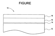
遮熱コーティングの種々の実施形態をさらに図面を参照して以下に説明する。図1に物品10の金属基材に使用する遮熱コーティングの一実施形態の側断面図を示す。物品10は金属基材12を有する。基材12は、種々の金属、具体的には通例遮熱コーティングで保護される金属合金、例えばニッケル、コバルト及び/又は鉄合金を主成分とする金属合金のいずれでもよい。例えば、基材12は高温、耐熱合金、例えば超合金にすることができる。このような耐熱性合金は、種々の文献、例えばRossらの米国特許第5399313号(1995年3月21日発行)及びGellらの米国特許第4116723号(1978年9月26日発行)に開示されている。耐熱性合金の概要は、Kirk-Othmer's Encyclopedia of Chemical Technology, 3rd Ed., Vol. 12, pp. 417-479 (1980)及びVol. 15, pp. 787-800 (1981)に記載されている。耐熱性ニッケル基合金の具体例には商品名Inconel(登録商標)、Nimonic(登録商標)、Rene(登録商標)(例えば、Rene80合金、Rene95合金)及びUdimet(登録商標)がある。上記のように、基材12は様々な種類があるが、代表的にはタービン部品、例えば翼形部(具体的には、ブレード)又はタービンシュラウドなどの形態である。
Various embodiments of the thermal barrier coating are further described below with reference to the drawings. FIG. 1 shows a side cross-sectional view of one embodiment of a thermal barrier coating used on the metal substrate of the
図1に示すように、物品10は、所望に応じて、基材12の上側に隣接するボンドコート層14も有する。ボンドコート層14は、典型的に耐酸化金属材料から形成され、下側の基材12を保護し、遮熱コーティング16が基材12に一層強く密着できるようにする。ボンドコート層14に適当な材料には、MCrAlY合金粉末(Mは、鉄、ニッケル、白金、コバルトなどの金属である)、特にニッケルアルミナイド、白金アルミナイドなどの種々の金属アルミナイドがある。このボンドコート層14は、基材12上に物理蒸着(PVD)、例えば電子ビーム物理蒸着(EBPVD)、プラズマ溶射、例えば大気プラズマ溶射(APS)及び真空プラズマ溶射(VPS)、又は他の溶射堆積法、例えば高速フレーム溶射(HVOF)溶射、爆発溶射及びワイヤー溶射、化学蒸着(CVD)又はこれらの方法の組合せ、例えば、プラズマ溶射とCVD法の組合せのいずれかにより、設層、堆積、形成することができる。典型的には、遮熱コーティング16に使用するようなプラズマ溶射法を用いてボンドコート層14を堆積することができる。通常、堆積ボンドコート層14の厚さは約1〜約19.5ミル(約25〜約495μm)の範囲である。EBPVDなどのPVD法で堆積したボンドコート層14の厚さは、より典型的には約1〜約3ミル(約25〜約76μm)の範囲である。APSなどのプラズマ溶射法で堆積したボンドコート層の厚さは、より典型的には約3〜約15ミル(約76〜約381μm)の範囲である。
As shown in FIG. 1, the
TBC16はボンドコート層14の上側に隣接する。TBC16の厚さは、通常約1〜約100ミル(約25〜約2540μm)であり、種々の要因、例えば物品10に依存する。例えば、タービンシュラウドの場合、TBC16は、典型的には厚めであり、通常約30〜約70ミル、より典型的には約40〜約60ミルの範囲である。対照的に、タービンブレードの場合、TBC16は、典型的には薄めであり、通常約1〜約30ミル、より典型的には約3〜約20ミルの範囲である。
The
TBC16は、さらにTBCの上側に隣接する外層18を含む。外層18は、約60%以上、かつ露出表面に堆積する環境汚染物に対してTBC16を少なくとも部分的に保護するのに十分な量のアルミナを含有する溶射アルミナ系皮膜である。別の実施形態では、アルミナ系皮膜は約87重量%以上のアルミナを含有する。
The
TBC16の外層18に存在するアルミナは、物品10の露出表面に堆積するCMASの悪影響に対する保護又は抑制を実現する。アルミナ系皮膜18は、タービン運転時の高温、例えば2000°F超の温度で、酸化物の堆積物が溶融しないようにCMAS汚染物質の融点を上昇させるか、簡単に流れないように溶融堆積物の粘度を上げる。その結果、このようなCMAS堆積物は、TBC16の通常の多孔質構造に浸透したり、多孔質構造を溶解することができなくなる。
The alumina present in the
アルミナ系外層18の厚さは、特に限定されないが、一般にTBC16全体の所望の厚さ、特定の物品10などの種々の要因に依存する。通常、外層18は0.5ミル〜4ミルである。アルミナ系層の断熱効果はTBCよりはるかに少ないので、TBCの効果を出来るだけ大きくするように、外層18の厚さを薄くすることが望ましい。
The thickness of the alumina-based
ボンドコート層14及びTBC16の外層18の組成及び厚さは、通常適切なCTEを与えるように調整して種々の層と基材12の間の熱応力を出来るだけ小さくし、種々の層が互いに又は基材12から離れないようにする。通常、各層のCTEは、典型的に外層18からボンドコート層14に向かって増加する。
The composition and thickness of the
本発明のTBC形成では、当業者に周知の種々の溶射法を用いて遮熱コーティング材料を堆積(成膜)することができる。例えばKirk-Othmer Encyclopedia of Chemical Technology, 3rd Ed., Vol. 15, p.255及びその引用文献、並びに川崎らの米国特許第5332598号(1994年7月26日発行)、Savkarらの米国特許第5047612号(1991年9月10日発行)、及び伊藤らの米国特許第4741286号(1998年5月3日発行)参照。これらは、本発明で使用するのに適当なプラズマ溶射の様々な側面に関して有用な情報を与える。一般に、典型的なプラズマ溶射法では、まず高温プラズマを形成して熱プルームを発生する。遮熱コーティング材料、例えばアルミナ系粉末をプルームに供給し、高速プルームをTBC16の表面に差し向ける。このようなプラズマ溶射被覆法の詳細、例えば種々の関連工程及びプラズマ溶射パラメータのようなプロセスパラメータは当業者に周知である。プラズマ溶射パラメータには、具体的に溶射距離(ガン−基材)、スプレーの通過回数、粉末供給速度、粒子速度、トーチ電力の選択、プラズマガスの選択、化学量論的な酸化物にする酸化制御、堆積角度、堆積皮膜の後処理などがある。トーチ電力は、約10kW〜約200kWの範囲、好ましい実施形態では約40kW〜約60kWの範囲で変化する。プラズマプルーム(即ち、プラズマジェット)中に流れ込むアルミナ系皮膜材料粒子の速度も、通常厳密に制御するパラメータである。
In the TBC formation of the present invention, the thermal barrier coating material can be deposited (film formation) using various thermal spraying methods well known to those skilled in the art. For example, Kirk-Othmer Encyclopedia of Chemical Technology, 3rd Ed., Vol. 15, p.255 and references cited therein, as well as U.S. Pat. No. 5,332,598 issued Kawasaki et al. See US Pat. No. 5,047,612 (issued on Sep. 10, 1991) and U.S. Pat. No. 4,712,286 issued on May 3, 1998 to Ito et al. These provide useful information regarding various aspects of plasma spraying suitable for use in the present invention. In general, in a typical plasma spray process, a high temperature plasma is first generated to generate a thermal plume. A thermal barrier coating material, such as alumina-based powder, is supplied to the plume and a high speed plume is directed to the surface of the
簡潔に述べると、典型的なプラズマ溶射システムは、被覆される基材の堆積用表面の方向に向けられたノズルを有するプラズマガンアノードを備える。プラズマガンは、多くの場合、例えばガンを基材表面に対して様々なパターンで移動することができるロボット機構により自動的に制御される。プラズマプルームはプラズマガンアノードの出口と基材表面間で軸線方向に延びる。適当な粉末注入手段をアノードと基材表面間の望ましい所定の軸線方向位置に配置する。このようなシステムの実施形態では、粉末注入手段はプラズマプルーム領域から半径方向に離れており、粉末材料の注入管は、粉末をプラズマプルーム中に所望の角度で送ることができる適当な位置に設けられる。粉末粒子をキャリアガス中にのせて、注入器からプラズマプルーム中に推進する。その後、粒子をプラズマ中で加熱し、基材に向かって推進する。粒子は溶融し、基材に衝突し、急速に冷えて、遮熱コーティングを形成する。 Briefly stated, a typical plasma spray system includes a plasma gun anode having a nozzle oriented in the direction of the deposition surface of the substrate to be coated. The plasma gun is often automatically controlled, for example, by a robotic mechanism that can move the gun in various patterns relative to the substrate surface. The plasma plume extends axially between the plasma gun anode outlet and the substrate surface. Appropriate powder injection means are disposed at a desired predetermined axial position between the anode and the substrate surface. In such a system embodiment, the powder injection means is radially away from the plasma plume region, and the powder material injection tube is provided at a suitable location where the powder can be fed into the plasma plume at the desired angle. It is done. Powder particles are placed in a carrier gas and propelled from the injector into the plasma plume. The particles are then heated in plasma and propelled towards the substrate. The particles melt, impinge on the substrate, and cool rapidly to form a thermal barrier coating.
TBC上に緻密で、平滑な単層の薄いアルミナ系皮膜を堆積するのに適当な溶射法は、高速酸素フレーム(HVOF)又は高速大気プラズマ溶射(HV−APS)である。この実施形態の利点として、単一の皮膜でTBCにCMAS抑制と耐汚損性の両方を与えることができる。CMAS抑制皮膜をタービン部品上に設けることは約2200°F(1204℃)超でのガスタービン運転に望ましい。CMAS抑制皮膜なしの場合、TBCが損傷を受け、部品が予定された次回の使用の前に破損する恐れがある。耐汚損皮膜はデザイン通りの性能が継続するのを確実にするために必要である。タービンの高温ガス流路部品が汚損を受けると、空気力学的特性が変化し、効率や出力が下がる。皮膜の表面粗さが小さいと、汚損、即ちCMASなどの汚染物の表面上への付着が低減する。 A suitable thermal spray method for depositing a dense, smooth, single-layer, thin alumina-based coating on the TBC is a high velocity oxygen flame (HVOF) or a high velocity atmospheric plasma spray (HV-APS). As an advantage of this embodiment, a single coating can impart both CMAS suppression and fouling resistance to the TBC. Providing a CMAS suppression coating on the turbine component is desirable for gas turbine operation above about 2200 ° F. (1204 ° C.). Without the CMAS suppression coating, the TBC may be damaged and the part may break before the next scheduled use. The antifouling coating is necessary to ensure that the designed performance continues. As turbine hot gas flow path components are fouled, the aerodynamic characteristics change, reducing efficiency and power output. When the surface roughness of the film is small, fouling, that is, adhesion of contaminants such as CMAS on the surface is reduced.
1例として、HVOFを使用して、TBC上にアルミナ系皮膜を堆積することができる。それぞれの熱源は、フレーム及び熱プルームであり、入力ガス、燃料及びノズルのデザインにより制御される。酸素及び燃料を高圧で供給すれば、ノズルからフレームが超音速で出てくる。収束・発散ノズルを有する特定のガン、具体的にはMETCO DJ2600を使用して、アルミナ系皮膜を設けることができる。しかし、TopGunやJetKoteなどのストレートボアHVOFガンを用いることもできる。これらのプロセスパラメーターを調節する方法は当業者に明らかである。この実施形態の利点は、皮膜を大気条件で堆積でき、真空や防爆環境を必要としないことである。さらに、硬化や追加の処理工程も必要ない。 As an example, an HVOF can be used to deposit an alumina-based coating on the TBC. Each heat source is a frame and a heat plume and is controlled by the input gas, fuel and nozzle design. If oxygen and fuel are supplied at high pressure, the frame comes out of the nozzle at supersonic speed. A specific gun having a converging / diverging nozzle, specifically METCO DJ2600, can be used to provide an alumina-based coating. However, straight bore HVOF guns such as TopGun and JetKote can also be used. It will be clear to those skilled in the art how to adjust these process parameters. The advantage of this embodiment is that the coating can be deposited at atmospheric conditions and does not require a vacuum or explosion-proof environment. Furthermore, no curing or additional processing steps are necessary.
CMAS抑制については、遮熱コーティングの外表面上に堆積したアルミナ系皮膜は、遮熱コーティングの表面温度でCMAS汚染物質と反応することによって犠牲作用をなす。理論に束縛されるものではないが、この反応は、犠牲皮膜が少なくとも部分的に消費される化学反応であり、汚染物質の溶融温度又は粘度を上昇させる。具体的には、CMAS汚染物質の溶融温度を、CMASと犠牲アルミナ系皮膜の間の反応領域で少なくともTBCの表面温度まで上昇させることができる。このような融点の上昇は、CMAS材料を十分に粘稠にし、遮熱コーティングへの浸透又は遮熱コーティングとの反応を起こりにくくするか、表面にごく近いところに限定し、かくしてTBCのクラック及び/又は剥落を回避し、下側加工品に対するTBCの熱保護が失われるのを防止する。具体的には、形成されるほぼすべての液体汚染物の溶融温度又は粘度を効果的に上昇させるのに十分な量で、犠牲アルミナ系皮膜を遮熱コーティングに設ける。遮熱コーティングの表面上のアルミナ系皮膜は1μm以下の厚さで、遮熱コーティング中へ溶融汚染物質が浸透するのを防止するのに有用である。溶融温度を上昇させるのに十分な犠牲材料が得られる。 For CMAS suppression, the alumina-based coating deposited on the outer surface of the thermal barrier coating sacrifices by reacting with CMAS contaminants at the surface temperature of the thermal barrier coating. Without being bound by theory, this reaction is a chemical reaction in which the sacrificial coating is at least partially consumed, increasing the melting temperature or viscosity of the contaminant. Specifically, the melting temperature of the CMAS contaminant can be raised to at least the surface temperature of TBC in the reaction region between the CMAS and the sacrificial alumina-based coating. Such an increase in melting point renders the CMAS material sufficiently viscous and less likely to penetrate or react with the thermal barrier coating or to be very close to the surface, thus cracking TBC and / Or avoid flaking and prevent loss of thermal protection of the TBC for the lower workpiece. Specifically, the sacrificial alumina-based coating is provided on the thermal barrier coating in an amount sufficient to effectively increase the melting temperature or viscosity of nearly all liquid contaminants formed. The alumina-based coating on the surface of the thermal barrier coating is 1 μm or less in thickness and is useful for preventing molten contaminants from penetrating into the thermal barrier coating. Sacrificial material sufficient to increase the melting temperature is obtained.
耐汚損については、この実施形態は皮膜の後処理なしで汚損を低減できる。汚損は粗い表面上では速くなる傾向があるので、高速溶射による平滑な表面は汚損を低減するはすである。表面は平均表面粗さが約4μm未満〜約0.75μmと平滑であるので、大抵の用途で再仕上げ及び平滑化処理は必要ない。さらに、TBC上への皮膜の接着は十分に強いので、炉での硬化も接着性向上処理も必要でない。一般に皮膜の後処理は必要ないが、本発明の方法から皮膜の後処理を除外するべきではない。 For antifouling, this embodiment can reduce fouling without post-treatment of the coating. Since fouling tends to be faster on rough surfaces, a smooth surface by high speed thermal spraying should reduce fouling. Since the surface is smooth with an average surface roughness of less than about 4 μm to about 0.75 μm, refinishing and smoothing is not required for most applications. Furthermore, the adhesion of the film on the TBC is sufficiently strong so that neither curing in the furnace nor treatment for improving adhesion is required. In general, no post-treatment of the coating is necessary, but post-treatment of the coating should not be excluded from the method of the present invention.
本実施形態の別の利点は、基材の寸法制限や面積制限がなく、大型の部品に適していることである。HVOFやHV−APSなどの溶射法を使用すると、皮膜を所望の厚さに選択的に設けることができ、皮膜の後処理も不要である。マスキングなしで選択的な設層ができる。皮膜は、厚さに制限はなく、長期間に渡って保護を提供することができる。 Another advantage of this embodiment is that it is suitable for large-sized parts without any dimensional or area restrictions on the substrate. When a thermal spraying method such as HVOF or HV-APS is used, the coating can be selectively provided at a desired thickness, and no post-treatment of the coating is necessary. Selective layering is possible without masking. The coating is not limited in thickness and can provide protection over a long period of time.
別の利点として、保管期限があったり、コストを上げたり、より複雑な製造工程を必要としたりする揮発性又は爆発性の有機溶媒を使用しない。さらに、乾燥や炉での硬化などの皮膜の後処理を必要としない。 Another advantage is that it does not use volatile or explosive organic solvents that have a shelf life, increase costs, or require more complex manufacturing processes. Furthermore, no post-treatment of the coating such as drying or curing in the furnace is required.
実施形態の他の利点はコストの低減である。1回の被覆プロセスは他の方法より迅速で安価である。その上、マスキング及び有機溶媒が必要ないことで、さらにコストが低減する。真空又は防爆環境も必要ない。 Another advantage of the embodiment is cost reduction. A single coating process is faster and cheaper than other methods. Moreover, the need for masking and organic solvents is eliminated, further reducing costs. No vacuum or explosion-proof environment is required.
特別に定義されない限り、本明細書で用いられる科学技術用語は、当業者が一般に理解するのと同様な意味を有する。単数表現は、数量を限定するものではなく、記載要素が存在することを表す。数量にともなう修飾語「約」は、表示値を含み、文脈で示された意味を持つ(例えば特定の数量の測定にともなう誤差を含む)。本明細書で用いたすべての量、部、比率及び%は、特記しない限り重量による。 Unless defined otherwise, scientific and technical terms used herein have the same meaning as commonly understood by one of ordinary skill in the art. The singular expression does not limit the quantity but indicates the presence of a description element. The modifier “about” with quantity includes the indicated value and has the meaning indicated in the context (eg, includes the error associated with the measurement of a particular quantity). All amounts, parts, ratios and percentages used herein are by weight unless otherwise specified.
本明細書全体を通して言及した「一実施形態」、「別の実施形態」、「他の実施形態」などは、その実施形態に記載された特定要素(例えば、特徴、構造及び/又は特性)が、本明細書の少なくとも1つの実施形態に含まれ、別の実施形態には存在してもしなくてもよいことを意味する。さらに、記載された要素を任意適当な方法で種々の実施形態に取り入れてもよい。 “One embodiment”, “another embodiment”, “another embodiment”, etc. referred to throughout this specification refer to specific elements (eg, features, structures and / or characteristics) described in that embodiment. , Is included in at least one embodiment of the specification, and may or may not be present in another embodiment. Moreover, the described elements may be incorporated into various embodiments in any suitable manner.
本明細書では、具体例を挙げて、最良の形態を含む本発明を開示するとともに、当業者が本発明を実施できるようにしている。本発明の要旨は、特許請求の範囲に規定された通りで、当業者が想起できる他の例を含むことができる。このような他の例は、特許請求の範囲の文言と異ならない構造要素を有するか、特許請求の範囲の文言と実質的に異ならない均等な構造要素を含むならば、特許請求の範囲に含まれる。 In the present specification, the present invention including the best mode is disclosed with specific examples, and those skilled in the art can implement the present invention. The gist of the present invention is as defined in the claims and may include other examples that occur to those skilled in the art. Such other examples are included in the scope of claims if they have structural elements that do not differ from the language of the claims, or include equivalent structural elements that do not substantially differ from the language of the claims. It is.
10 物品
11 基材
14 ボンドコート
16 遮熱コーティング
18 アルミナ系皮膜
10 Article 11
Claims (13)
遮熱コーティングを設けた物品を用意する工程と、
アルミナ系皮膜の総重量に基づいて、60重量%以上のアルミナと、残部のチタニア、ジルコニア及びガドリニアとからなる組成を有するアルミナ粉末を加熱する工程と、
前記アルミナ粉末を前記遮熱コーティング上に溶射して平均表面粗さが0.75μm以上4.0μm未満のアルミナ系皮膜を形成する工程と
を含み、
前記アルミナ系皮膜が、カルシウム−マグネシウム−アルミニウム−ケイ素混合酸化物を含有する汚染物質の融点をアルミナ系皮膜が存在しない汚染物質に比べて上昇させる、
遮熱コーティングへのアルミナ系皮膜の堆積方法。 A method of depositing an alumina-based film on a thermal barrier coating,
Preparing an article provided with a thermal barrier coating;
Based on the total weight of the alumina-based coating, and heating the alumina powder having a 60% or more by weight of alumina, the remainder of the titania, the composition comprising a zirconia and gadolinia,
It includes <br/> the step of average surface roughness by spraying onto the thermal barrier coating the alumina powder to form an alumina-based coating of less than 0.75 .mu.m 4.0 .mu.m,
The alumina-based coating raises the melting point of a contaminant containing a calcium-magnesium-aluminum-silicon mixed oxide compared to a contaminant without an alumina-based coating;
A method for depositing an alumina-based film on a thermal barrier coating.
前記遮熱コーティング上に設けられた溶射アルミナ系皮膜であって、前記アルミナ系皮膜がその総重量に基づいて60重量%以上のアルミナと、残部のチタニア、ジルコニア及びガドリニアとからなり、カルシウム−マグネシウム−アルミニウム−ケイ素混合酸化物系を含有する汚染物質の融点を上昇させるのに有効な0.5〜4ミル(13〜102μm)の厚みを有しており、溶射アルミナ系皮膜の平均表面粗さが0.75μm以上4.0μm未満である、溶射アルミナ系皮膜と
を含む皮膜系。 A thermal barrier coating containing a chemically stabilized zirconia material provided on the metal part;
A spray-sprayed alumina-based coating provided on the thermal barrier coating , the alumina-based coating comprising 60 % by weight or more of alumina based on the total weight thereof and the balance of titania, zirconia and gadolinia, and calcium-magnesium An average surface roughness of a sprayed alumina coating having a thickness of 0.5-4 mils (13-102 μm) effective to increase the melting point of contaminants containing an aluminum-silicon mixed oxide system; A sprayed alumina-based coating having a thickness of 0.75 μm or more and less than 4.0 μm ;
A coating system containing
13. A coating system according to any one of claims 9 to 12 , wherein the metal part contains a nickel-base alloy, a cobalt-base alloy, an iron-base alloy, and combinations thereof.
Applications Claiming Priority (2)
| Application Number | Priority Date | Filing Date | Title |
|---|---|---|---|
| US11/923,011 | 2007-10-24 | ||
| US11/923,011 US7833586B2 (en) | 2007-10-24 | 2007-10-24 | Alumina-based protective coatings for thermal barrier coatings |
Publications (3)
| Publication Number | Publication Date |
|---|---|
| JP2009108410A JP2009108410A (en) | 2009-05-21 |
| JP2009108410A5 JP2009108410A5 (en) | 2011-11-24 |
| JP5554488B2 true JP5554488B2 (en) | 2014-07-23 |
Family
ID=40239723
Family Applications (1)
| Application Number | Title | Priority Date | Filing Date |
|---|---|---|---|
| JP2008270423A Active JP5554488B2 (en) | 2007-10-24 | 2008-10-21 | Alumina-based protective coating for thermal barrier coating |
Country Status (3)
| Country | Link |
|---|---|
| US (1) | US7833586B2 (en) |
| EP (1) | EP2053141B1 (en) |
| JP (1) | JP5554488B2 (en) |
Cited By (2)
| Publication number | Priority date | Publication date | Assignee | Title |
|---|---|---|---|---|
| US10808308B2 (en) | 2016-06-08 | 2020-10-20 | Mitsubishi Heavy Industries, Ltd. | Thermal barrier coating, turbine member, and gas turbine |
| US11946147B2 (en) | 2018-03-26 | 2024-04-02 | Mitsubishi Heavy Industries, Ltd. | Thermal barrier coating, turbine member, gas turbine, and method for producing thermal barrier coating |
Families Citing this family (27)
| Publication number | Priority date | Publication date | Assignee | Title |
|---|---|---|---|---|
| EP2233450A1 (en) * | 2009-03-27 | 2010-09-29 | Alstom Technology Ltd | Multilayer thermal protection system and its use |
| US20110151219A1 (en) * | 2009-12-21 | 2011-06-23 | Bangalore Nagaraj | Coating Systems for Protection of Substrates Exposed to Hot and Harsh Environments and Coated Articles |
| JP5622399B2 (en) * | 2010-01-07 | 2014-11-12 | 三菱重工業株式会社 | Thermal barrier coating, turbine member equipped with the same, and gas turbine |
| US20110217568A1 (en) * | 2010-03-05 | 2011-09-08 | Vinod Kumar Pareek | Layered article |
| US20110223317A1 (en) * | 2010-03-12 | 2011-09-15 | United Technologies Corporation | Direct thermal stabilization for coating application |
| JP5561733B2 (en) | 2010-12-28 | 2014-07-30 | 株式会社日立製作所 | Gas turbine component having thermal barrier coating and gas turbine using the same |
| US9139897B2 (en) | 2010-12-30 | 2015-09-22 | United Technologies Corporation | Thermal barrier coatings and methods of application |
| WO2012119016A2 (en) | 2011-03-02 | 2012-09-07 | Applied Thin Films, Inc. | Protective internal coatings for porous substrates |
| US20130082446A1 (en) * | 2011-09-30 | 2013-04-04 | General Electric Company | Method of repairing rotating machine components |
| FR2994397B1 (en) * | 2012-08-07 | 2014-08-01 | Snecma | COATING IN ABRADABLE MATERIAL WITH LOW SURFACE ROUGHNESS |
| US11047033B2 (en) | 2012-09-05 | 2021-06-29 | Raytheon Technologies Corporation | Thermal barrier coating for gas turbine engine components |
| US20140174091A1 (en) * | 2012-12-21 | 2014-06-26 | United Technologies Corporation | Repair procedure for a gas turbine engine via variable polarity welding |
| DE102013213742A1 (en) | 2013-07-12 | 2015-01-15 | MTU Aero Engines AG | CMAS-INERTE HEAT INSULATION LAYER AND METHOD FOR THE PRODUCTION THEREOF |
| DE102013217627A1 (en) | 2013-09-04 | 2015-03-05 | MTU Aero Engines AG | Thermal insulation layer system with corrosion and erosion protection |
| US20150308275A1 (en) * | 2014-04-29 | 2015-10-29 | General Electric Company | Coating method and coated article |
| CN106191752A (en) * | 2015-03-10 | 2016-12-07 | 中国农业机械化科学研究院 | A kind of thermal barrier coating melt surface deposit protective coating and preparation method thereof |
| CN104862687B (en) * | 2015-04-29 | 2017-06-13 | 哈尔滨工业大学 | A kind of preparation method of metal thermal protection struc ture face coat |
| US11952828B1 (en) * | 2015-08-13 | 2024-04-09 | National Technology & Engineering Solutions Of Sandia, Llc | Thermal barrier systems and methods for access delay |
| DE102016201947A1 (en) | 2016-02-10 | 2017-08-10 | MTU Aero Engines AG | Thermal barrier coating with high corrosion resistance |
| WO2018013757A2 (en) | 2016-07-14 | 2018-01-18 | Corning Incorporated | Methods of reducing surface roughness of reflectance coatings for duv mirrors |
| EP3768874A4 (en) | 2018-03-19 | 2022-03-30 | Applied Materials, Inc. | Methods for depositing coatings on aerospace components |
| JP7045236B2 (en) * | 2018-03-27 | 2022-03-31 | 三菱重工業株式会社 | Thermal barrier coatings, turbine components and gas turbines |
| WO2020219332A1 (en) | 2019-04-26 | 2020-10-29 | Applied Materials, Inc. | Methods of protecting aerospace components against corrosion and oxidation |
| US20220081763A1 (en) * | 2020-09-17 | 2022-03-17 | Applied Materials, Inc. | Aluminum oxide protective coatings on turbocharger components and other rotary equipment components |
| CN112553565B (en) * | 2020-11-13 | 2023-04-21 | 厦门金鹭特种合金有限公司 | Interlayer for sintering hard alloy pressed product |
| CN112962050A (en) * | 2021-03-07 | 2021-06-15 | 湖南大学 | Method for improving high temperature resistance and corrosion resistance of thermal barrier coating |
| CN113862599B (en) * | 2021-09-09 | 2023-01-31 | 中国科学院上海硅酸盐研究所 | Al 2 O 3 -GdAlO 3 Amorphous oxide ceramic coating and method for preparing same |
Family Cites Families (18)
| Publication number | Priority date | Publication date | Assignee | Title |
|---|---|---|---|---|
| US4116723A (en) | 1976-11-17 | 1978-09-26 | United Technologies Corporation | Heat treated superalloy single crystal article and process |
| US5399313A (en) | 1981-10-02 | 1995-03-21 | General Electric Company | Nickel-based superalloys for producing single crystal articles having improved tolerance to low angle grain boundaries |
| JPS61259777A (en) | 1985-05-13 | 1986-11-18 | Onoda Cement Co Ltd | Single-torch type plasma spraying method and apparatus |
| US4999225A (en) | 1989-01-05 | 1991-03-12 | The Perkin-Elmer Corporation | High velocity powder thermal spray method for spraying non-meltable materials |
| US5059095A (en) | 1989-10-30 | 1991-10-22 | The Perkin-Elmer Corporation | Turbine rotor blade tip coated with alumina-zirconia ceramic |
| US5047612A (en) | 1990-02-05 | 1991-09-10 | General Electric Company | Apparatus and method for controlling powder deposition in a plasma spray process |
| JPH0693404A (en) | 1991-12-04 | 1994-04-05 | Ngk Insulators Ltd | Production of lanthanum chromite film and lanthanum chromite coating |
| US5660885A (en) | 1995-04-03 | 1997-08-26 | General Electric Company | Protection of thermal barrier coating by a sacrificial surface coating |
| US6465090B1 (en) | 1995-11-30 | 2002-10-15 | General Electric Company | Protective coating for thermal barrier coatings and coating method therefor |
| US6485792B1 (en) | 1999-08-27 | 2002-11-26 | General Electric Company | Endurance of NiA1 coatings by controlling thermal spray processing variables |
| US6627323B2 (en) | 2002-02-19 | 2003-09-30 | General Electric Company | Thermal barrier coating resistant to deposits and coating method therefor |
| US6933066B2 (en) | 2002-12-12 | 2005-08-23 | General Electric Company | Thermal barrier coating protected by tantalum oxide and method for preparing same |
| US6893750B2 (en) | 2002-12-12 | 2005-05-17 | General Electric Company | Thermal barrier coating protected by alumina and method for preparing same |
| US6933061B2 (en) | 2002-12-12 | 2005-08-23 | General Electric Company | Thermal barrier coating protected by thermally glazed layer and method for preparing same |
| US20050282032A1 (en) * | 2004-06-18 | 2005-12-22 | General Electric Company | Smooth outer coating for combustor components and coating method therefor |
| US7368164B2 (en) | 2004-06-18 | 2008-05-06 | General Electric Company | Smooth outer coating for combustor components and coating method therefor |
| US20060115661A1 (en) | 2004-12-01 | 2006-06-01 | General Electric Company | Protection of thermal barrier coating by a sacrificial coating |
| US7374825B2 (en) | 2004-12-01 | 2008-05-20 | General Electric Company | Protection of thermal barrier coating by an impermeable barrier coating |
-
2007
- 2007-10-24 US US11/923,011 patent/US7833586B2/en active Active
-
2008
- 2008-10-16 EP EP08166731.3A patent/EP2053141B1/en active Active
- 2008-10-21 JP JP2008270423A patent/JP5554488B2/en active Active
Cited By (2)
| Publication number | Priority date | Publication date | Assignee | Title |
|---|---|---|---|---|
| US10808308B2 (en) | 2016-06-08 | 2020-10-20 | Mitsubishi Heavy Industries, Ltd. | Thermal barrier coating, turbine member, and gas turbine |
| US11946147B2 (en) | 2018-03-26 | 2024-04-02 | Mitsubishi Heavy Industries, Ltd. | Thermal barrier coating, turbine member, gas turbine, and method for producing thermal barrier coating |
Also Published As
| Publication number | Publication date |
|---|---|
| JP2009108410A (en) | 2009-05-21 |
| EP2053141B1 (en) | 2020-12-16 |
| US7833586B2 (en) | 2010-11-16 |
| EP2053141A1 (en) | 2009-04-29 |
| US20090110903A1 (en) | 2009-04-30 |
Similar Documents
| Publication | Publication Date | Title |
|---|---|---|
| JP5554488B2 (en) | Alumina-based protective coating for thermal barrier coating | |
| EP1428908B1 (en) | Thermal barrier coating protected by thermally glazed layer and method for preparing same | |
| US6893750B2 (en) | Thermal barrier coating protected by alumina and method for preparing same | |
| US7226668B2 (en) | Thermal barrier coating containing reactive protective materials and method for preparing same | |
| EP1428902B1 (en) | Thermal barrier coating protected by infiltrated alumina and method for preparing same | |
| US7351482B2 (en) | Ceramic compositions for thermal barrier coatings stabilized in the cubic crystalline phase | |
| US6887595B1 (en) | Thermal barrier coatings having lower layer for improved adherence to bond coat | |
| US6933066B2 (en) | Thermal barrier coating protected by tantalum oxide and method for preparing same | |
| EP1908856B2 (en) | Segmented abradable coatings and process(es) for applying the same | |
| US7364802B2 (en) | Ceramic compositions useful in thermal barrier coatings having reduced thermal conductivity | |
| EP1588992A1 (en) | Mixed metal oxide ceramic compositions for reduced conductivity thermal barrier coatings | |
| JP2007231422A (en) | Coating process and coated article | |
| US20110048017A1 (en) | Method of depositing protective coatings on turbine combustion components | |
| EP3438325A1 (en) | Improved adhesion of thermal spray coatings over a smooth surface | |
| WO2012029540A1 (en) | Heat-masking coating film, process for production thereof, and heat-resistant alloy members using the same | |
| EP2423347A1 (en) | Method for forming a thermal barrier coating and a turbine component with the thermal barrier coating | |
| EP3839088B1 (en) | Methods for manufacturing porous barrier coatings using air plasma spray techniques |
Legal Events
| Date | Code | Title | Description |
|---|---|---|---|
| RD04 | Notification of resignation of power of attorney |
Free format text: JAPANESE INTERMEDIATE CODE: A7424 Effective date: 20110214 |
|
| A521 | Request for written amendment filed |
Free format text: JAPANESE INTERMEDIATE CODE: A523 Effective date: 20111011 |
|
| A621 | Written request for application examination |
Free format text: JAPANESE INTERMEDIATE CODE: A621 Effective date: 20111011 |
|
| A521 | Request for written amendment filed |
Free format text: JAPANESE INTERMEDIATE CODE: A523 Effective date: 20121005 |
|
| A977 | Report on retrieval |
Free format text: JAPANESE INTERMEDIATE CODE: A971007 Effective date: 20130411 |
|
| A131 | Notification of reasons for refusal |
Free format text: JAPANESE INTERMEDIATE CODE: A131 Effective date: 20130416 |
|
| A601 | Written request for extension of time |
Free format text: JAPANESE INTERMEDIATE CODE: A601 Effective date: 20130712 |
|
| A602 | Written permission of extension of time |
Free format text: JAPANESE INTERMEDIATE CODE: A602 Effective date: 20130718 |
|
| A601 | Written request for extension of time |
Free format text: JAPANESE INTERMEDIATE CODE: A601 Effective date: 20130816 |
|
| A602 | Written permission of extension of time |
Free format text: JAPANESE INTERMEDIATE CODE: A602 Effective date: 20130821 |
|
| A601 | Written request for extension of time |
Free format text: JAPANESE INTERMEDIATE CODE: A601 Effective date: 20130913 |
|
| A602 | Written permission of extension of time |
Free format text: JAPANESE INTERMEDIATE CODE: A602 Effective date: 20130919 |
|
| A521 | Request for written amendment filed |
Free format text: JAPANESE INTERMEDIATE CODE: A523 Effective date: 20131015 |
|
| TRDD | Decision of grant or rejection written | ||
| A01 | Written decision to grant a patent or to grant a registration (utility model) |
Free format text: JAPANESE INTERMEDIATE CODE: A01 Effective date: 20140430 |
|
| A61 | First payment of annual fees (during grant procedure) |
Free format text: JAPANESE INTERMEDIATE CODE: A61 Effective date: 20140529 |
|
| R150 | Certificate of patent or registration of utility model |
Ref document number: 5554488 Country of ref document: JP Free format text: JAPANESE INTERMEDIATE CODE: R150 |
|
| R250 | Receipt of annual fees |
Free format text: JAPANESE INTERMEDIATE CODE: R250 |
|
| R250 | Receipt of annual fees |
Free format text: JAPANESE INTERMEDIATE CODE: R250 |
|
| R250 | Receipt of annual fees |
Free format text: JAPANESE INTERMEDIATE CODE: R250 |
|
| R250 | Receipt of annual fees |
Free format text: JAPANESE INTERMEDIATE CODE: R250 |
|
| R250 | Receipt of annual fees |
Free format text: JAPANESE INTERMEDIATE CODE: R250 |
|
| R250 | Receipt of annual fees |
Free format text: JAPANESE INTERMEDIATE CODE: R250 |
|
| R250 | Receipt of annual fees |
Free format text: JAPANESE INTERMEDIATE CODE: R250 |
|
| S111 | Request for change of ownership or part of ownership |
Free format text: JAPANESE INTERMEDIATE CODE: R313113 |
|
| R350 | Written notification of registration of transfer |
Free format text: JAPANESE INTERMEDIATE CODE: R350 |