EP2113441A2 - Elektrische Lenksäulenklemmeinrichtung mit Aktuatorbewegung in eine Richtung - Google Patents
Elektrische Lenksäulenklemmeinrichtung mit Aktuatorbewegung in eine Richtung Download PDFInfo
- Publication number
- EP2113441A2 EP2113441A2 EP09158470A EP09158470A EP2113441A2 EP 2113441 A2 EP2113441 A2 EP 2113441A2 EP 09158470 A EP09158470 A EP 09158470A EP 09158470 A EP09158470 A EP 09158470A EP 2113441 A2 EP2113441 A2 EP 2113441A2
- Authority
- EP
- European Patent Office
- Prior art keywords
- locking mechanism
- pivot
- telescope
- column jacket
- assembly
- Prior art date
- Legal status (The legal status is an assumption and is not a legal conclusion. Google has not performed a legal analysis and makes no representation as to the accuracy of the status listed.)
- Granted
Links
- 230000007246 mechanism Effects 0.000 claims abstract description 69
- 230000006835 compression Effects 0.000 claims description 8
- 238000007906 compression Methods 0.000 claims description 8
- 230000004044 response Effects 0.000 claims description 5
- 230000004913 activation Effects 0.000 description 1
- 230000005611 electricity Effects 0.000 description 1
- 238000004519 manufacturing process Methods 0.000 description 1
- 230000004048 modification Effects 0.000 description 1
- 238000012986 modification Methods 0.000 description 1
Images


Classifications
-
- B—PERFORMING OPERATIONS; TRANSPORTING
- B62—LAND VEHICLES FOR TRAVELLING OTHERWISE THAN ON RAILS
- B62D—MOTOR VEHICLES; TRAILERS
- B62D1/00—Steering controls, i.e. means for initiating a change of direction of the vehicle
- B62D1/02—Steering controls, i.e. means for initiating a change of direction of the vehicle vehicle-mounted
- B62D1/16—Steering columns
- B62D1/18—Steering columns yieldable or adjustable, e.g. tiltable
- B62D1/184—Mechanisms for locking columns at selected positions
-
- B—PERFORMING OPERATIONS; TRANSPORTING
- B62—LAND VEHICLES FOR TRAVELLING OTHERWISE THAN ON RAILS
- B62D—MOTOR VEHICLES; TRAILERS
- B62D1/00—Steering controls, i.e. means for initiating a change of direction of the vehicle
- B62D1/02—Steering controls, i.e. means for initiating a change of direction of the vehicle vehicle-mounted
- B62D1/16—Steering columns
- B62D1/18—Steering columns yieldable or adjustable, e.g. tiltable
- B62D1/187—Steering columns yieldable or adjustable, e.g. tiltable with tilt adjustment; with tilt and axial adjustment
Definitions
- the subject invention relates to an adjustable steering column assembly for a vehicle, and more specifically to an adjustable steering column assembly having an electrically actuated locking mechanism.
- Steering columns often include a telescoping adjustment and/or a pivoting (rake or tilt) adjustment to adjust a position of a steering wheel.
- the steering columns include a locking mechanism to secure and release the telescoping adjustment and/or the pivoting adjustment.
- the locking mechanism was typically lever actuated by a vehicle operator. However, it has become common to utilize an electric motor to actuate the locking mechanism.
- U.S. Patent No. 7,055,860 discloses an adjustable steering column assembly having an electrically operated locking mechanism.
- the steering column assembly comprises a support bracket for attachment to the vehicle.
- a column jacket is coupled to the support bracket.
- the column jacket is moveable in both a longitudinal direction along a longitudinal axis and a pivotable direction relative to the support bracket about a pivot axis.
- the locking mechanism interconnects the support bracket and the column jacket.
- the locking mechanism is moveable between a lock position restricting the movement of the column jacket and a release position permitting the movement of the column jacket.
- An electric motor is coupled to the column jacket.
- the motor includes an output shaft rotatable about a primary axis.
- the motor drives the output shaft in a first rotational direction to release the locking mechanism and in a second rotational direction to engage the locking mechanism, i.e., the motor must operate in both a forward and reverse direction. Accordingly, the motor creates undesirable noise when reversing directions. Additionally, the vehicle must include a complex controller to control the rotational direction in which the motor drives the output shaft, depending upon the desired function, i.e., engaging or releasing the locking mechanism.
- the subject invention provides an adjustable steering column assembly for a vehicle.
- the steering column assembly comprises a support bracket for attachment to the vehicle.
- a column jacket is coupled to the support bracket.
- the column jacket is moveable in at least one of a longitudinal direction along a longitudinal axis and a pivotable direction relative to the support bracket about a pivot axis.
- a locking mechanism interconnects the support bracket and the column jacket.
- the locking mechanism is moveable between a lock position restricting the movement of the column jacket and a release position permitting the moment of the column jacket.
- a motor is coupled to the column jacket.
- the motor includes an output shaft rotatable about a primary axis in a single rotational direction.
- a linkage interconnects the output shaft of the motor and the locking mechanism. The linkage is actuated by the rotation of the output shaft in the single rotational direction to move the locking mechanism in alternating fashion between the lock position and the release position.
- the motor of the steering column assembly of the subject invention only operates in a single rotational direction, thereby reducing unwanted clicking or clunking noises within the vehicle caused by the motor reversing directions upon activation. Additionally, because the motor only runs in the single rotational direction, the vehicle requires a less sophisticated controller to control the operation of the motor, i.e., the controller does not need to determine which direction to run the motor for the desired operation (engaging or releasing the locking mechanism), thereby reducing the overall production cost of the vehicle.
- Figure 1 is an exploded perspective view of a steering column assembly
- Figure 2 is a perspective view of a motor and a linkage of the steering column assembly
- Figure 3a is a schematic side view of a first embodiment of the linkage of the steering column assembly
- Figure 3b is a schematic side view of the first embodiment of the linkage showing movement of the linkage
- Figure 3c is a schematic side view of the first embodiment of the linkage showing movement of the linkage
- Figure 3d is a schematic side view of the first embodiment of the linkage showing movement of the linkage
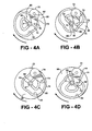
- Figure 4a is a schematic side view of a second embodiment of a linkage of the steering column assembly
- Figure 4b is a schematic side view of the second embodiment of the linkage showing movement of the linkage
- Figure 4c is a schematic side view of the second embodiment of the linkage showing movement of the linkage.
- Figure 4d is a schematic side view of the second embodiment of the linkage showing movement of the linkage.
- an adjustable steering column assembly is shown generally at 20.
- the steering column assembly 20 is for a vehicle and extends along a longitudinal axis L.
- the steering column assembly 20 comprises a column jacket 22.
- the column jacket 22 extends from a forward end 24 to a distal end 26 along the longitudinal axis L.
- a steering wheel (not shown) is mounted to the distal end 26 of the column jacket 22 as is well known in the art.
- the column jacket 22 includes an inner jacket 28 in telescopic engagement with an outer jacket 30.
- the column jacket 22 is moveable in at least one of a longitudinal direction along the longitudinal axis L, i.e., a telescopic adjustment, and a pivotable direction relative to a support bracket 32 about a pivot axis R, i.e., a rake or tilt adjustment.
- the column jacket 22 is moveable in both the longitudinal direction and the pivotable direction, but it should be appreciated that the column jacket 22 may only be moveable in one of the longitudinal direction and the pivotable direction.
- the steering column assembly 20 includes the support bracket 32, which attaches the column jacket 22 to the vehicle.
- the column jacket 22 is coupled to the support bracket 32, and the support bracket 32 couples the column jacket 22 to the vehicle.
- the support bracket 32 may include a second support bracket 33. As shown in Figure 1 , the second support bracket 33 defines a pivot axis R.
- the column jacket 22 is pivotably moveable relative to the support bracket 32 about the pivot axis R in the pivotable direction to adjust a position of the steering wheel.
- the steering column assembly 20 further comprises a compression bracket 34.
- the compression bracket 34 is mounted to the column jacket 22.
- the compression bracket 34 defines a pair of telescope slots 36 parallel to the longitudinal axis L and disposed on opposite sides of the column jacket 22, and the support bracket 32 defines a pair of pivot slots 38 extending generally vertically and transverse to the longitudinal axis L, and disposed on opposite sides of the column jacket 22 adjacent the telescope slots 36. Accordingly, there is one pivot slot 38 and one telescope slot 36 adjacent each other on each side of the column jacket 22.
- a locking mechanism 40 interconnects the support bracket 32 and the column jacket 22.
- the locking mechanism 40 is moveable between a lock position restricting the movement of the column jacket 22 and a release position permitting the moment of the column jacket 22.
- the locking mechanism 40 includes a telescope locking mechanism 42 and a pivot locking mechanism 44.
- the telescope locking mechanism 42 interconnects the support bracket 32 and the compression bracket 34, and is moveable between a telescope lock position restricting the movement of the column jacket 22 in the longitudinal direction and a telescope release position permitting the movement of the column jacket 22 in the longitudinal direction.
- the telescope locking mechanism 42 preferably includes a telescope block 46 disposed within one of the telescope slots 36 on one side of the column jacket 22.
- the telescope block 46 may include telescope teeth meshing with corresponding telescope grooves defined by the telescope slot 36 when the telescope locking mechanism 42 is in the telescope lock position. The telescope teeth are disengaged from the telescope grooves when the telescope locking mechanism 42 is in the telescope release position.
- the telescope locking mechanism 42 may include some other locking or clamping mechanism not shown or described herein, and still fall within the scope of the claims.
- the pivot locking mechanism 44 interconnects the support bracket 32 and the compression bracket 34, and is moveable between a pivot lock position restricting the movement of the column jacket 22 in the pivotable direction and a pivot release position permitting the movement of the column jacket 22 in the pivotable direction.
- the pivot locking mechanism 44 preferably includes a pivot block 52 disposed within one of the pivot slots 38 on one side of the column jacket 22, on an opposite side of the column jacket 22 relative to the telescope block 46.
- the pivot block 52 may include pivot teeth meshing with corresponding pivot grooves defined by the pivot slot 38 when the pivot locking mechanism 44 is in the pivot lock position. The pivot teeth are disengaged from the pivot grooves when the pivot locking mechanism 44 is in the pivot release position. It should be appreciated that the pivot locking mechanism 44 may include some other locking or clamping mechanism not shown or described herein, and still fall within the scope of the claims.
- the locking mechanism 40 includes a torsion shaft 58 coupled to the telescope locking mechanism 42 and the pivot locking mechanism 44.
- the torsion shaft 58 is rotatable about a shaft axis S in a first direction to move the telescope locking mechanism 42 into the telescope release position from the telescope lock position and to move the pivot locking mechanism 44 into the pivot release position from the pivot lock position.
- the torsion shaft 58 is rotatable about the shaft axis S in a second direction to move the telescope locking mechanism 42 into the telescope lock position from the telescope release position and to move the pivot locking mechanism 44 into the pivot lock position from pivot rake release position.
- the torsion shaft 58 extends through the telescope slot 36 and the pivot slot 38 on one side of the column jacket 22, across the column jacket 22, and through the telescope slot 36 and pivot slot 38 on the other side of the column jacket 22.
- the torsion shaft 58 typically activates a cam mechanism 60 for each of the telescope locking mechanism 42 and the pivot locking mechanism 44 to move the telescope block 46 and the pivot block 52 between the lock position and the release position in response to rotation of the torsion shaft 58, as is well known.
- a motor 62 is coupled to the column jacket 22.
- the motor 62 includes an output shaft 64, which is rotatable about a primary axis P in a single rotational direction, i.e., the motor 62 only rotates in one direction.
- the motor 62 includes an electric motor 62.
- the motor 62 may be powered by some other source other than electricity.
- a linkage 66 interconnects the output shaft 64 of the motor 62 and the locking mechanism 40.
- the linkage 66 is actuated by the rotation of the output shaft 64 in the single rotational direction to move the locking mechanism 40 in alternating fashion between the lock position and the release position.
- the linkage 66 is attached to the torsion shaft 58, and the motor 62, when activated, continuously rotates in the single rotational direction with the linkage 66 causing alternating rotation of the torsion shaft 58 between the first direction and the second direction.
- the linkage 66 includes a plate 68 attached to and concentric with the output shaft 64.
- the plate 68 extends radially outward from the output shaft 64 for rotation with the output shaft 64.
- the linkage 66 further includes a lever 70 mounted to the locking mechanism 40 and coupled to the plate 68.
- the lever 70 includes a first end 72 adjacent the locking mechanism 40 and a second end 74 adjacent the plate 68.
- a peg 76 interconnects the plate 68 and the lever 70. The peg 76 is radially spaced from the primary axis P of the output shaft 64.
- the peg 76 is fixedly mounted to the plate 68. Accordingly, the peg 76 rotates with the plate 68 to define a circular path about the primary axis P of the output shaft 64.
- the first end 72 of the lever 70 is mounted to the locking mechanism 40, and as shown, is fixedly attached to the torsion shaft 58. Accordingly, the first end 72 of the lever 70 is substantially fixed relative to the output shaft 64.
- the second end 74 of the lever 70 defines an elongated slot 78 extending transverse to the primary axis P.
- the peg 76 extends through the elongated slot 78, and is moveable within the elongated slot 78 in response to rotation of the plate 68 about the primary axis P.
- Movement of the peg 76 about the primary axis P drives the lever 70 to move the lever 70 in a back and forth motion transverse to the shaft axis S. Therefore, as the peg 76 travels along the circular path, the second end 74 of the lever 70 moves back and forth in a transverse direction relative to the primary axis P, thereby alternatively rotating the torsion shaft 58 in between the first direction and the second direction, while the peg 76 simultaneously moves for and aft within the elongated slot 78.
- the first end 72 of the lever 70 is rotated about the shaft axis S as the peg 76 travels through one hundred eight degrees (180°) of the circular path, and is rotated about the shaft axis S as the peg 76 travels through the remaining one hundred eight degrees (180°) of the circular path.
- the first alternative embodiment of the linkage 80 includes the peg 76 being fixedly attached to the lever 70.
- the plate 68 defines an eccentric cam groove 82 radially about the primary axis P with the peg 76 disposed within the eccentric cam groove 82.
- the peg 76 is moveable within the eccentric cam groove 82 in response to rotation of the plate 68 about the primary axis P to move the lever 70 in a back and forth motion transverse to the shaft axis S.
- the eccentric cam groove 82 includes a generally triangular shape and is disposed on a face of the plate 68.
- the output shaft 64 and the primary axis P are substantially located at an apex 84 of the generally triangular shaped eccentric cam groove 82.
- the peg 76 follows the eccentric cam groove 82 in a path that repeatedly moves the second end 74 of the lever 70 nearer to and away from the output shaft 64, resulting in alternating rotation of the first end 72 of the lever 70 about the shaft axis S of the torsion shaft 58.
Landscapes
- Engineering & Computer Science (AREA)
- Chemical & Material Sciences (AREA)
- Combustion & Propulsion (AREA)
- Transportation (AREA)
- Mechanical Engineering (AREA)
- Steering Controls (AREA)
Applications Claiming Priority (1)
| Application Number | Priority Date | Filing Date | Title |
|---|---|---|---|
| US12/114,394 US8056437B2 (en) | 2005-04-19 | 2008-05-02 | Electric steering column lock with single direction actuator travel |
Publications (3)
| Publication Number | Publication Date |
|---|---|
| EP2113441A2 true EP2113441A2 (de) | 2009-11-04 |
| EP2113441A3 EP2113441A3 (de) | 2010-01-20 |
| EP2113441B1 EP2113441B1 (de) | 2012-06-20 |
Family
ID=40786762
Family Applications (1)
| Application Number | Title | Priority Date | Filing Date |
|---|---|---|---|
| EP09158470A Not-in-force EP2113441B1 (de) | 2008-05-02 | 2009-04-22 | Elektrische Lenksäulenklemmeinrichtung mit Aktuatorbewegung in eine Richtung |
Country Status (2)
| Country | Link |
|---|---|
| US (2) | US8056437B2 (de) |
| EP (1) | EP2113441B1 (de) |
Families Citing this family (18)
| Publication number | Priority date | Publication date | Assignee | Title |
|---|---|---|---|---|
| JP4624912B2 (ja) * | 2005-11-30 | 2011-02-02 | 株式会社アルファ | 電動ステアリングロック装置 |
| US8424348B2 (en) * | 2010-01-27 | 2013-04-23 | Strattec Security Corporation | Steering lock |
| US8584541B2 (en) * | 2011-02-25 | 2013-11-19 | Delphi Technologies, Inc. | Anti-backlash/anti-rattle lever |
| US8997600B2 (en) * | 2011-05-18 | 2015-04-07 | Nsk Ltd. | Steering apparatus for an automobile |
| DE102013217735A1 (de) | 2012-09-07 | 2014-03-13 | Strattec Security Corporation | Lenkschloss |
| DE102013225117A1 (de) * | 2013-12-06 | 2015-06-11 | Richard Wolf Gmbh | Antriebsanordnung für ein endoskopisches Schaftinstrument |
| US10589774B2 (en) | 2015-05-01 | 2020-03-17 | Steering Solutions Ip Holding Corporation | Counter rotation steering wheel |
| DE102015007784B4 (de) * | 2015-06-19 | 2020-02-13 | Thyssenkrupp Ag | Lenksäule mit elektro-mechanischer Fixiervorrichtung |
| US20160375931A1 (en) | 2015-06-25 | 2016-12-29 | Steering Solutions Ip Holding Corporation | Rotation control system for a steering wheel and method |
| US10160472B2 (en) | 2015-10-20 | 2018-12-25 | Steering Solutions Ip Holding Corporation | Steering column with stationary hub |
| US10228047B2 (en) * | 2016-06-17 | 2019-03-12 | Robert Bosch Llc | Actuator for providing relative motion between two points |
| DE102016008561A1 (de) * | 2016-07-14 | 2018-01-18 | Thyssenkrupp Ag | Lenksäule mit elektro-mechanischer Fixiervorrichtung |
| US10160473B2 (en) * | 2016-09-13 | 2018-12-25 | Steering Solutions Ip Holding Corporation | Steering column decoupling system |
| GB2566704A (en) * | 2017-09-21 | 2019-03-27 | Ford Global Tech Llc | A steering assembly |
| US11034377B2 (en) * | 2018-07-31 | 2021-06-15 | Steering Solutions Ip Holding Corporation | System and method of automatically stowing and unstowing a steering column assembly |
| US11292504B2 (en) * | 2019-03-20 | 2022-04-05 | Volvo Car Corporation | Vehicle having multiple driving positions |
| DE102019122321A1 (de) * | 2019-08-20 | 2021-02-25 | Thyssenkrupp Ag | Lenksäule für ein Kraftfahrzeug mit Umdrehungsbegrenzung |
| DE102019122320A1 (de) | 2019-08-20 | 2021-02-25 | Thyssenkrupp Ag | Lenksäule für ein Kraftfahrzeug mit Umdrehungsbegrenzung |
Citations (1)
| Publication number | Priority date | Publication date | Assignee | Title |
|---|---|---|---|---|
| US7055860B2 (en) | 2002-06-27 | 2006-06-06 | Delphi Technologies, Inc. | Electrically actuated steering column mechanism |
Family Cites Families (35)
| Publication number | Priority date | Publication date | Assignee | Title |
|---|---|---|---|---|
| US2153998A (en) | 1937-02-18 | 1939-04-11 | Verderber Joseph | Cam mechanism |
| US3711139A (en) | 1969-12-30 | 1973-01-16 | Us Navy | Pressure actuated spring biased latch |
| US4244237A (en) | 1979-05-29 | 1981-01-13 | International Harvester Company | Tilt steering column mechanism |
| DE3017402A1 (de) | 1980-05-07 | 1981-11-12 | Fichtel & Sachs Ag, 8720 Schweinfurt | Elektromotorische zentralverriegelungs-einrichtung mit diebstahlsicherung fuer tueren, insbesondere kraftfahrzeugtueren |
| DE3421795C2 (de) * | 1983-06-13 | 1987-05-07 | Aisin Seiki K.K., Kariya, Aichi | Verschwenkbare Lenkeinheit |
| DE3619125C1 (de) | 1986-06-06 | 1987-10-22 | Daimler Benz Ag | Aufnahmevorrichtung fuer eine verstellbare Lenksaeule eines Kraftwagens |
| US4810014A (en) * | 1987-08-20 | 1989-03-07 | Mcgourty Thomas K | Motor driven lock control |
| JPH03227754A (ja) | 1990-01-31 | 1991-10-08 | Nippondenso Co Ltd | 乗員保護装置 |
| JP3227754B2 (ja) | 1992-01-17 | 2001-11-12 | ヤマハ株式会社 | 半導体記憶装置とその製法 |
| US5301567A (en) | 1992-09-23 | 1994-04-12 | Chrysler Corporation | Low pivot tilt steering column clamping mechanism |
| US5562306A (en) | 1994-03-18 | 1996-10-08 | Dr. Ing. H.C.F. Porsche Ag | Adjustable steering device |
| US5722299A (en) | 1994-06-30 | 1998-03-03 | Fuji Kiko Co., Ltd. | Adjustable steering column assembly for a vehicle |
| US5829311A (en) | 1996-08-15 | 1998-11-03 | Roberson; Jarried E. | Motorized tilt steering device |
| DE19638282C1 (de) | 1996-09-19 | 1998-02-19 | Lemfoerder Metallwaren Ag | Klemmvorrichtung für eine verstellbare Lenksäule eines Kraftfahrzeuges |
| GB9704808D0 (en) | 1997-03-07 | 1997-04-23 | Lucas Ind Plc | Improvements relating to steering assemblies |
| GB9713356D0 (en) | 1997-06-24 | 1997-08-27 | Nastech Europ Ltd | Adjustable steering column clamping mechanism |
| FR2780934B1 (fr) | 1998-07-13 | 2001-05-04 | Lemforder Nacam Sa | Dispositif de serrage a commande electrique pour un systeme de reglage en position d'un element par rapport a un autre element |
| SE521827C2 (sv) | 1998-11-27 | 2003-12-09 | Volvo Personvagnar Ab | Arrangemang vid styrinrättning |
| US6139057A (en) | 1999-02-04 | 2000-10-31 | Delphi Technologies, Inc. | Position control apparatus for steering column |
| GB2350329B (en) | 1999-05-26 | 2002-08-07 | Nastech Europ Ltd | Collapsible steering column assembly for a vehicle |
| GB2352284A (en) | 1999-07-19 | 2001-01-24 | Delphi Tech Inc | Clamping device for a steering column |
| US6419269B1 (en) | 1999-09-20 | 2002-07-16 | Delphi Technologies | Locking system for adjustable position steering column |
| US6659504B2 (en) | 2001-05-18 | 2003-12-09 | Delphi Technologies, Inc. | Steering column for a vehicle |
| DE10152807A1 (de) | 2001-10-25 | 2003-05-15 | Daimler Chrysler Ag | Klemm-Mechanismus für eine verstellbare Lenksäule |
| DE10156327A1 (de) | 2001-11-19 | 2003-06-05 | Zf Lenksysteme Gmbh | Einstellbare Lenksäule |
| US7331608B2 (en) | 2002-06-27 | 2008-02-19 | Delphi Technologies, Inc. | Electrically actuated steering column mechanism |
| US6792824B2 (en) | 2002-08-24 | 2004-09-21 | Daimlerchrysler Corporation | Tilt-telescope steering column |
| DE10333228A1 (de) | 2003-07-21 | 2005-02-24 | Thyssenkrupp Presta Ag | Feststelleinrichtung einer in mindestens eine Verstellrichtung verstellbaren Lenksäule |
| DE10341419A1 (de) | 2003-09-09 | 2005-03-31 | Daimlerchrysler Ag | Kraftfahrzeuglenksäuleneinheit |
| US7178422B2 (en) | 2004-07-02 | 2007-02-20 | Delphi Technologies, Inc. | Electrical tilt and telescope locking mechanism |
| US7484430B2 (en) | 2004-07-27 | 2009-02-03 | Delphi Technologies, Inc. | Telescope feature used for energy absorption |
| US20060230863A1 (en) | 2005-04-19 | 2006-10-19 | Delphi Technologies, Inc. | Steering column with rake and telescope adjustment |
| US7631898B2 (en) | 2006-01-25 | 2009-12-15 | Chrysler Group Llc | Power release and locking adjustable steering column apparatus and method |
| US7533594B2 (en) | 2006-12-13 | 2009-05-19 | Delphi Technologies, Inc. | Position control apparatus for steering column |
| US7574941B2 (en) | 2007-02-20 | 2009-08-18 | Delphi Technologies, Inc. | Adjustable steering column assembly having a rake and telescope locking system |
-
2008
- 2008-05-02 US US12/114,394 patent/US8056437B2/en active Active
-
2009
- 2009-04-22 EP EP09158470A patent/EP2113441B1/de not_active Not-in-force
-
2011
- 2011-09-30 US US13/249,705 patent/US8220355B2/en not_active Expired - Lifetime
Patent Citations (1)
| Publication number | Priority date | Publication date | Assignee | Title |
|---|---|---|---|---|
| US7055860B2 (en) | 2002-06-27 | 2006-06-06 | Delphi Technologies, Inc. | Electrically actuated steering column mechanism |
Also Published As
| Publication number | Publication date |
|---|---|
| US8056437B2 (en) | 2011-11-15 |
| EP2113441B1 (de) | 2012-06-20 |
| US20120017719A1 (en) | 2012-01-26 |
| EP2113441A3 (de) | 2010-01-20 |
| US20080202275A1 (en) | 2008-08-28 |
| US8220355B2 (en) | 2012-07-17 |
Similar Documents
| Publication | Publication Date | Title |
|---|---|---|
| EP2113441B1 (de) | Elektrische Lenksäulenklemmeinrichtung mit Aktuatorbewegung in eine Richtung | |
| US7770487B2 (en) | Vehicle steering column structure | |
| JP5286861B2 (ja) | 運動変換駆動装置及びその運動変換駆動装置を備えた車両用シート装置 | |
| US20120025582A1 (en) | Seat assembly having an adjustable head restraint assembly | |
| US7666038B2 (en) | Steering arm structure of outboard motor | |
| US7178422B2 (en) | Electrical tilt and telescope locking mechanism | |
| EP2011718B1 (de) | Fahrzeug-Lenksäule | |
| EP1386820B1 (de) | Neigungsverstellbare Lenksäulen-Baugruppe | |
| EP2236348A2 (de) | Sitzneigungsverstellungsvorrichtung | |
| CN102556150B (zh) | 单一电机式的电机驱动柱装置 | |
| US6814406B2 (en) | Seat vertical position adjusting device | |
| JP4894413B2 (ja) | ステアリング装置 | |
| JPWO2007083536A1 (ja) | ステアリングコラム装置 | |
| EP2993108B1 (de) | Lenkvorrichtung | |
| US7743681B2 (en) | Steering column assembly having an actuation mechanism for telescoping and tilting movement | |
| EP1714849A3 (de) | Lenksäule mit Verstellung in Höhe und Länge | |
| JP4641432B2 (ja) | ハンドル装置 | |
| JP2010246805A (ja) | 車両用シート | |
| CN113939439A (zh) | 转向柱强制锁定驱动机构 | |
| US7370554B2 (en) | Moveable control pedal assembly | |
| US7823479B2 (en) | Vehicle steering column structure | |
| JPH07334262A (ja) | 前後調節可能な操作ペダル装置 | |
| US8960048B2 (en) | Accelerator pedal adjustment mechanism | |
| JP4608732B2 (ja) | リクライニング位置検出装置 | |
| JP2010100143A (ja) | 車両用操舵装置 |
Legal Events
| Date | Code | Title | Description |
|---|---|---|---|
| PUAI | Public reference made under article 153(3) epc to a published international application that has entered the european phase |
Free format text: ORIGINAL CODE: 0009012 |
|
| AK | Designated contracting states |
Kind code of ref document: A2 Designated state(s): AT BE BG CH CY CZ DE DK EE ES FI FR GB GR HR HU IE IS IT LI LT LU LV MC MK MT NL NO PL PT RO SE SI SK TR |
|
| PUAL | Search report despatched |
Free format text: ORIGINAL CODE: 0009013 |
|
| AK | Designated contracting states |
Kind code of ref document: A3 Designated state(s): AT BE BG CH CY CZ DE DK EE ES FI FR GB GR HR HU IE IS IT LI LT LU LV MC MK MT NL NO PL PT RO SE SI SK TR |
|
| 17P | Request for examination filed |
Effective date: 20100422 |
|
| 17Q | First examination report despatched |
Effective date: 20100618 |
|
| RAP1 | Party data changed (applicant data changed or rights of an application transferred) |
Owner name: GM GLOBAL TECHNOLOGY OPERATIONS, INC. |
|
| RAP1 | Party data changed (applicant data changed or rights of an application transferred) |
Owner name: GM GLOBAL TECHNOLOGY OPERATIONS LLC |
|
| GRAP | Despatch of communication of intention to grant a patent |
Free format text: ORIGINAL CODE: EPIDOSNIGR1 |
|
| GRAS | Grant fee paid |
Free format text: ORIGINAL CODE: EPIDOSNIGR3 |
|
| GRAA | (expected) grant |
Free format text: ORIGINAL CODE: 0009210 |
|
| AK | Designated contracting states |
Kind code of ref document: B1 Designated state(s): AT BE BG CH CY CZ DE DK EE ES FI FR GB GR HR HU IE IS IT LI LT LU LV MC MK MT NL NO PL PT RO SE SI SK TR |
|
| REG | Reference to a national code |
Ref country code: GB Ref legal event code: FG4D |
|
| REG | Reference to a national code |
Ref country code: CH Ref legal event code: EP |
|
| REG | Reference to a national code |
Ref country code: AT Ref legal event code: REF Ref document number: 562892 Country of ref document: AT Kind code of ref document: T Effective date: 20120715 |
|
| REG | Reference to a national code |
Ref country code: IE Ref legal event code: FG4D |
|
| REG | Reference to a national code |
Ref country code: DE Ref legal event code: R096 Ref document number: 602009007634 Country of ref document: DE Effective date: 20120816 |
|
| PG25 | Lapsed in a contracting state [announced via postgrant information from national office to epo] |
Ref country code: SE Free format text: LAPSE BECAUSE OF FAILURE TO SUBMIT A TRANSLATION OF THE DESCRIPTION OR TO PAY THE FEE WITHIN THE PRESCRIBED TIME-LIMIT Effective date: 20120620 Ref country code: LT Free format text: LAPSE BECAUSE OF FAILURE TO SUBMIT A TRANSLATION OF THE DESCRIPTION OR TO PAY THE FEE WITHIN THE PRESCRIBED TIME-LIMIT Effective date: 20120620 Ref country code: FI Free format text: LAPSE BECAUSE OF FAILURE TO SUBMIT A TRANSLATION OF THE DESCRIPTION OR TO PAY THE FEE WITHIN THE PRESCRIBED TIME-LIMIT Effective date: 20120620 Ref country code: NO Free format text: LAPSE BECAUSE OF FAILURE TO SUBMIT A TRANSLATION OF THE DESCRIPTION OR TO PAY THE FEE WITHIN THE PRESCRIBED TIME-LIMIT Effective date: 20120920 |
|
| REG | Reference to a national code |
Ref country code: NL Ref legal event code: VDEP Effective date: 20120620 |
|
| REG | Reference to a national code |
Ref country code: AT Ref legal event code: MK05 Ref document number: 562892 Country of ref document: AT Kind code of ref document: T Effective date: 20120620 |
|
| REG | Reference to a national code |
Ref country code: LT Ref legal event code: MG4D Effective date: 20120620 |
|
| PG25 | Lapsed in a contracting state [announced via postgrant information from national office to epo] |
Ref country code: GR Free format text: LAPSE BECAUSE OF FAILURE TO SUBMIT A TRANSLATION OF THE DESCRIPTION OR TO PAY THE FEE WITHIN THE PRESCRIBED TIME-LIMIT Effective date: 20120921 Ref country code: SI Free format text: LAPSE BECAUSE OF FAILURE TO SUBMIT A TRANSLATION OF THE DESCRIPTION OR TO PAY THE FEE WITHIN THE PRESCRIBED TIME-LIMIT Effective date: 20120620 Ref country code: HR Free format text: LAPSE BECAUSE OF FAILURE TO SUBMIT A TRANSLATION OF THE DESCRIPTION OR TO PAY THE FEE WITHIN THE PRESCRIBED TIME-LIMIT Effective date: 20120620 Ref country code: LV Free format text: LAPSE BECAUSE OF FAILURE TO SUBMIT A TRANSLATION OF THE DESCRIPTION OR TO PAY THE FEE WITHIN THE PRESCRIBED TIME-LIMIT Effective date: 20120620 |
|
| RAP2 | Party data changed (patent owner data changed or rights of a patent transferred) |
Owner name: GM GLOBAL TECHNOLOGY OPERATIONS LLC Owner name: STEERING SOLUTIONS IP HOLDING CORPORATION |
|
| PG25 | Lapsed in a contracting state [announced via postgrant information from national office to epo] |
Ref country code: CZ Free format text: LAPSE BECAUSE OF FAILURE TO SUBMIT A TRANSLATION OF THE DESCRIPTION OR TO PAY THE FEE WITHIN THE PRESCRIBED TIME-LIMIT Effective date: 20120620 Ref country code: BE Free format text: LAPSE BECAUSE OF FAILURE TO SUBMIT A TRANSLATION OF THE DESCRIPTION OR TO PAY THE FEE WITHIN THE PRESCRIBED TIME-LIMIT Effective date: 20120620 Ref country code: RO Free format text: LAPSE BECAUSE OF FAILURE TO SUBMIT A TRANSLATION OF THE DESCRIPTION OR TO PAY THE FEE WITHIN THE PRESCRIBED TIME-LIMIT Effective date: 20120620 Ref country code: IS Free format text: LAPSE BECAUSE OF FAILURE TO SUBMIT A TRANSLATION OF THE DESCRIPTION OR TO PAY THE FEE WITHIN THE PRESCRIBED TIME-LIMIT Effective date: 20121020 Ref country code: CY Free format text: LAPSE BECAUSE OF FAILURE TO SUBMIT A TRANSLATION OF THE DESCRIPTION OR TO PAY THE FEE WITHIN THE PRESCRIBED TIME-LIMIT Effective date: 20120620 Ref country code: AT Free format text: LAPSE BECAUSE OF FAILURE TO SUBMIT A TRANSLATION OF THE DESCRIPTION OR TO PAY THE FEE WITHIN THE PRESCRIBED TIME-LIMIT Effective date: 20120620 Ref country code: SK Free format text: LAPSE BECAUSE OF FAILURE TO SUBMIT A TRANSLATION OF THE DESCRIPTION OR TO PAY THE FEE WITHIN THE PRESCRIBED TIME-LIMIT Effective date: 20120620 Ref country code: EE Free format text: LAPSE BECAUSE OF FAILURE TO SUBMIT A TRANSLATION OF THE DESCRIPTION OR TO PAY THE FEE WITHIN THE PRESCRIBED TIME-LIMIT Effective date: 20120620 |
|
| PG25 | Lapsed in a contracting state [announced via postgrant information from national office to epo] |
Ref country code: PL Free format text: LAPSE BECAUSE OF FAILURE TO SUBMIT A TRANSLATION OF THE DESCRIPTION OR TO PAY THE FEE WITHIN THE PRESCRIBED TIME-LIMIT Effective date: 20120620 Ref country code: PT Free format text: LAPSE BECAUSE OF FAILURE TO SUBMIT A TRANSLATION OF THE DESCRIPTION OR TO PAY THE FEE WITHIN THE PRESCRIBED TIME-LIMIT Effective date: 20121022 Ref country code: IT Free format text: LAPSE BECAUSE OF FAILURE TO SUBMIT A TRANSLATION OF THE DESCRIPTION OR TO PAY THE FEE WITHIN THE PRESCRIBED TIME-LIMIT Effective date: 20120620 |
|
| REG | Reference to a national code |
Ref country code: DE Ref legal event code: R082 Ref document number: 602009007634 Country of ref document: DE Representative=s name: MANITZ, FINSTERWALD & PARTNER GBR, DE |
|
| PG25 | Lapsed in a contracting state [announced via postgrant information from national office to epo] |
Ref country code: NL Free format text: LAPSE BECAUSE OF FAILURE TO SUBMIT A TRANSLATION OF THE DESCRIPTION OR TO PAY THE FEE WITHIN THE PRESCRIBED TIME-LIMIT Effective date: 20120620 |
|
| PLBE | No opposition filed within time limit |
Free format text: ORIGINAL CODE: 0009261 |
|
| STAA | Information on the status of an ep patent application or granted ep patent |
Free format text: STATUS: NO OPPOSITION FILED WITHIN TIME LIMIT |
|
| PG25 | Lapsed in a contracting state [announced via postgrant information from national office to epo] |
Ref country code: ES Free format text: LAPSE BECAUSE OF FAILURE TO SUBMIT A TRANSLATION OF THE DESCRIPTION OR TO PAY THE FEE WITHIN THE PRESCRIBED TIME-LIMIT Effective date: 20121001 Ref country code: DK Free format text: LAPSE BECAUSE OF FAILURE TO SUBMIT A TRANSLATION OF THE DESCRIPTION OR TO PAY THE FEE WITHIN THE PRESCRIBED TIME-LIMIT Effective date: 20120620 |
|
| REG | Reference to a national code |
Ref country code: DE Ref legal event code: R081 Ref document number: 602009007634 Country of ref document: DE Owner name: STEERING SOLUTIONS IP HOLDING CORP., US Free format text: FORMER OWNER: GM GLOBAL TECHNOLOGY OPERATIONS, LLC, DETROIT, US Effective date: 20130313 Ref country code: DE Ref legal event code: R081 Ref document number: 602009007634 Country of ref document: DE Owner name: GM GLOBAL TECHNOLOGY OPERATIONS LLC (N. D. GES, US Free format text: FORMER OWNER: GM GLOBAL TECHNOLOGY OPERATIONS, LLC, DETROIT, US Effective date: 20130313 Ref country code: DE Ref legal event code: R082 Ref document number: 602009007634 Country of ref document: DE Representative=s name: MANITZ, FINSTERWALD & PARTNER GBR, DE Effective date: 20130313 Ref country code: DE Ref legal event code: R081 Ref document number: 602009007634 Country of ref document: DE Owner name: STEERING SOLUTIONS IP HOLDING CORP., SAGINAW, US Free format text: FORMER OWNER: GM GLOBAL TECHNOLOGY OPERATIONS, LLC, DETROIT, MICH., US Effective date: 20130313 Ref country code: DE Ref legal event code: R081 Ref document number: 602009007634 Country of ref document: DE Owner name: GM GLOBAL TECHNOLOGY OPERATIONS LLC (N. D. GES, US Free format text: FORMER OWNER: GM GLOBAL TECHNOLOGY OPERATIONS, LLC, DETROIT, MICH., US Effective date: 20130313 |
|
| 26N | No opposition filed |
Effective date: 20130321 |
|
| REG | Reference to a national code |
Ref country code: DE Ref legal event code: R097 Ref document number: 602009007634 Country of ref document: DE Effective date: 20130321 |
|
| PG25 | Lapsed in a contracting state [announced via postgrant information from national office to epo] |
Ref country code: BG Free format text: LAPSE BECAUSE OF FAILURE TO SUBMIT A TRANSLATION OF THE DESCRIPTION OR TO PAY THE FEE WITHIN THE PRESCRIBED TIME-LIMIT Effective date: 20120920 |
|
| PGFP | Annual fee paid to national office [announced via postgrant information from national office to epo] |
Ref country code: DE Payment date: 20130429 Year of fee payment: 5 |
|
| PG25 | Lapsed in a contracting state [announced via postgrant information from national office to epo] |
Ref country code: MC Free format text: LAPSE BECAUSE OF FAILURE TO SUBMIT A TRANSLATION OF THE DESCRIPTION OR TO PAY THE FEE WITHIN THE PRESCRIBED TIME-LIMIT Effective date: 20120620 |
|
| REG | Reference to a national code |
Ref country code: CH Ref legal event code: PL |
|
| GBPC | Gb: european patent ceased through non-payment of renewal fee |
Effective date: 20130422 |
|
| REG | Reference to a national code |
Ref country code: IE Ref legal event code: MM4A |
|
| PG25 | Lapsed in a contracting state [announced via postgrant information from national office to epo] |
Ref country code: CH Free format text: LAPSE BECAUSE OF NON-PAYMENT OF DUE FEES Effective date: 20130430 Ref country code: LI Free format text: LAPSE BECAUSE OF NON-PAYMENT OF DUE FEES Effective date: 20130430 Ref country code: GB Free format text: LAPSE BECAUSE OF NON-PAYMENT OF DUE FEES Effective date: 20130422 |
|
| REG | Reference to a national code |
Ref country code: FR Ref legal event code: ST Effective date: 20131231 |
|
| PG25 | Lapsed in a contracting state [announced via postgrant information from national office to epo] |
Ref country code: FR Free format text: LAPSE BECAUSE OF NON-PAYMENT OF DUE FEES Effective date: 20130430 |
|
| PG25 | Lapsed in a contracting state [announced via postgrant information from national office to epo] |
Ref country code: IE Free format text: LAPSE BECAUSE OF NON-PAYMENT OF DUE FEES Effective date: 20130422 |
|
| REG | Reference to a national code |
Ref country code: DE Ref legal event code: R119 Ref document number: 602009007634 Country of ref document: DE |
|
| REG | Reference to a national code |
Ref country code: DE Ref legal event code: R119 Ref document number: 602009007634 Country of ref document: DE Effective date: 20141101 |
|
| PG25 | Lapsed in a contracting state [announced via postgrant information from national office to epo] |
Ref country code: DE Free format text: LAPSE BECAUSE OF NON-PAYMENT OF DUE FEES Effective date: 20141101 |
|
| PG25 | Lapsed in a contracting state [announced via postgrant information from national office to epo] |
Ref country code: MT Free format text: LAPSE BECAUSE OF FAILURE TO SUBMIT A TRANSLATION OF THE DESCRIPTION OR TO PAY THE FEE WITHIN THE PRESCRIBED TIME-LIMIT Effective date: 20120620 |
|
| PG25 | Lapsed in a contracting state [announced via postgrant information from national office to epo] |
Ref country code: TR Free format text: LAPSE BECAUSE OF FAILURE TO SUBMIT A TRANSLATION OF THE DESCRIPTION OR TO PAY THE FEE WITHIN THE PRESCRIBED TIME-LIMIT Effective date: 20120620 |
|
| PG25 | Lapsed in a contracting state [announced via postgrant information from national office to epo] |
Ref country code: LU Free format text: LAPSE BECAUSE OF NON-PAYMENT OF DUE FEES Effective date: 20130422 Ref country code: HU Free format text: LAPSE BECAUSE OF FAILURE TO SUBMIT A TRANSLATION OF THE DESCRIPTION OR TO PAY THE FEE WITHIN THE PRESCRIBED TIME-LIMIT; INVALID AB INITIO Effective date: 20090422 Ref country code: MK Free format text: LAPSE BECAUSE OF FAILURE TO SUBMIT A TRANSLATION OF THE DESCRIPTION OR TO PAY THE FEE WITHIN THE PRESCRIBED TIME-LIMIT Effective date: 20120620 |