EP2112840A2 - Electret condenser microphone - Google Patents
Electret condenser microphone Download PDFInfo
- Publication number
- EP2112840A2 EP2112840A2 EP09251174A EP09251174A EP2112840A2 EP 2112840 A2 EP2112840 A2 EP 2112840A2 EP 09251174 A EP09251174 A EP 09251174A EP 09251174 A EP09251174 A EP 09251174A EP 2112840 A2 EP2112840 A2 EP 2112840A2
- Authority
- EP
- European Patent Office
- Prior art keywords
- backplate
- diaphragm
- frame
- spacer
- capsule
- Prior art date
- Legal status (The legal status is an assumption and is not a legal conclusion. Google has not performed a legal analysis and makes no representation as to the accuracy of the status listed.)
- Ceased
Links
Images

Classifications
-
- H—ELECTRICITY
- H04—ELECTRIC COMMUNICATION TECHNIQUE
- H04R—LOUDSPEAKERS, MICROPHONES, GRAMOPHONE PICK-UPS OR LIKE ACOUSTIC ELECTROMECHANICAL TRANSDUCERS; DEAF-AID SETS; PUBLIC ADDRESS SYSTEMS
- H04R19/00—Electrostatic transducers
- H04R19/01—Electrostatic transducers characterised by the use of electrets
- H04R19/016—Electrostatic transducers characterised by the use of electrets for microphones
Definitions
- the present invention relates to electret condenser microphones.
- a conventional electret condenser microphone has a frame affixed with a vibratory diaphragm and a backplate disposed substantially parallel to the diaphragm with a predetermined space reserved therebetween, as disclosed in Japanese Unexamined Patent Publication No. 2000-050393 and Japanese Unexamined Patent Publication No. 2004-222091 .
- the frame and the backplate have substantially the same outer diameters and are vertically stacked one on top of the other. This structure is a bottleneck in reducing the thickness of the conventional electret condenser microphone.
- the present invention was made in view of the foregoing circumstances.
- the invention provides an electret condenser microphone in which the frame and the backplate can be disposed at substantially the same level for reducing the thickness of the microphone.
- an electret condenser microphone includes a diaphragm, a frame adapted to have the diaphragm affixed thereto, and a backplate positionable inside the frame and opposite the diaphragm with a space reserved or defined therebetween, said backplate having an electret layer on its surface facing the diaphragm and a through-hole penetrating the backplate and the electret layer communicating with the space.
- the backplate is disposed inside the frame. That is, the frame and the backplate are positioned substantially level with each other, making it possible to reduce the thickness of the microphone as compared with the conventional exemplary microphones.
- the microphone may further include a spacer to be provided at a surface of the backplate opposite the diaphragm so as to reserve or define the space between the backplate and the diaphragm.
- a spacer to be provided at a surface of the backplate opposite the diaphragm so as to reserve or define the space between the backplate and the diaphragm.
- this aspect of the invention enables reduction of the space between the diaphragm and the backplate and improves sensitivity of the diaphragm.
- increased tension of the diaphragm helps to reduce undesirable variations in tension between diaphragms produced by affixing a film to a plurality of frames.
- a plurality of frames may be affixed to a single film, which may be cut apart to form a plurality of diaphragms affixed to the respective frames.
- this aspect of the invention can reduce the variations because each diaphragm is pressed by the backplate via the spacer.
- the backplate be adapted to press the diaphragm via the spacer from the first surface side of the frame.
- the microphone may further include a capsule for accommodating the frame.
- the capsule may have a protruded portion to be disposed inside the frame and to function as the backplate.
- the microphone having the backplate as the protruded portion of the capsule may be manufactured with reduced number of components and in fewer assembly man-hours, in comparison with a case in which the backplate is provided as a discrete component. Consequently, this aspect of the invention is advantageous in cost reduction.
- the capsule may accommodate the backplate as well as the frame.
- Such capsule may have a positioning means for positioning and holding the backplate.
- the capsule may accommodate the spacer in addition to the frame and the backplate.
- Such capsule may include a positioning means, and the backplate as held by the positioning means is adapted to press the diaphragm.
- the positioning means of either type makes it easy to position and hold the backplate, facilitating attachment of the backplate.
- the electret condenser microphone as shown in Fig. 1 is a back electret condenser microphone.
- the electret condenser microphone includes a frame 100 having a diaphragm 110 affixed thereto, a backplate 200, a spacer 300, a printed circuit board (PCB) 400, a field-effect transistor (FET) 500, an electrically conductive ring 600, and a capsule 700 containing all the other components.
- PCB printed circuit board
- FET field-effect transistor
- the frame 100 is a circular electrically conductive ring.
- the frame 100 is set on an electrically isolated portion (not shown) of a bottom plate 710 (to be described below) of the capsule 700.
- the diaphragm 110 is made of a well-known metal thin film.
- the diaphragm 110 is affixed to a lower surface 101 (a first surface) of the frame 100 with conductive adhesive.
- the ring 600 (gate ring) is an annular member having substantially the same outer diameter as that of the frame 100.
- the ring 600 is disposed on an upper surface 102 of the frame 100 and is interposed between the PCB 400 and the frame 100.
- the PCB 400 is a well-known circular circuit board and is disposed above the frame 100 and the ring 600.
- the PCB 400 has substantially the same outer diameter as that of the frame 100.
- the PCB 400 is provided with first and second conductive lines (not shown).
- the first conductive line contacts the ring 600, while connecting to a gate terminal of the FET 500 that is mounted at the center of a lower surface of the PCB 400.
- the second conductive line contacts a swaged portion 730 (to be described below) of the capsule 700 for connection with a ground terminal (not shown).
- the spacer 300 is an insulative ring formed on the peripheral edge of an upper surface of the backplate 200. As described below, the spacer 300 is interposed between the diaphragm 110 and the backplate 200 so as to define a predetermined space C therebetween.
- the backplate 200 is a circular conductive metal plate.
- the backplate 200 has an outer diameter that is smaller than the inner diameter of the frame 100 and a thickness that is substantially the same as the thickness of the frame 100.
- an electret layer 201 On the upper surface (the surface opposing the diaphragm) of the backplate 200, there is formed an electret layer 201, which may be a thin film of polymer such as fluorinated ethylene propylene (FEP).
- FEP fluorinated ethylene propylene
- the backplate 200 is disposed inside the frame 100.
- the backplate 200 presses the diaphragm 110 via the spacer 300 from below (from the first surface side of the frame) by the combined thickness of the backplate 200 and spacer 300.
- a space C (capacitor) having the thickness of the spacer 300 is thereby formed between the electret layer 201 on the backplate 200 and the diaphragm 110, while tightening the diaphragm 110 to apply tension thereto.
- the backplate 200 has a plurality of through holes 210 penetrating through the thicknesses of the backplate 200 and electret layer 201. These columnar through holes 210 connect a sound receiving aperture 711 (to be described below) in the capsule 700 with the space C between the backplate 200 and the diaphragm 110. That is, sound enters the capsule 700 from the sound receiving aperture 711, past the through holes 210 and into the space C to cause the diaphragm 110 to vibrate. The vibrations of the diaphragm produce changes in capacitance of the capacitor.
- the capsule 700 is a substantially circular cup-shaped member formed by press-molding a conductive metal plate.
- the capsule 700 includes the bottom plate 710, a cylindrical peripheral wall 720 upstandingly provided on the outer peripheral edge of the bottom plate 710, and a swaged portion 730 provided at the leading end of the peripheral wall 720.
- the bottom plate 710 is provided at its center with the sound receiving aperture 711 in a substantially circular shape.
- the bottom plate 710 further has a ring-shaped projection 712 (a positioning means) projecting upward around the periphery of the sound receiving aperture 711.
- the inner diameter of the projection 712 is slightly smaller than the outer diameter of the backplate 200. That is, the projection 712 is used to hold the backplate 200 in position on the bottom plate 710, whereby connection is established between the backplate 200 and the second conductive line of the PCB 400 via the capsule 700.
- an electrically isolated portion (not shown), on top of which the frame 100 is placed.
- the swaged portion 730 is an inwardly bent piece member.
- the distance between the lower surface of the swaged portion 730 and an upper surface of the bottom plate 710 is substantially equal to the total thickness of the PCB 400, the ring 600 and the frame 100. That is, the stacked frame 100, ring 600, and PCB 400 are held between the swaged portion 730 and the bottom plate 710.
- the electret condenser microphone having the above-described structure is assembled in the following steps.
- the electret layer 201 of thin film is formed over the upper surface of the backplate 200 using a well-known film-forming method such as spin coating, sputtering, or chemical vapor deposition (CVD).
- the spacer 300 is then printed on the outer peripheral edge of the electret layer 201.
- the backplate 200 is then inserted inside the projection 712 of the capsule 700, so that the backplate 200 is held in position by the projection 712 and is electrically connected to the capsule 700.
- the frame 100 with the diaphragm 110 affixed is set on the electrically isolated portion of the bottom plate 710 of the capsule 700, with the diaphragm 110 facing downward.
- the backplate 200 and the spacer 300 thereon are placed inside the frame 100 from below, and that the diaphragm 110 is pressed from below by the spacer 300 on the backplate 200.
- the diaphragm 110 becomes tightened and gains tension.
- the space C is formed between the diaphragm 110 and the electret layer 201 on the backplate 200.
- the ring 600 and the PCB 400 with the FET 500 mounted thereon are stacked, in this order, on top of the frame 100.
- the ring 600 thus comes into contact with the first conductive line of the PCB 400, and the diaphragm 110 on the frame 100 is electrically connected with the gate terminal of the FET 500 by way of the ring 600 and the first conductive line of the PCB 400.
- the leading end of the peripheral wall 720 of the capsule 700 is bent inward.
- the bent portion becomes the swaged portion 730 to abut on the outer peripheral edge of the upper surface of the PCB 400.
- the frame 100, the ring 600, and the PCB 400 are held between the swaged portion 730 and the bottom plate 710.
- the swaged portion 730 comes into contact with the second conductive line of the PCB 400.
- the electret layer 201 on the backplate 200 is thus electrically connected to the ground terminal by way of the capsule 700 and the second conductive line of the PCB 400.
- the electret condenser microphone assembled in the above steps allows sound to pass from the sound receiving aperture 711 of the capsule 700, through the through holes 210 and into the space C, thereby making the diaphragm 110 vibrate.
- the vibrations of the diaphragm 110 produce changes in capacitance of the capacitor. Changes in capacitance are fed as electrical signals to the FET 500, by way of the frame 100, the ring 600, and the first conductive line.
- the backplate 200 is disposed inside the frame 100, i.e., substantially level with the frame 100.
- the microphone may have an advantageously reduced thickness compared with the conventional exemplary microphones.
- the backplate 200 is set inside the frame 100 and presses the diaphragm 110 affixed to the lower surface of the frame 100 via the spacer 300 from below by the combined thickness of the backplate 200 and spacer 300.
- the diaphragm 110 becomes tightened and favorably gains tension. Consequently, it becomes possible to reduce the distance between the diaphragm 110 and the backplate 200--i.e., the height of the space C--from a conventional distance of 25-38 ⁇ m to around 10 ⁇ m, and also possible to improve sensitivity of the diaphragm 110.
- Increased tension of the diaphragm 110 helps to reduce undesirable variations in tension between diaphragms produced by affixing a film to a plurality of frames. More particularly, in mass production of the microphones, a plurality of frames may be affixed to a single film, which may be cut apart to form a plurality of diaphragms affixed to the respective frames. Although such diaphragms may vary in tension, the invention can reduce the variations because each diaphragm is pressed by the backplate via the spacer.
- FIG. 2 is a schematic cross-sectional view of the electret condenser microphone according to the second embodiment of the present invention.
- the electret condenser microphone as shown in Fig. 2 is different from the microphone of the first embodiment in that the backplate 200 and the spacer 300 are replaced by a backplate portion 741' and a spacer 742' of a protruded portion 740' of a capsule 700'.
- the differences will be elucidated below, and description of overlapping components, i.e., components common to the first and second embodiments, will not be repeated to avoid redundancy.
- the reference numerals of the capsule and its subcomponents are distinguished from those of the first embodiment by adding the suffix "'".
- the capsule 700' is a substantially circular cup-shaped member formed by press-molding a conductive metal plate.
- the capsule 700' includes a bottom plate 710', a cylindrical peripheral wall 720' upstandingly provided on the outer peripheral edge of the bottom plate 710', a swaged portion 730' provided at the leading end of the peripheral wall 720', and the upwardly protruded portion 740' formed at a central portion of the bottom plate 710' by pressing, for example by performing press drawing.
- the protruded portion 740' includes the backplate portion 741' in a substantially circular pedestal-like shape, and the spacer 742' protruded from the outer peripheral edge of a top plate (to be described below) of the backplate portion 741'.
- the spacer 742' is a ring-shaped protrusion and its upper surface for contacting diaphragm 110 is electrically isolated.
- the backplate portion 741' has an upstanding cylindrical portion and the top plate closes an upper opening of the cylindrical portion.
- the portion other than the outer peripheral edge of the top plate has an electret layer 743', which may be a thin film of polymer such as FEP.
- the backplate portion 741' is set inside a frame 100. In this state, the backplate portion 741' presses the diaphragm 110 via the spacer 742' from below (from the first surface side of the frame) by the combined thickness of the backplate portion 741' and spacer 742'. Space C (capacitor) having the thickness of the spacer 742' is thereby formed between the electret layer 743' on the backplate portion 741' and the diaphragm 110, while tightening the diaphragm 110 to apply tension.
- Space C capacitor
- the top plate of the backplate portion 741' is provided with a plurality of through holes 741a' penetrating through the top plate and the electret layer 743'.
- the columnar through holes 741a' serve as sound receiving apertures, which connect the outside of the capsule 700' with the space C between the backplate portion 741' and the diaphragm 110.
- the through holes 741a' allow sound to enter therethrough into the space C to make the diaphragm 110 vibrate. The vibrations of the diaphragm 110 produce changes in capacitance of the capacitor.
- the electret condenser microphone configured as above is assembled in the following steps.
- the backplate portion 741' and the spacer 742' thereon are placed inside the frame 100 from below, and that the diaphragm 110 is pressed from below by the spacer 742' on the backplate portion 741'.
- the diaphragm 110 becomes tightened and gains tension.
- the space C is formed between the diaphragm 110 and the electret layer 743' on the backplate portion 741'.
- a ring 600 and a PCB 400 with an FET 500 mounted thereon are stacked, in this order, on top of the frame 100.
- the ring 600 thus contacts a first conductive line of the PCB 400, and the diaphragm 110 on the frame 100 is electrically connected with a gate terminal of the FET 500 by way of the ring 600 and the first conductive line of the PCB 400.
- the leading end of the peripheral wall 720' of the capsule 700' is bent inward.
- the bent portion becomes the swaged portion 730' to abut on the outer peripheral edge of an upper surface of the PCB 400.
- the frame 100, the ring 600, and the PCB 400 are held between the swaged portion 730' and the bottom plate 710'.
- the swaged portion 730' comes into contact with a second conductive line of the PCB 400.
- the electret layer 743' on the backplate portion 741' is thus electrically connected with a ground terminal via the capsule 700' and the second conductive line of the PCB 400.
- the electret condenser microphone assembled in the above steps allows sound to pass from the through holes 741a' in the capsule 700' into the space C, thereby making the diaphragm 110 vibrate.
- the vibrations of the diaphragm 110 produce changes in capacitance of the capacitor. Changes in the capacitance are fed as electrical signals to the FET 500, by way of the frame 100, the ring 600, and the first conductive line.
- the backplate portion 741' is disposed inside the frame 100, i.e., substantially level with the frame 100.
- the microphone may have an advantageously reduced thickness compared with the conventional exemplary microphones.
- the backplate portion 741' is set inside the frame 100 and presses the diaphragm 110 affixed to the lower surface 101 of the frame 100 from below via the spacer 742' by the combined thickness of the backplate portion 741' and spacer 742'.
- the diaphragm 110 is tightened and favorably gains tension. Consequently, it becomes possible to reduce the distance between the diaphragm 110 and the backplate portion 741'--i.e., the height of the space C--from the conventional distance of 25-38 ⁇ m to around 10 ⁇ m, and also possible to improve sensitivity of the diaphragm 110.
- Increased tension of the diaphragm 110 helps to reduce undesirable variations in tension between diaphragms produced by affixing a film to a plurality of frames. More particularly, in mass production of the microphones, a plurality of frames may be affixed to a single film, which may be cut or otherwise divided to form a plurality of diaphragms affixed to the respective frames. Although such diaphragms may vary in tension, the invention can reduce the variations because each diaphragm is pressed by the backplate via the spacer.
- Another advantageous feature of the second embodiment is that a portion of the capsule 700' (the protruded portion 740') forms the backplate portion 741' and the spacer 742'.
- the microphone makes it possible to reduce the number of components and assembly man-hours, in comparison with providing the backplate portion 741' and the spacer 742' as discrete components. Consequently, the microphone is advantageous in cost reduction.
- Fig. 3 illustrates a modified electret condenser microphone of the first embodiment of the present invention in a schematic cross-sectional view.
- the backplate 200 as disposed inside a frame 100 may or may not press a diaphragm 110.
- the backplate 200 disposed inside a frame 100 may be placed to face the diaphragm 110 affixed to an upper surface of the frame 100 with a predetermined space provided between the diaphragm and the backplate. This arrangement may be applied to the backplate portion 741'.
- a spacer 300 or 742' may or may not be provided in order to form the space.
- the spacer 300 of the present invention is not limited to a ring-shaped one.
- a plurality of spacers 300 may be arranged annularly on the backplate 200.
- the spacer 742' is not limited to the above-described one formed by means of press drawing along the outer peripheral edge of the top plate of the backplate portion 741'.
- the spacer 742' may be formed by printing an insulative layer on the outer peripheral edge of the top plate of the backplate portion 741'.
- a plurality of spacers may be arranged annularly on the backplate portion 741' as described above.
- the protruded portion 740' of the second embodiment is made by performing press drawing on the central portion of the bottom plate 710' of the capsule 700'; however, the present invention is not limited thereto.
- the capsule 700' is a resin molded article as is described later, the protruded portion may be formed in the course of resin molding of the capsule 700'. In this case, a plurality of spacers may be formed annularly on the backplate portion.
- the diaphragm 110 of either embodiment is provided on the lower surface of the frame 100.
- the diaphragm may be given appropriate pressure even if it is provided on the upper surface of the frame.
- the diaphragm 110 of the first embodiment can be pressed if the combined thickness of the backplate 200 and the spacer 300 disposed inside the frame 100 is larger than the thickness of the frame 100.
- the diaphragm 110 of the second embodiment can be pressed if the combined thickness of the backplate portion 741' and the spacer 742' disposed inside the frame 100 (i.e., the height of the protruded portion 740') is larger than the thickness of the frame 100.
- the board 400 may be disposed above the frame 100 as in the above embodiments but may also be disposed below the frame 100.
- the latter case is exemplified in a modified microphone as shown in Fig. 3 , wherein an insulative ring 800 is interposed between the PCB 400 and the frame 100 so as to establish connection between the frame 100 and the second conductive line of the PCB 400 through the capsule 700''.
- the PCB 400 is provided thereon with a ring-shaped conductive retaining portion 900 for retaining the backplate 200 so as to establish connection between the backplate 200 and the first conductive line of the PCB 400 through the conductive retaining portion 900.
- the bottom plate 710" of the capsule 700'' has a plurality of sound receiving apertures 711''.
- the modified microphone may have similar advantageous effects to the preferred first embodiment because the backplate 200 of the modification is also disposed inside the frame 100 and presses the diaphragm 110.
- the capsule 700, 700', 700" of the above embodiments is made of a conductive metal but may be a molded article of insulative resin.
- conductive lines may be provided on the inner or outer surface of the capsule so as to establish connections as in the foregoing embodiments, particularly, between the backplate 200 and the PCB 400, or between the electret layer 743' on the backplate portion 741' and the PCB 400.
- the frame 100 and the PCB 400 may be connected via the conductive lines of the capsule.
- the bottom plate 710 of the invention is not limited to the above-described one having the projection 712 as a positioning means for the backplate 200. That is, any type of positioning means may be adopted insofar as the means can position and hold the backplate 200.
- the bottom plate 710 may be provided with a recess to fittingly receive the backplate 200.
- the electret condenser microphones according to the foregoing embodiments are back electret condenser microphones in which the electret layer is provided on the surface of the backplate 200 or 741' opposite the diaphragm.
- the invention may be applied to a foil electret condenser microphone, in which the diaphragm 110 itself is made of a polymer film for use as electret.
- any modifications or changes may be made to the above-described components in shape, material and number as long as they can carry out similar functions to ones described above.
- the components need not necessarily take circular (i.e., round) shapes as described above but may take polygonal (i.e., angular) shapes.
Landscapes
- Physics & Mathematics (AREA)
- Engineering & Computer Science (AREA)
- Acoustics & Sound (AREA)
- Signal Processing (AREA)
- Electrostatic, Electromagnetic, Magneto- Strictive, And Variable-Resistance Transducers (AREA)
Abstract
Description
- The present invention relates to electret condenser microphones.
- A conventional electret condenser microphone has a frame affixed with a vibratory diaphragm and a backplate disposed substantially parallel to the diaphragm with a predetermined space reserved therebetween, as disclosed in Japanese Unexamined Patent Publication No.
2000-050393 2004-222091 - The frame and the backplate have substantially the same outer diameters and are vertically stacked one on top of the other. This structure is a bottleneck in reducing the thickness of the conventional electret condenser microphone.
- The present invention was made in view of the foregoing circumstances. In an embodiment, the invention provides an electret condenser microphone in which the frame and the backplate can be disposed at substantially the same level for reducing the thickness of the microphone.
- In order to solve the above-mentioned problem, an electret condenser microphone according to the present invention includes a diaphragm, a frame adapted to have the diaphragm affixed thereto, and a backplate positionable inside the frame and opposite the diaphragm with a space reserved or defined therebetween, said backplate having an electret layer on its surface facing the diaphragm and a through-hole penetrating the backplate and the electret layer communicating with the space.
- In such an electret condenser microphone, the backplate is disposed inside the frame. That is, the frame and the backplate are positioned substantially level with each other, making it possible to reduce the thickness of the microphone as compared with the conventional exemplary microphones.
- The microphone may further include a spacer to be provided at a surface of the backplate opposite the diaphragm so as to reserve or define the space between the backplate and the diaphragm. In this case, it is desirable that the backplate as disposed inside the frame can press the diaphragm via the spacer.
- The diaphragm, pressed by the backplate via the spacer, becomes tightened to gain tension. Accordingly, this aspect of the invention enables reduction of the space between the diaphragm and the backplate and improves sensitivity of the diaphragm. In addition, increased tension of the diaphragm helps to reduce undesirable variations in tension between diaphragms produced by affixing a film to a plurality of frames. More particularly, in mass production of the microphones, a plurality of frames may be affixed to a single film, which may be cut apart to form a plurality of diaphragms affixed to the respective frames. Although such diaphragms may vary in tension, this aspect of the invention can reduce the variations because each diaphragm is pressed by the backplate via the spacer.
- In a case where the diaphragm is affixed to a first surface of the frame, it is desirable that the backplate be adapted to press the diaphragm via the spacer from the first surface side of the frame.
- In this case, simply disposing the backplate and the spacer inside the frame allows the diaphragm to be pressed by the combined thickness of the backplate and spacer. This aspect of the invention provides a further advantage in improving tension on the diaphragm.
- The microphone may further include a capsule for accommodating the frame. The capsule may have a protruded portion to be disposed inside the frame and to function as the backplate. In this case, the microphone having the backplate as the protruded portion of the capsule may be manufactured with reduced number of components and in fewer assembly man-hours, in comparison with a case in which the backplate is provided as a discrete component. Consequently, this aspect of the invention is advantageous in cost reduction.
- Further, the capsule may accommodate the backplate as well as the frame. Such capsule may have a positioning means for positioning and holding the backplate.
- Moreover, the capsule may accommodate the spacer in addition to the frame and the backplate. Such capsule may include a positioning means, and the backplate as held by the positioning means is adapted to press the diaphragm.
- The positioning means of either type makes it easy to position and hold the backplate, facilitating attachment of the backplate.
- The invention will now be described by way of example only and without limitation by reference to the drawings, in which:
-
Fig. 1 is a schematic cross-sectional view of an electret condenser microphone according to a first embodiment of the present invention; -
Fig. 2 is a schematic cross-sectional view of an electret condenser microphone according to a second embodiment of the present invention; and -
Fig. 3 is a schematic cross-sectional view of an electret condenser microphone according to a modification of the first embodiment of the present invention. - In the description which follows, relative spatial terms such as "upper", "lower", "upward", "downward", "top", "bottom", "above", "below", "vertically" etc., are used for the convenience of the skilled reader and refer to the orientation of the microphone and its constituent parts as depicted in the drawings. No limitation is intended by use of these terms, either in use of the invention, during its manufacture, shipment, custody, or sale, or during assembly of its constituent parts of when incorporated into or combined with other apparatus.
- Embodiments of the present invention are described below.
- First, an electret condenser microphone according to a first embodiment of the present invention is described with reference to
Fig. 1 . - The electret condenser microphone as shown in
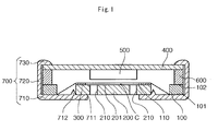
Fig. 1 is a back electret condenser microphone. The electret condenser microphone includes aframe 100 having adiaphragm 110 affixed thereto, abackplate 200, aspacer 300, a printed circuit board (PCB) 400, a field-effect transistor (FET) 500, an electricallyconductive ring 600, and acapsule 700 containing all the other components. Each component of the microphone will be described in detail below. - The
frame 100 is a circular electrically conductive ring. Theframe 100 is set on an electrically isolated portion (not shown) of a bottom plate 710 (to be described below) of thecapsule 700. - The
diaphragm 110 is made of a well-known metal thin film. Thediaphragm 110 is affixed to a lower surface 101 (a first surface) of theframe 100 with conductive adhesive. - The ring 600 (gate ring) is an annular member having substantially the same outer diameter as that of the
frame 100. Thering 600 is disposed on anupper surface 102 of theframe 100 and is interposed between the PCB 400 and theframe 100. - The PCB 400 is a well-known circular circuit board and is disposed above the
frame 100 and thering 600. The PCB 400 has substantially the same outer diameter as that of theframe 100. ThePCB 400 is provided with first and second conductive lines (not shown). The first conductive line contacts thering 600, while connecting to a gate terminal of the FET 500 that is mounted at the center of a lower surface of the PCB 400. The second conductive line contacts a swaged portion 730 (to be described below) of thecapsule 700 for connection with a ground terminal (not shown). - The
spacer 300 is an insulative ring formed on the peripheral edge of an upper surface of thebackplate 200. As described below, thespacer 300 is interposed between thediaphragm 110 and thebackplate 200 so as to define a predetermined space C therebetween. - The
backplate 200 is a circular conductive metal plate. Thebackplate 200 has an outer diameter that is smaller than the inner diameter of theframe 100 and a thickness that is substantially the same as the thickness of theframe 100. On the upper surface (the surface opposing the diaphragm) of thebackplate 200, there is formed anelectret layer 201, which may be a thin film of polymer such as fluorinated ethylene propylene (FEP). - The
backplate 200 is disposed inside theframe 100. In this state, thebackplate 200 presses thediaphragm 110 via thespacer 300 from below (from the first surface side of the frame) by the combined thickness of thebackplate 200 andspacer 300. A space C (capacitor) having the thickness of thespacer 300 is thereby formed between theelectret layer 201 on thebackplate 200 and thediaphragm 110, while tightening thediaphragm 110 to apply tension thereto. - Additionally, the
backplate 200 has a plurality of throughholes 210 penetrating through the thicknesses of thebackplate 200 andelectret layer 201. These columnar throughholes 210 connect a sound receiving aperture 711 (to be described below) in thecapsule 700 with the space C between thebackplate 200 and thediaphragm 110. That is, sound enters thecapsule 700 from thesound receiving aperture 711, past the throughholes 210 and into the space C to cause thediaphragm 110 to vibrate. The vibrations of the diaphragm produce changes in capacitance of the capacitor. - The
capsule 700 is a substantially circular cup-shaped member formed by press-molding a conductive metal plate. Thecapsule 700 includes thebottom plate 710, a cylindricalperipheral wall 720 upstandingly provided on the outer peripheral edge of thebottom plate 710, and aswaged portion 730 provided at the leading end of theperipheral wall 720. - The
bottom plate 710 is provided at its center with thesound receiving aperture 711 in a substantially circular shape. Thebottom plate 710 further has a ring-shaped projection 712 (a positioning means) projecting upward around the periphery of thesound receiving aperture 711. The inner diameter of theprojection 712 is slightly smaller than the outer diameter of thebackplate 200. That is, theprojection 712 is used to hold thebackplate 200 in position on thebottom plate 710, whereby connection is established between thebackplate 200 and the second conductive line of thePCB 400 via thecapsule 700. Along the peripheral edge of thebottom plate 710 there is provided an electrically isolated portion (not shown), on top of which theframe 100 is placed. - The swaged
portion 730 is an inwardly bent piece member. The distance between the lower surface of the swagedportion 730 and an upper surface of thebottom plate 710 is substantially equal to the total thickness of thePCB 400, thering 600 and theframe 100. That is, the stackedframe 100,ring 600, andPCB 400 are held between the swagedportion 730 and thebottom plate 710. - The electret condenser microphone having the above-described structure is assembled in the following steps. First, the
electret layer 201 of thin film is formed over the upper surface of thebackplate 200 using a well-known film-forming method such as spin coating, sputtering, or chemical vapor deposition (CVD). Thespacer 300 is then printed on the outer peripheral edge of theelectret layer 201. - The
backplate 200 is then inserted inside theprojection 712 of thecapsule 700, so that thebackplate 200 is held in position by theprojection 712 and is electrically connected to thecapsule 700. - After that, the
frame 100 with thediaphragm 110 affixed is set on the electrically isolated portion of thebottom plate 710 of thecapsule 700, with thediaphragm 110 facing downward. It should be noted here that thebackplate 200 and thespacer 300 thereon are placed inside theframe 100 from below, and that thediaphragm 110 is pressed from below by thespacer 300 on thebackplate 200. As a result, thediaphragm 110 becomes tightened and gains tension. Simultaneously therewith, the space C is formed between thediaphragm 110 and theelectret layer 201 on thebackplate 200. - After that, the
ring 600 and thePCB 400 with theFET 500 mounted thereon are stacked, in this order, on top of theframe 100. Thering 600 thus comes into contact with the first conductive line of thePCB 400, and thediaphragm 110 on theframe 100 is electrically connected with the gate terminal of theFET 500 by way of thering 600 and the first conductive line of thePCB 400. - After that, the leading end of the
peripheral wall 720 of thecapsule 700 is bent inward. The bent portion becomes the swagedportion 730 to abut on the outer peripheral edge of the upper surface of thePCB 400. As a result, theframe 100, thering 600, and thePCB 400 are held between the swagedportion 730 and thebottom plate 710. Simultaneously therewith, the swagedportion 730 comes into contact with the second conductive line of thePCB 400. Theelectret layer 201 on thebackplate 200 is thus electrically connected to the ground terminal by way of thecapsule 700 and the second conductive line of thePCB 400. - The electret condenser microphone assembled in the above steps allows sound to pass from the
sound receiving aperture 711 of thecapsule 700, through the throughholes 210 and into the space C, thereby making thediaphragm 110 vibrate. The vibrations of thediaphragm 110 produce changes in capacitance of the capacitor. Changes in capacitance are fed as electrical signals to theFET 500, by way of theframe 100, thering 600, and the first conductive line. - In such an electret condenser microphone, the
backplate 200 is disposed inside theframe 100, i.e., substantially level with theframe 100. As such, the microphone may have an advantageously reduced thickness compared with the conventional exemplary microphones. - In addition, the
backplate 200 is set inside theframe 100 and presses thediaphragm 110 affixed to the lower surface of theframe 100 via thespacer 300 from below by the combined thickness of thebackplate 200 andspacer 300. By being pressed by thebackplate 200 and thespacer 300, thediaphragm 110 becomes tightened and favorably gains tension. Consequently, it becomes possible to reduce the distance between thediaphragm 110 and thebackplate 200--i.e., the height of the space C--from a conventional distance of 25-38 µm to around 10 µm, and also possible to improve sensitivity of thediaphragm 110. Increased tension of thediaphragm 110 helps to reduce undesirable variations in tension between diaphragms produced by affixing a film to a plurality of frames. More particularly, in mass production of the microphones, a plurality of frames may be affixed to a single film, which may be cut apart to form a plurality of diaphragms affixed to the respective frames. Although such diaphragms may vary in tension, the invention can reduce the variations because each diaphragm is pressed by the backplate via the spacer. - An electret condenser microphone according to a second embodiment of the present invention is described below with reference to
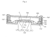
Fig. 2. Fig. 2 is a schematic cross-sectional view of the electret condenser microphone according to the second embodiment of the present invention. - The electret condenser microphone as shown in
Fig. 2 is different from the microphone of the first embodiment in that thebackplate 200 and thespacer 300 are replaced by a backplate portion 741' and a spacer 742' of a protruded portion 740' of a capsule 700'. The differences will be elucidated below, and description of overlapping components, i.e., components common to the first and second embodiments, will not be repeated to avoid redundancy. The reference numerals of the capsule and its subcomponents are distinguished from those of the first embodiment by adding the suffix "'". - The capsule 700' is a substantially circular cup-shaped member formed by press-molding a conductive metal plate. The capsule 700' includes a bottom plate 710', a cylindrical peripheral wall 720' upstandingly provided on the outer peripheral edge of the bottom plate 710', a swaged portion 730' provided at the leading end of the peripheral wall 720', and the upwardly protruded portion 740' formed at a central portion of the bottom plate 710' by pressing, for example by performing press drawing.
- The protruded portion 740' includes the backplate portion 741' in a substantially circular pedestal-like shape, and the spacer 742' protruded from the outer peripheral edge of a top plate (to be described below) of the backplate portion 741'.
- The spacer 742' is a ring-shaped protrusion and its upper surface for contacting
diaphragm 110 is electrically isolated. - The backplate portion 741' has an upstanding cylindrical portion and the top plate closes an upper opening of the cylindrical portion. The portion other than the outer peripheral edge of the top plate has an electret layer 743', which may be a thin film of polymer such as FEP.
- The backplate portion 741' is set inside a
frame 100. In this state, the backplate portion 741' presses thediaphragm 110 via the spacer 742' from below (from the first surface side of the frame) by the combined thickness of the backplate portion 741' and spacer 742'. Space C (capacitor) having the thickness of the spacer 742' is thereby formed between the electret layer 743' on the backplate portion 741' and thediaphragm 110, while tightening thediaphragm 110 to apply tension. - The top plate of the backplate portion 741' is provided with a plurality of through
holes 741a' penetrating through the top plate and the electret layer 743'. The columnar throughholes 741a' serve as sound receiving apertures, which connect the outside of the capsule 700' with the space C between the backplate portion 741' and thediaphragm 110. The throughholes 741a' allow sound to enter therethrough into the space C to make thediaphragm 110 vibrate. The vibrations of thediaphragm 110 produce changes in capacitance of the capacitor. - The electret condenser microphone configured as above is assembled in the following steps. First, the
frame 100 affixed with thediaphragm 110 is set on an electrically isolated portion of the bottom plate 710' of the capsule 700' with thediaphragm 110 facing downward. It should be noted here that the backplate portion 741' and the spacer 742' thereon are placed inside theframe 100 from below, and that thediaphragm 110 is pressed from below by the spacer 742' on the backplate portion 741'. As a result, thediaphragm 110 becomes tightened and gains tension. Simultaneously therewith, the space C is formed between thediaphragm 110 and the electret layer 743' on the backplate portion 741'. - After that, a
ring 600 and aPCB 400 with anFET 500 mounted thereon are stacked, in this order, on top of theframe 100. Thering 600 thus contacts a first conductive line of thePCB 400, and thediaphragm 110 on theframe 100 is electrically connected with a gate terminal of theFET 500 by way of thering 600 and the first conductive line of thePCB 400. - After that, the leading end of the peripheral wall 720' of the capsule 700' is bent inward. The bent portion becomes the swaged portion 730' to abut on the outer peripheral edge of an upper surface of the
PCB 400. As a result, theframe 100, thering 600, and thePCB 400 are held between the swaged portion 730' and the bottom plate 710'. Simultaneously therewith, the swaged portion 730' comes into contact with a second conductive line of thePCB 400. The electret layer 743' on the backplate portion 741' is thus electrically connected with a ground terminal via the capsule 700' and the second conductive line of thePCB 400. - The electret condenser microphone assembled in the above steps allows sound to pass from the through
holes 741a' in the capsule 700' into the space C, thereby making thediaphragm 110 vibrate. The vibrations of thediaphragm 110 produce changes in capacitance of the capacitor. Changes in the capacitance are fed as electrical signals to theFET 500, by way of theframe 100, thering 600, and the first conductive line. - In such an electret condenser microphone, the backplate portion 741' is disposed inside the
frame 100, i.e., substantially level with theframe 100. The microphone may have an advantageously reduced thickness compared with the conventional exemplary microphones. - In addition, the backplate portion 741' is set inside the
frame 100 and presses thediaphragm 110 affixed to thelower surface 101 of theframe 100 from below via the spacer 742' by the combined thickness of the backplate portion 741' and spacer 742'. By being pressed by the backplate portion 741' and the spacer 742', thediaphragm 110 is tightened and favorably gains tension. Consequently, it becomes possible to reduce the distance between thediaphragm 110 and the backplate portion 741'--i.e., the height of the space C--from the conventional distance of 25-38 µm to around 10 µm, and also possible to improve sensitivity of thediaphragm 110. Increased tension of thediaphragm 110 helps to reduce undesirable variations in tension between diaphragms produced by affixing a film to a plurality of frames. More particularly, in mass production of the microphones, a plurality of frames may be affixed to a single film, which may be cut or otherwise divided to form a plurality of diaphragms affixed to the respective frames. Although such diaphragms may vary in tension, the invention can reduce the variations because each diaphragm is pressed by the backplate via the spacer. - Another advantageous feature of the second embodiment is that a portion of the capsule 700' (the protruded portion 740') forms the backplate portion 741' and the spacer 742'. The microphone makes it possible to reduce the number of components and assembly man-hours, in comparison with providing the backplate portion 741' and the spacer 742' as discrete components. Consequently, the microphone is advantageous in cost reduction.
- The above-described electret condenser microphones may be appropriately modified in design as described below, without departing from the scope of the present invention as set forth in the claims.
-
Fig. 3 illustrates a modified electret condenser microphone of the first embodiment of the present invention in a schematic cross-sectional view. - The
backplate 200 as disposed inside aframe 100 may or may not press adiaphragm 110. For example, thebackplate 200 disposed inside aframe 100 may be placed to face thediaphragm 110 affixed to an upper surface of theframe 100 with a predetermined space provided between the diaphragm and the backplate. This arrangement may be applied to the backplate portion 741'. In this case, aspacer 300 or 742' may or may not be provided in order to form the space. - The
spacer 300 of the present invention is not limited to a ring-shaped one. For example, a plurality ofspacers 300 may be arranged annularly on thebackplate 200. - The spacer 742' is not limited to the above-described one formed by means of press drawing along the outer peripheral edge of the top plate of the backplate portion 741'. For example, as in the case of the
spacer 300, the spacer 742' may be formed by printing an insulative layer on the outer peripheral edge of the top plate of the backplate portion 741'. In this case, a plurality of spacers may be arranged annularly on the backplate portion 741' as described above. - The protruded portion 740' of the second embodiment is made by performing press drawing on the central portion of the bottom plate 710' of the capsule 700'; however, the present invention is not limited thereto. For example, if the capsule 700' is a resin molded article as is described later, the protruded portion may be formed in the course of resin molding of the capsule 700'. In this case, a plurality of spacers may be formed annularly on the backplate portion.
- The
diaphragm 110 of either embodiment is provided on the lower surface of theframe 100. However, the diaphragm may be given appropriate pressure even if it is provided on the upper surface of the frame. More particularly, thediaphragm 110 of the first embodiment can be pressed if the combined thickness of thebackplate 200 and thespacer 300 disposed inside theframe 100 is larger than the thickness of theframe 100. Similarly, thediaphragm 110 of the second embodiment can be pressed if the combined thickness of the backplate portion 741' and the spacer 742' disposed inside the frame 100 (i.e., the height of the protruded portion 740') is larger than the thickness of theframe 100. - The
board 400 may be disposed above theframe 100 as in the above embodiments but may also be disposed below theframe 100. The latter case is exemplified in a modified microphone as shown inFig. 3 , wherein aninsulative ring 800 is interposed between thePCB 400 and theframe 100 so as to establish connection between theframe 100 and the second conductive line of thePCB 400 through the capsule 700''. Meanwhile, thePCB 400 is provided thereon with a ring-shaped conductive retainingportion 900 for retaining thebackplate 200 so as to establish connection between thebackplate 200 and the first conductive line of thePCB 400 through theconductive retaining portion 900. It should be noted that thebottom plate 710" of the capsule 700'' has a plurality of sound receiving apertures 711''. The modified microphone may have similar advantageous effects to the preferred first embodiment because thebackplate 200 of the modification is also disposed inside theframe 100 and presses thediaphragm 110. - The
capsule backplate 200 and thePCB 400, or between the electret layer 743' on the backplate portion 741' and thePCB 400. As described above, theframe 100 and thePCB 400 may be connected via the conductive lines of the capsule. - The
bottom plate 710 of the invention is not limited to the above-described one having theprojection 712 as a positioning means for thebackplate 200. That is, any type of positioning means may be adopted insofar as the means can position and hold thebackplate 200. For example, thebottom plate 710 may be provided with a recess to fittingly receive thebackplate 200. - The electret condenser microphones according to the foregoing embodiments are back electret condenser microphones in which the electret layer is provided on the surface of the
backplate 200 or 741' opposite the diaphragm. However, the invention may be applied to a foil electret condenser microphone, in which thediaphragm 110 itself is made of a polymer film for use as electret. - Any modifications or changes may be made to the above-described components in shape, material and number as long as they can carry out similar functions to ones described above. Obviously, the components need not necessarily take circular (i.e., round) shapes as described above but may take polygonal (i.e., angular) shapes.
-
- 100
- Frame
- 110
- Diaphragm
- 200
- Backplate
- 300
- Spacer
- 700
- Capsule
- 712
- Projection (Positioning means)
- 700'
- Capsule
- 740'
- Protruded portion
- 741'
- Backplate portion
- 742'
- Spacer
Claims (7)
- An electret condenser microphone comprising:a diaphragm (110);a frame (100), adapted for affixing the diaphragm thereto; anda backplate (200, 741'), positionable inside the frame and opposite the diaphragm with a space (C) defined therebetween, said backplate having a through-hole (210, 741a') communicating with the space.
- The electret condenser microphone according to claim 1, further comprising a spacer (300), the spacer being provided at a surface of the backplate (200) opposite the diaphragm (110), to define the space (C) between the backplate (200) and the diaphragm,
wherein the backplate as disposed inside the frame (100) is adapted to press the diaphragm via the spacer. - The electret condenser microphone according to claim 2, wherein
the diaphragm (110) is affixed to a first surface (101) of the frame (100), and
the backplate (200) is adapted to press the diaphragm via the spacer (300) from the first surface side of the frame. - The electret condenser microphone according to any one of claims 1, 2, and 3, further comprising a capsule (700) for accommodating the frame (100), the capsule including a protruded portion (740') adapted to be disposed inside the frame, the protruded portion functioning as the backplate (200).
- The electret condenser microphone according to claim 1, further comprising a capsule (700) for accommodating the frame (100) and the backplate (200), the capsule including positioning means (712) for positioning and holding the backplate.
- The electret condenser microphone according to claim 2 or 3, further comprising a capsule (700) for accommodating the frame (100), the spacer (300) and the backplate (200), the capsule including positioning means (712), wherein the backplate as held by the positioning means is adapted to press the diaphragm (110).
- The electret condenser microphone according to any preceding claim, further comprising an FET (500) mounted on a PCB (400) wherein the diaphragm (110) is electrically connected with a gate terminal of the FET and electret layer (201) is electrically connected to ground.
Applications Claiming Priority (1)
| Application Number | Priority Date | Filing Date | Title |
|---|---|---|---|
| JP2008115255A JP4960921B2 (en) | 2008-04-25 | 2008-04-25 | Electret condenser microphone |
Publications (2)
| Publication Number | Publication Date |
|---|---|
| EP2112840A2 true EP2112840A2 (en) | 2009-10-28 |
| EP2112840A3 EP2112840A3 (en) | 2012-08-29 |
Family
ID=40902795
Family Applications (1)
| Application Number | Title | Priority Date | Filing Date |
|---|---|---|---|
| EP09251174A Ceased EP2112840A3 (en) | 2008-04-25 | 2009-04-24 | Electret condenser microphone |
Country Status (5)
| Country | Link |
|---|---|
| US (1) | US8238587B2 (en) |
| EP (1) | EP2112840A3 (en) |
| JP (1) | JP4960921B2 (en) |
| CN (1) | CN101568056B (en) |
| TW (1) | TWI401974B (en) |
Cited By (1)
| Publication number | Priority date | Publication date | Assignee | Title |
|---|---|---|---|---|
| CN102075838A (en) * | 2011-03-03 | 2011-05-25 | 深圳市豪恩声学股份有限公司 | Electret microphone |
Families Citing this family (6)
| Publication number | Priority date | Publication date | Assignee | Title |
|---|---|---|---|---|
| CN102111704B (en) * | 2009-12-24 | 2013-06-05 | 谢小明 | Capacitance type microphone |
| US8842858B2 (en) | 2012-06-21 | 2014-09-23 | Invensense, Inc. | Electret condenser microphone |
| US20140037120A1 (en) * | 2012-08-01 | 2014-02-06 | Knowles Electronics, Llc | Microphone Assembly |
| PL3373597T3 (en) * | 2017-03-07 | 2020-02-28 | G.R.A.S. Sound & Vibration A/S | Low profile surface mount microphone |
| CN108966100B (en) * | 2018-06-25 | 2020-02-21 | 歌尔股份有限公司 | MEMS microphone |
| US11671763B2 (en) * | 2021-02-24 | 2023-06-06 | Shure Acquisition Holdings, Inc. | Parylene electret condenser microphone backplate |
Citations (2)
| Publication number | Priority date | Publication date | Assignee | Title |
|---|---|---|---|---|
| JP2000050393A (en) | 1998-05-25 | 2000-02-18 | Hosiden Corp | Electret condenser microphone |
| JP2004222091A (en) | 2003-01-16 | 2004-08-05 | Citizen Electronics Co Ltd | Electret condenser microphone |
Family Cites Families (15)
| Publication number | Priority date | Publication date | Assignee | Title |
|---|---|---|---|---|
| US3963881A (en) * | 1973-05-29 | 1976-06-15 | Thermo Electron Corporation | Unidirectional condenser microphone |
| JPS5219569B2 (en) | 1973-09-20 | 1977-05-28 | ||
| JPS5063026U (en) * | 1973-10-09 | 1975-06-09 | ||
| JPS58207798A (en) * | 1982-05-28 | 1983-12-03 | Toshiba Corp | Transducer |
| JPS58209299A (en) * | 1982-05-29 | 1983-12-06 | Toshiba Corp | Transducer |
| JPS59105800A (en) * | 1982-12-08 | 1984-06-19 | Matsushita Electric Ind Co Ltd | Electrostatic speaker |
| CA2315417A1 (en) * | 1999-08-11 | 2001-02-11 | Hiroshi Une | Electret capacitor microphone |
| US6654473B2 (en) * | 2001-05-09 | 2003-11-25 | Knowles Electronics, Llc | Condenser microphone |
| KR200330089Y1 (en) * | 2003-07-29 | 2003-10-11 | 주식회사 비에스이 | Integrated base and electret condenser microphone using the same |
| US7136500B2 (en) * | 2003-08-05 | 2006-11-14 | Knowles Electronics, Llc. | Electret condenser microphone |
| JP4156649B2 (en) * | 2004-04-27 | 2008-09-24 | ホシデン株式会社 | Electret condenser microphone |
| JP2006166078A (en) * | 2004-12-08 | 2006-06-22 | Audio Technica Corp | Condenser microphone unit and condenser microphone |
| KR100675024B1 (en) * | 2005-06-13 | 2007-01-30 | 주식회사 비에스이 | Conductive Base of Condenser Microphone and Condenser Microphone Using the Same |
| US20070003081A1 (en) * | 2005-06-30 | 2007-01-04 | Insound Medical, Inc. | Moisture resistant microphone |
| JP2007129543A (en) * | 2005-11-04 | 2007-05-24 | Hosiden Corp | Electret condenser microphone |
-
2008
- 2008-04-25 JP JP2008115255A patent/JP4960921B2/en not_active Expired - Fee Related
-
2009
- 2009-03-13 TW TW098108267A patent/TWI401974B/en not_active IP Right Cessation
- 2009-03-20 US US12/408,156 patent/US8238587B2/en not_active Expired - Fee Related
- 2009-04-22 CN CN200910135060.3A patent/CN101568056B/en not_active Expired - Fee Related
- 2009-04-24 EP EP09251174A patent/EP2112840A3/en not_active Ceased
Patent Citations (2)
| Publication number | Priority date | Publication date | Assignee | Title |
|---|---|---|---|---|
| JP2000050393A (en) | 1998-05-25 | 2000-02-18 | Hosiden Corp | Electret condenser microphone |
| JP2004222091A (en) | 2003-01-16 | 2004-08-05 | Citizen Electronics Co Ltd | Electret condenser microphone |
Cited By (2)
| Publication number | Priority date | Publication date | Assignee | Title |
|---|---|---|---|---|
| CN102075838A (en) * | 2011-03-03 | 2011-05-25 | 深圳市豪恩声学股份有限公司 | Electret microphone |
| CN102075838B (en) * | 2011-03-03 | 2013-12-18 | 深圳市豪恩声学股份有限公司 | Electret microphone |
Also Published As
| Publication number | Publication date |
|---|---|
| US8238587B2 (en) | 2012-08-07 |
| JP4960921B2 (en) | 2012-06-27 |
| TW200945915A (en) | 2009-11-01 |
| US20090268930A1 (en) | 2009-10-29 |
| JP2009267782A (en) | 2009-11-12 |
| TWI401974B (en) | 2013-07-11 |
| CN101568056B (en) | 2015-04-01 |
| EP2112840A3 (en) | 2012-08-29 |
| CN101568056A (en) | 2009-10-28 |
Similar Documents
| Publication | Publication Date | Title |
|---|---|---|
| EP2112840A2 (en) | Electret condenser microphone | |
| US8331589B2 (en) | MEMS microphone | |
| US8379881B2 (en) | Silicon based capacitive microphone | |
| US20100322443A1 (en) | Mems microphone | |
| US20060143911A1 (en) | Electret condenser microphone and method of producing same | |
| EP3435685B1 (en) | Diaphragm and manufacturing method for diaphragm | |
| KR200218653Y1 (en) | An electret condenser microphone | |
| CN108464017B (en) | Microphone and method for manufacturing microphone | |
| US6512833B2 (en) | Electret condenser microphone and method of producing same | |
| US7184563B2 (en) | Electret condenser microphone | |
| CN102868960A (en) | Welding type condenser microphone using curling and method of assemblying the same | |
| US6678383B2 (en) | Capacitor microphone | |
| US7346182B2 (en) | Electroacoustic transducer and method for manufacturing the same | |
| JP2004032019A (en) | Capacitor microphone | |
| KR100543784B1 (en) | Backplate for electret condenser microphone, method of making the same and the microphone using the same | |
| JP4014886B2 (en) | Condenser microphone | |
| KR100696164B1 (en) | Holder of Back Plate And Condensor MicroPhone Including the same And Assembly Method thereof | |
| KR20090113210A (en) | Electret condenser microphone | |
| JPH0523698U (en) | Electret condenser microphone unit | |
| JP2006033215A (en) | Condenser microphone and manufacturing method thereof | |
| KR200216310Y1 (en) | Condensor microphone | |
| KR20050037817A (en) | Case making a stair and electret condenser microphone using the same | |
| JP4362419B2 (en) | Condenser microphone | |
| KR20040080542A (en) | Eletret condenser microphone framing | |
| KR100508377B1 (en) | Electret Condenser Microphone and Assemble Method thereof |
Legal Events
| Date | Code | Title | Description |
|---|---|---|---|
| PUAI | Public reference made under article 153(3) epc to a published international application that has entered the european phase |
Free format text: ORIGINAL CODE: 0009012 |
|
| AK | Designated contracting states |
Kind code of ref document: A2 Designated state(s): AT BE BG CH CY CZ DE DK EE ES FI FR GB GR HR HU IE IS IT LI LT LU LV MC MK MT NL NO PL PT RO SE SI SK TR |
|
| PUAL | Search report despatched |
Free format text: ORIGINAL CODE: 0009013 |
|
| AK | Designated contracting states |
Kind code of ref document: A3 Designated state(s): AT BE BG CH CY CZ DE DK EE ES FI FR GB GR HR HU IE IS IT LI LT LU LV MC MK MT NL NO PL PT RO SE SI SK TR |
|
| AX | Request for extension of the european patent |
Extension state: AL BA RS |
|
| RIC1 | Information provided on ipc code assigned before grant |
Ipc: H04R 19/01 20060101AFI20120724BHEP |
|
| 17P | Request for examination filed |
Effective date: 20121217 |
|
| 17Q | First examination report despatched |
Effective date: 20130128 |
|
| STAA | Information on the status of an ep patent application or granted ep patent |
Free format text: STATUS: THE APPLICATION HAS BEEN REFUSED |
|
| 18R | Application refused |
Effective date: 20140406 |