JP4960921B2 - Electret condenser microphone - Google Patents
Electret condenser microphone Download PDFInfo
- Publication number
- JP4960921B2 JP4960921B2 JP2008115255A JP2008115255A JP4960921B2 JP 4960921 B2 JP4960921 B2 JP 4960921B2 JP 2008115255 A JP2008115255 A JP 2008115255A JP 2008115255 A JP2008115255 A JP 2008115255A JP 4960921 B2 JP4960921 B2 JP 4960921B2
- Authority
- JP
- Japan
- Prior art keywords
- back electrode
- frame
- condenser microphone
- capsule
- electret condenser
- Prior art date
- Legal status (The legal status is an assumption and is not a legal conclusion. Google has not performed a legal analysis and makes no representation as to the accuracy of the status listed.)
- Expired - Fee Related
Links
Images
Classifications
-
- H—ELECTRICITY
- H04—ELECTRIC COMMUNICATION TECHNIQUE
- H04R—LOUDSPEAKERS, MICROPHONES, GRAMOPHONE PICK-UPS OR LIKE ACOUSTIC ELECTROMECHANICAL TRANSDUCERS; DEAF-AID SETS; PUBLIC ADDRESS SYSTEMS
- H04R19/00—Electrostatic transducers
- H04R19/01—Electrostatic transducers characterised by the use of electrets
- H04R19/016—Electrostatic transducers characterised by the use of electrets for microphones
Landscapes
- Physics & Mathematics (AREA)
- Engineering & Computer Science (AREA)
- Acoustics & Sound (AREA)
- Signal Processing (AREA)
- Electrostatic, Electromagnetic, Magneto- Strictive, And Variable-Resistance Transducers (AREA)
Description
本発明はエレクトレットコンデンサマイクロホンに関する。 The present invention relates to an electret condenser microphone.
この種のエレクトレットコンデンサマイクロホンは、振動膜が貼付された枠体と、振動膜と所定の空間を空けて略平行に配置される背極板とを備えている(特許文献1及び2参照)。 This type of electret condenser microphone includes a frame body to which a diaphragm is attached, and a back electrode plate that is disposed substantially in parallel with the diaphragm in a predetermined space (see Patent Documents 1 and 2).
ところが、枠体と背極板とは、その外径が略同じであって、垂直に並べて配置される。この点で、エレクトレットコンデンサマイクロホンの厚みの低減が妨げられていた。 However, the frame body and the back electrode plate have substantially the same outer diameter and are arranged side by side vertically. In this respect, reduction of the thickness of the electret condenser microphone has been hindered.
本発明は、上記事情に鑑みて創案されたものであって、その目的とするところは、枠体と背極板とを略同一高さに配置し、厚みを低減することができるエレクトレットコンデンサマイクロホンを提供することにある。 The present invention has been made in view of the above circumstances, and an object of the present invention is to provide an electret condenser microphone in which the frame body and the back electrode plate are arranged at substantially the same height and the thickness can be reduced. Is to provide.
上記課題を解決するために、本発明の第1エレクトレットコンデンサマイクロホンは、上面と下面とを有する枠体と、前記枠体の下面に貼付された振動膜と、前記枠体内に配置されており且つ上面と下面とを有する背極と、前記背極の上面に設けられ且つ絶縁性を有するスペーサとを備えている。前記枠体の下面と前記背極の下面とが同一高さに配置され、前記背極の上面が前記枠体の下面よりも上側に位置し、前記スペーサが当該スペーサの高さ寸法と前記背極の高さ寸法との和の分、前記振動膜を押圧し、前記背極が前記振動膜に所定の空間を有して対向している。 In order to solve the above-mentioned problem, a first electret condenser microphone of the present invention includes a frame having an upper surface and a lower surface, a vibration film attached to the lower surface of the frame, and disposed in the frame. A back electrode having an upper surface and a lower surface; and a spacer provided on the upper surface of the back electrode and having an insulating property. The lower surface of the frame body and the lower surface of the back electrode are disposed at the same height, the upper surface of the back electrode is positioned above the lower surface of the frame body, and the spacer has a height dimension of the spacer and the back surface of the frame. The vibrating membrane is pressed by the sum of the height of the poles, and the back electrode is opposed to the vibrating membrane with a predetermined space.
このような発明の態様による場合、背極が枠体内に配置されている。即ち、枠体と背極とが略同一高さに配置されているので、従来例に比べて、本マイクロホンの厚みを低減することができる。
また、背極がスペーサを介して振動膜を押圧することにより、振動膜が緊張し、その張力が向上する。このため、振動膜と背極との間の空間を小さくすることができ、振動膜の感度を向上させることができる。また、振動膜の張力の向上により、複数の枠体に一枚のフィルムを同時に貼付することにより作成される各振動膜に生じる張力のバラツキが低減される。
また、背極及びスペーサを枠体内に配置するだけで、当該背極及びスペーサの厚み分(両者の高さ寸法の和の分)、振動膜が押圧されるので、振動膜の張力の一層向上を図ることができる。
According to such an aspect of the invention , the back electrode is disposed in the frame. That is, since the frame body and the back pole are disposed at substantially the same height, the thickness of the present microphone can be reduced as compared with the conventional example.
Further, when the back electrode presses the vibration film via the spacer, the vibration film is tensioned and the tension is improved. For this reason, the space between the diaphragm and the back electrode can be reduced, and the sensitivity of the diaphragm can be improved. In addition, by improving the tension of the vibration film, variation in tension generated in each vibration film created by applying a single film to a plurality of frames at the same time is reduced.
In addition, simply placing the back electrode and spacer in the frame allows the diaphragm to be pressed by the thickness of the back electrode and spacer (the sum of their height dimensions), further improving the tension of the diaphragm. Can be achieved.
前記第1エレクトレットコンデンサマイクロホンは、前記枠体の下面と前記背極の下面とが設置された設置部を更に備えた構成とすることが可能である。The first electret condenser microphone may further include an installation portion in which the lower surface of the frame body and the lower surface of the back electrode are installed.
前記第1エレクトレットコンデンサマイクロホンは、前記枠体及び背極を収容するカプセルを更に備えた構成とすることが可能である。前記カプセルは、前記設置部と、前記設置部に設けられ、前記背極を位置決め保持する位置決め手段とを有する構成とすることが可能である。このような発明の態様による場合、位置決め手段により背極をカプセル内で簡単に位置決め保持することができるので、背極の取り付けが簡単になる。The first electret condenser microphone may further include a capsule that houses the frame body and the back electrode. The capsule may have a configuration including the installation portion and positioning means provided in the installation portion and positioning and holding the back pole. According to such an aspect of the invention, the back electrode can be easily positioned and held in the capsule by the positioning means, so that the back electrode can be easily attached.
第1エレクトレットコンデンサマイクロホンは、前記枠体の上面に設置されたゲートリングと、前記ゲートリング上に設置されており且つ前記ゲートリングに接触した第1導電パターンと、第2導電パターンを有する基板と、前記基板上に実装され、前記第1導電パターンに接続されたFETと、導電性を有し且つ前記枠体及び背極を収容するカプセルとを更に備えた構成とすることが可能である。前記カプセルは、前記設置部と、前記設置部の外周縁部に立設された周壁部と、前記周壁部の先端部に設けられ、前記基板に当接し、前記第2導電パターンに接触するカシメ部とを更に有する構成とすることが可能である。The first electret condenser microphone includes a gate ring installed on an upper surface of the frame, a first conductive pattern disposed on the gate ring and in contact with the gate ring, and a substrate having a second conductive pattern. It is possible to further comprise a FET mounted on the substrate and connected to the first conductive pattern, and a capsule having conductivity and accommodating the frame body and the back electrode. The capsule is provided at the installation portion, a peripheral wall portion erected on an outer peripheral edge of the installation portion, and a distal end portion of the peripheral wall portion, and is in contact with the substrate and is in contact with the second conductive pattern. It is possible to make it the structure which further has a part.
本発明の第2エレクトレットコンデンサマイクロホンは、上面と下面とを有する枠体と、前記枠体の下面に貼付された振動膜と、導電性を有するカプセルとを備えている。前記カプセルは、前記枠体内に挿入された突起部を有している。前記突起部は、背極と、前記背極に設けられたスペーサとを有している。前記枠体の下面が前記カプセルの突起部周りに当接し、前記スペーサが当該スペーサの高さ寸法と前記背極の高さ寸法との和の分、前記振動膜を押圧し、前記背極が前記振動膜に所定の空間を有して対向している。The second electret condenser microphone of the present invention includes a frame having an upper surface and a lower surface, a vibration film attached to the lower surface of the frame, and a conductive capsule. The capsule has a protrusion inserted into the frame. The protrusion has a back electrode and a spacer provided on the back electrode. The lower surface of the frame body abuts around the protrusion of the capsule, the spacer presses the vibrating membrane by the sum of the height dimension of the spacer and the height dimension of the back electrode, and the back electrode It faces the vibration film with a predetermined space.
このような発明の態様による場合、カプセルの突起部が背極を有していることから、背極が別体である場合と比べて、部品点数及び組み立て工数の低減を図ることができる。その結果、低コスト化を図ることができる。 According to such an aspect of the invention, since the protruding portion of the capsule has the back pole, the number of parts and the number of assembly steps can be reduced as compared with the case where the back pole is a separate body. As a result, cost reduction can be achieved.
第2エレクトレットコンデンサマイクロホンは、前記枠体の上面に設置されたゲートリングと、前記ゲートリング上に設置されており且つ前記ゲートリングに接触した第1導電パターンと、第2導電パターンを有する基板と、前記基板上に実装され、前記第1導電パターンに接続されたFETとを更に備えた構成とすることが可能である。前記カプセルは、前記突起部を有する底板部と、前記底板部の外周縁部に立設された周壁部と、前記周壁部の先端部に設けられ、前記基板に当接し、前記第2導電パターンに接触するカシメ部とを更に有する構成とすることが可能である。The second electret condenser microphone includes a gate ring installed on an upper surface of the frame, a first conductive pattern disposed on the gate ring and in contact with the gate ring, and a substrate having a second conductive pattern. And a FET mounted on the substrate and connected to the first conductive pattern. The capsule is provided at a bottom plate portion having the protrusion, a peripheral wall portion standing on an outer peripheral edge portion of the bottom plate portion, and a front end portion of the peripheral wall portion, abutting on the substrate, and the second conductive pattern It is possible to make it the structure which has further the crimping | crimped part which contacts.
以下、本発明の実施例について説明する。 Examples of the present invention will be described below.
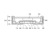
まず、本発明の実施例1に係るエレクトレットコンデンサマイクロホンについて図1を参照しつつ説明する。図1は本発明の実施例1に係るエレクトレットコンデンサマイクロホンの模式的断面図である。 First, an electret condenser microphone according to Embodiment 1 of the present invention will be described with reference to FIG. FIG. 1 is a schematic cross-sectional view of an electret condenser microphone according to Embodiment 1 of the present invention.
図1に示すエレクトレットコンデンサマイクロホンは、バックエレクトレットコンデンサマイクロホンであって、振動膜110が貼付された枠体100と、この枠体100内に配置される背極板200と、振動膜110と背極板200との間に所定の空間Cを確保するスペーサ300と、枠体100の上方に配置される基板400と、この基板400の下面中央部に実装されたFET(電界効果トランジスタ)500と、基板400と枠体100との間に介在するゲートリング600と、これらを収容するカプセル700とを備えている。以下、各部について詳しく説明する。
The electret condenser microphone shown in FIG. 1 is a back electret condenser microphone, and includes a
枠体100は円形の導電リングである。この枠体100はカプセル700の底板部710の図示しない絶縁処理部上に設置される。
The
振動膜110は周知の金属薄膜である。この振動膜110は導電性接着剤により枠体100の下面(第1面)に接着される。
The
ゲートリング600は外径が枠体100の外径と略同じ円形の環状体である。このゲートリング600が枠体100の上面に設置される。
The
基板400は周知の円形の回路基板であって、その外径が枠体100の外径と略同じになっている。この基板400には図示しない第1、第2の導電パターンが設けられている。この第1の導電パターンはゲートリング600に接触し且つFET500のゲート端子に接続される。第2の導電パターンはカシメ部730に接触し、図示しないグランド端子に接続される。
The
スペーサ300は背極板200の上面の周縁部に形成された絶縁リングである。
The
背極板200は導電性を有する円形の金属板である。背極板200は、外径が枠体100の内径よりも小さく、厚みが枠体100の厚みと略同じになっている。背極板200の上面(振動膜対向面)には高分子フィルム(例えば、FEP)等の薄膜である図示しないエレクトレット層が形成されている。なお、背極板200の下面は、背極板200の上面の反対側の面である。
The
この背極板200は下方(枠体の第1面側)から枠体100内に配置されている。この状態で、背極板200は、スペーサ300を介して振動膜110を当該背極板200及びスペーサ300の厚み分押圧する。これにより、背極板200のエレクトレット層と振動膜110との間にスペーサ300の厚み分の空間C(コンデンサ)が形成されると共に、振動膜110が緊張し、その張力が向上する。
The
また、背極板200には、当該背極板200及び前記エレクトレット層を厚み方向に貫通する複数の貫通孔210が設けられている。この貫通孔210はカプセル700の音孔711と、背極板200と振動膜110との間の空間Cとを繋ぐ円柱状の孔である。即ち、音孔711からカプセル700内に入った音声が、貫通孔210を通じて空間Cに入り込み、振動膜110を振動させる。これにより、前記コンデンサの静電容量が変化する。
The
カプセル700は、導電金属板をプレス成型することにより作成された略円形のカップ体であって、底板部710(設置部)と、底板部710の外周縁部に立設された円筒状の周壁部720と、周壁部720の先端部に設けられたカシメ部730とを有している。
The
底板部710の中央部には略円形の音孔711が開設されている。また、底板部710の音孔711の周縁部上にはリング状の突脈712(位置決め手段)が凸設されている。この突脈712の内径は背極板200の外径よりも若干小さくなっている。即ち、突脈712が背極板200を底板部710上で位置決め保持する。これにより、背極板200がカプセル700を介して基板400の第2の導電パターンに接続される。なお、底板部710の外周縁部の内面上には図示しない絶縁処理部が形成されている。
A substantially
カシメ部730は内側に折り曲げられた片部材である。このカシメ部730の下面と底板部710の上面との間の距離が基板400、ゲートリング600及び枠体100の厚みの和と略同じになっている。即ち、カシメ部730と底板部710との間で、積層された枠体100、ゲートリング600及び基板400が挟持されるようになっている。
The
以上のような構成のエレクトレットコンデンサマイクロホンは次のように組み立てられる。まず、背極板200の上面にスピンナー・コート、スパッタリング、CVD等の周知の成膜方法により、エレクトレット層の薄膜を形成する。そして、前記エレクトレット層の外周縁部上にスペーサ300を印刷により形成する。
The electret condenser microphone configured as described above is assembled as follows. First, a thin film of an electret layer is formed on the upper surface of the
この背極板200をカプセル700の突脈712内に挿入する。これにより背極板200が突脈712に位置決め保持されると共に、カプセル700に電気的に接続される。
The
その後、振動膜110が貼付された枠体100を、振動膜110を下方に向けた状態で、カプセル700の底板部710の絶縁処理部上に設置する。すると、振動膜110が背極板200上のスペーサ300により下方から押圧される。これにより、振動膜110が緊張し、その張力が向上する。これと共に、振動膜110と背極板200上のエレクトレット層との間に空間Cが形成される。
Thereafter, the
その後、枠体100上にゲートリング600及びFET500が実装された基板400を順次積層する。これにより、ゲートリング600が基板400の第1の導電パターンに接触し、枠体100の振動膜110がゲートリング600及び基板400の第1の導電パターンを介してFET500のゲート端子に電気的に接続される。
Thereafter, the
その後、カプセル700の周壁部720の先端部を内側に折り曲げる。この折り曲げ部がカシメ部730となり、基板400の上面の外周縁部に当接する。これにより、カシメ部730と底板部710との間で枠体100、ゲートリング600及び基板400が挟持される。これと共に、カシメ部730が基板400の第2の導電パターンに接触する。これにより、背極板200のエレクトレット層がカプセル700及び基板400の第2の導電パターンを介してグランド端子に電気的に接続される。
Then, the front-end | tip part of the surrounding
このようにして組み立てられたエレクトレットコンデンサマイクロホンは、カプセル700の音孔711及び貫通孔210を通じて音声が空間Cに入り込み、振動膜110を振動させる。この振動膜110の振動により上記コンデンサの静電容量が変化する。この静電容量の変化が電気信号として枠体100、ゲートリング600及び第1の導電パターンを介してFET500に入力される。
In the electret condenser microphone assembled in this way, sound enters the space C through the
このようなエレクトレットコンデンサマイクロホンによる場合、背極板200が枠体100内に配置されている。即ち、枠体100と背極板200とが略同一高さに配置されているので、従来例に比べて、本マイクロホンの厚みを低減することができる。
In the case of such an electret condenser microphone, the
しかも、背極板200が、枠体100内に下方から配置され、スペーサ300を介して枠体100の下面に貼付された振動膜110を背極板200及びスペーサ300の厚み分押圧するようになっている。この背極板200及びスペーサ300の押圧により、振動膜110が緊張し、その張力が向上するので、振動膜110と背極板200との間の距離(即ち、空間Cの高さ)を従来の25〜38μmから10μm前後まで小さくすることが可能になり、振動膜110の感度を向上させることができる。また、振動膜110の張力の向上により、複数の枠体に一枚のフィルムを同時に貼付することにより作成される各振動膜に生じる張力のバラツキを低減することも可能である。
In addition, the
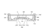
次に、本発明の実施例2に係るエレクトレットコンデンサマイクロホンについて図2を参照しつつ説明する。図2は本発明の実施例2に係るエレクトレットコンデンサマイクロホンの模式的断面図である。 Next, an electret condenser microphone according to Embodiment 2 of the present invention will be described with reference to FIG. FIG. 2 is a schematic cross-sectional view of an electret condenser microphone according to Embodiment 2 of the present invention.
図2に示すエレクトレットコンデンサマイクロホンは、背極板200及びスペーサ300の代わりとしてカプセル700’の突起部740’の背極741’及びスペーサ742’が用いられている点で実施例1のマイクロホンと相違する。以下、その相違点について詳しく説明し、重複する部分の説明については省略する。なお、カプセルの符号については’を付して実施例1と区別する。
The electret condenser microphone shown in FIG. 2 is different from the microphone of the first embodiment in that the
カプセル700’は、導電金属板をプレス成型することにより作成された略円形のカップ体であって、底板部710’と、底板部710’の外周縁部に立設された円筒状の周壁部720’と、周壁部720’の先端部に設けられたカシメ部730’と、底板部710’の中央部がプレス絞り加工されることにより形成された上方に凸の突起部740’とを有している。
The
突起部740’は、略円形の台座状の背極741’と、この背極741’の天板の外周縁部上に突設されたスペーサ742’とを有している。
The
スペーサ742’はリング状の凸部であって、振動膜110に接触する上面が絶縁処理されている。
The
背極741’は、円筒部と、この円筒部の上側開口を塞ぐ天板とを有する。前記天板の前記外周縁部以外の部分上には高分子フィルム(例えば、FEP)等の薄膜である図示しないエレクトレット層が形成されている。
The
この背極741’は下方(枠体の第1面側)から枠体100内に配置されている。この状態で、背極741’は、スペーサ742’を介して振動膜110を当該背極741’及びスペーサ742’の厚み分押圧する。これにより、背極741’のエレクトレット層と振動膜110との間にスペーサ742’の厚み分の空間C(コンデンサ)が形成されると共に、振動膜110が緊張し、その張力が向上する。
The
また、背極741’の天板には、当該天板及び前記エレクトレット層を貫通する複数の貫通孔741a’が設けられている。この貫通孔741a’は、カプセル700’の外部と、背極741’と振動膜110との間の空間Cを繋ぐ円柱状の音孔である。従って、音声が貫通孔741a’から空間Cに入り込み、振動膜110を振動させる。これにより、前記コンデンサの静電容量が変化するようになっている。
The top plate of the
以上のような構成のエレクトレットコンデンサマイクロホンは次のように組み立てられる。まず、振動膜110が貼付された枠体100を、振動膜110を下方に向けた状態で、カプセル700’の底板部710’の絶縁処理部上に設置する。すると、振動膜110が背極741’上のスペーサ742’により下方から押圧される。これにより、振動膜110が緊張し、その張力が向上する。これと共に、振動膜110と背極741’上のエレクトレット層との間に空間Cが形成される。
The electret condenser microphone configured as described above is assembled as follows. First, the
その後、枠体100上にゲートリング600及びFET500が実装された基板400を順次積層する。これにより、ゲートリング600が基板400の第1の導電パターンに接触し、枠体100の振動膜110がゲートリング600及び基板400の第1の導電パターンを介してFET500のゲート端子に電気的に接続される。
Thereafter, the
その後、カプセル700’の周壁部720’の先端部を内側に折り曲げる。この折り曲げ部がカシメ部730’となり、基板400の上面の外周縁部に当接する。これにより、カシメ部730’と底板部710’との間で枠体100、ゲートリング600及び基板400が挟持される。これと共に、カシメ部730’が基板400の第2の導電パターンに接触する。これにより、背極741’のエレクトレット層が、カプセル700’及び基板400の第2の導電パターンを介してグランド端子に電気的に接続される。
Thereafter, the distal end portion of the
このようにして組み立てられたエレクトレットコンデンサマイクロホンは、カプセル700の貫通孔741a’を通じて音声が空間Cに入り込み、振動膜110を振動させる。この振動膜110の振動により上記コンデンサの静電容量が変化する。この静電容量の変化が電気信号として枠体100、ゲートリング600及び第1の導電パターンを介してFET500に入力される。
In the electret condenser microphone assembled in this way, sound enters the space C through the through-
このようなエレクトレットコンデンサマイクロホンによる場合、背極741’が枠体100内に配置されている。即ち、枠体100と背極741’とが略同一高さに配置されているので、従来例に比べて、本マイクロホンの厚みを低減することができる。
In the case of such an electret condenser microphone, the
しかも、背極741’が、枠体100内に下方から配置され、スペーサ742’を介して枠体100の下面に貼付された振動膜110を背極741’及びスペーサ742’の厚み分押圧するようになっている。この背極741’及びスペーサ742’の押圧により、振動膜110が緊張し、その張力が向上するので、振動膜110と背極741’との間の距離(即ち、空間Cの高さ)を従来の25〜38μmから10μm前後まで小さくすることが可能になり、振動膜110の感度を向上させることができる。また、振動膜110の張力の向上により、複数の枠体に一枚のフィルムを同時に貼付することにより作成される各振動膜に生じる張力のバラツキを低減することも可能である。
In addition, the
更に、背極741’及びスペーサ742’がカプセル700’の一部である突起部740’を利用して作成されているので、背極741’及びスペーサ742’を別途設ける場合と比べて部品点数及び組み立て工数を低減することができる。その結果、低コスト化を図ることができる。
Further, since the
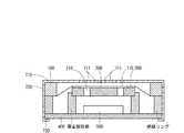
なお、上述したエレクトレットコンデンサマイクロホンは特許請求の範囲の趣旨に適う限り任意に設計変更することが可能である。以下、その設計変更について述べる。図3は、本発明の実施例1の設計変更例に係るエレクトレットコンデンサマイクロホンの模式的断面図である。 The electret condenser microphone described above can be arbitrarily modified as long as it meets the spirit of the claims. The design change will be described below. FIG. 3 is a schematic cross-sectional view of an electret condenser microphone according to a design change example of Embodiment 1 of the present invention.
背極板200は、枠体100内に配置された状態で、振動膜110を押圧するように構成するか否かは任意である。即ち、背極板200は、枠体100内に配置された状態で、振動膜110に所定の空間を有して対向配置される構成とすることができる。この点は、背極741’も同様である。また、前記空間を形成するためにスペーサ300、742’を設けるか否かは任意である。
Whether or not the
スペーサ300については、リング状であるとしたが、これに限定されるものではない。例えば、複数のスペーサ300を背極板200上に環状に配設することができる。
The
スペーサ742’については、背極741’の天板の外周縁部上に絞り加工により形成されるとしたが、これに限定されるものではない。例えば、スペーサ300と同様に背極741’の天板の外周縁部上に絶縁層を印刷により形成するようにしても良い。この場合には、前述の通り、複数のスペーサを背極741’上に環状に配設することができる。
The
突起部740’については、カプセル700’の底板部710’の中央部をプレス絞り加工することにより作成されるとしたが、これに限定されるものではない。例えば、後述の如くカプセル700’を樹脂成型品とする場合には、当該カプセル700’樹脂成型時に突起部を作成することができる。この場合、背極上に複数のスペーサを環状に配設することができる。
The
振動膜110は枠体100の下面に設けられているとしたが、上面に設けることが可能である。この場合であっても、背極板200及びスペーサ300の厚みの和、背極741’及びスペーサ742’の厚みの和(即ち、突起部740’の高さ)を枠体100の厚みよりも大きくすることにより、背極板200及びスペーサ300、背極741’及びスペーサ742’が枠体100内に配置された状態で、振動膜110を押圧することができる。
Although the
基板400については、枠体100の上方に配置されるとしたが、下方に配置することも可能である。この場合、図3に示すように、基板400と枠体100との間に絶縁リングを介在させ、カプセル700を介して枠体100を基板400の第2の導電パターンに接続させる。その一方、基板400上に背極板200を保持するリング状の導電保持部を設け、当該導電保持部を介して背極板200を基板400の第1の導電パターンに接続させる。なお、カプセル700の底板部710には複数の音孔711が開設されている。このように設計変更した場合であっても、背極板200が枠体100内に配置され、振動膜110を押圧するようになっていることから、上記実施形態と同様の効果を得ることができる。
The
カプセル700については、導電金属製であるとしたが、絶縁性の樹脂成型品等とすることも可能である。この場合には、カプセルの内面又は外面に導電ラインを形成し、上記実施形態の如く背極板200及び基板400、背極741’のエレクトレット層及び基板400を接続するようにしても良いし、前述のように枠体100及び基板400を接続するようにしても良い。
The
底板部710については、背極板200の位置決め手段として突脈712が設けられているとしたが、これに限定されるものではない。即ち、前記位置決め手段としては背極板200を位置決め保持し得るものである限り、どのようなものを用いても構わない。例えば、底板部710に凹部を設け、当該凹部に背極板200を嵌合させるようにしても良い。
The
上記実施例におけるエレクトレットコンデンサマイクロホンは、エレクトレット層が背極板200、741’の振動膜対向面に設けられたバックエレクトレットコンデンサマイクロホンであるとしたが、振動膜110自体がエレクトレット用の高分子フィルムで構成されたホイルエレクトレットコンデンサマイクロホンとすることも可能である。
The electret condenser microphone in the above embodiment is a back electret condenser microphone in which the electret layer is provided on the vibration film facing surface of the
なお、上記各構成部品の形状、素材及びその数については、同様の機能を実現し得る限り、任意に設計変更可能である。従って、上述したように各構成部品を円形(即ち、丸型)にせず、角形(即ち、角型)とすることも勿論可能である。 In addition, about the shape of each said component, a raw material, and the number, the design change is arbitrarily possible as long as the same function is realizable. Therefore, as described above, it is of course possible to make each component part not a circle (ie, a round shape) but a square shape (ie, a square shape).
100 枠体
110 振動膜
200 背極板
300 スペーサ
700 カプセル
712 突脈(位置決め手段)
700’ カプセル
740’ 突起部
741’ 背極
742’ スペーサ
DESCRIPTION OF
700 'capsule 740' protrusion 741 'back pole 742' spacer
Claims (6)
前記枠体の下面に貼付された振動膜と、
前記枠体内に配置されており且つ上面と下面とを有する背極と、
前記背極の上面に設けられ且つ絶縁性を有するスペーサとを備えており、
前記枠体の下面と前記背極の下面とが同一高さに配置され、前記背極の上面が前記枠体の下面よりも上側に位置し、前記スペーサが当該スペーサの高さ寸法と前記背極の高さ寸法との和の分、前記振動膜を押圧し、前記背極が前記振動膜に所定の空間を有して対向している
ことを特徴とするエレクトレットコンデンサマイクロホン。 A frame having an upper surface and a lower surface ;
A diaphragm attached to the lower surface of the frame,
A back electrode disposed within the frame and having an upper surface and a lower surface;
A spacer provided on the upper surface of the back electrode and having an insulating property;
The lower surface of the frame body and the lower surface of the back electrode are disposed at the same height, the upper surface of the back electrode is positioned above the lower surface of the frame body, and the spacer has a height dimension of the spacer and the back surface of the frame. An electret condenser microphone , wherein the vibrating membrane is pressed by the sum of the height of the pole and the back electrode faces the vibrating membrane with a predetermined space .
前記枠体の下面と前記背極の下面とが設置された設置部を更に備えている
ことを特徴とするエレクトレットコンデンサマイクロホン。 The electret condenser microphone according to claim 1,
An electret condenser microphone , further comprising an installation portion in which a lower surface of the frame body and a lower surface of the back electrode are installed .
前記枠体及び背極を収容するカプセルを更に備えており、
前記カプセルは、前記設置部と、
前記設置部に設けられ、前記背極を位置決め保持する位置決め手段とを有している
ことを特徴とするエレクトレットコンデンサマイクロホン。 The electret condenser microphone according to claim 2,
A capsule containing the frame and the back pole;
The capsule includes the installation unit,
An electret condenser microphone , comprising: positioning means provided in the installation portion for positioning and holding the back electrode .
前記枠体の上面に設置されたゲートリングと、
前記ゲートリング上に設置されており且つ前記ゲートリングに接触した第1導電パターンと、第2導電パターンを有する基板と、
前記基板上に実装され、前記第1導電パターンに接続されたFETと、
導電性を有し且つ前記枠体及び背極を収容するカプセルとを更に備えており、
前記カプセルは、前記設置部と、
前記設置部の外周縁部に立設された周壁部と、
前記周壁部の先端部に設けられ、前記基板に当接し、前記第2導電パターンに接触するカシメ部とを更に有している
ことを特徴とするエレクトレットコンデンサマイクロホン。 The electret condenser microphone according to claim 2 ,
A gate ring installed on the upper surface of the frame,
A first conductive pattern disposed on the gate ring and in contact with the gate ring; and a substrate having a second conductive pattern;
An FET mounted on the substrate and connected to the first conductive pattern;
A capsule having electrical conductivity and containing the frame and the back electrode;
The capsule includes the installation unit,
A peripheral wall portion erected on the outer peripheral edge portion of the installation portion;
An electret condenser microphone , further comprising: a crimping portion provided at a distal end portion of the peripheral wall portion, in contact with the substrate, and in contact with the second conductive pattern .
前記枠体の下面に貼付された振動膜と、
導電性を有するカプセルとを備えており、
前記カプセルは、前記枠体内に挿入された突起部を有し、
前記突起部は、背極と、
前記背極に設けられたスペーサとを有し、
前記枠体の下面が前記カプセルの突起部周りに当接し、前記スペーサが当該スペーサの高さ寸法と前記背極の高さ寸法との和の分、前記振動膜を押圧し、前記背極が前記振動膜に所定の空間を有して対向している
ことを特徴とするエレクトレットコンデンサマイクロホン。 A frame having an upper surface and a lower surface;
A diaphragm attached to the lower surface of the frame,
A capsule having conductivity,
The capsule has a protrusion inserted into the frame;
The protrusion is a back pole,
A spacer provided on the back electrode,
The lower surface of the frame body abuts around the protrusion of the capsule, the spacer presses the vibrating membrane by the sum of the height dimension of the spacer and the height dimension of the back electrode, and the back electrode An electret condenser microphone having a predetermined space facing the vibrating membrane .
前記枠体の上面に設置されたゲートリングと、
前記ゲートリング上に設置されており且つ前記ゲートリングに接触した第1導電パターンと、第2導電パターンを有する基板と、
前記基板上に実装され、前記第1導電パターンに接続されたFETとを更に備えており、
前記カプセルは、前記突起部を有する底板部と、
前記底板部の外周縁部に立設された周壁部と、
前記周壁部の先端部に設けられ、前記基板に当接し、前記第2導電パターンに接触するカシメ部とを更に有している
ことを特徴とするエレクトレットコンデンサマイクロホン。 The electret condenser microphone according to claim 5,
A gate ring installed on the upper surface of the frame,
A first conductive pattern disposed on the gate ring and in contact with the gate ring; and a substrate having a second conductive pattern;
An FET mounted on the substrate and connected to the first conductive pattern;
The capsule has a bottom plate portion having the protrusion,
A peripheral wall portion erected on the outer peripheral edge portion of the bottom plate portion;
An electret condenser microphone , further comprising: a crimping portion provided at a distal end portion of the peripheral wall portion, in contact with the substrate, and in contact with the second conductive pattern .
Priority Applications (5)
| Application Number | Priority Date | Filing Date | Title |
|---|---|---|---|
| JP2008115255A JP4960921B2 (en) | 2008-04-25 | 2008-04-25 | Electret condenser microphone |
| TW098108267A TWI401974B (en) | 2008-04-25 | 2009-03-13 | Electret condenser microphone |
| US12/408,156 US8238587B2 (en) | 2008-04-25 | 2009-03-20 | Electret condenser microphone |
| CN200910135060.3A CN101568056B (en) | 2008-04-25 | 2009-04-22 | Electret condenser microphone |
| EP09251174A EP2112840A3 (en) | 2008-04-25 | 2009-04-24 | Electret condenser microphone |
Applications Claiming Priority (1)
| Application Number | Priority Date | Filing Date | Title |
|---|---|---|---|
| JP2008115255A JP4960921B2 (en) | 2008-04-25 | 2008-04-25 | Electret condenser microphone |
Publications (2)
| Publication Number | Publication Date |
|---|---|
| JP2009267782A JP2009267782A (en) | 2009-11-12 |
| JP4960921B2 true JP4960921B2 (en) | 2012-06-27 |
Family
ID=40902795
Family Applications (1)
| Application Number | Title | Priority Date | Filing Date |
|---|---|---|---|
| JP2008115255A Expired - Fee Related JP4960921B2 (en) | 2008-04-25 | 2008-04-25 | Electret condenser microphone |
Country Status (5)
| Country | Link |
|---|---|
| US (1) | US8238587B2 (en) |
| EP (1) | EP2112840A3 (en) |
| JP (1) | JP4960921B2 (en) |
| CN (1) | CN101568056B (en) |
| TW (1) | TWI401974B (en) |
Families Citing this family (7)
| Publication number | Priority date | Publication date | Assignee | Title |
|---|---|---|---|---|
| CN102111704B (en) * | 2009-12-24 | 2013-06-05 | 谢小明 | Capacitance type microphone |
| CN102075838B (en) * | 2011-03-03 | 2013-12-18 | 深圳市豪恩声学股份有限公司 | Electret microphone |
| US8842858B2 (en) | 2012-06-21 | 2014-09-23 | Invensense, Inc. | Electret condenser microphone |
| US20140037120A1 (en) * | 2012-08-01 | 2014-02-06 | Knowles Electronics, Llc | Microphone Assembly |
| EP3373597B1 (en) * | 2017-03-07 | 2019-08-14 | G.R.A.S. Sound & Vibration A/S | Low profile surface mount microphone |
| CN108966100B (en) * | 2018-06-25 | 2020-02-21 | 歌尔股份有限公司 | MEMS microphone |
| US11671763B2 (en) * | 2021-02-24 | 2023-06-06 | Shure Acquisition Holdings, Inc. | Parylene electret condenser microphone backplate |
Family Cites Families (17)
| Publication number | Priority date | Publication date | Assignee | Title |
|---|---|---|---|---|
| US3963881A (en) * | 1973-05-29 | 1976-06-15 | Thermo Electron Corporation | Unidirectional condenser microphone |
| JPS5219569B2 (en) | 1973-09-20 | 1977-05-28 | ||
| JPS5063026U (en) * | 1973-10-09 | 1975-06-09 | ||
| JPS58207798A (en) * | 1982-05-28 | 1983-12-03 | Toshiba Corp | Transducer |
| JPS58209299A (en) * | 1982-05-29 | 1983-12-06 | Toshiba Corp | Transducer |
| JPS59105800A (en) * | 1982-12-08 | 1984-06-19 | Matsushita Electric Ind Co Ltd | Electrostatic speaker |
| JP2000050393A (en) | 1998-05-25 | 2000-02-18 | Hosiden Corp | Electret condenser microphone |
| CA2315417A1 (en) * | 1999-08-11 | 2001-02-11 | Hiroshi Une | Electret capacitor microphone |
| US6654473B2 (en) * | 2001-05-09 | 2003-11-25 | Knowles Electronics, Llc | Condenser microphone |
| JP3940679B2 (en) | 2003-01-16 | 2007-07-04 | シチズン電子株式会社 | Electret condenser microphone |
| KR200330089Y1 (en) * | 2003-07-29 | 2003-10-11 | 주식회사 비에스이 | Integrated base and electret condenser microphone using the same |
| US7136500B2 (en) * | 2003-08-05 | 2006-11-14 | Knowles Electronics, Llc. | Electret condenser microphone |
| TWI260941B (en) * | 2004-04-27 | 2006-08-21 | Hosiden Corp | Electret capacitor microphone |
| JP2006166078A (en) * | 2004-12-08 | 2006-06-22 | Audio Technica Corp | Condenser microphone unit and condenser microphone |
| KR100675024B1 (en) * | 2005-06-13 | 2007-01-30 | 주식회사 비에스이 | Conductive Base of Condenser Microphone and Condenser Microphone Using the Same |
| US20070003081A1 (en) * | 2005-06-30 | 2007-01-04 | Insound Medical, Inc. | Moisture resistant microphone |
| JP2007129543A (en) * | 2005-11-04 | 2007-05-24 | Hosiden Corp | Electret condenser microphone |
-
2008
- 2008-04-25 JP JP2008115255A patent/JP4960921B2/en not_active Expired - Fee Related
-
2009
- 2009-03-13 TW TW098108267A patent/TWI401974B/en not_active IP Right Cessation
- 2009-03-20 US US12/408,156 patent/US8238587B2/en active Active
- 2009-04-22 CN CN200910135060.3A patent/CN101568056B/en not_active Expired - Fee Related
- 2009-04-24 EP EP09251174A patent/EP2112840A3/en not_active Ceased
Also Published As
| Publication number | Publication date |
|---|---|
| TW200945915A (en) | 2009-11-01 |
| US20090268930A1 (en) | 2009-10-29 |
| CN101568056A (en) | 2009-10-28 |
| EP2112840A3 (en) | 2012-08-29 |
| US8238587B2 (en) | 2012-08-07 |
| JP2009267782A (en) | 2009-11-12 |
| TWI401974B (en) | 2013-07-11 |
| EP2112840A2 (en) | 2009-10-28 |
| CN101568056B (en) | 2015-04-01 |
Similar Documents
| Publication | Publication Date | Title |
|---|---|---|
| JP4960921B2 (en) | Electret condenser microphone | |
| US20100322451A1 (en) | MEMS Microphone | |
| US8023670B2 (en) | Stray capacitance reduced condenser microphone | |
| JP2007036387A (en) | Microphone array | |
| US7184563B2 (en) | Electret condenser microphone | |
| CN108464017B (en) | Microphone and method for manufacturing microphone | |
| WO2009005211A1 (en) | Diaphragm with air groove and condenser microphone using the same | |
| JP5578672B2 (en) | Condenser microphone unit and condenser microphone | |
| JP4477466B2 (en) | Electret condenser microphone | |
| KR20150103454A (en) | Microphone package | |
| JP2004032019A (en) | Capacitor microphone | |
| JP3574601B2 (en) | Semiconductor electret condenser microphone | |
| JP3574770B2 (en) | Front electret condenser microphone | |
| JP4331652B2 (en) | Condenser microphone | |
| KR100544277B1 (en) | Case making a stair and electret condenser microphone using the same | |
| KR100696164B1 (en) | Holder of Back Plate And Condensor MicroPhone Including the same And Assembly Method thereof | |
| JP2007288669A (en) | Electret condenser microphone | |
| KR20090113210A (en) | Electret condenser microphone | |
| US20050053254A1 (en) | Condenser microphone using space efficiently and having no characteristic variations | |
| KR101323431B1 (en) | Condenser microphone and assembling method thereof | |
| JP4362419B2 (en) | Condenser microphone | |
| JPH0523698U (en) | Electret condenser microphone unit | |
| KR100606165B1 (en) | Multi hole Diaphragm For Microphone And Condenser Microphone Using the Same | |
| JP5100154B2 (en) | FIXED POLE UNIT, MANUFACTURING METHOD THEREOF, AND ELECTRET CONdenser Microphone Unit | |
| JP2006261883A (en) | Condenser microphone |
Legal Events
| Date | Code | Title | Description |
|---|---|---|---|
| A621 | Written request for application examination |
Free format text: JAPANESE INTERMEDIATE CODE: A621 Effective date: 20100528 |
|
| A977 | Report on retrieval |
Free format text: JAPANESE INTERMEDIATE CODE: A971007 Effective date: 20111219 |
|
| A131 | Notification of reasons for refusal |
Free format text: JAPANESE INTERMEDIATE CODE: A131 Effective date: 20120106 |
|
| A521 | Request for written amendment filed |
Free format text: JAPANESE INTERMEDIATE CODE: A523 Effective date: 20120201 |
|
| TRDD | Decision of grant or rejection written | ||
| A01 | Written decision to grant a patent or to grant a registration (utility model) |
Free format text: JAPANESE INTERMEDIATE CODE: A01 Effective date: 20120313 |
|
| A01 | Written decision to grant a patent or to grant a registration (utility model) |
Free format text: JAPANESE INTERMEDIATE CODE: A01 |
|
| A61 | First payment of annual fees (during grant procedure) |
Free format text: JAPANESE INTERMEDIATE CODE: A61 Effective date: 20120323 |
|
| FPAY | Renewal fee payment (event date is renewal date of database) |
Free format text: PAYMENT UNTIL: 20150330 Year of fee payment: 3 |
|
| R150 | Certificate of patent or registration of utility model |
Ref document number: 4960921 Country of ref document: JP Free format text: JAPANESE INTERMEDIATE CODE: R150 Free format text: JAPANESE INTERMEDIATE CODE: R150 |
|
| LAPS | Cancellation because of no payment of annual fees |