EP2112399B1 - Frequency tuned damper - Google Patents
Frequency tuned damper Download PDFInfo
- Publication number
- EP2112399B1 EP2112399B1 EP08154917A EP08154917A EP2112399B1 EP 2112399 B1 EP2112399 B1 EP 2112399B1 EP 08154917 A EP08154917 A EP 08154917A EP 08154917 A EP08154917 A EP 08154917A EP 2112399 B1 EP2112399 B1 EP 2112399B1
- Authority
- EP
- European Patent Office
- Prior art keywords
- casing
- lid portion
- frequency tuned
- damper according
- tuned damper
- Prior art date
- Legal status (The legal status is an assumption and is not a legal conclusion. Google has not performed a legal analysis and makes no representation as to the accuracy of the status listed.)
- Active
Links
Images


Classifications
-
- F—MECHANICAL ENGINEERING; LIGHTING; HEATING; WEAPONS; BLASTING
- F16—ENGINEERING ELEMENTS AND UNITS; GENERAL MEASURES FOR PRODUCING AND MAINTAINING EFFECTIVE FUNCTIONING OF MACHINES OR INSTALLATIONS; THERMAL INSULATION IN GENERAL
- F16F—SPRINGS; SHOCK-ABSORBERS; MEANS FOR DAMPING VIBRATION
- F16F7/00—Vibration-dampers; Shock-absorbers
- F16F7/10—Vibration-dampers; Shock-absorbers using inertia effect
- F16F7/104—Vibration-dampers; Shock-absorbers using inertia effect the inertia member being resiliently mounted
- F16F7/108—Vibration-dampers; Shock-absorbers using inertia effect the inertia member being resiliently mounted on plastics springs
Definitions
- the present disclosure relates to a frequency tuned damper, for dampening vibrations in a surface
- the damper comprising a vibration body in the form of a casing having a connector opening, a connector part, which is at least partly enclosed by the casing and connected to the casing via a resilient member in the interior of the casing, the connector opening to allowing the connector part to be attached to the surface, such that the casing is resiliently suspended from the surface, the casing having first and second parts.
- Such a damper may be used e.g. in a vehicle to dampen vibrations in a part of the vehicle for instance when its engine runs at idle speed.
- US-2005/066767-A1 shows a damper assembly where a support member is compressed within an inertia chamber and an elastomer by means of a snap fit retainer member.
- An object of the present disclosure is to provide a frequency tuned damper of the initially mentioned kind that can be produced at a reduced cost.
- the first casing part is then in the form of a can portion and the second casing part is a lid portion.
- the can portion defines an internal space having a mounting opening at one end to receive the resilient member.
- the lid portion is arranged to be attached to the can portion over the mounting opening such as to compress the resilient member into a compressed state in the internal space, and the internal space substantially fully contains the resilient member in the compressed state.
- the internal space tapers in the direction from the mounting opening.
- Such a damper allows the lid portion to be produced in e.g. sheet metal, for instance by a simple punching operation. Only one of the damper casing parts, the can portion, need be produced in a higher cost production method such as casting, machining, cold forming, or pressing of metal powder. Thereby a substantially less expensive damper may be provided as compared with a case where both casing parts would define a substantial portion of the casing's internal space and each would need a considerable weight.
- the resilient member is compressed also in the direction transverse to the direction of insertion, such that the damper can take deal with vibrations directed parallel with the plane of the vibrating surface.
- the internal space may for instance have the form of the frustum of a cone with a top angle less than 60°.
- the connector opening may be located in the can portion or in the lid portion.
- the lid portion may consist of sheet metal or plastic.
- the can portion may consist of sintered metal powder or of machined, cast, or cold formed steel.
- the can portion may comprise a circumferential edge portion forming a flange
- the lid portion may comprise a circumferential portion which is bent to enclose the flange, such that the lid portion is attached to the can portion.
- the can portion may comprise a recess around the mounting opening
- the lid portion may comprise a disc which fits in the recess
- the can portion may comprise a protrusion which is deformed to lock the lid portion in the recess such that the lid portion is attached to the can portion.
- the can portion may comprise a circumferential recess
- the lid portion may comprise a circumferential portion, which is bent to be pressed into the recess, such that the lid portion is attached to the can portion.
- the lid portion may be attached to the can portion by one or more welded joints or by means of a glue joint.
- the connector part may have a protruding portion, which extends through the connector opening.
- the present invention relates in general to frequency tuned dampers.
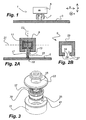
- An example of such a damper 1 is schematically illustrated in fig 1 .
- the damper 1 is used to dampen vibrations in a surface 3, and comprises a vibration body 5 and at least one elastic element 7, which are attached to the surface 3 and together provide a spring-mass system.
- the mass m of the vibration body 5, and the stiffness k and damping c of the elastic element 7 are selected to provide a damping effect on the surface 3, which can be expected to vibrate at a predetermined target frequency.
- the vibration body is caused to oscillate at the same frequency as the surface but out of phase with the latter, such that the vibration of the surface is substantially dampened.
- the vibration body may vibrate with an amplitude substantially greater than the vibration amplitude of the surface.
- the general concept of a frequency tuned damper as illustrated in fig 1 is well known per se.
- Fig 2A shows in cross-section schematically a conceivable outer-mass damper.
- the vibration body (cf. 5, fig 1 ) is in the form of a casing 9, having an interior space.
- the casing 9 has a considerable mass and is intended to be resiliently suspended from a surface 3.
- the damper further has a connector part 11, which is partly enclosed by the casing 9 and is connected to the casing 9 via a resilient member 13 in the casing interior.
- the resilient member 13 constitutes the elastic element of fig 1 .
- the casing has a connector opening 15, and the connector part 11 has a protruding portion 17 which extends through this opening 15 to allow the connector part 11 to be attached to the surface 3. Thereby the casing 9 can be resiliently suspended from the surface 3.
- the connector opening 15 is greater than the protruding portion 17 of the connector part 11 to provide room allowing the casing to vibrate in all dimensions. In any case the opening should be big enough to allow the movement of the casing relative to the connector part.
- the connector part 11 can be attached to the surface in a number of ways, typically using a screw 19.
- a connector part without the protruding portion may be provided. Then, a projecting part integral with or attached to the surface to be dampened reaches through the connector opening and is attached to the connector part as will be shown in connection with fig 9 .
- An outer-mass damper can be very easily attached to the surface and does not take up much room. It may further deal with higher vibration frequencies.
- the connector part 11 may be produced as a machined part, as a metal powder part or may be cold formed or cast. It may be circular symmetric with a symmetry axis 23 along which the connector part extends.
- the elastic element 13 may consist of rubber that is vulcanized to the connector part 11 or simply threaded thereon.
- the casing 9 may have first and second parts, which are joined when the damper is assembled. As illustrated in fig 2A , the casing 9 may thus be divided along the line 21.
- Fig 2B accordingly shows a first 25 and a second 27 casing part, the connector opening 15 being located in the second part 27.
- the damper is assembled by sticking the protruding portion 17 of the connector part 11 from the interior 29 of the second part 27 through the connector opening 15.
- the first part 25 is then fitted on top of the upper part of the connector part 11, and the first and second parts 25, 27 are joined by means of bolts (not shown).
- there are different ways to carry out the assembling typically to first fit the connector part 11 in the first casing part 25, and to join the first and second casing parts 25, 27, such that the protruding portion 17 (if any) extends through the connector opening 15.
- the first and second parts may be produced as two die cast parts. This allows both parts to have a considerable weight.
- a die cast operation further allows the production of casing parts with details such as flanges provided with through holes at little extra cost, the through holes being used in the joining of the first and second parts during assembling of the damper. It should be noted, however, that the overall production cost of a die cast part may be relatively high.
- the present disclosure provides an outer-mass damper that may be produced at a lower cost as compared with the damper schematically illustrated in figs 2A and 2B .
- a first casing part is then a can portion 31
- a second casing part is a lid portion 33.
- the can portion 31 defines an internal space 35 which will take up a connector member 37 and a resilient member 39 when the damper is assembled.
- the can portion 31 will usually have at least 80% of the total mass of the vibration body, i.e. leaving a maximum of 20% to the lid portion 33.
- the can portion therefore has relatively thick walls and may be produced e.g. by die casting (e.g. Zink), cold forming or machining (e.g. steel), or may be provided as a sintered metal powder component.
- the can portion 31 has a mounting opening 41 at one end to receive the connector part 37 and the resilient member 39 when the damper is assembled.
- the internal space 35 of the can portion may be tapering from the mounting opening, and may have a frustoconical shape, as will be discussed later.
- the internal space 35 is further large enough to substantially fully contain the resilient member 39 in a state where the resilient member 39 is compressed.
- the lid portion 33 is arranged to be attached to the can portion 31 over the mounting opening 41 when the connector member 37 and the elastic member 39 have been introduced into the internal space. The lid portion 33 then compresses the resilient member 39.
- the lid portion 33 can be attached to the can portion 31 in a number of ways as will be discussed further later.
- the lid portion 33 can be provided as a relatively inexpensive part as compared to the can portion 31.
- the lid portion 33 may thus be made as a punched sheet metal component, with a thickness of e.g. 1-2 mm. If the sheet metal is steel, a high degree of compression of the resilient member 39 is allowed thanks to the strength of the lid portion. Then the damper may be capable of dealing with high frequencies, over the entire audible spectrum.
- Figs 4A and 4B illustrate the damper of fig 3 when assembled, fig 4A being a side view of the generally circular symmetric damper, and fig 4B being a cross-section along the line B-B in fig 4A .
- the amount of compression that the elastic member 39 is subjected to when the lid portion 33 is attached, is a factor determining the spring characteristics of the elastic member and hence the resonance frequency of the assembled damper.
- the inner space of the can portion 31 is tapering to some extent from the mounting opening such that the inner space has the form of a frustum of a cone.
- the elastic member is also compressed to some extent in the radial direction, such that the damper can be made capable of dampening vibrations also in the radial directions (cf. x, y in fig 1 ).
- the can portion 31 has a circumferential edge portion 43 forming a flange at the can portion periphery.
- the lid portion 33 has a circumferential portion 45 that is bent to enclose the edge portion 43 when the resilient member has been compressed in the interior of the casing, thereby attaching the lid portion 33 to the can portion 31. Further alternatives for attaching the lid portion to the can portion will be discussed later.
- the connector opening 15 (cf. fig 3 ), through which the protruding portion of the connector part extends, is located in the lid portion 33.
- Fig 5 illustrates a first alternative example where the connector opening 15 is instead located in the can portion 31.
- the connector opening is large enough to allow the connector part to move also in the radial direction. Radial and axial directions are here generally defined by the axis 48 along which the connector part 37 extends. In order to avoid contamination of the can portion's inner space the connector opening 15 is closed by means of a flexible seal 47, still allowing the connector part to move. The seal is however not necessary in many applications.
- a second opening is provided in the can portion which allows the insertion of a tool when the damper is mounted onto a surface.
- This second opening may thereafter be sealed e.g. by means of a plastic capsule 49.
- the capsule 49 may comprise two parts interconnected by a joint 50. A first ring-shaped part may be attached at the second opening, and a second, circular part may be inserted into the ring-shaped part when the second opening is to be sealed, by folding the capsule at the joint 50.
- Figs 6A and 6B show a cross section of a second alternative example, fig 6B showing enlarged the portion C of fig 6A .
- the lid portion 51 is provided as a flat, circular disc part that may be inserted into a recess 53 in the can portion 55.
- a protrusion 57 at the boundary of the recess is then deformed to lock the lid portion 51 in the recess 53.
- the protrusion may be circumferential or may be provided at a plurality of locations along the boundary of the recess 53.
- the connector opening may be provided in the lid portion or, as shown, in the can portion.
- Fig 7 illustrates a third alternative example.
- This example is similar to the example of fig 4B , but the flange-like edge portion (cf. 43, fig 4B ) of the can portion is replaced by a circumferential recess 59 around the outer periphery of the can portion 61.
- the lid portion 63 has a circumferential portion 65 that is bent to be pressed into the circumferential recess when the resilient member has been compressed in the interior of the casing, thereby attaching the lid portion 63 to the can portion 61.
- the connector opening may be provided in the can portion or, as shown, in the lid portion.
- Fig 8 illustrates a fourth alternative example.
- the lid portion is provided as a flat circular disc 67 having approximately the same width as the can portion 69.
- the disc 67 is welded to the can portion 69 when the elastic member is compressed therein.
- the connector opening may be provided in the can portion or, as shown, in the lid portion. Gluing may be an additional alternative, replacing the welding.
- Fig 9 illustrates a fifth alternative example.
- the connector part 71 does not have a protruding portion and is fully enclosed by the can portion 73.
- the surface 3, the vibrations of which are to be dampened has a protruding portion 75 which connects with the connector part 71 in the can portion 73 interior.
- the can portion 73 has an opening large enough to allow movement of the can portion 73 relative to the protruding portion 75.
Abstract
Description
- The present disclosure relates to a frequency tuned damper, for dampening vibrations in a surface, the damper comprising a vibration body in the form of a casing having a connector opening, a connector part, which is at least partly enclosed by the casing and connected to the casing via a resilient member in the interior of the casing, the connector opening to allowing the connector part to be attached to the surface, such that the casing is resiliently suspended from the surface, the casing having first and second parts.
- Such a damper may be used e.g. in a vehicle to dampen vibrations in a part of the vehicle for instance when its engine runs at idle speed.
-
US-2005/066767-A1 shows a damper assembly where a support member is compressed within an inertia chamber and an elastomer by means of a snap fit retainer member. - A general problem associated with such dampers is to reduce their production cost.
- An object of the present disclosure is to provide a frequency tuned damper of the initially mentioned kind that can be produced at a reduced cost.
- This object is achieved by means of a frequency tuned damper as defined in
claim 1. More specifically, the first casing part is then in the form of a can portion and the second casing part is a lid portion. The can portion defines an internal space having a mounting opening at one end to receive the resilient member. The lid portion is arranged to be attached to the can portion over the mounting opening such as to compress the resilient member into a compressed state in the internal space, and the internal space substantially fully contains the resilient member in the compressed state. The internal space tapers in the direction from the mounting opening. - Such a damper allows the lid portion to be produced in e.g. sheet metal, for instance by a simple punching operation. Only one of the damper casing parts, the can portion, need be produced in a higher cost production method such as casting, machining, cold forming, or pressing of metal powder. Thereby a substantially less expensive damper may be provided as compared with a case where both casing parts would define a substantial portion of the casing's internal space and each would need a considerable weight.
- As the internal space tapers in the direction from the mounting opening, the resilient member is compressed also in the direction transverse to the direction of insertion, such that the damper can take deal with vibrations directed parallel with the plane of the vibrating surface. The internal space may for instance have the form of the frustum of a cone with a top angle less than 60°.
- The connector opening may be located in the can portion or in the lid portion.
- The lid portion may consist of sheet metal or plastic.
- The can portion may consist of sintered metal powder or of machined, cast, or cold formed steel.
- The can portion may comprise a circumferential edge portion forming a flange, and the lid portion may comprise a circumferential portion which is bent to enclose the flange, such that the lid portion is attached to the can portion.
- Alternatively, the can portion may comprise a recess around the mounting opening, the lid portion may comprise a disc which fits in the recess, and the can portion may comprise a protrusion which is deformed to lock the lid portion in the recess such that the lid portion is attached to the can portion.
- As another alternative, the can portion may comprise a circumferential recess , and the lid portion may comprise a circumferential portion, which is bent to be pressed into the recess, such that the lid portion is attached to the can portion.
- As yet another alternative the lid portion may be attached to the can portion by one or more welded joints or by means of a glue joint.
- The connector part may have a protruding portion, which extends through the connector opening.
-
-
Fig 1 illustrates schematically a frequency tuned damper. -
Fig 2A shows in cross-section schematically an outer-mass damper. -
Fig 2B Illustrates one way to provide a vibration body in the form of a casing, having a first and a second casing part. -
Fig 3 is an exploded view illustrating an outer-mass damper with a can and lid casing. -
Figs 4A and 4B illustrate the damper offig 3 when assembled. -
Fig 5 illustrates a first alternative example. -
Figs 6A and 6B illustrate a second alternative example. -
Fig 7 illustrates a third alternative example. -
Fig 8 illustrates a fourth alternative example. -
Fig 9 illustrates a fifth alternative example. - The present invention relates in general to frequency tuned dampers. An example of such a
damper 1 is schematically illustrated infig 1 . Thedamper 1 is used to dampen vibrations in asurface 3, and comprises avibration body 5 and at least one elastic element 7, which are attached to thesurface 3 and together provide a spring-mass system. - The mass m of the
vibration body 5, and the stiffness k and damping c of the elastic element 7 are selected to provide a damping effect on thesurface 3, which can be expected to vibrate at a predetermined target frequency. When the surface vibrates at this frequency, the vibration body is caused to oscillate at the same frequency as the surface but out of phase with the latter, such that the vibration of the surface is substantially dampened. The vibration body may vibrate with an amplitude substantially greater than the vibration amplitude of the surface. The general concept of a frequency tuned damper as illustrated infig 1 is well known per se. -
Fig 2A shows in cross-section schematically a conceivable outer-mass damper. In such a damper, the vibration body (cf. 5,fig 1 ) is in the form of a casing 9, having an interior space. The casing 9 has a considerable mass and is intended to be resiliently suspended from asurface 3. The damper further has a connector part 11, which is partly enclosed by the casing 9 and is connected to the casing 9 via aresilient member 13 in the casing interior. Theresilient member 13 constitutes the elastic element offig 1 . The casing has a connector opening 15, and the connector part 11 has a protruding portion 17 which extends through thisopening 15 to allow the connector part 11 to be attached to thesurface 3. Thereby the casing 9 can be resiliently suspended from thesurface 3. The connector opening 15 is greater than the protruding portion 17 of the connector part 11 to provide room allowing the casing to vibrate in all dimensions. In any case the opening should be big enough to allow the movement of the casing relative to the connector part. The connector part 11 can be attached to the surface in a number of ways, typically using ascrew 19. - As an alternative, a connector part without the protruding portion may be provided. Then, a projecting part integral with or attached to the surface to be dampened reaches through the connector opening and is attached to the connector part as will be shown in connection with
fig 9 . - An outer-mass damper can be very easily attached to the surface and does not take up much room. It may further deal with higher vibration frequencies.
- The connector part 11 may be produced as a machined part, as a metal powder part or may be cold formed or cast. It may be circular symmetric with a
symmetry axis 23 along which the connector part extends. Theelastic element 13 may consist of rubber that is vulcanized to the connector part 11 or simply threaded thereon. - In order to allow an efficient production of the casing 9, and to allow the connector part 11 and the
elastic element 13 to be fitted therein, the casing 9 may have first and second parts, which are joined when the damper is assembled. As illustrated infig 2A , the casing 9 may thus be divided along the line 21.Fig 2B accordingly shows a first 25 and a second 27 casing part, the connector opening 15 being located in thesecond part 27. The damper is assembled by sticking the protruding portion 17 of the connector part 11 from theinterior 29 of thesecond part 27 through theconnector opening 15. Thefirst part 25 is then fitted on top of the upper part of the connector part 11, and the first andsecond parts first casing part 25, and to join the first andsecond casing parts connector opening 15. - The first and second parts may be produced as two die cast parts. This allows both parts to have a considerable weight. A die cast operation further allows the production of casing parts with details such as flanges provided with through holes at little extra cost, the through holes being used in the joining of the first and second parts during assembling of the damper. It should be noted, however, that the overall production cost of a die cast part may be relatively high.
- The present disclosure provides an outer-mass damper that may be produced at a lower cost as compared with the damper schematically illustrated in
figs 2A and 2B . - Generally, as illustrated with a first example in
fig 3 , a first casing part is then a can portion 31 a second casing part is alid portion 33. Thecan portion 31 defines aninternal space 35 which will take up aconnector member 37 and aresilient member 39 when the damper is assembled. Thecan portion 31 will usually have at least 80% of the total mass of the vibration body, i.e. leaving a maximum of 20% to thelid portion 33. The can portion therefore has relatively thick walls and may be produced e.g. by die casting (e.g. Zink), cold forming or machining (e.g. steel), or may be provided as a sintered metal powder component. - The
can portion 31 has a mounting opening 41 at one end to receive theconnector part 37 and theresilient member 39 when the damper is assembled. Theinternal space 35 of the can portion may be tapering from the mounting opening, and may have a frustoconical shape, as will be discussed later. Theinternal space 35 is further large enough to substantially fully contain theresilient member 39 in a state where theresilient member 39 is compressed. - The
lid portion 33 is arranged to be attached to thecan portion 31 over the mounting opening 41 when theconnector member 37 and theelastic member 39 have been introduced into the internal space. Thelid portion 33 then compresses theresilient member 39. Thelid portion 33 can be attached to thecan portion 31 in a number of ways as will be discussed further later. - Thanks to the use of a
can portion 31 that is large enough to substantially contain the elastic member in the compressed state, thelid portion 33 can be provided as a relatively inexpensive part as compared to thecan portion 31. Thelid portion 33 may thus be made as a punched sheet metal component, with a thickness of e.g. 1-2 mm. If the sheet metal is steel, a high degree of compression of theresilient member 39 is allowed thanks to the strength of the lid portion. Then the damper may be capable of dealing with high frequencies, over the entire audible spectrum. -
Figs 4A and 4B illustrate the damper offig 3 when assembled,fig 4A being a side view of the generally circular symmetric damper, andfig 4B being a cross-section along the line B-B infig 4A . - The amount of compression that the
elastic member 39 is subjected to when thelid portion 33 is attached, is a factor determining the spring characteristics of the elastic member and hence the resonance frequency of the assembled damper. As illustrated, the inner space of thecan portion 31 is tapering to some extent from the mounting opening such that the inner space has the form of a frustum of a cone. Thereby, the elastic member is also compressed to some extent in the radial direction, such that the damper can be made capable of dampening vibrations also in the radial directions (cf. x, y infig 1 ). - The
can portion 31 has acircumferential edge portion 43 forming a flange at the can portion periphery. Thelid portion 33 has acircumferential portion 45 that is bent to enclose theedge portion 43 when the resilient member has been compressed in the interior of the casing, thereby attaching thelid portion 33 to thecan portion 31. Further alternatives for attaching the lid portion to the can portion will be discussed later. - In the damper of
figs 4A and 4B , the connector opening 15 (cf.fig 3 ), through which the protruding portion of the connector part extends, is located in thelid portion 33.Fig 5 illustrates a first alternative example where theconnector opening 15 is instead located in thecan portion 31. Returning tofig 4B , the connector opening is large enough to allow the connector part to move also in the radial direction. Radial and axial directions are here generally defined by theaxis 48 along which theconnector part 37 extends. In order to avoid contamination of the can portion's inner space theconnector opening 15 is closed by means of a flexible seal 47, still allowing the connector part to move. The seal is however not necessary in many applications. - At the other end of the casing, a second opening is provided in the can portion which allows the insertion of a tool when the damper is mounted onto a surface. This second opening may thereafter be sealed e.g. by means of a
plastic capsule 49. Thecapsule 49 may comprise two parts interconnected by a joint 50. A first ring-shaped part may be attached at the second opening, and a second, circular part may be inserted into the ring-shaped part when the second opening is to be sealed, by folding the capsule at the joint 50. -
Figs 6A and 6B show a cross section of a second alternative example,fig 6B showing enlarged the portion C offig 6A . In this example, thelid portion 51 is provided as a flat, circular disc part that may be inserted into arecess 53 in thecan portion 55. Aprotrusion 57 at the boundary of the recess is then deformed to lock thelid portion 51 in therecess 53. The protrusion may be circumferential or may be provided at a plurality of locations along the boundary of therecess 53. The connector opening may be provided in the lid portion or, as shown, in the can portion. -
Fig 7 illustrates a third alternative example. This example is similar to the example offig 4B , but the flange-like edge portion (cf. 43,fig 4B ) of the can portion is replaced by acircumferential recess 59 around the outer periphery of thecan portion 61. The lid portion 63 has a circumferential portion 65 that is bent to be pressed into the circumferential recess when the resilient member has been compressed in the interior of the casing, thereby attaching the lid portion 63 to thecan portion 61. The connector opening may be provided in the can portion or, as shown, in the lid portion. -
Fig 8 illustrates a fourth alternative example. In this case, the lid portion is provided as a flat circular disc 67 having approximately the same width as thecan portion 69. The disc 67 is welded to thecan portion 69 when the elastic member is compressed therein. The connector opening may be provided in the can portion or, as shown, in the lid portion. Gluing may be an additional alternative, replacing the welding. -
Fig 9 illustrates a fifth alternative example. In this case, theconnector part 71 does not have a protruding portion and is fully enclosed by thecan portion 73. Instead, thesurface 3, the vibrations of which are to be dampened, has a protrudingportion 75 which connects with theconnector part 71 in thecan portion 73 interior. Thecan portion 73 has an opening large enough to allow movement of thecan portion 73 relative to the protrudingportion 75. - The invention is not restricted to the described embodiments and may be altered in different ways within the scope of the appended claims. For instance, even if the can portion described above has a circular cross-section, other examples are conceivable, e.g. an elliptic or even a rectangular cross section. Additionally, in some applications non-metal lid portions, e.g. plastic lid portions may be conceivable.
Claims (14)
- A frequency tuned damper, for dampening vibrations in a surface, the damper comprising a vibration body in the form of a casing (9) having a connector opening (15), a connector part (11), which is at least partly enclosed by the casing and connected to the casing via a resilient member (13) in the interior of the casing, said connector opening allowing the connector part to be connected to the surface, such that the casing is resiliently suspended from the surface, the casing having first and second parts, the first casing part is a can portion (31; 55; 61; 69; 73) and the second casing part is a lid portion (33; 51; 63; 67), wherein the can portion defines an internal space (35) having a mounting opening (41) at one end to receive the resilient member, the lid portion is arranged to be attached to the can portion over the mounting opening to compress the resilient member into a compressed state, said internal space substantially fully contains the resilient member in the compressed state, characterized in that
the internal space is tapering in the direction from the mounting opening. - A frequency tuned damper according to claim 2, wherein the internal space has the form of the frustum of a cone with a top angle less than 60°.
- A frequency tuned damper according to any of the preceding claims, wherein the connector opening is located in the can portion.
- A frequency tuned damper according to any of the preceding claims, wherein the connector opening is located in the lid portion.
- A frequency tuned damper according to any of the preceding claims, wherein the lid portion consist of sheet metal.
- A frequency tuned damper according to any of the preceding claims, wherein the lid portion consist of plastic.
- A frequency tuned damper according to any of the preceding claims, wherein the can portion consist of sintered metal powder.
- A frequency tuned damper according to any of the preceding claims, wherein the can portion consist of machined, cast, or cold formed steel.
- A frequency tuned damper according to any of the preceding claims, wherein the can portion (31) comprises a circumferential edge portion forming a flange (43), and the lid portion (33) comprises a circumferential portion (45) which is bent to enclose the flange, such that the lid portion is attached to the can portion.
- A frequency tuned damper according to any of claims 1-9, wherein the can portion (55) comprises a recess (53) around the mounting opening, the lid portion comprising a disc (51) which fits in the recess, and the can portion comprises a protrusion (57) which is deformed to lock the lid portion in the recess such that the lid portion is attached to the can portion.
- A frequency tuned damper according to any of claims 1-9, wherein the can portion (61) comprises a circumferential recess (59), and the lid portion (63) comprises a circumferential portion (65) which is bent to be pressed into the recess, such that the lid portion is attached to the can portion.
- A frequency tuned damper according to any of claims 1-9, wherein the lid portion (67) is attached to the can portion (69) by one or more welded joints.
- A frequency tuned damper according to any of claims 1-9, wherein the lid portion (67) is attached to the can portion (69) by means of a glue joint.
- A frequency tuned damper according to any of the preceding claims, wherein the connector part has a protruding portion, which extends through the connector opening.
Priority Applications (8)
| Application Number | Priority Date | Filing Date | Title |
|---|---|---|---|
| EP08154917A EP2112399B1 (en) | 2008-04-22 | 2008-04-22 | Frequency tuned damper |
| AT08154917T ATE516452T1 (en) | 2008-04-22 | 2008-04-22 | FREQUENCY MATCHED DAMPER |
| ES08154917T ES2368801T3 (en) | 2008-04-22 | 2008-04-22 | TUNED FREQUENCY SHOCK ABSORBER. |
| US12/988,345 US8950736B2 (en) | 2008-04-22 | 2009-03-19 | Frequency tuned damper |
| JP2011505383A JP5350462B2 (en) | 2008-04-22 | 2009-03-19 | Tuning frequency damper |
| PCT/EP2009/002039 WO2009129901A1 (en) | 2008-04-22 | 2009-03-19 | Frequency tuned damper |
| CN200980114067.5A CN102016345B (en) | 2008-04-22 | 2009-03-19 | Frequency tuned damper |
| KR1020107025289A KR101462134B1 (en) | 2008-04-22 | 2009-03-19 | Frequency tuned damper |
Applications Claiming Priority (1)
| Application Number | Priority Date | Filing Date | Title |
|---|---|---|---|
| EP08154917A EP2112399B1 (en) | 2008-04-22 | 2008-04-22 | Frequency tuned damper |
Publications (2)
| Publication Number | Publication Date |
|---|---|
| EP2112399A1 EP2112399A1 (en) | 2009-10-28 |
| EP2112399B1 true EP2112399B1 (en) | 2011-07-13 |
Family
ID=39712391
Family Applications (1)
| Application Number | Title | Priority Date | Filing Date |
|---|---|---|---|
| EP08154917A Active EP2112399B1 (en) | 2008-04-22 | 2008-04-22 | Frequency tuned damper |
Country Status (8)
| Country | Link |
|---|---|
| US (1) | US8950736B2 (en) |
| EP (1) | EP2112399B1 (en) |
| JP (1) | JP5350462B2 (en) |
| KR (1) | KR101462134B1 (en) |
| CN (1) | CN102016345B (en) |
| AT (1) | ATE516452T1 (en) |
| ES (1) | ES2368801T3 (en) |
| WO (1) | WO2009129901A1 (en) |
Cited By (1)
| Publication number | Priority date | Publication date | Assignee | Title |
|---|---|---|---|---|
| DE102019125701A1 (en) * | 2019-09-24 | 2021-04-08 | Vibracoustic Ag | Damping device and method for its assembly |
Families Citing this family (11)
| Publication number | Priority date | Publication date | Assignee | Title |
|---|---|---|---|---|
| JP5923397B2 (en) * | 2012-06-29 | 2016-05-24 | 株式会社ショーワ | Seat damper |
| JP6197201B2 (en) * | 2013-11-15 | 2017-09-20 | 本田技研工業株式会社 | Airbag mounting structure |
| KR101648426B1 (en) | 2014-12-16 | 2016-08-16 | 주식회사 대흥알앤티 | Dynamic damper |
| KR101648427B1 (en) | 2014-12-16 | 2016-08-16 | 주식회사 대흥알앤티 | Dynamic damper |
| CN105422709A (en) * | 2015-11-26 | 2016-03-23 | 安徽鼎远金属制品有限公司 | Outer damping sleeve |
| CN105422708A (en) * | 2015-11-26 | 2016-03-23 | 安徽鼎远金属制品有限公司 | Outer damping sleeve |
| JP6824715B2 (en) * | 2016-12-07 | 2021-02-03 | Toyo Tire株式会社 | Dynamic damper |
| US10156278B2 (en) * | 2017-02-15 | 2018-12-18 | Honda Motor Co., Ltd. | Dynamic damper apparatus with retaining structure |
| EP3499076B1 (en) * | 2017-12-15 | 2021-03-31 | Vibracoustic Forsheda AB | A damper unit, a damper assembly, and a method for making a damper unit |
| DE102018108316B4 (en) * | 2018-04-09 | 2020-01-16 | Thyssenkrupp Ag | Connection, arrangement and method for a vibration damper and an attachment of a wheel suspension |
| DE102019104386A1 (en) * | 2019-02-21 | 2020-08-27 | Vibracoustic Ag | Vibration absorber |
Family Cites Families (20)
| Publication number | Priority date | Publication date | Assignee | Title |
|---|---|---|---|---|
| US3196710A (en) * | 1963-07-22 | 1965-07-27 | Thomas H Peirce | Damper |
| US4046230A (en) * | 1976-07-14 | 1977-09-06 | Houdaille Industries, Inc. | Tuned torsional viscous dampers |
| US4378865A (en) * | 1980-12-10 | 1983-04-05 | Houdaille Industries, Inc. | Rubber and viscous/rubber torsional dampers and method of making the same |
| JPS5991985U (en) * | 1982-12-13 | 1984-06-22 | 川崎重工業株式会社 | Handlebar vibration isolator |
| JPS6080043U (en) | 1983-11-07 | 1985-06-04 | 新日本製鐵株式会社 | Mobile ladle refining equipment |
| US4703470A (en) * | 1985-08-15 | 1987-10-27 | Priam (Delaware) Corporation | Dynamic absorber device for use with disk drives |
| US4850243A (en) * | 1986-06-04 | 1989-07-25 | Household Manufacturing, Inc. | Uniform strain vibration damper |
| JPH0680043U (en) * | 1993-04-19 | 1994-11-08 | 東海ゴム工業株式会社 | Dynamic damper |
| CN2192848Y (en) | 1994-05-20 | 1995-03-22 | 王松柏 | Universal damping device for refrgerator |
| DE19856643A1 (en) * | 1998-12-03 | 2000-06-08 | Siemens Ag | Noise reduction method for coil-wound items, such as chokes and transformers |
| SE524074C2 (en) * | 2000-06-02 | 2004-06-22 | Forsheda Ab | Apparatus for damping vibration of a vibrating surface and methods for mounting such a device |
| JP2004148994A (en) * | 2002-10-30 | 2004-05-27 | Tokai Rubber Ind Ltd | Impact absorbing member for vehicle |
| US20050066767A1 (en) | 2003-09-26 | 2005-03-31 | Patterson John W. | Snap together linear vibration damper and method for assembly related application |
| JP2005180574A (en) | 2003-12-19 | 2005-07-07 | Tokai Rubber Ind Ltd | Dynamic damper |
| DE102005009677B4 (en) * | 2005-02-28 | 2007-01-04 | Carl Freudenberg Kg | vibration absorber |
| CN2886205Y (en) | 2006-03-28 | 2007-04-04 | 盐城市宏达人工环境工程有限公司 | Spring shock absorber |
| CN200958542Y (en) | 2006-05-19 | 2007-10-10 | 中国航天科技集团公司第一研究院第一设计部 | Efficient lateral-displacement damping vibration absorber |
| CN1888464A (en) * | 2006-07-21 | 2007-01-03 | 郑钢铁 | Multifunction metal rubber flexible connecting piece |
| DE202006016948U1 (en) * | 2006-11-06 | 2007-02-01 | Trw Automotive Safety Systems Gmbh | Device for damping vibrations of a steering wheel or a gasbag module comprises an adjustable control element which cooperates with the damping element and alters the natural frequency of the device |
| JP4955100B2 (en) * | 2007-04-16 | 2012-06-20 | トレレボルグ、オートモーティブ、フォルシェダ、アクチボラグ | Damper |
-
2008
- 2008-04-22 AT AT08154917T patent/ATE516452T1/en not_active IP Right Cessation
- 2008-04-22 ES ES08154917T patent/ES2368801T3/en active Active
- 2008-04-22 EP EP08154917A patent/EP2112399B1/en active Active
-
2009
- 2009-03-19 KR KR1020107025289A patent/KR101462134B1/en active IP Right Grant
- 2009-03-19 WO PCT/EP2009/002039 patent/WO2009129901A1/en active Application Filing
- 2009-03-19 CN CN200980114067.5A patent/CN102016345B/en active Active
- 2009-03-19 JP JP2011505383A patent/JP5350462B2/en active Active
- 2009-03-19 US US12/988,345 patent/US8950736B2/en active Active
Cited By (2)
| Publication number | Priority date | Publication date | Assignee | Title |
|---|---|---|---|---|
| DE102019125701A1 (en) * | 2019-09-24 | 2021-04-08 | Vibracoustic Ag | Damping device and method for its assembly |
| DE102019125701B4 (en) | 2019-09-24 | 2023-01-26 | Vibracoustic Se | Damping device and method for its assembly |
Also Published As
| Publication number | Publication date |
|---|---|
| EP2112399A1 (en) | 2009-10-28 |
| CN102016345A (en) | 2011-04-13 |
| ES2368801T3 (en) | 2011-11-22 |
| ATE516452T1 (en) | 2011-07-15 |
| JP2011518298A (en) | 2011-06-23 |
| KR101462134B1 (en) | 2014-11-14 |
| US8950736B2 (en) | 2015-02-10 |
| WO2009129901A1 (en) | 2009-10-29 |
| KR20100135898A (en) | 2010-12-27 |
| CN102016345B (en) | 2013-07-31 |
| US20110049776A1 (en) | 2011-03-03 |
| JP5350462B2 (en) | 2013-11-27 |
Similar Documents
| Publication | Publication Date | Title |
|---|---|---|
| EP2112399B1 (en) | Frequency tuned damper | |
| JP5552059B2 (en) | Axial damped fluid mount assembly | |
| US10006514B2 (en) | Damper | |
| JP6045257B2 (en) | Vibration isolator | |
| WO2016092917A1 (en) | Fluid-filled vibration damping device | |
| KR101329478B1 (en) | Liquid sealed mount and method of assembling the same | |
| JP2006234046A (en) | Vibration isolator | |
| US20030001322A1 (en) | Fluid-filled vibration damping device | |
| US10589615B2 (en) | Decoupler for a hydraulic engine mount | |
| JPH04119649U (en) | Fluid-filled mounting device | |
| JP6381345B2 (en) | Torsional rubber damper | |
| CA2315966C (en) | Fluid-filled vibration damping device having improved partition structure | |
| JP5284463B2 (en) | Liquid-filled vibration isolator | |
| JP4081421B2 (en) | Anti-vibration mount assembly | |
| JP2022059388A (en) | Suspension mount | |
| JP2009085315A (en) | Cylindrical type antivibration device | |
| JP4077007B2 (en) | Liquid filled vibration isolator and liquid filled vibration isolator unit | |
| JP4669329B2 (en) | Dynamic damper | |
| JP2015212555A (en) | Vibration control structure of rotor | |
| US20050066767A1 (en) | Snap together linear vibration damper and method for assembly related application | |
| JP2010032023A (en) | Fluid-filled vibration isolation device | |
| JP4016343B2 (en) | Anti-vibration actuator and active vibration isolator using the same | |
| JP5336299B2 (en) | Vibration isolator | |
| JP6704807B2 (en) | Anti-vibration device | |
| JP2005188716A (en) | Dynamic damper |
Legal Events
| Date | Code | Title | Description |
|---|---|---|---|
| PUAI | Public reference made under article 153(3) epc to a published international application that has entered the european phase |
Free format text: ORIGINAL CODE: 0009012 |
|
| AK | Designated contracting states |
Kind code of ref document: A1 Designated state(s): AT BE BG CH CY CZ DE DK EE ES FI FR GB GR HR HU IE IS IT LI LT LU LV MC MT NL NO PL PT RO SE SI SK TR |
|
| AX | Request for extension of the european patent |
Extension state: AL BA MK RS |
|
| 17P | Request for examination filed |
Effective date: 20100305 |
|
| 17Q | First examination report despatched |
Effective date: 20100330 |
|
| AKX | Designation fees paid |
Designated state(s): AT BE BG CH CY CZ DE DK EE ES FI FR GB GR HR HU IE IS IT LI LT LU LV MC MT NL NO PL PT RO SE SI SK TR |
|
| RAP1 | Party data changed (applicant data changed or rights of an application transferred) |
Owner name: TRELLEBORG FORSHEDA AB |
|
| GRAP | Despatch of communication of intention to grant a patent |
Free format text: ORIGINAL CODE: EPIDOSNIGR1 |
|
| GRAS | Grant fee paid |
Free format text: ORIGINAL CODE: EPIDOSNIGR3 |
|
| GRAA | (expected) grant |
Free format text: ORIGINAL CODE: 0009210 |
|
| AK | Designated contracting states |
Kind code of ref document: B1 Designated state(s): AT BE BG CH CY CZ DE DK EE ES FI FR GB GR HR HU IE IS IT LI LT LU LV MC MT NL NO PL PT RO SE SI SK TR |
|
| REG | Reference to a national code |
Ref country code: GB Ref legal event code: FG4D |
|
| REG | Reference to a national code |
Ref country code: CH Ref legal event code: EP |
|
| REG | Reference to a national code |
Ref country code: IE Ref legal event code: FG4D |
|
| REG | Reference to a national code |
Ref country code: DE Ref legal event code: R096 Ref document number: 602008008203 Country of ref document: DE Effective date: 20110908 |
|
| REG | Reference to a national code |
Ref country code: SE Ref legal event code: TRGR |
|
| REG | Reference to a national code |
Ref country code: NL Ref legal event code: VDEP Effective date: 20110713 |
|
| REG | Reference to a national code |
Ref country code: ES Ref legal event code: FG2A Ref document number: 2368801 Country of ref document: ES Kind code of ref document: T3 Effective date: 20111122 |
|
| REG | Reference to a national code |
Ref country code: DE Ref legal event code: R082 Ref document number: 602008008203 Country of ref document: DE Representative=s name: OFFICE ERNEST T. FREYLINGER S.A., LU |
|
| REG | Reference to a national code |
Ref country code: AT Ref legal event code: MK05 Ref document number: 516452 Country of ref document: AT Kind code of ref document: T Effective date: 20110713 |
|
| PG25 | Lapsed in a contracting state [announced via postgrant information from national office to epo] |
Ref country code: PT Free format text: LAPSE BECAUSE OF FAILURE TO SUBMIT A TRANSLATION OF THE DESCRIPTION OR TO PAY THE FEE WITHIN THE PRESCRIBED TIME-LIMIT Effective date: 20111114 Ref country code: HR Free format text: LAPSE BECAUSE OF FAILURE TO SUBMIT A TRANSLATION OF THE DESCRIPTION OR TO PAY THE FEE WITHIN THE PRESCRIBED TIME-LIMIT Effective date: 20110713 Ref country code: FI Free format text: LAPSE BECAUSE OF FAILURE TO SUBMIT A TRANSLATION OF THE DESCRIPTION OR TO PAY THE FEE WITHIN THE PRESCRIBED TIME-LIMIT Effective date: 20110713 Ref country code: LT Free format text: LAPSE BECAUSE OF FAILURE TO SUBMIT A TRANSLATION OF THE DESCRIPTION OR TO PAY THE FEE WITHIN THE PRESCRIBED TIME-LIMIT Effective date: 20110713 Ref country code: BE Free format text: LAPSE BECAUSE OF FAILURE TO SUBMIT A TRANSLATION OF THE DESCRIPTION OR TO PAY THE FEE WITHIN THE PRESCRIBED TIME-LIMIT Effective date: 20110713 Ref country code: NO Free format text: LAPSE BECAUSE OF FAILURE TO SUBMIT A TRANSLATION OF THE DESCRIPTION OR TO PAY THE FEE WITHIN THE PRESCRIBED TIME-LIMIT Effective date: 20111013 Ref country code: IS Free format text: LAPSE BECAUSE OF FAILURE TO SUBMIT A TRANSLATION OF THE DESCRIPTION OR TO PAY THE FEE WITHIN THE PRESCRIBED TIME-LIMIT Effective date: 20111113 Ref country code: NL Free format text: LAPSE BECAUSE OF FAILURE TO SUBMIT A TRANSLATION OF THE DESCRIPTION OR TO PAY THE FEE WITHIN THE PRESCRIBED TIME-LIMIT Effective date: 20110713 |
|
| PG25 | Lapsed in a contracting state [announced via postgrant information from national office to epo] |
Ref country code: AT Free format text: LAPSE BECAUSE OF FAILURE TO SUBMIT A TRANSLATION OF THE DESCRIPTION OR TO PAY THE FEE WITHIN THE PRESCRIBED TIME-LIMIT Effective date: 20110713 Ref country code: GR Free format text: LAPSE BECAUSE OF FAILURE TO SUBMIT A TRANSLATION OF THE DESCRIPTION OR TO PAY THE FEE WITHIN THE PRESCRIBED TIME-LIMIT Effective date: 20111014 Ref country code: PL Free format text: LAPSE BECAUSE OF FAILURE TO SUBMIT A TRANSLATION OF THE DESCRIPTION OR TO PAY THE FEE WITHIN THE PRESCRIBED TIME-LIMIT Effective date: 20110713 Ref country code: SI Free format text: LAPSE BECAUSE OF FAILURE TO SUBMIT A TRANSLATION OF THE DESCRIPTION OR TO PAY THE FEE WITHIN THE PRESCRIBED TIME-LIMIT Effective date: 20110713 Ref country code: CY Free format text: LAPSE BECAUSE OF FAILURE TO SUBMIT A TRANSLATION OF THE DESCRIPTION OR TO PAY THE FEE WITHIN THE PRESCRIBED TIME-LIMIT Effective date: 20110713 Ref country code: LV Free format text: LAPSE BECAUSE OF FAILURE TO SUBMIT A TRANSLATION OF THE DESCRIPTION OR TO PAY THE FEE WITHIN THE PRESCRIBED TIME-LIMIT Effective date: 20110713 |
|
| REG | Reference to a national code |
Ref country code: DE Ref legal event code: R082 Ref document number: 602008008203 Country of ref document: DE Representative=s name: OFFICE FREYLINGER S.A., LU Effective date: 20120109 Ref country code: DE Ref legal event code: R081 Ref document number: 602008008203 Country of ref document: DE Owner name: TRELLEBORG AUTOMOTIVE FORSHEDA AB, SE Free format text: FORMER OWNER: TRELLEBORG FORSHEDA AB, FORSHEDA, SE Effective date: 20120109 |
|
| REG | Reference to a national code |
Ref country code: FR Ref legal event code: TP Owner name: TRELLEBORG AUTOMOTIVE FORSHEDA AB, SE Effective date: 20120130 |
|
| PG25 | Lapsed in a contracting state [announced via postgrant information from national office to epo] |
Ref country code: CZ Free format text: LAPSE BECAUSE OF FAILURE TO SUBMIT A TRANSLATION OF THE DESCRIPTION OR TO PAY THE FEE WITHIN THE PRESCRIBED TIME-LIMIT Effective date: 20110713 Ref country code: SK Free format text: LAPSE BECAUSE OF FAILURE TO SUBMIT A TRANSLATION OF THE DESCRIPTION OR TO PAY THE FEE WITHIN THE PRESCRIBED TIME-LIMIT Effective date: 20110713 |
|
| PLBE | No opposition filed within time limit |
Free format text: ORIGINAL CODE: 0009261 |
|
| STAA | Information on the status of an ep patent application or granted ep patent |
Free format text: STATUS: NO OPPOSITION FILED WITHIN TIME LIMIT |
|
| PG25 | Lapsed in a contracting state [announced via postgrant information from national office to epo] |
Ref country code: RO Free format text: LAPSE BECAUSE OF FAILURE TO SUBMIT A TRANSLATION OF THE DESCRIPTION OR TO PAY THE FEE WITHIN THE PRESCRIBED TIME-LIMIT Effective date: 20110713 Ref country code: EE Free format text: LAPSE BECAUSE OF FAILURE TO SUBMIT A TRANSLATION OF THE DESCRIPTION OR TO PAY THE FEE WITHIN THE PRESCRIBED TIME-LIMIT Effective date: 20110713 |
|
| REG | Reference to a national code |
Ref country code: ES Ref legal event code: PC2A Owner name: TRELLEBORG AUTOMOTIVE FORSHEDA AB Effective date: 20120606 |
|
| 26N | No opposition filed |
Effective date: 20120416 |
|
| PG25 | Lapsed in a contracting state [announced via postgrant information from national office to epo] |
Ref country code: DK Free format text: LAPSE BECAUSE OF FAILURE TO SUBMIT A TRANSLATION OF THE DESCRIPTION OR TO PAY THE FEE WITHIN THE PRESCRIBED TIME-LIMIT Effective date: 20110713 |
|
| REG | Reference to a national code |
Ref country code: GB Ref legal event code: 732E Free format text: REGISTERED BETWEEN 20120614 AND 20120620 |
|
| REG | Reference to a national code |
Ref country code: DE Ref legal event code: R097 Ref document number: 602008008203 Country of ref document: DE Effective date: 20120416 |
|
| PG25 | Lapsed in a contracting state [announced via postgrant information from national office to epo] |
Ref country code: MC Free format text: LAPSE BECAUSE OF NON-PAYMENT OF DUE FEES Effective date: 20120430 |
|
| REG | Reference to a national code |
Ref country code: CH Ref legal event code: PL |
|
| REG | Reference to a national code |
Ref country code: IE Ref legal event code: MM4A |
|
| PG25 | Lapsed in a contracting state [announced via postgrant information from national office to epo] |
Ref country code: CH Free format text: LAPSE BECAUSE OF NON-PAYMENT OF DUE FEES Effective date: 20120430 Ref country code: IE Free format text: LAPSE BECAUSE OF NON-PAYMENT OF DUE FEES Effective date: 20120422 Ref country code: LI Free format text: LAPSE BECAUSE OF NON-PAYMENT OF DUE FEES Effective date: 20120430 |
|
| PG25 | Lapsed in a contracting state [announced via postgrant information from national office to epo] |
Ref country code: BG Free format text: LAPSE BECAUSE OF FAILURE TO SUBMIT A TRANSLATION OF THE DESCRIPTION OR TO PAY THE FEE WITHIN THE PRESCRIBED TIME-LIMIT Effective date: 20111013 |
|
| PG25 | Lapsed in a contracting state [announced via postgrant information from national office to epo] |
Ref country code: MT Free format text: LAPSE BECAUSE OF FAILURE TO SUBMIT A TRANSLATION OF THE DESCRIPTION OR TO PAY THE FEE WITHIN THE PRESCRIBED TIME-LIMIT Effective date: 20110713 |
|
| PG25 | Lapsed in a contracting state [announced via postgrant information from national office to epo] |
Ref country code: TR Free format text: LAPSE BECAUSE OF FAILURE TO SUBMIT A TRANSLATION OF THE DESCRIPTION OR TO PAY THE FEE WITHIN THE PRESCRIBED TIME-LIMIT Effective date: 20110713 |
|
| PG25 | Lapsed in a contracting state [announced via postgrant information from national office to epo] |
Ref country code: LU Free format text: LAPSE BECAUSE OF NON-PAYMENT OF DUE FEES Effective date: 20120422 |
|
| PG25 | Lapsed in a contracting state [announced via postgrant information from national office to epo] |
Ref country code: HU Free format text: LAPSE BECAUSE OF FAILURE TO SUBMIT A TRANSLATION OF THE DESCRIPTION OR TO PAY THE FEE WITHIN THE PRESCRIBED TIME-LIMIT Effective date: 20080422 |
|
| REG | Reference to a national code |
Ref country code: FR Ref legal event code: PLFP Year of fee payment: 9 |
|
| REG | Reference to a national code |
Ref country code: FR Ref legal event code: PLFP Year of fee payment: 10 |
|
| REG | Reference to a national code |
Ref country code: FR Ref legal event code: PLFP Year of fee payment: 11 |
|
| REG | Reference to a national code |
Ref country code: DE Ref legal event code: R082 Ref document number: 602008008203 Country of ref document: DE Representative=s name: OFFICE FREYLINGER S.A., LU Ref country code: DE Ref legal event code: R081 Ref document number: 602008008203 Country of ref document: DE Owner name: VIBRACOUSTIC FORSHEDA AB, SE Free format text: FORMER OWNER: TRELLEBORG AUTOMOTIVE FORSHEDA AB, TRELLEBORG, SE |
|
| REG | Reference to a national code |
Ref country code: ES Ref legal event code: PC2A Owner name: VIBRACOUSTIC FORSHEDA AB Effective date: 20191106 |
|
| PGFP | Annual fee paid to national office [announced via postgrant information from national office to epo] |
Ref country code: FR Payment date: 20230316 Year of fee payment: 16 |
|
| PGFP | Annual fee paid to national office [announced via postgrant information from national office to epo] |
Ref country code: SE Payment date: 20230316 Year of fee payment: 16 Ref country code: IT Payment date: 20230320 Year of fee payment: 16 Ref country code: GB Payment date: 20230316 Year of fee payment: 16 |
|
| PGFP | Annual fee paid to national office [announced via postgrant information from national office to epo] |
Ref country code: ES Payment date: 20230503 Year of fee payment: 16 Ref country code: DE Payment date: 20230317 Year of fee payment: 16 |