EP2111703B1 - Method for sub -packet generation with adaptive bit index - Google Patents
Method for sub -packet generation with adaptive bit index Download PDFInfo
- Publication number
- EP2111703B1 EP2111703B1 EP08766306A EP08766306A EP2111703B1 EP 2111703 B1 EP2111703 B1 EP 2111703B1 EP 08766306 A EP08766306 A EP 08766306A EP 08766306 A EP08766306 A EP 08766306A EP 2111703 B1 EP2111703 B1 EP 2111703B1
- Authority
- EP
- European Patent Office
- Prior art keywords
- starting position
- initial
- bits
- circular buffer
- sub
- Prior art date
- Legal status (The legal status is an assumption and is not a legal conclusion. Google has not performed a legal analysis and makes no representation as to the accuracy of the status listed.)
- Not-in-force
Links
Images


Classifications
-
- H—ELECTRICITY
- H04—ELECTRIC COMMUNICATION TECHNIQUE
- H04L—TRANSMISSION OF DIGITAL INFORMATION, e.g. TELEGRAPHIC COMMUNICATION
- H04L1/00—Arrangements for detecting or preventing errors in the information received
- H04L1/12—Arrangements for detecting or preventing errors in the information received by using return channel
- H04L1/16—Arrangements for detecting or preventing errors in the information received by using return channel in which the return channel carries supervisory signals, e.g. repetition request signals
- H04L1/18—Automatic repetition systems, e.g. Van Duuren systems
- H04L1/1812—Hybrid protocols; Hybrid automatic repeat request [HARQ]
- H04L1/1819—Hybrid protocols; Hybrid automatic repeat request [HARQ] with retransmission of additional or different redundancy
-
- H—ELECTRICITY
- H04—ELECTRIC COMMUNICATION TECHNIQUE
- H04L—TRANSMISSION OF DIGITAL INFORMATION, e.g. TELEGRAPHIC COMMUNICATION
- H04L1/00—Arrangements for detecting or preventing errors in the information received
- H04L1/004—Arrangements for detecting or preventing errors in the information received by using forward error control
- H04L1/0041—Arrangements at the transmitter end
- H04L1/0043—Realisations of complexity reduction techniques, e.g. use of look-up tables
-
- H—ELECTRICITY
- H04—ELECTRIC COMMUNICATION TECHNIQUE
- H04L—TRANSMISSION OF DIGITAL INFORMATION, e.g. TELEGRAPHIC COMMUNICATION
- H04L1/00—Arrangements for detecting or preventing errors in the information received
- H04L1/004—Arrangements for detecting or preventing errors in the information received by using forward error control
- H04L1/0045—Arrangements at the receiver end
- H04L1/0047—Decoding adapted to other signal detection operation
- H04L1/005—Iterative decoding, including iteration between signal detection and decoding operation
-
- H—ELECTRICITY
- H04—ELECTRIC COMMUNICATION TECHNIQUE
- H04L—TRANSMISSION OF DIGITAL INFORMATION, e.g. TELEGRAPHIC COMMUNICATION
- H04L1/00—Arrangements for detecting or preventing errors in the information received
- H04L1/004—Arrangements for detecting or preventing errors in the information received by using forward error control
- H04L1/0056—Systems characterized by the type of code used
- H04L1/0064—Concatenated codes
- H04L1/0066—Parallel concatenated codes
-
- H—ELECTRICITY
- H04—ELECTRIC COMMUNICATION TECHNIQUE
- H04L—TRANSMISSION OF DIGITAL INFORMATION, e.g. TELEGRAPHIC COMMUNICATION
- H04L1/00—Arrangements for detecting or preventing errors in the information received
- H04L1/004—Arrangements for detecting or preventing errors in the information received by using forward error control
- H04L1/0056—Systems characterized by the type of code used
- H04L1/0067—Rate matching
- H04L1/0068—Rate matching by puncturing
-
- H—ELECTRICITY
- H04—ELECTRIC COMMUNICATION TECHNIQUE
- H04L—TRANSMISSION OF DIGITAL INFORMATION, e.g. TELEGRAPHIC COMMUNICATION
- H04L1/00—Arrangements for detecting or preventing errors in the information received
- H04L1/12—Arrangements for detecting or preventing errors in the information received by using return channel
- H04L1/16—Arrangements for detecting or preventing errors in the information received by using return channel in which the return channel carries supervisory signals, e.g. repetition request signals
- H04L1/18—Automatic repetition systems, e.g. Van Duuren systems
- H04L1/1867—Arrangements specially adapted for the transmitter end
- H04L1/1874—Buffer management
-
- H—ELECTRICITY
- H04—ELECTRIC COMMUNICATION TECHNIQUE
- H04L—TRANSMISSION OF DIGITAL INFORMATION, e.g. TELEGRAPHIC COMMUNICATION
- H04L1/00—Arrangements for detecting or preventing errors in the information received
- H04L1/004—Arrangements for detecting or preventing errors in the information received by using forward error control
- H04L1/0056—Systems characterized by the type of code used
- H04L1/0071—Use of interleaving
Definitions
- the present invention relates to a method of retransmitting a packet, and more particularly, to a method of generating a sub-packet in consideration of an offset, which is capable of reducing complexity and improving a coding gain at the time of rate matching in a hybrid automatic repeat request (HARQ) method.
- HARQ hybrid automatic repeat request
- a next-generation mobile communication system requires a high data transmission rate and reliable transmission. Accordingly, a robust channel coding method is required. Since a turbo code has a structure in which two recursive convolutional codes are concatenated in parallel with an interleaver interposed therebetween and has excellent performance because a channel capacity is close to Shannon capacity, the turbo code is called a channel code suitable for the next-generation mobile communication system.
- FIG. 1 is a block diagram showing the configuration of a general apparatus for encoding a turbo code.
- a first constituent encoder 1 receives and encodes information bits and generates first redundant bits and a second constituent encoder 3 receives and encodes the information bits rearranged by an encoder interleaver 2 and generates second redundant bits.
- the first or second redundant bits are parity bits.
- the constituent encoders of the apparatus for encoding the turbo code employs a method of inserting a tail bit and forcedly ending trellis or a circular coding method.
- the circular coding method since an initial state and a final state of the trellis are equably set and an additional bit is not inserted, band efficiency is higher than the method of inserting the tail bit.
- the initial state and the final state are called a circular state.
- the initial state is set to a zero state, encoding is performed, and the final state is obtained.
- the circular state can be calculated using the final state and a specific encoder structure.
- the calculated circular state is set to the initial state and encoding is performed again, thereby generating the redundant bits.
- FIG. 2 is a block diagram showing the configuration of a general apparatus for decoding a turbo code.
- the information bit sequence and the first and second redundant bit sequences output from the apparatus of FIG. 1 are modulated and the modulated bit sequences are transmitted to a receiver having the apparatus for decoding the turbo code of FIG. 2 .
- the receiver receives and demodulates the modulated bit sequences and supplies the demodulated bit sequences to the apparatus for decoding the turbo code of FIG. 2 .
- a first constituent decoder 4 receives and decodes the demodulated information bit sequence and the demodulated first redundant bit sequence and computes extrinsic information of the first constituent decoder 4.
- a decoder interleaver 5' rearranges the extrinsic information of the first constituent decoder 4 and outputs the rearranged extrinsic information to a second constituent decoder 6.
- the second constituent decoder 6 receives and decodes the demodulated information bit sequence, the demodulated second redundant bit sequence and the extrinsic information of the first constituent decoder 4 rearranged by the decoder interleaver 5 and computes extrinsic information of the second constituent decoder 6.
- a decoder deinterleaver 7 rearranges the extrinsic information of the second constituent decoder 6 and outputs the rearranged extrinsic information to the first constituent decoder 4.
- the above-described process corresponds to a first iterative decoding process. Such an iterative decoding process is performed until desired decoding performance is obtained.
- the apparatus for decoding the turbo code includes a plurality of constituent decoders.
- the constituent decoders compute various types of metrics and perform a decoding operation. Such metrics include transition metrics, forward metrics and backward metrics.
- a log likelihood ratio (LLR) of the information bits is calculated on the basis of the forward and backward metrics.
- the HARQ is known well as a link control protocol for requesting re-transmission of a packet to a transmitter in the case where an error occurs in the packet received by the receiver.
- the packet re-transmission operation using the HARQ is divided into a rate matching process performed by the transmitter and a de-rate matching process performed by the receiver.
- a process of converting a codeword packet encoded at a mother code rate into a sub-packet having a size to be transmitted by the transmitter is called sub-packet generation or rate matching (RM).
- An example of the rate matching includes circular buffer based rate matching (CBRM).
- CBRM circular buffer based rate matching
- a codeword packet having a mother code rate is stored in a bitwise circular buffer (CB).
- the CB indicates a buffer having circular characteristics in which, when the buffer is accessed, a first bit index of the buffer is accessed after a last bit index of, the buffer is accessed.
- the sub-packets necessary for transmission are consecutive indexes of the buffer and are generated by retrieving a portion of the codeword packet stored in the circular buffer.
- an index of a buffer in which the sub-packet is started is called a starting position and an index of a buffer in which the sub-packet is ended is called an ending position.
- RV redundancy version
- the transmitter Tx transmits the sub-packets via a data channel and transmits the RV information of the generated sub-packets via a control channel.
- the receiver Rx maps the sub-packets received via the data channel to the accurate position of the codeword packet using the RV information received via the control channel.
- the circular buffer is divided into a physical circular buffer and a virtual circular buffer according to implementation methods.
- the codeword packet which is forward error correction (FEC)-encoded at the mother code rate is stored in the CB
- systematic bits and parity bits of the codeword packet are interleaved on the sub-block level
- the interleaved systematic bits are first stored in the CB
- the interleaved parity bits are then stored in the CB.
- filler bits inserted into the codeword packet and dummy bits inserted for interleaving may be removed. If the filler bits and the dummy bits are not removed, the filler bits and the dummy bits may be removed in the process of generating the sub-packets, if necessary.
- a memory having a matrix shape which is used for interleaving the systematic bits and the parity bits, is used instead of using an additional circular buffer memory.
- the codeword packet which is FEC-encoded at the mother code rate is stored in an interleaver matrix in order to divide the codeword into the systematic bits and the parity bits and interleave the systematic bits and the parity bits.
- the memory is accessed in consideration of an interleaving pattern.
- the sub-packets necessary for all the HARQ transmission may be generated by selecting one of V starting position candidates. Accordingly, the RV information indicates one of V agreed starting positions regardless of the number of times of HARQ transmission.
- a method of defining the RV information indicating the starting position for generating the sub-packet includes a fixed RV and an adaptive RV.
- the size N of the circular buffer is divided by the number V of starting position candidates, and V fixed positions are defined on the circular buffer at a gap of N/V therebetween.
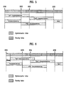
- FIG. 3 is a view showing an embodiment of the HARQ transmission in the case where the starting positions of four fixed RVs are used.
- a static channel is used and the length of the sub-packet used for each HARQ transmission is constant and is greater than N/3 or less than N/2.
- a first transmission indicates a sub-packet used for initial transmission using the HARQ Method and other transmissions indicate sub-packets which are retransmitted three times using the HARQ method.
- N indicates the size of the CB.
- FIG. 3 shows the case where the overall codeword packet stored in the circular buffer cannot be transmitted although the length of the sub-packet used for HARQ transmission is equal to or greater than N/3 and the initial transmission and two re-transmissions are performed.
- the adaptive RV is developed for solving the disadvantages of the fixed RV.
- the adaptive RV is a method of defining the starting position of the RV using the variable length of the sub-packet used for each HARQ transmission.
- a sub-packet having a smallest overlapping portion between the sub-packet transmitted previously and the sub-packet which will be transmitted in the i th HARQ transmission or a sub-packet having a minimized gap with the position of the sub-packet transmitted previously may be selected and transmitted. It is possible to increase the HARQ coding gain by the selection of the sub-packet.
- FIG. 4 is a view showing a method of selecting and transmitting the sub-packet having a minimized gap with the position of the sub-packet transmitted previously.
- the transmitter transmits the sub-packet via the data channel and transmits the RV information via the control channel.
- the receiver can map the sub-packet transmitted via the data channel to the accurate position of the codeword packet using the RV information transmitted via the control channel.
- FIG. 5 is a view showing an embodiment of the HARQ transmission using the starting positions of four adaptive RVs using Equation 1.
- a static channel is used and the length of the sub-packet used for each HARQ transmission is constant and is greater than N/3 or less than N/2, similar to FIG. 3 .
- the length of the sub-packet used for each HARQ transmission is identical and the length of the sub-packet is equal to or greater than N/3, it can be seen that the overall codeword packet stored in the circular buffer can be transmitted by three transmissions. Accordingly, it is possible to obtain a maximum coding gain by a smaller number of times of HARQ re-transmission.
- the length of the sub-packet transmitted for each HARQ transmission is not changed. If the adaptive RV is used, since the gap between the starting position candidates used for all the HARQ transmissions is equal to the length of the sub-packet, incremental redundancy (IR) having the characteristics that the sub-packets used for all the HARQ transmissions are maximally orthogonal to each other can be realized.
- IR incremental redundancy
- An object of the present invention devised to solve the problem lies on a simple method of increasing a coding gain at the time of the generation of a sub-packet in the case where a physical circular buffer is used and computing a gap between starting position candidates in the case where a virtual circular buffer is used, using an adaptive RV.
- Another object of the present invention devised to solve the problem lies on a method of deciding a starting position in consideration of dummy bits and filler bits to be removed and a variable length of a sub-packet in the case where the virtual circular buffer is used.
- the object of the present invention can be achieved by providing a method of generating a sub-packet in consideration of an offset, for re-transmission of a packet from a codeword stored in a circular buffer.
- the present invention it is possible to efficiently decide the starting position of a sub-packet to be transmitted adaptively with respect to a variable packet length, improving a coding gain, reducing complexity, and reducing a calculation amount.
- the starting position of the sub-packet which will be used for the initial transmission is decided such that the predetermined portion of the systematic bits are punctured.
- An adaptive bit index based redundant version considering the puncturing of the systematic bits is described in a linear circular buffer as follows. That is, a method of deciding the starting position of the sub-packet necessary for the HARQ re-transmission in consideration of the amount of systematic bits punctured in the HARQ initial transmission is described as follows.
- the starting position of the sub-packet which will be used for the initial transmission is decided such that the predetermined portion of the systematic bits is punctured.
- the sub-packet including the portion of the codeword packet punctured in the initial transmission is transmitted in the re-transmission step.
- the HARQ method using a circular buffer based rate matching when the codeword packet is stored in the circular buffer, the systematic bits are first stored. Accordingly, in order to generate the sub-packet in which the systematic bits to be used for the initial transmission are punctured, the starting position S initial of the sub-packet of the initial transmission is decided such that the index of the circular buffer is skipped by a necessary number.
- CBRM circular buffer based rate matching
- the starting position S initial used for the initial transmission needs to be always considered.
- the starting position of the sub-packet which will be used for the re-transmission is obtained by Equation 1 without considering the starting position S initial of the sub-packet of the initial transmission, the incremental redundancy (IR) having characteristics that the transmitted sub-packets are maximally orthogonal to each other can not be realized.
- FIG. 6 is a view showing the starting position of the sub-packet of the HARQ re-transmission without considering the starting position S initial of the sub-packet of the initial transmission in the static channel.
- the IR having the characteristic that the sub-packets are orthogonal to each other cannot be realized when the starting position of the sub-packet of the HARQ re-transmission without considering the starting position S initial used for the initial transmission in the static channel is used.
- the present invention does not exclude the embodiment of FIG. 6 .
- the starting position S initial used for the initial transmission may not be considered in the initial transmission and may be considered in the re-transmission method as one embodiment.
- a sub-packet having a smallest overlapping portion between the sub-packet transmitted previously and the sub-packet which will be transmitted in the i th HARQ transmission or a sub-packet having a minimized gap with the position of the sub-packet transmitted previously may be selected and transmitted when the sub-packet which will be transmitted in the i th HARQ transmission is decided.
- the HARQ coding gain can be increased by the selection of the sub-packet.
- the offset that is, S initial , may vary according to the identifiers of the transmitted sub-packets.
- the amount of punctured systematic bits is ⁇
- the code rate of the sub-packet used for the initial transmission is R s
- the threshold of the code rate for deciding the puncturing of the systematic bits is R ⁇ . If R s >R ⁇ , the systematic bits are punctured.
- the IR having the characteristics that the transmitted sub-packets are maximally orthogonal to each other can be realized as shown in FIG. 7 .
- the starting position of the fixed RV uses V column indexes on a matrix memory.
- the adaptive RV requires a method of deciding a gap between starting position candidates expressed by the column index of the matrix memory in consideration of the variable length of the sub-packet and filler bits and dummy bits inserted.
- the virtual circular buffer in order to obtain the gap between the starting position candidates of the RV, in the embodiment of the present invention, the virtual circular buffer may be constituted by an R ⁇ C matrix.
- the circular buffer In order to generate a sub-packet from a codeword packet stored in the circular buffer having the matrix shape, the circular buffer is accessed column by column or row by row in consideration of an interleaving pattern.
- the case where the circular buffer is accessed column by column will be described.
- the column In the case where the circular buffer is accessed row by row, the column may be changed to the row and the description of the row may be changed to the column.
- Accessing of the matrix row by row indicates that column elements in a leftmost column are accessed one by one from a 0 th row to an R-1 th row.
- the V starting positions in the circular buffer having the matrix shape indicate V column indexes.
- the circular buffer has a matrix structure and the length of the codeword is smaller than R ⁇ C, that is, is not a multiple of R or a multiple of C
- the matrix circular buffer cannot be filled by the codeword
- dummy bits are filled in the matrix circular buffer.
- the dummy bits are skipped.
- the length of information bits input to the encoder is restricted and the length of systematic bits input to the encoder is smaller than the agreed length of information bits
- filler bits are inserted into the information bits so as to be matched with the agreed length.
- the filler bits inserted the filler bits inserted into the information bits and parity bits generated by the inserted filler bits are present in the codeword.
- the starting position of the sub-packet may be restricted to a position which becomes a multiple of R.
- the starting positions of all the sub-packets are restricted to column indexes.
- the present embodiment relates to a method of deciding the adaptive starting position with respect to the variable length of the sub-packet in each HARQ transmission when the starting position is a multiple of R in the circular buffer having the R ⁇ C matrix shape.
- the present embodiment relates to a method of deciding the starting position of the sub-packet according to the ending position of the previous adjacent sub-packet in consideration of the length of the sub-packet to be transmitted.
- the column address A initial of the starting position S initial used for the initial transmission is 0. If ⁇ initial columns are omitted in consideration of the puncturing of the systematic bits in the HARQ initial transmission, the column address A initial of the starting position S initial used for the initial transmission is R ⁇ initial . Accordingly, the starting position of the sub-packet is decided in consideration of A initial in all HARQ transmissions.
- the column address A j is expressed by Equation 5.
- a j R ⁇ c j - 1 + floor ⁇ r j - 1 / R - 1 where, the ceil indicates a ceil operation.
- the column address A j of the starting position S j may be fixed to R ⁇ c j-1 .
- the start position candidates of the sub-packets which will be transmitted in the i th HARQ transmission are decided using Equation 4.
- a sub-packet having a smallest overlapping portion between the sub-packet transmitted previously and the sub-packet which will be transmitted in the i th HARQ transmission or a sub-packet having a minimized gap with the position of the sub-packet transmitted previously may be selected and transmitted when the sub-packet which will be transmitted in the i th HARQ transmission is decided.
- the HARQ coding gain can be increased by the selection of the sub-packet. If the channel is static and Equation 4 is used, the sub-packet transmitted in each HARQ transmission has 0 or one column index overlapping with the adjacent sub-packet and thus 0 to R-1 bits overlap with the bits of the adjacent sub-packet.
- Equation 4 The case where the column indexes fixed in all the HARQ transmissions are used as the starting positions of the sub-packets is compared with Equation 4. It is assumed that a R*96 circular buffer is used, the channel is static, and the length L of the sub-packet to be transmitted is R*32 ⁇ L ⁇ R*33.
- RV information RV0 is a 0 th column index
- RV information RV1 is a 24 th column index
- RV information RV2 is a 48 th column index
- RV information RV3 is a 72 nd column index. If the RV information RV0 is used in the initial transmission, the RV information RV2 is used in the second transmission, and the RV information RV1 or RV3 is used in the third transmission, the overlapping amount of the transmitted sub-packet can be minimized.
- the overlapping amount of the transmitted sub-packet can be minimized.
- FIG. 10 is a view showing another example of a method of generating a sub-packet in consideration of an offset according to another embodiment of the present invention.
- the embodiment of FIG. 10 relates to a method of deciding the starting position with respect to the variable length of the sub-packet in each HARQ transmission in a circular buffer having an R ⁇ C matrix shape.
- the starting position c initial which will be used for the initial transmission is decided. Similar to the physical circular buffer, in the case where the sub-packet having the high code rate should be transmitted in the initial transmission, ⁇ c columns of the matrix circular buffer are skipped such that the predetermined portion of the systematic bits is punctured, thereby deciding the starting position of the initial transmission. If the puncturing of the systematic bits is decided according to the code rate of the sub-packet used for the initial transmission as expressed by Equation 3, the starting position c initial is expressed by Equation 4.
- the starting position c initial may be fixed to ⁇ c . If the systematic bits are not punctured, ⁇ c is 0.
- c initial ⁇ c ⁇ R s / R ⁇
- Equation 7 mod indicates a modulo operation.
- FIG. 10 shows the starting column index c i,1 and the starting column index c i,2 operated by Equation 7.
- the column interval between c i,1 and c i,2 is the starting position interval ⁇ i .
- ⁇ i of Equation 7 can be obtained by the following method in consideration of the filler bits and the dummy bits which are present in the circular buffer and the length of the sub-packet.
- FIG. 11 is a view showing an example in which an initial starting position is 3 and a starting position interval is 2 in FIG. 10 .
- a first method of obtaining ⁇ i of Equation 7 is as follows.
- the bit addresses corresponding to the dummy bits inserted for interleaving on the matrix buffer at the time of the generation of the sub-packet, the filler bits of the systematic bits of the FEC-encoded codeword, and the parity bits generated by the filler bits are excluded (skipped) at the time of counting.
- the number ⁇ i of columns is obtained using ⁇ c and the last bit address counted for generating the sub-packet having the length L i as shown in Table 2.
- the first method for operating the starting position interval is expressed by a pseudo code. Although floor is used in a last portion of Table 2, ceil or round may be used.
- FIG. 11 shows a circular buffer having a 5x8 matrix shape and "X" indicates the dummy bits or filler bits to be skipped.
- ⁇ (k) denotes a bit value of the index k considering the interleaving pattern and k denotes the bit address of the circular buffer including the filler bit and the dummy bit and has a value in a range of 0 ⁇ k ⁇ R*C-1. denotes a counter used for skipping the filler bit and the dummy bit.
- the process of deciding the starting position of the sub-packet in the transmission using the HARQ method includes a step of counting the number of bits excluding the dummy bits and the filler bits among the bits corresponding to the length of the sub-packet generated by the transmitter and a step of converting the counted value into a row interval or a column interval on the circular buffer.
- the process of deciding the starting position of the sub-packet of the transmission of the HARQ method in the embodiment of the present invention may include a step of dividing the length of the sub-packet generated by the transmitter by a value obtained by subtracting the number of dummy bits and the number of filler bits from the size of the circular buffer and a step of converting the divided value into the row interval or the column interval on the circular buffer.
- the number of dummy bits and the filler bits may be adjusted such that the starting position interval is calculated.
- the circular buffer having the matrix shape is constituted by three blocks.
- N f ' filler bits are skipped in the two blocks and N d ' dummy bits are skipped in the three blocks
- the coefficients located in front of N f ' and N d ' are respectively adjusted to 2 and 3 such that the starting position interval is calculated.
- ⁇ i floor ⁇ L i R ⁇ C - 2 ⁇ N f ⁇ ⁇ - 3 ⁇ N d ⁇ ⁇ ⁇ C
- the starting position on the circular buffer can be simplified to a first row of a column or a first column of a row such that complexity can be reduced, in accordance with an intention of simplifying the operation by applying the matrix index when generating the sub-packet.
- the optimized starting position interval is used for improving the performance at the high code rate, the performance at the low code rate is not influenced.
- the present invention provides a method of retransmitting a packet and more particularly, to a method of generating a sub-packet in consideration of an offset, which is capable of reducing complexity and improving a coding gain at the time of rate matching using a hybrid automatic repeat request (HARQ) method.
- HARQ hybrid automatic repeat request
- the present invention is applicable to a mobile communication system and more particularly a transmitter.
Landscapes
- Engineering & Computer Science (AREA)
- Computer Networks & Wireless Communication (AREA)
- Signal Processing (AREA)
- Mobile Radio Communication Systems (AREA)
Description
- The present invention relates to a method of retransmitting a packet, and more particularly, to a method of generating a sub-packet in consideration of an offset, which is capable of reducing complexity and improving a coding gain at the time of rate matching in a hybrid automatic repeat request (HARQ) method.
- A next-generation mobile communication system requires a high data transmission rate and reliable transmission. Accordingly, a robust channel coding method is required. Since a turbo code has a structure in which two recursive convolutional codes are concatenated in parallel with an interleaver interposed therebetween and has excellent performance because a channel capacity is close to Shannon capacity, the turbo code is called a channel code suitable for the next-generation mobile communication system.
-
FIG. 1 is a block diagram showing the configuration of a general apparatus for encoding a turbo code. - A
first constituent encoder 1 receives and encodes information bits and generates first redundant bits and asecond constituent encoder 3 receives and encodes the information bits rearranged by anencoder interleaver 2 and generates second redundant bits. In the turbo encoding, the first or second redundant bits are parity bits. - For highly reliable decoding of the apparatus for decoding the turbo code, the constituent encoders of the apparatus for encoding the turbo code employs a method of inserting a tail bit and forcedly ending trellis or a circular coding method. In the circular coding method, since an initial state and a final state of the trellis are equably set and an additional bit is not inserted, band efficiency is higher than the method of inserting the tail bit. Here, the initial state and the final state are called a circular state. In order to decide the circular state, the initial state is set to a zero state, encoding is performed, and the final state is obtained. The circular state can be calculated using the final state and a specific encoder structure. In addition, the calculated circular state is set to the initial state and encoding is performed again, thereby generating the redundant bits.
-
FIG. 2 is a block diagram showing the configuration of a general apparatus for decoding a turbo code. - The information bit sequence and the first and second redundant bit sequences output from the apparatus of
FIG. 1 are modulated and the modulated bit sequences are transmitted to a receiver having the apparatus for decoding the turbo code ofFIG. 2 . The receiver receives and demodulates the modulated bit sequences and supplies the demodulated bit sequences to the apparatus for decoding the turbo code ofFIG. 2 . - A
first constituent decoder 4 receives and decodes the demodulated information bit sequence and the demodulated first redundant bit sequence and computes extrinsic information of the firstconstituent decoder 4. A decoder interleaver 5' rearranges the extrinsic information of thefirst constituent decoder 4 and outputs the rearranged extrinsic information to asecond constituent decoder 6. Thesecond constituent decoder 6 receives and decodes the demodulated information bit sequence, the demodulated second redundant bit sequence and the extrinsic information of thefirst constituent decoder 4 rearranged by thedecoder interleaver 5 and computes extrinsic information of thesecond constituent decoder 6. Adecoder deinterleaver 7 rearranges the extrinsic information of thesecond constituent decoder 6 and outputs the rearranged extrinsic information to thefirst constituent decoder 4. The above-described process corresponds to a first iterative decoding process. Such an iterative decoding process is performed until desired decoding performance is obtained. - The apparatus for decoding the turbo code includes a plurality of constituent decoders. The constituent decoders compute various types of metrics and perform a decoding operation. Such metrics include transition metrics, forward metrics and backward metrics. A log likelihood ratio (LLR) of the information bits is calculated on the basis of the forward and backward metrics.
- Meanwhile, the HARQ is known well as a link control protocol for requesting re-transmission of a packet to a transmitter in the case where an error occurs in the packet received by the receiver.
- The packet re-transmission operation using the HARQ is divided into a rate matching process performed by the transmitter and a de-rate matching process performed by the receiver. In particular, a process of converting a codeword packet encoded at a mother code rate into a sub-packet having a size to be transmitted by the transmitter is called sub-packet generation or rate matching (RM).
- An example of the rate matching includes circular buffer based rate matching (CBRM). In order to generate the sub-packet using the CBRM, first, a codeword packet having a mother code rate is stored in a bitwise circular buffer (CB). Here, the CB indicates a buffer having circular characteristics in which, when the buffer is accessed, a first bit index of the buffer is accessed after a last bit index of, the buffer is accessed. The sub-packets necessary for transmission are consecutive indexes of the buffer and are generated by retrieving a portion of the codeword packet stored in the circular buffer. At this time, in the CB, an index of a buffer in which the sub-packet is started is called a starting position and an index of a buffer in which the sub-packet is ended is called an ending position.
- Several sub-packets used for initial transmission and re-transmission using the HARQ method are generated from one codeword packet. The several sub-packets generated at that time can be identified by the length of the sub-packets and the starting positions of the sub-packets. Each of the sub-packets which can be identified is called a redundancy version (RV) and RV information indicates the agreed starting position of the RV.
- In each HARQ transmission, the transmitter Tx transmits the sub-packets via a data channel and transmits the RV information of the generated sub-packets via a control channel. The receiver Rx maps the sub-packets received via the data channel to the accurate position of the codeword packet using the RV information received via the control channel.
- The circular buffer is divided into a physical circular buffer and a virtual circular buffer according to implementation methods.
- First, in the case where the physical circular buffer is used, when the codeword packet which is forward error correction (FEC)-encoded at the mother code rate is stored in the CB, systematic bits and parity bits of the codeword packet are interleaved on the sub-block level, the interleaved systematic bits are first stored in the CB, and the interleaved parity bits are then stored in the CB. At this time, filler bits inserted into the codeword packet and dummy bits inserted for interleaving may be removed. If the filler bits and the dummy bits are not removed, the filler bits and the dummy bits may be removed in the process of generating the sub-packets, if necessary.
- In the virtual circular buffer, a memory having a matrix shape, which is used for interleaving the systematic bits and the parity bits, is used instead of using an additional circular buffer memory. First, the codeword packet which is FEC-encoded at the mother code rate is stored in an interleaver matrix in order to divide the codeword into the systematic bits and the parity bits and interleave the systematic bits and the parity bits. When the sub-packets are generated from the stored codeword packet, the memory is accessed in consideration of an interleaving pattern.
- Hereinafter, a fixed or adaptive RV of the CBRM using the physical circular buffer will be described.
- The sub-packets necessary for all the HARQ transmission may be generated by selecting one of V starting position candidates. Accordingly, the RV information indicates one of V agreed starting positions regardless of the number of times of HARQ transmission.
- A method of defining the RV information indicating the starting position for generating the sub-packet includes a fixed RV and an adaptive RV.
- In the fixed RV, in order to obtain an average HARQ gain regardless of the variable length of the sub-packet in each HARQ transmission, the size N of the circular buffer is divided by the number V of starting position candidates, and V fixed positions are defined on the circular buffer at a gap of N/V therebetween.
- In the case where the fixed RV is used, since adaptability for the variable length of the sub-packet deteriorates, an overlapping portion between sub-packets used for the HARQ transmission and re-transmission is increased. Since a portion of the codeword packet, which is not transmitted, is increased as the overlapping portion between the sub-packets is increased, a HARQ coding gain cannot be sufficiently obtained. If a larger number of starting position candidates are used in order to obtain the sufficient HARQ coding gain and reduce the gap between the starting positions of the fixed RV, a larger amount of control information should be used in order to transmit the RV information via the control channel.
-
FIG. 3 is a view showing an embodiment of the HARQ transmission in the case where the starting positions of four fixed RVs are used. InFIG. 3 , it is assumed that a static channel is used and the length of the sub-packet used for each HARQ transmission is constant and is greater than N/3 or less than N/2. - In
FIG. 3 , a first transmission indicates a sub-packet used for initial transmission using the HARQ Method and other transmissions indicate sub-packets which are retransmitted three times using the HARQ method. Meanwhile, inFIGs. 3 to 7 , N indicates the size of the CB.FIG. 3 shows the case where the overall codeword packet stored in the circular buffer cannot be transmitted although the length of the sub-packet used for HARQ transmission is equal to or greater than N/3 and the initial transmission and two re-transmissions are performed. The adaptive RV is developed for solving the disadvantages of the fixed RV. - The adaptive RV is a method of defining the starting position of the RV using the variable length of the sub-packet used for each HARQ transmission. When the length of the codeword packet encoded at the mother code rate is N and the length of the sub-packet used for an ith HARQ transmission is Li, a jth starting position Si,j of the circular buffer for generating the sub-packet is expressed by
Equation 1.
-
Equation 1 indicates the V starting position candidates for generating the sub-packet which will be transmitted in the ith HARQ transmission when j=0, 1, ..., and V-1. In the ith HARQ transmission, since the transmitter has information on the starting positions and the ending positions of all the sub-packets used before the ith HARQ transmission, a sub-packet having a smallest overlapping portion between the sub-packet transmitted previously and the sub-packet which will be transmitted in the ith HARQ transmission or a sub-packet having a minimized gap with the position of the sub-packet transmitted previously may be selected and transmitted. It is possible to increase the HARQ coding gain by the selection of the sub-packet.FIG. 4 is a view showing a method of selecting and transmitting the sub-packet having a minimized gap with the position of the sub-packet transmitted previously. - In each transmission, the transmitter transmits the sub-packet via the data channel and transmits the RV information via the control channel. The RV information RVi=j indicates the agreed starting position Si,j obtained by
Equation 1. The receiver can map the sub-packet transmitted via the data channel to the accurate position of the codeword packet using the RV information transmitted via the control channel. -
FIG. 5 is a view showing an embodiment of the HARQ transmission using the starting positions of four adaptiveRVs using Equation 1. InFIG. 5 , it is assumed that a static channel is used and the length of the sub-packet used for each HARQ transmission is constant and is greater than N/3 or less than N/2, similar toFIG. 3 . - Accordingly, the starting position of RVi=j obtained by
Equation 1 always indicates the same starting position Si,j, regardless of i. Compared withFIG. 3 , if the length of the sub-packet used for each HARQ transmission is identical and the length of the sub-packet is equal to or greater than N/3, it can be seen that the overall codeword packet stored in the circular buffer can be transmitted by three transmissions. Accordingly, it is possible to obtain a maximum coding gain by a smaller number of times of HARQ re-transmission. - In
FIG. 5 , the length of the sub-packet transmitted for each HARQ transmission is not changed. If the adaptive RV is used, since the gap between the starting position candidates used for all the HARQ transmissions is equal to the length of the sub-packet, incremental redundancy (IR) having the characteristics that the sub-packets used for all the HARQ transmissions are maximally orthogonal to each other can be realized. - Generally, in the initial transmission using the HARQ method, priority is given to the systematic bits of the codeword packet and the sub-packet including all the systematic bits is first transmitted.
- In the conventional method of generating the sub-packet, since puncturing of the systematic bits for improving performance is not considered when the starting position of the sub-packet to be transmitted adaptively is decided with respect to a variable packet length, it is difficult to obtain a sufficient HARQ gain.
- In the related art of "Redundancy Version Definition for Circular Buffer Rate Matching, 3GPP document RNA WG1, R1 072138" (published on May 07, 2007), it is disclosed that dummy bits are removed when output bits are produced from a circular buffer and redundancy version start position for physical and virtual circular buffer are same. In the related art of "Implementation considerations for circular buffer rate matching, 3GPP document RNA WG1, R1 -072552" (published on May 14, 2007), it is disclosed that dummy bits are pruned right after sub-block interleaving without contaminate the circular buffer and virtual circular buffer is implemented with the redundancy version defined on a circular buffer without dummy bits embedded. In the related art of "An RV definition scheme with variable starting positions, 3GPP document RNA WG1, R1-072865" (published on June 21, 2007) and "An RV definition scheme with variable starting positions, 3GPP document RAN WG1, R1-073200" (published on July 2, 2007), it is disclosed that the RV definition with variable starting positions to fully support IR-HARQ in the static channel environment. In the related art of
EP 1 257 081 A2 ((published on November 13, 2002 - An object of the present invention devised to solve the problem lies on a simple method of increasing a coding gain at the time of the generation of a sub-packet in the case where a physical circular buffer is used and computing a gap between starting position candidates in the case where a virtual circular buffer is used, using an adaptive RV.
- Another object of the present invention devised to solve the problem lies on a method of deciding a starting position in consideration of dummy bits and filler bits to be removed and a variable length of a sub-packet in the case where the virtual circular buffer is used.
- The object of the present invention can be achieved by providing a method of generating a sub-packet in consideration of an offset, for re-transmission of a packet from a codeword stored in a circular buffer.
- In an aspect of the present invention, provided herein is a method of generating a sub-packet n consideration of an offset, according to claims 1-14. A corresponding apparatus is provided according to claim 15.
- According to an embodiment of the present invention, it is possible to efficiently decide the starting position of a sub-packet to be transmitted adaptively with respect to a variable packet length, improving a coding gain, reducing complexity, and reducing a calculation amount.
- The accompanying drawings, which are included to provide a further understanding of the invention, illustrate embodiments of the invention and together with the description serve to explain the principle of the invention.
- In the drawings:
-
FIG. 1 is a block diagram showing the configuration of a general apparatus for encoding a turbo code. -
FIG. 2 is a block diagram showing the configuration of a general apparatus for decoding a turbo code. -
FIG. 3 is a view showing HARQ transmission in the case where a fixed starting position is used. -
FIG. 4 is a view showing a method of selecting and transmitting a sub-packet having a minimized gap with the position of a sub-packet transmitted previously. -
FIG. 5 is a view showing incremental redundancy of the HARQ transmission when the length of the sub-packet transmitted in each HARQtransmission using Equation 1 is not changed. -
FIG. 6 is a view showing an example of a method of generating a sub-packet in consideration of an offset according to an embodiment of the present invention. -
FIG. 7 is a view showing another example of the method of generating the sub-packet in consideration of an offset according to the embodiment of the present invention. -
FIG. 8 is a view showing an example of a method of counting bits in a method of generating a sub-packet in consideration of an offset according to another embodiment of the present invention. -
FIG. 9 is a view showing starting positions decided by counting bits inFIG. 8 . -
FIG. 10 is a view showing another example of the method of generating the sub-packet in consideration of the offset according to the embodiment of the present invention. -
FIG. 11 is a view showing an example in which an initial starting position is 3 and a starting position interval is 2. - Reference will now be made in detail to the preferred embodiments of the present invention, examples of which are illustrated in the accompanying drawings. The detailed description set forth below in connection with the appended drawings is intended as a description of exemplary embodiments and is not intended tb represent the only embodiments in which the concepts explained in these embodiments can be practiced. The detailed description includes details for the purpose of providing an understanding of the present invention. However, it will be apparent to those skilled in the art that these teachings may be implemented and practiced without these specific details.
- In some instances, well-known structures and devices are omitted in order to avoid obscuring the concepts of the present invention and the important functions of the structures and devices are shown in block diagram form. The same reference numbers will be used throughout the drawings to refer to the same or like parts.
- In general, in an initial transmission using a HARQ method, priority is given to systematic bits of a codeword packet and a sub-packet including all the systematic bits is first transmitted. However, when a predetermined portion of the systematic bits of the codeword is punctured at a high code rate, it is possible to improve the performance of the FEC.
- Accordingly, in the case where the sub-packet having the high code rate should be transmitted in the initial transmission using the HARQ method, the starting position of the sub-packet which will be used for the initial transmission is decided such that the predetermined portion of the systematic bits are punctured.
- An adaptive bit index based redundant version considering the puncturing of the systematic bits is described in a linear circular buffer as follows. That is, a method of deciding the starting position of the sub-packet necessary for the HARQ re-transmission in consideration of the amount of systematic bits punctured in the HARQ initial transmission is described as follows.
- In the case where the sub-packet having the high code rate should be transmitted in the initial transmission using the HARQ method, the starting position of the sub-packet which will be used for the initial transmission is decided such that the predetermined portion of the systematic bits is punctured. In addition, in order to transmit the overall codeword packet stored in the circular buffer in the HARQ re-transmission, the sub-packet including the portion of the codeword packet punctured in the initial transmission is transmitted in the re-transmission step.
- In the HARQ method using a circular buffer based rate matching (CBRM), when the codeword packet is stored in the circular buffer, the systematic bits are first stored. Accordingly, in order to generate the sub-packet in which the systematic bits to be used for the initial transmission are punctured, the starting position Sinitial of the sub-packet of the initial transmission is decided such that the index of the circular buffer is skipped by a necessary number.
- In the HARQ method, in order to generate the sub-packet necessary for the re-transmission, the starting position Sinitial used for the initial transmission needs to be always considered. In the case where it is assumed that a static channel is used and the sub-packet in which the systematic bits are punctured is transmitted in the initial transmission, but the starting position of the sub-packet which will be used for the re-transmission is obtained by
Equation 1 without considering the starting position Sinitial of the sub-packet of the initial transmission, the incremental redundancy (IR) having characteristics that the transmitted sub-packets are maximally orthogonal to each other can not be realized. -
FIG. 6 is a view showing the starting position of the sub-packet of the HARQ re-transmission without considering the starting position Sinitial of the sub-packet of the initial transmission in the static channel. - From
FIG. 6 , it can be seen that the IR having the characteristic that the sub-packets are orthogonal to each other cannot be realized when the starting position of the sub-packet of the HARQ re-transmission without considering the starting position Sinitial used for the initial transmission in the static channel is used. However, the present invention does not exclude the embodiment ofFIG. 6 . In addition, the starting position Sinitial used for the initial transmission may not be considered in the initial transmission and may be considered in the re-transmission method as one embodiment. - Hereinafter, in the case of using a physical circular buffer, the adaptive RV will be described.
- In order to support the IR having the characteristics that the transmitted sub-packets are maximally orthogonal to each other in the case where the systematic bits are punctured in the static channel, an adaptive bit index based redundancy version (RV) considering an offset, Sinitial, is necessary. If the offset, Sinitial, is considered, the starting position Si,j of a jth sub-packet represented by RV information RVi=j used for an ith HARQ transmission is expressed by
Equation 2.
-
Equation 2 expresses V starting position candicates for generating the sub-packet which will be used for the ith HARQ transmission when j=0, 1, , ..., and v-1. In the ith HARQ transmission, since a transmitter has information on the starting positions and the ending positions of all the sub-packets transmitted before the ith HARQ transmission, a sub-packet having a smallest overlapping portion between the sub-packet transmitted previously and the sub-packet which will be transmitted in the ith HARQ transmission or a sub-packet having a minimized gap with the position of the sub-packet transmitted previously may be selected and transmitted when the sub-packet which will be transmitted in the ith HARQ transmission is decided. The HARQ coding gain can be increased by the selection of the sub-packet. In addition, it is possible to decide the starting position of the sub-packet used for the initial transmission and the sub-packet necessary for the HARQ re-transmission byEquation 2. In addition, the offset, that is, Sinitial, may vary according to the identifiers of the transmitted sub-packets. - It is assumed that the amount of punctured systematic bits is σ, the code rate of the sub-packet used for the initial transmission is Rs, and the threshold of the code rate for deciding the puncturing of the systematic bits is Rθ. If Rs>Rθ, the systematic bits are punctured. In other words, since the starting position Sinitial of the sub-packet used for the initial transmission is 0 or σ according to the threshold of the code rate, the offset, Sinitial, may be expressed by
Equation 3. If an optimized σ value exists regardless of Rs, the offset, Sinitial, may be fixed to σ.
- When the sub-packet is generated using
Equation 2 in a state in which the static channel is used, the IR having the characteristics that the transmitted sub-packets are maximally orthogonal to each other can be realized as shown inFIG. 7 . - Hereinafter, the case of using a circular buffer having a matrix shape will be described. In the case of using a virtual circular buffer, the starting position of the fixed RV uses V column indexes on a matrix memory. However, the adaptive RV requires a method of deciding a gap between starting position candidates expressed by the column index of the matrix memory in consideration of the variable length of the sub-packet and filler bits and dummy bits inserted.
- In the virtual circular buffer, in order to obtain the gap between the starting position candidates of the RV, in the embodiment of the present invention, the virtual circular buffer may be constituted by an R×C matrix. In order to generate a sub-packet from a codeword packet stored in the circular buffer having the matrix shape, the circular buffer is accessed column by column or row by row in consideration of an interleaving pattern. Hereinafter, the case where the circular buffer is accessed column by column will be described. In the case where the circular buffer is accessed row by row, the column may be changed to the row and the description of the row may be changed to the column.
- Accessing of the matrix row by row indicates that column elements in a leftmost column are accessed one by one from a 0th row to an R-1th row. In other words, the V starting positions in the circular buffer having the matrix shape indicate V column indexes.
- In the case where the circular buffer has a matrix structure and the length of the codeword is smaller than R×C, that is, is not a multiple of R or a multiple of C, since the matrix circular buffer cannot be filled by the codeword, dummy bits are filled in the matrix circular buffer. When the sub-packet is generated, the dummy bits are skipped. In addition, if the length of information bits input to the encoder is restricted and the length of systematic bits input to the encoder is smaller than the agreed length of information bits, filler bits are inserted into the information bits so as to be matched with the agreed length. In the case where the filler bits are inserted, the filler bits inserted into the information bits and parity bits generated by the inserted filler bits are present in the codeword. In this case, when the sub-packet is generated, all or a portion of the filler bits inserted when the circular buffer is accessed column by column and the parity bits generated by the filler bits are skipped.
- In the case where the circular buffer is accessed column by column and the code rate is 1/3, the systematic bits of the codeword packet are stored in the column index c of 0≤c<C/3 and the parity bits are stored in C/3≤c<C. Table 1 shows bit addresses when the circular buffer is accessed column by column.
Table 1 Systematic bits Parity bits 0 R ... R(C/3-1) R(C/3) R(C/3+1 ) ... R (C-1) 1 R+1 ... R(C/3-1)+1 R(C/3)+ 1 R(C/3+1 )+1 ... R(C-1) -1 ... ... ... ... ... ... ... ... R-1 2R+1 ... R(C/3) -1 R(C/3+1 ) -1 R(C/3+2 ) -1 ... RC-1 - In the case where the circular buffer having the matrix shape is used, in order to simplify the generation of the sub-packet, the starting position of the sub-packet may be restricted to a position which becomes a multiple of R. In this case, the starting positions of all the sub-packets are restricted to column indexes.
- The present embodiment relates to a method of deciding the adaptive starting position with respect to the variable length of the sub-packet in each HARQ transmission when the starting position is a multiple of R in the circular buffer having the R×C matrix shape. In more detail, the present embodiment relates to a method of deciding the starting position of the sub-packet according to the ending position of the previous adjacent sub-packet in consideration of the length of the sub-packet to be transmitted.
- If the puncturing of the systematic bits is not considered in the HARQ initial transmission, the column address Ainitial of the starting position Sinitial used for the initial transmission is 0. If σinitial columns are omitted in consideration of the puncturing of the systematic bits in the HARQ initial transmission, the column address Ainitial of the starting position Sinitial used for the initial transmission is R·σinitial. Accordingly, the starting position of the sub-packet is decided in consideration of Ainitial in all HARQ transmissions.
- In the ith HARQ transmission, the starting position Sj of the jth sub-packet represented by the RV information RVj is decided according to the ending position Ej-1 of a j-1th sub-packet. If the ending position Ej-1 is located at the matrix element (rj-1, cj-1), the column address Aj of the starting position Sj is expressed by
Equation 4.
- Otherwise, Aj=R· (cj-1+1)
- The column address Aj is expressed by
Equation 5.
- In
FIG. 8 , the start position candidates of the sub-packets which will be transmitted in the ith HARQ transmission are decided usingEquation 4. In the ith HARQ transmission, since the transmitter Tx has information on the starting positions and the ending positions of all the sub-packets transmitted before the ith HARQ transmission, a sub-packet having a smallest overlapping portion between the sub-packet transmitted previously and the sub-packet which will be transmitted in the ith HARQ transmission or a sub-packet having a minimized gap with the position of the sub-packet transmitted previously may be selected and transmitted when the sub-packet which will be transmitted in the ith HARQ transmission is decided. The HARQ coding gain can be increased by the selection of the sub-packet. If the channel is static andEquation 4 is used, the sub-packet transmitted in each HARQ transmission has 0 or one column index overlapping with the adjacent sub-packet and thus 0 to R-1 bits overlap with the bits of the adjacent sub-packet. - The case where the column indexes fixed in all the HARQ transmissions are used as the starting positions of the sub-packets is compared with
Equation 4. It is assumed that a R*96 circular buffer is used, the channel is static, and the length L of the sub-packet to be transmitted is R*32<L<R*33. - If four fixed RVs are used, RV information RV0 is a 0th column index, RV information RV1 is a 24th column index, RV information RV2 is a 48th column index, and RV information RV3 is a 72nd column index. If the RV information RV0 is used in the initial transmission, the RV information RV2 is used in the second transmission, and the RV information RV1 or RV3 is used in the third transmission, the overlapping amount of the transmitted sub-packet can be minimized.
- As shown in
FIG. 9 , if the 0th column index is used in the initial transmission, a 64th column index is used in the second transmission, and a 32nd column index is used in the third transmission, the overlapping amount of the transmitted sub-packet can be minimized. -
FIG. 10 is a view showing another example of a method of generating a sub-packet in consideration of an offset according to another embodiment of the present invention. The embodiment ofFIG. 10 relates to a method of deciding the starting position with respect to the variable length of the sub-packet in each HARQ transmission in a circular buffer having an R×C matrix shape. - In the method of generating the sub-packet using the adaptive RV in the virtual circular buffer according to the present invention, first, the starting position cinitial which will be used for the initial transmission is decided. Similar to the physical circular buffer, in the case where the sub-packet having the high code rate should be transmitted in the initial transmission, σc columns of the matrix circular buffer are skipped such that the predetermined portion of the systematic bits is punctured, thereby deciding the starting position of the initial transmission. If the puncturing of the systematic bits is decided according to the code rate of the sub-packet used for the initial transmission as expressed by
Equation 3, the starting position cinitial is expressed byEquation 4. If an optimized σc is present regardless of the code rate of the sub-packet, the starting position cinitial may be fixed to σc. If the systematic bits are not punctured, σc is 0.
- Next, a column index interval between the adjacent starting position candidates is decided in consideration of the variable length of the sub-packet in each HARQ transmission and the remaining starting positions are then decided. Accordingly, in the ith HARQ transmission, if the column index interval between the two adjacent starting positions is Δi, the starting column index ci,j represented by RVi=j is expressed by
Equation 5. The starting column index ci,j ofEquation 5 indicates a bitwise index R·ci,j.
- In
Equation 7, mod indicates a modulo operation. -
FIG. 10 shows the starting column index ci,1 and the starting column index ci,2 operated byEquation 7. The column interval between ci,1 and ci,2 is the starting position interval Δi. Δi ofEquation 7 can be obtained by the following method in consideration of the filler bits and the dummy bits which are present in the circular buffer and the length of the sub-packet. -
FIG. 11 is a view showing an example in which an initial starting position is 3 and a starting position interval is 2 inFIG. 10 . - A first method of obtaining Δi of
Equation 7 is as follows. InFIG. 11 , the initial starting position σc·R=3*5=15-bit indexes of RVi=0 are skipped and the number of bit addresses of the matrix circular buffer is counted from ci,j to the length Li of the sub-packet column by column. At this time, the bit addresses corresponding to the dummy bits inserted for interleaving on the matrix buffer at the time of the generation of the sub-packet, the filler bits of the systematic bits of the FEC-encoded codeword, and the parity bits generated by the filler bits are excluded (skipped) at the time of counting. The number Δi of columns is obtained using σc and the last bit address counted for generating the sub-packet having the length Li as shown in Table 2. In Table 2, the first method for operating the starting position interval is expressed by a pseudo code. Although floor is used in a last portion of Table 2, ceil or round may be used. -
FIG. 11 shows a circular buffer having a 5x8 matrix shape and "X" indicates the dummy bits or filler bits to be skipped.FIG. 11 shows the case where σc=3 columns are skipped in consideration of the puncturing of the systematic bits in the initial transmission of the HARQ method, but, for simplification of calculation, σc is set to 0. - If Li is 10, a fourth bit, an eighth bit and a tenth bit are skipped and 10 bits are read from the circular buffer up to a thirteen bit n(13). According to the algorithm of Table 2, Δi becomes floor(13/5)-0=2. Accordingly, in the ith HARQ transmission, the sub-packets are read and generated from the circular buffer at an interval of 2 columns.


- In Table 2, π(k) denotes a bit value of the index k considering the interleaving pattern and k denotes the bit address of the circular buffer including the filler bit and the dummy bit and has a value in a range of 0<k<R*C-1. denotes a counter used for skipping the filler bit and the dummy bit.
- That is, in the embodiment of the present invention, the process of deciding the starting position of the sub-packet in the transmission using the HARQ method includes a step of counting the number of bits excluding the dummy bits and the filler bits among the bits corresponding to the length of the sub-packet generated by the transmitter and a step of converting the counted value into a row interval or a column interval on the circular buffer. At this time, the step of counting the number of bits may include a step of setting a value obtained by multiplying the initial starting position by the size of the row or the column of the circular buffer to the initial value of the counted value as k=σ·R of Table 2.
- A second method of obtaining Δi of
Equation 7 is as follows. If it is assumed that Nd dummy bits to be skipped at the time of accessing the circular buffer column by column, Nf filler bits and parity bits generated by the filler bits are uniformly distributed in the matrix of the circular buffer, the number of columns necessary for generating the sub-packet having a length Li is calculated byEquation 8.
- That is, the process of deciding the starting position of the sub-packet of the transmission of the HARQ method in the embodiment of the present invention may include a step of dividing the length of the sub-packet generated by the transmitter by a value obtained by subtracting the number of dummy bits and the number of filler bits from the size of the circular buffer and a step of converting the divided value into the row interval or the column interval on the circular buffer.
- Although floor is used in
Equation 8, ceil or round may be used. - In the case where the dummy bits, the filler bits and the parity bits generated by the filler bits are not uniformly distributed in the matrix of the circular buffer, the number of dummy bits and the filler bits may be adjusted such that the starting position interval is calculated.
- For example, the circular buffer having the matrix shape is constituted by three blocks. In the case where Nf' filler bits are skipped in the two blocks and Nd' dummy bits are skipped in the three blocks, the coefficients located in front of Nf' and Nd' are respectively adjusted to 2 and 3 such that the starting position interval is calculated.

- Similarly, although floor is used in Equation 9, ceil or round may be used.
- As described above, according to the present invention, the starting position on the circular buffer can be simplified to a first row of a column or a first column of a row such that complexity can be reduced, in accordance with an intention of simplifying the operation by applying the matrix index when generating the sub-packet.
- Although the optimized starting position interval is used for improving the performance at the high code rate, the performance at the low code rate is not influenced.
- It will be apparent to those skilled in the art that various modifications and variations can be made in the present invention without departing from the scope of the invention. Thus, it is intended that the present invention cover the modifications and variations of this invention provided they come within the scope of the appended claims and their equivalents.
- The present invention provides a method of retransmitting a packet and more particularly, to a method of generating a sub-packet in consideration of an offset, which is capable of reducing complexity and improving a coding gain at the time of rate matching using a hybrid automatic repeat request (HARQ) method. The present invention is applicable to a mobile communication system and more particularly a transmitter.
Claims (15)
- A method of generating a Redundancy Version, RV, in consideration of an offset (Sinitial) for hybrid automatic repeat request transmission of a codeword packet including systematic bits and parity bits stored in a circular buffer, the method comprising:turbo-coding an input bitstream at a predetermined code rate (Rs) and generating and storing the systematic bits and the parity bits in the circular buffer; anddeciding a starting position (Si,j) of the RV in the circular buffer in consideration of the offset (Sinitial) for puncturing at least a portion of the systematic bits of the circular buffer,characterised in that the starting position (Si,j) of the RV is decided in further consideration of a variable length (Li) of the RV used for each hybrid automatic repeat request transmission, the length (Li) of the RV is a length of an RV used for an ith hybrid automatic repeat request transmission, and one RV is transmitted in the ith hybrid automatic repeat request transmission,wherein the deciding of the starting position (Si,j) includes deciding a remainder obtained by dividing a value, which is obtained by multiplying an identifier of the RV (j) by the length (Li) of the RV and adding the offset (Sinitial) to the multiplied result, by the size of the circular buffer, as the starting position (Si,j),wherein the starting position (Si,j) is decided for a jth RV used for the ith hybrid automatic repeat request transmission, andwherein an RV having a smallest overlapping portion or having a minimized gap with the RV transmitted previously is selected for the RV used for the ith hybrid automatic repeat request transmission.
- The method according to claim 1, further comprising transmitting information on the starting position (Si,j) to a receiver using an identifier of the RV.
- The method according to claim 1, wherein the circular buffer has a matrix shape, a number of rows of the circular buffer is R and a number of columns of the circular buffer is C,
wherein the offset (Sinitial) is defined as an initial starting position (Sinitial) of an initial transmission in a column or row index unit by skipping one or more columns or one or more rows of the circular buffer such that at least the portion of the systematic bits is punctured, and
wherein the deciding of the starting position (Si,j) includes deciding the starting position of the RV in a column or row index unit in the circular buffer in consideration of the initial starting position (Sinitial). - The method according to claim 3, further comprising deciding a starting position interval between two adjacent starting positions (Si,j) in a column or row index unit for skipping at least one of dummy bits, filler bits and the parity bits generated by the filler bits, which are inserted into the codeword.
- The method according to claim 4, wherein the deciding of the starting position (ci,j) includes:obtaining a dividend by multiplying the starting position interval by an identifier of the RV and adding the initial starting position (cinitial) to the multiplied result; anddeciding a remainder obtained by dividing the dividend by C as the starting position (ci,j) of the remaining RV.
- The method according to claim 4, wherein the deciding of the starting position interval includes:dividing the length (Li) of the RV generated by the transmitter by a value obtained by subtracting the number of dummy bits and the number of filler bits from the size of the circular buffer; andconverting the divided value into a column interval on the circular buffer.
- The method according to claim 6, wherein the converting of the divided value into the column interval includes performing any one of floor, ceil or round with respect to a value obtained by multiplying the divided value by C.
- The method according to claim 4, wherein the deciding of the starting position interval includes:counting the number of bits excluding dummy bits and filler bits among the bits corresponding to the length (Li) of the RV generated by the transmitter; andconverting the counted value into a column interval on the circular buffer.
- The method according to claim 8, wherein the counting of the number of bits includes setting a value obtained by multiplying the initial starting positioning (σ) by R as an initial value of the counted value
- The method according to claim 8, wherein the converting of the counted value into the column interval includes performing any one of floor, ceil or round with respect to a value obtained by dividing the counted value by R.
- The method according to claim 1, further comprising:reading from the circular buffer the RV having the length (Li) at the decided starting position; andtransmitting the read RV to a receiver.
- The method according to claim 1, the deciding of the starting position (Si,j) includes deciding the starting position of the RV in consideration of the offset (Sinitial) in an initial transmission and deciding the starting position without considering the offset (Sinitial) after the initial transmission.
- The method according to claim 1, wherein the deciding of the starting position (Si,j) includes deciding the starting position of the RV without considering the offset (Sinitial) in an initial transmission and deciding the starting position in consideration of the offset (Sinitial) after the initial transmission.
- The method according to claim 1, wherein the offset (Sinitial) is set to 0 when code rate of the RV used for an initial transmission is lower than a predetermined threshold.
- A transmitter for generating a Redundancy Version, RV, in consideration of an offset (Sinitial) for hybrid automatic repeat request (HARQ) transmission of a codeword packet, the transmitter comprising:an encoder for turbo-coding an input bitstream at a predetermined code rate (Rs) and generating systematic bits and parity bits included in the codeword packet;a circular buffer for storing the generated systematic bits and parity bits; anda means for deciding a starting position (Si,j) of the RV in the circular buffer, wherein the starting position (Si,j) is decided in consideration of the offset (Sinitial) for puncturing at least a portion of the systematic bits of the circular buffer,characterised in that the starting position (Si,j) of the RV is decided in further consideration of a variable length (Li) of the RV used for each hybrid automatic repeat request transmission, the length (Li) of the RV is a length of an RV used for an ith hybrid automatic repeat request transmission, and one RV is transmitted in the ith hybrid automatic repeat request transmission,wherein the deciding of the starting position (Si,j) includes deciding a remainder obtained by dividing a value, which is obtained by multiplying an identifier of the RV (j) by the length (Li) of the RV and adding the offset (Sinitial) to the multiplied result, by the size of the circular buffer, as the starting position (Si,j),wherein the starting position (Si,j) is decided for a jth RV used for the ith hybrid automatic repeat request transmission, andwherein an RV having a smallest overlapping portion or having a minimized gap with the RV transmitted previously is selected for the RV used for the ith hybrid automatic repeat request transmission.
Applications Claiming Priority (5)
| Application Number | Priority Date | Filing Date | Title |
|---|---|---|---|
| KR1020070057725A KR101320673B1 (en) | 2007-06-13 | 2007-06-13 | Method For Transmitting Signals In HARQ System |
| US94640307P | 2007-06-27 | 2007-06-27 | |
| KR20070095308 | 2007-09-19 | ||
| KR1020070108803A KR101356517B1 (en) | 2007-06-27 | 2007-10-29 | Method for sub-packet generation with adaptive bit index |
| PCT/KR2008/003344 WO2008153353A1 (en) | 2007-06-13 | 2008-06-13 | Method for sub -packet generation with adaptive bit index |
Publications (3)
| Publication Number | Publication Date |
|---|---|
| EP2111703A1 EP2111703A1 (en) | 2009-10-28 |
| EP2111703A4 EP2111703A4 (en) | 2010-09-08 |
| EP2111703B1 true EP2111703B1 (en) | 2013-01-02 |
Family
ID=40129890
Family Applications (1)
| Application Number | Title | Priority Date | Filing Date |
|---|---|---|---|
| EP08766306A Not-in-force EP2111703B1 (en) | 2007-06-13 | 2008-06-13 | Method for sub -packet generation with adaptive bit index |
Country Status (3)
| Country | Link |
|---|---|
| US (1) | US8416794B2 (en) |
| EP (1) | EP2111703B1 (en) |
| WO (1) | WO2008153353A1 (en) |
Families Citing this family (15)
| Publication number | Priority date | Publication date | Assignee | Title |
|---|---|---|---|---|
| KR101411158B1 (en) * | 2007-08-20 | 2014-06-30 | 삼성전자주식회사 | Method and Apparatus of Circular Buffer-Based Rate Matching and Burst Multiplexing for Packet Data Transmission in a Communication System |
| US8316286B2 (en) * | 2008-09-04 | 2012-11-20 | Futurewei Technologies, Inc. | System and method for rate matching to enhance system throughput based on packet size |
| CN101867443B (en) | 2009-04-14 | 2015-05-20 | 中兴通讯股份有限公司 | Rate matching method and device |
| WO2011062424A2 (en) | 2009-11-18 | 2011-05-26 | Samsung Electronics Co., Ltd. | Method and apparatus for transmitting and receiving data in a communication system |
| US8627114B2 (en) * | 2010-08-02 | 2014-01-07 | Cleversafe, Inc. | Authenticating a data access request to a dispersed storage network |
| US8527833B2 (en) * | 2010-09-13 | 2013-09-03 | Hughes Network Systems, Llc | Method and apparatus for a parameterized interleaver design process |
| WO2012035732A1 (en) * | 2010-09-15 | 2012-03-22 | パナソニック株式会社 | Wireless communication device and hybrid automatic repeat request transmission method |
| US8769365B2 (en) | 2010-10-08 | 2014-07-01 | Blackberry Limited | Message rearrangement for improved wireless code performance |
| US9043667B2 (en) | 2011-11-04 | 2015-05-26 | Blackberry Limited | Method and system for up-link HARQ-ACK and CSI transmission |
| CN104335498B (en) * | 2012-05-11 | 2019-02-22 | 黑莓有限公司 | For the uplink HARQ of carrier wave polymerization and the method and system of CSI multiplexing |
| CN106533611A (en) * | 2015-09-14 | 2017-03-22 | 中兴通讯股份有限公司 | Data sending method and device for convolutional codes |
| CN113162853A (en) * | 2016-05-27 | 2021-07-23 | 华为技术有限公司 | Method and device for forwarding data |
| CN108288966B (en) * | 2017-01-09 | 2022-11-18 | 中兴通讯股份有限公司 | Polar code rate matching processing method and device |
| EP3566351B1 (en) | 2017-02-06 | 2024-04-03 | Mediatek Inc. | Method and apparatus for communication |
| US10348329B2 (en) * | 2017-02-13 | 2019-07-09 | Qualcomm Incorporated | Low density parity check (LDPC) circular buffer rate matching |
Family Cites Families (6)
| Publication number | Priority date | Publication date | Assignee | Title |
|---|---|---|---|---|
| US6023783A (en) * | 1996-05-15 | 2000-02-08 | California Institute Of Technology | Hybrid concatenated codes and iterative decoding |
| US6298463B1 (en) * | 1998-07-31 | 2001-10-02 | Nortel Networks Limited | Parallel concatenated convolutional coding |
| CA2395190C (en) * | 2000-10-21 | 2007-09-25 | Samsung Electronics Co., Ltd. | Harq device and method for mobile communication system |
| CN100338897C (en) * | 2001-02-13 | 2007-09-19 | 三星电子株式会社 | Equipment for producing code in communication system |
| RU2251794C2 (en) | 2001-05-08 | 2005-05-10 | Самсунг Электроникс Ко.,Лтд | Device and method for generating codes in communication system |
| US7379416B2 (en) * | 2002-03-13 | 2008-05-27 | Lsi Logic Corporation | Forward packet data channel with parallel sub-packets |
-
2008
- 2008-06-13 US US12/664,383 patent/US8416794B2/en not_active Expired - Fee Related
- 2008-06-13 EP EP08766306A patent/EP2111703B1/en not_active Not-in-force
- 2008-06-13 WO PCT/KR2008/003344 patent/WO2008153353A1/en active Application Filing
Also Published As
| Publication number | Publication date |
|---|---|
| US8416794B2 (en) | 2013-04-09 |
| EP2111703A4 (en) | 2010-09-08 |
| EP2111703A1 (en) | 2009-10-28 |
| US20100195662A1 (en) | 2010-08-05 |
| WO2008153353A1 (en) | 2008-12-18 |
Similar Documents
| Publication | Publication Date | Title |
|---|---|---|
| EP2111703B1 (en) | Method for sub -packet generation with adaptive bit index | |
| EP2266239B1 (en) | Selection of retransmission settings for harq in wcdma and lte networks | |
| US7924763B2 (en) | Method and appratus for rate matching within a communication system | |
| US7475330B2 (en) | Method and apparatus for generating a punctured symbol vector for a given information vector | |
| WO2017177926A1 (en) | Data transmission processing method and apparatus | |
| CN105306165B (en) | Data transmission method for uplink and device | |
| US7260770B2 (en) | Block puncturing for turbo code based incremental redundancy | |
| EP2171908B1 (en) | An apparatus comprising a circular buffer and method for assigning redundancy versions to a circular buffer | |
| CN101183875B (en) | Velocity matching method for limited longness circulation caching of Turbo code | |
| US8868988B2 (en) | Rate matching method and device | |
| US8341490B2 (en) | Virtual limited buffer modification for rate matching | |
| US8537909B2 (en) | Method for transmitting signals using HARQ scheme to guarantee constellation rearrangement gain | |
| CN101217352B (en) | A buffering setting method of phase rate matching | |
| JP2003534710A (en) | Apparatus and method for transmitting data in data communication system using combined retransmission scheme | |
| CN101069357B (en) | Turbo decoder for data block redundant version decoding | |
| KR101435830B1 (en) | Method of performing interleaving | |
| EP1385291B1 (en) | Apparatus and method for generating codes in a communications system | |
| JP2001197044A (en) | Control method for transmission error | |
| WO2010089835A1 (en) | Wireless communication apparatus | |
| WO2018225364A1 (en) | Wireless communication method and wireless communication system | |
| WO2009088226A2 (en) | Method for transmitting signals using harq scheme to guarantee constellation rearrangement gain | |
| KR20130102820A (en) | Operating method of encoding device and decoding device |
Legal Events
| Date | Code | Title | Description |
|---|---|---|---|
| PUAI | Public reference made under article 153(3) epc to a published international application that has entered the european phase |
Free format text: ORIGINAL CODE: 0009012 |
|
| 17P | Request for examination filed |
Effective date: 20090911 |
|
| AK | Designated contracting states |
Kind code of ref document: A1 Designated state(s): AT BE BG CH CY CZ DE DK EE ES FI FR GB GR HR HU IE IS IT LI LT LU LV MC MT NL NO PL PT RO SE SI SK TR |
|
| A4 | Supplementary search report drawn up and despatched |
Effective date: 20100805 |
|
| RIC1 | Information provided on ipc code assigned before grant |
Ipc: H04L 1/18 20060101AFI20090109BHEP Ipc: H04L 1/00 20060101ALI20100730BHEP |
|
| DAX | Request for extension of the european patent (deleted) | ||
| 17Q | First examination report despatched |
Effective date: 20101112 |
|
| GRAP | Despatch of communication of intention to grant a patent |
Free format text: ORIGINAL CODE: EPIDOSNIGR1 |
|
| GRAS | Grant fee paid |
Free format text: ORIGINAL CODE: EPIDOSNIGR3 |
|
| GRAP | Despatch of communication of intention to grant a patent |
Free format text: ORIGINAL CODE: EPIDOSNIGR1 |
|
| REG | Reference to a national code |
Ref country code: DE Ref legal event code: R079 Ref document number: 602008021390 Country of ref document: DE Free format text: PREVIOUS MAIN CLASS: H04L0001180000 Ipc: H04L0001160000 |
|
| GRAA | (expected) grant |
Free format text: ORIGINAL CODE: 0009210 |
|
| AK | Designated contracting states |
Kind code of ref document: B1 Designated state(s): AT BE BG CH CY CZ DE DK EE ES FI FR GB GR HR HU IE IS IT LI LT LU LV MC MT NL NO PL PT RO SE SI SK TR |
|
| REG | Reference to a national code |
Ref country code: GB Ref legal event code: FG4D |
|
| RIC1 | Information provided on ipc code assigned before grant |
Ipc: H04L 1/00 20060101ALI20121128BHEP Ipc: H04L 1/16 20060101AFI20121128BHEP |
|
| RIC2 | Information provided on ipc code assigned after grant |
Ipc: H04L 1/00 20060101ALI20121206BHEP Ipc: H04L 1/18 20060101AFI20121206BHEP |
|
| REG | Reference to a national code |
Ref country code: CH Ref legal event code: EP Ref country code: AT Ref legal event code: REF Ref document number: 592103 Country of ref document: AT Kind code of ref document: T Effective date: 20130115 |
|
| REG | Reference to a national code |
Ref country code: IE Ref legal event code: FG4D |
|
| REG | Reference to a national code |
Ref country code: DE Ref legal event code: R096 Ref document number: 602008021390 Country of ref document: DE Effective date: 20130228 |
|
| REG | Reference to a national code |
Ref country code: NL Ref legal event code: T3 |
|
| REG | Reference to a national code |
Ref country code: AT Ref legal event code: MK05 Ref document number: 592103 Country of ref document: AT Kind code of ref document: T Effective date: 20130102 |
|
| PG25 | Lapsed in a contracting state [announced via postgrant information from national office to epo] |
Ref country code: SI Free format text: LAPSE BECAUSE OF FAILURE TO SUBMIT A TRANSLATION OF THE DESCRIPTION OR TO PAY THE FEE WITHIN THE PRESCRIBED TIME-LIMIT Effective date: 20130102 |
|
| REG | Reference to a national code |
Ref country code: LT Ref legal event code: MG4D |
|
| PG25 | Lapsed in a contracting state [announced via postgrant information from national office to epo] |
Ref country code: LT Free format text: LAPSE BECAUSE OF FAILURE TO SUBMIT A TRANSLATION OF THE DESCRIPTION OR TO PAY THE FEE WITHIN THE PRESCRIBED TIME-LIMIT Effective date: 20130102 Ref country code: IS Free format text: LAPSE BECAUSE OF FAILURE TO SUBMIT A TRANSLATION OF THE DESCRIPTION OR TO PAY THE FEE WITHIN THE PRESCRIBED TIME-LIMIT Effective date: 20130502 Ref country code: CZ Free format text: LAPSE BECAUSE OF FAILURE TO SUBMIT A TRANSLATION OF THE DESCRIPTION OR TO PAY THE FEE WITHIN THE PRESCRIBED TIME-LIMIT Effective date: 20130102 Ref country code: AT Free format text: LAPSE BECAUSE OF FAILURE TO SUBMIT A TRANSLATION OF THE DESCRIPTION OR TO PAY THE FEE WITHIN THE PRESCRIBED TIME-LIMIT Effective date: 20130102 Ref country code: SE Free format text: LAPSE BECAUSE OF FAILURE TO SUBMIT A TRANSLATION OF THE DESCRIPTION OR TO PAY THE FEE WITHIN THE PRESCRIBED TIME-LIMIT Effective date: 20130102 Ref country code: NO Free format text: LAPSE BECAUSE OF FAILURE TO SUBMIT A TRANSLATION OF THE DESCRIPTION OR TO PAY THE FEE WITHIN THE PRESCRIBED TIME-LIMIT Effective date: 20130402 Ref country code: BE Free format text: LAPSE BECAUSE OF FAILURE TO SUBMIT A TRANSLATION OF THE DESCRIPTION OR TO PAY THE FEE WITHIN THE PRESCRIBED TIME-LIMIT Effective date: 20130102 Ref country code: ES Free format text: LAPSE BECAUSE OF FAILURE TO SUBMIT A TRANSLATION OF THE DESCRIPTION OR TO PAY THE FEE WITHIN THE PRESCRIBED TIME-LIMIT Effective date: 20130413 Ref country code: BG Free format text: LAPSE BECAUSE OF FAILURE TO SUBMIT A TRANSLATION OF THE DESCRIPTION OR TO PAY THE FEE WITHIN THE PRESCRIBED TIME-LIMIT Effective date: 20130402 |
|
| PG25 | Lapsed in a contracting state [announced via postgrant information from national office to epo] |
Ref country code: PL Free format text: LAPSE BECAUSE OF FAILURE TO SUBMIT A TRANSLATION OF THE DESCRIPTION OR TO PAY THE FEE WITHIN THE PRESCRIBED TIME-LIMIT Effective date: 20130102 Ref country code: LV Free format text: LAPSE BECAUSE OF FAILURE TO SUBMIT A TRANSLATION OF THE DESCRIPTION OR TO PAY THE FEE WITHIN THE PRESCRIBED TIME-LIMIT Effective date: 20130102 Ref country code: FI Free format text: LAPSE BECAUSE OF FAILURE TO SUBMIT A TRANSLATION OF THE DESCRIPTION OR TO PAY THE FEE WITHIN THE PRESCRIBED TIME-LIMIT Effective date: 20130102 Ref country code: PT Free format text: LAPSE BECAUSE OF FAILURE TO SUBMIT A TRANSLATION OF THE DESCRIPTION OR TO PAY THE FEE WITHIN THE PRESCRIBED TIME-LIMIT Effective date: 20130502 Ref country code: GR Free format text: LAPSE BECAUSE OF FAILURE TO SUBMIT A TRANSLATION OF THE DESCRIPTION OR TO PAY THE FEE WITHIN THE PRESCRIBED TIME-LIMIT Effective date: 20130403 |
|
| PG25 | Lapsed in a contracting state [announced via postgrant information from national office to epo] |
Ref country code: HR Free format text: LAPSE BECAUSE OF FAILURE TO SUBMIT A TRANSLATION OF THE DESCRIPTION OR TO PAY THE FEE WITHIN THE PRESCRIBED TIME-LIMIT Effective date: 20130102 |
|
| PG25 | Lapsed in a contracting state [announced via postgrant information from national office to epo] |
Ref country code: SK Free format text: LAPSE BECAUSE OF FAILURE TO SUBMIT A TRANSLATION OF THE DESCRIPTION OR TO PAY THE FEE WITHIN THE PRESCRIBED TIME-LIMIT Effective date: 20130102 Ref country code: EE Free format text: LAPSE BECAUSE OF FAILURE TO SUBMIT A TRANSLATION OF THE DESCRIPTION OR TO PAY THE FEE WITHIN THE PRESCRIBED TIME-LIMIT Effective date: 20130102 Ref country code: DK Free format text: LAPSE BECAUSE OF FAILURE TO SUBMIT A TRANSLATION OF THE DESCRIPTION OR TO PAY THE FEE WITHIN THE PRESCRIBED TIME-LIMIT Effective date: 20130102 Ref country code: RO Free format text: LAPSE BECAUSE OF FAILURE TO SUBMIT A TRANSLATION OF THE DESCRIPTION OR TO PAY THE FEE WITHIN THE PRESCRIBED TIME-LIMIT Effective date: 20130102 |
|
| PLBE | No opposition filed within time limit |
Free format text: ORIGINAL CODE: 0009261 |
|
| STAA | Information on the status of an ep patent application or granted ep patent |
Free format text: STATUS: NO OPPOSITION FILED WITHIN TIME LIMIT |
|
| PG25 | Lapsed in a contracting state [announced via postgrant information from national office to epo] |
Ref country code: CY Free format text: LAPSE BECAUSE OF FAILURE TO SUBMIT A TRANSLATION OF THE DESCRIPTION OR TO PAY THE FEE WITHIN THE PRESCRIBED TIME-LIMIT Effective date: 20130102 |
|
| 26N | No opposition filed |
Effective date: 20131003 |
|
| PG25 | Lapsed in a contracting state [announced via postgrant information from national office to epo] |
Ref country code: IT Free format text: LAPSE BECAUSE OF FAILURE TO SUBMIT A TRANSLATION OF THE DESCRIPTION OR TO PAY THE FEE WITHIN THE PRESCRIBED TIME-LIMIT Effective date: 20130102 |
|
| REG | Reference to a national code |
Ref country code: DE Ref legal event code: R097 Ref document number: 602008021390 Country of ref document: DE Effective date: 20131003 |
|
| PG25 | Lapsed in a contracting state [announced via postgrant information from national office to epo] |
Ref country code: MC Free format text: LAPSE BECAUSE OF FAILURE TO SUBMIT A TRANSLATION OF THE DESCRIPTION OR TO PAY THE FEE WITHIN THE PRESCRIBED TIME-LIMIT Effective date: 20130102 |
|
| REG | Reference to a national code |
Ref country code: CH Ref legal event code: PL |
|
| REG | Reference to a national code |
Ref country code: IE Ref legal event code: MM4A |
|
| REG | Reference to a national code |
Ref country code: FR Ref legal event code: ST Effective date: 20140228 |
|
| PG25 | Lapsed in a contracting state [announced via postgrant information from national office to epo] |
Ref country code: CH Free format text: LAPSE BECAUSE OF NON-PAYMENT OF DUE FEES Effective date: 20130630 Ref country code: IE Free format text: LAPSE BECAUSE OF NON-PAYMENT OF DUE FEES Effective date: 20130613 Ref country code: LI Free format text: LAPSE BECAUSE OF NON-PAYMENT OF DUE FEES Effective date: 20130630 |
|
| PG25 | Lapsed in a contracting state [announced via postgrant information from national office to epo] |
Ref country code: FR Free format text: LAPSE BECAUSE OF NON-PAYMENT OF DUE FEES Effective date: 20130701 |
|
| PG25 | Lapsed in a contracting state [announced via postgrant information from national office to epo] |
Ref country code: MT Free format text: LAPSE BECAUSE OF FAILURE TO SUBMIT A TRANSLATION OF THE DESCRIPTION OR TO PAY THE FEE WITHIN THE PRESCRIBED TIME-LIMIT Effective date: 20130102 |
|
| PG25 | Lapsed in a contracting state [announced via postgrant information from national office to epo] |
Ref country code: TR Free format text: LAPSE BECAUSE OF FAILURE TO SUBMIT A TRANSLATION OF THE DESCRIPTION OR TO PAY THE FEE WITHIN THE PRESCRIBED TIME-LIMIT Effective date: 20130102 |
|
| PG25 | Lapsed in a contracting state [announced via postgrant information from national office to epo] |
Ref country code: LU Free format text: LAPSE BECAUSE OF NON-PAYMENT OF DUE FEES Effective date: 20130613 Ref country code: HU Free format text: LAPSE BECAUSE OF FAILURE TO SUBMIT A TRANSLATION OF THE DESCRIPTION OR TO PAY THE FEE WITHIN THE PRESCRIBED TIME-LIMIT; INVALID AB INITIO Effective date: 20080613 |
|
| PGFP | Annual fee paid to national office [announced via postgrant information from national office to epo] |
Ref country code: NL Payment date: 20200507 Year of fee payment: 13 Ref country code: DE Payment date: 20200506 Year of fee payment: 13 |
|
| PGFP | Annual fee paid to national office [announced via postgrant information from national office to epo] |
Ref country code: GB Payment date: 20200511 Year of fee payment: 13 |
|
| REG | Reference to a national code |
Ref country code: DE Ref legal event code: R119 Ref document number: 602008021390 Country of ref document: DE |
|
| REG | Reference to a national code |
Ref country code: NL Ref legal event code: MM Effective date: 20210701 |
|
| GBPC | Gb: european patent ceased through non-payment of renewal fee |
Effective date: 20210613 |
|
| PG25 | Lapsed in a contracting state [announced via postgrant information from national office to epo] |
Ref country code: GB Free format text: LAPSE BECAUSE OF NON-PAYMENT OF DUE FEES Effective date: 20210613 Ref country code: DE Free format text: LAPSE BECAUSE OF NON-PAYMENT OF DUE FEES Effective date: 20220101 |
|
| PG25 | Lapsed in a contracting state [announced via postgrant information from national office to epo] |
Ref country code: NL Free format text: LAPSE BECAUSE OF NON-PAYMENT OF DUE FEES Effective date: 20210701 |