EP2111004B1 - Mobile station apparatus and transmission channel estimation method - Google Patents
Mobile station apparatus and transmission channel estimation method Download PDFInfo
- Publication number
- EP2111004B1 EP2111004B1 EP08169916.7A EP08169916A EP2111004B1 EP 2111004 B1 EP2111004 B1 EP 2111004B1 EP 08169916 A EP08169916 A EP 08169916A EP 2111004 B1 EP2111004 B1 EP 2111004B1
- Authority
- EP
- European Patent Office
- Prior art keywords
- interpolation
- frequency
- resource element
- transmission channel
- time
- Prior art date
- Legal status (The legal status is an assumption and is not a legal conclusion. Google has not performed a legal analysis and makes no representation as to the accuracy of the status listed.)
- Not-in-force
Links
- 238000000034 method Methods 0.000 title claims description 127
- 230000005540 biological transmission Effects 0.000 title claims description 120
- 230000008859 change Effects 0.000 claims description 11
- 230000014509 gene expression Effects 0.000 description 30
- 238000010295 mobile communication Methods 0.000 description 24
- 230000008569 process Effects 0.000 description 14
- 230000003247 decreasing effect Effects 0.000 description 6
- 238000004891 communication Methods 0.000 description 5
- 238000010586 diagram Methods 0.000 description 4
- 230000009466 transformation Effects 0.000 description 4
- 230000006870 function Effects 0.000 description 3
- 230000008707 rearrangement Effects 0.000 description 3
- 238000005259 measurement Methods 0.000 description 2
- 241000760358 Enodes Species 0.000 description 1
- 239000000654 additive Substances 0.000 description 1
- 230000000996 additive effect Effects 0.000 description 1
- 230000004075 alteration Effects 0.000 description 1
- 239000000969 carrier Substances 0.000 description 1
- 238000001514 detection method Methods 0.000 description 1
- 230000004069 differentiation Effects 0.000 description 1
- 238000005516 engineering process Methods 0.000 description 1
- 230000002349 favourable effect Effects 0.000 description 1
- 230000012447 hatching Effects 0.000 description 1
- 230000007774 longterm Effects 0.000 description 1
- 230000008520 organization Effects 0.000 description 1
- 238000005070 sampling Methods 0.000 description 1
- 230000011664 signaling Effects 0.000 description 1
- URWAJWIAIPFPJE-YFMIWBNJSA-N sisomycin Chemical compound O1C[C@@](O)(C)[C@H](NC)[C@@H](O)[C@H]1O[C@@H]1[C@@H](O)[C@H](O[C@@H]2[C@@H](CC=C(CN)O2)N)[C@@H](N)C[C@H]1N URWAJWIAIPFPJE-YFMIWBNJSA-N 0.000 description 1
- 238000006467 substitution reaction Methods 0.000 description 1
Images


Classifications
-
- H—ELECTRICITY
- H04—ELECTRIC COMMUNICATION TECHNIQUE
- H04L—TRANSMISSION OF DIGITAL INFORMATION, e.g. TELEGRAPHIC COMMUNICATION
- H04L25/00—Baseband systems
- H04L25/02—Details ; arrangements for supplying electrical power along data transmission lines
- H04L25/0202—Channel estimation
- H04L25/0224—Channel estimation using sounding signals
- H04L25/0228—Channel estimation using sounding signals with direct estimation from sounding signals
- H04L25/023—Channel estimation using sounding signals with direct estimation from sounding signals with extension to other symbols
- H04L25/0232—Channel estimation using sounding signals with direct estimation from sounding signals with extension to other symbols by interpolation between sounding signals
-
- H—ELECTRICITY
- H04—ELECTRIC COMMUNICATION TECHNIQUE
- H04L—TRANSMISSION OF DIGITAL INFORMATION, e.g. TELEGRAPHIC COMMUNICATION
- H04L27/00—Modulated-carrier systems
- H04L27/26—Systems using multi-frequency codes
- H04L27/2601—Multicarrier modulation systems
- H04L27/2647—Arrangements specific to the receiver only
-
- H—ELECTRICITY
- H04—ELECTRIC COMMUNICATION TECHNIQUE
- H04L—TRANSMISSION OF DIGITAL INFORMATION, e.g. TELEGRAPHIC COMMUNICATION
- H04L5/00—Arrangements affording multiple use of the transmission path
- H04L5/0001—Arrangements for dividing the transmission path
- H04L5/0003—Two-dimensional division
- H04L5/0005—Time-frequency
- H04L5/0007—Time-frequency the frequencies being orthogonal, e.g. OFDM(A), DMT
-
- H—ELECTRICITY
- H04—ELECTRIC COMMUNICATION TECHNIQUE
- H04L—TRANSMISSION OF DIGITAL INFORMATION, e.g. TELEGRAPHIC COMMUNICATION
- H04L5/00—Arrangements affording multiple use of the transmission path
- H04L5/003—Arrangements for allocating sub-channels of the transmission path
- H04L5/0048—Allocation of pilot signals, i.e. of signals known to the receiver
- H04L5/0051—Allocation of pilot signals, i.e. of signals known to the receiver of dedicated pilots, i.e. pilots destined for a single user or terminal
Definitions
- the disclosures herein are directed to a radio communications system, and in particular to a mobile station apparatus and a transmission channel estimation method.
- pilots are known to both transmitting and receiving ends.
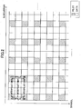
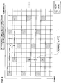
- FIG. 1 shows an example of an arrangement of pilots.
- pilots are mapped in resource elements indicated by hatching.
- resource elements other than the hatched ones data are mapped.
- a resource element here is defined as a radio resource indicated by one subcarrier and one symbol.
- a mobile station apparatus makes transmission channel estimates of resource elements in which pilots are mapped, using an equalization scheme.
- the equalization scheme are Zero Forcing Equalization and MMSE (Minimum Mean Square Error).
- the mobile station apparatus makes transmission channel estimates of resource elements in which no pilots are mapped, based on the result of the estimates of the resource elements with pilots mapped.
- the mobile station apparatus carries out, for example, interpolation in the time (i.e. symbol) direction and the frequency (i.e. subcarrier) direction using the result of the estimates of the resource elements with pilots mapped.
- an allowable delay spread Td is determined by a pilot spacing Nf (Nf is an integer larger than 0) in the frequency direction.
- an allowable Doppler frequency fd is determined by a pilot spacing Nt in the time direction.
- the term "allowable” here refers to being able to perform interpolation.
- the relationships between the allowable delay spread Td and the allowable Doppler frequency fd are expressed by the following relational expressions (1) and (2).
- f0 is a subcarrier frequency spacing
- Ts is a symbol length of OFDM.
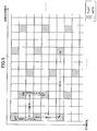
- the relational expressions (1) and (2) if the delay spread Td is large or the Doppler frequency fd is high, the relational expressions (1) and (2) can be satisfied by arranging pilots close to one another to be thus densely spaced. For example, as illustrated in FIG. 2 , the pilot spacings in both the frequency direction and the time direction are made smaller compared to the case of FIG. 1 .
- the pilot spacings can be set larger, for example, if transmission channel characteristics are favorable compared to the case where they are poor.
- the pilot spacings may be dynamically changed between the mobile station apparatus and a base station apparatus in communication with the mobile station apparatus.
- Such a mobile station apparatus is described below with reference to FIG. 3 .
- Downlink signals are transmitted from a base station apparatus.
- pilots are mapped, as illustrated in FIG. 1 .
- pilots are spaced every 6 resource elements apart in the frequency direction and every 4 resource elements apart in the time direction.
- a downlink signal is received by a radio reception unit 2.
- the received downlink signal is input to an FFT (fast Fourier transform) unit 4.
- the FFT unit 4 performs a fast Fourier transformation on the input downlink signal.
- the downlink signal after the fast Fourier transformation is input to a speed measurement unit 12, a transmission channel estimation unit 6 and a compensation unit 8.
- the transmission channel estimation unit 6 performs transmission channel estimation using pilots included in the fast Fourier transformed downlink signal, and then inputs the estimation result to the compensation unit 8.
- the compensation unit 8 makes compensation to the fast Fourier transformed downlink signal based on the estimation result input from the transmission channel estimation unit 6.
- the arrangement of the pilots included in the downlink signal is already known to the mobile station apparatus 1. For example, it may be arranged at the time when the base station apparatus and the mobile station apparatus 1 initiate communications such that the arrangement of pilots included in a first downlink signal transmitted from the base station apparatus is the same as the arrangement of pilots included in a first downlink signal received by the mobile station apparatus 1.
- the arrangement of the pilots included in the downlink signal is known to both the base station apparatus and the mobile station apparatus 1.
- the downlink signal compensated based on the result of the transmission channel estimation is input to a decode unit 10.
- the decode unit 10 decodes the input downlink signal.
- the decoded data are used as received data.
- the speed measurement unit 12 measures the speed of the mobile station apparatus 1 based on the fast Fourier transformed downlink signal.
- the measured speed information is input to a pilot arrangement determination unit 14.
- the pilot arrangement determination unit 14 makes a determination on the arrangement of pilots based on the input speed information. For example, if the speed is fast, the pilot arrangement determination unit 14 may determine the necessity to space the pilots more densely. As has been explained with reference to FIG. 2 , the pilot arrangement determination unit 14 may determine to, for example, space the pilots every 3 resource elements apart in the frequency direction and every 2 resource elements apart in the time direction.
- the pilot arrangement determination unit 14 inputs the determined pilot arrangement to the transmission channel estimation unit 6 and the compensation unit 8.
- the pilot arrangement determination unit 14 also inputs information indicating the determined pilot arrangement to a control channel encode unit 16.
- the control channel encode unit 16 encodes the input information as control information, and inputs the control information to a multiplexing unit 18.
- the multiplexing unit 18 multiplexes, with an uplink data channel, the input control information as an uplink control channel.
- the multiplexing unit 18 then inputs, to a modulation unit 20, an uplink signal into which the uplink control channel and the uplink data channel are multiplexed.
- the modulation unit 20 performs a modulation process on the uplink signal.
- the modulation unit 20 inputs the modulated uplink signal to a radio transmission unit 22.
- the radio transmission unit 22 transmits the input uplink signal to the base station apparatus.
- the base station apparatus arranges pilots in a downlink signal in accordance with the pilot arrangement carried by the uplink control channel. Then, the base station apparatus transmits the downlink signal.
- the mobile station apparatus 1 receives the downlink signal at the radio reception unit 2. Then, the FFT unit 4 performs a fast Fourier transformation on the downlink signal.
- the transmission channel estimation unit 6 performs transmission channel estimation based on the pilot arrangement input from the pilot arrangement determination unit 14.
- the compensation unit 8 makes compensation to the fast Fourier transformed downlink signal based on the estimation result obtained by the transmission channel estimation unit 6.
- the compensated downlink signal is input to the decode unit 10, which then decodes the input downlink signal.
- the decoded data are used as received data.
- the transmission channel estimation unit 6 and the compensation unit 8 (part indicated by a dashed line in FIG. 3 ) are described below with reference to FIG. 4 .
- an FFT output of an OFDM receiver is obtained by the following expression (3).
- d(k,1) which is a transmission symbol, is known to the OFDM receiver.
- Z(k,1) is an additive noise.
- a transmission channel estimate H'(k,1) is obtained by the following expression (4).
- d(k,1) is an example of pilots generated by a pilot generation unit 24 in FIG. 4 .
- a complex division unit 28 calculates the expression (4).
- the pilot generation unit 24 generates pilots, and inputs the generated pilots to the complex division unit 28.
- a pilot pattern selection unit 26 selects pilots from fast Fourier transformed symbols input from the FFT unit 4, and inputs the pilots to the complex division unit 28.
- the complex division unit 28 obtains transmission channel characteristics corresponding to the pilots input from the pilot pattern selection unit 26 based on the pilots input from the pilot generation unit 24, and inputs the obtained transmission channel characteristics of the pilots to a time-direction interpolation unit 30.
- the time-direction interpolation unit 30 performs interpolation in the time direction.
- the time-direction interpolation unit 30 inputs, to a frequency-direction interpolation unit 32, transmission channel characteristics corresponding to the pilots based on which the time-direction interpolation has been performed.
- the frequency-direction interpolation unit 32 performs interpolation in the frequency direction.
- the frequency-direction interpolation unit 32 inputs, to a complex division unit 34, transmission channel estimation results obtained after the frequency-direction interpolation. Based on the transmission channel estimation results, the complex division unit 34 estimates transmitted symbols, which are then input to the decode unit 10.
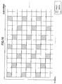
- a scheme referred to as the scattered pilot (SP) scheme is one way to insert pilots.
- SP scattered pilot
- One example of a scattered pilot arrangement is explained with reference to FIG. 5 .
- the tolerance of the delay spread can be increased by, for example, performing the time-direction interpolation first, and then performing the frequency-direction interpolation using the result of the time-direction interpolation.
- the tolerance of the delay spread becomes three times larger.
- US2008075186 A1 refers to an OFDM receiver including OFDM-signal receiving means for receiving an orthogonal frequency division multiplexing (OFDM) signal; channel-characteristic estimating means for estimating a channel characteristic using pilot signals in the OFDM signal received by the OFDM-signal receiving means; and transmission-distortion compensating means for applying, on the basis of the channel characteristic estimated by the channel-characteristic estimating means, processing for compensating for transmission distortion to the OFDM signal received by the OFDM-signal receiving means.
- the channel-characteristic estimating means may include plural kinds of time-direction-channel estimating means used for the estimation of a channel characteristic, and switching control means for switching these estimating means according to a state of a channel.
- pilots are spaced densely, as described above, resource elements allocated to data decrease, which in turn results in a decrease in the throughput. Given this factor, the scattered pilot scheme is applied to thereby increase the tolerance of the delay spread without increasing the number of pilots.
- a mobile station apparatus for receiving a downlink signal including pilots and a transmission channel estimation method, as defined in the claims, are provided.
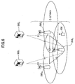
- FIG. 6 An example of a mobile communications system of one embodiment of the present disclosures, which includes a base station apparatus and a mobile station apparatus, is explained below with reference to FIG. 6 .
- Multicarrier transmission is used in the mobile communications system of the present embodiment.
- This mobile communications system transmits user data using shared channels.
- the mobile communications system may transmit user data using common channels.
- the base station apparatus transmits a downlink signal including symbols for transmission channel estimation, based on which the mobile station apparatus performs transmission channel estimation. These symbols may be referred to as pilots, or reference signals.
- One example of mobile communications systems having such characteristics is a LTE (Long Term Evolution) mobile communications system.
- LTE Long Term Evolution
- a LTE mobile communications system is described by way of example; however, the present embodiment may be applied to mobile communications systems other than those supporting LTE, provided that the mobile communications systems have the above-mentioned characteristics.
- the present embodiment may be applied to WiMAX (Worldwide Interoperability for Microwave Access), WLAN (Wireless LAN) mobile communications systems, or digital TV broadcasting.
- WiMAX Worldwide Interoperability for Microwave Access
- WLAN Wireless LAN
- a LTE mobile communications system may also referred to as "Evolved UTRA and UTRAN”.
- the mobile communications system includes one or more mobile station apparatuses (User Equipment, UE) 100 and one or more base station apparatuses (eNode B, eNB) 200 (200 1 , 200 2 and 200 3 in FIG. 6 ). Note that where differentiation is not required, the "mobile station apparatus 100" and “base station apparatus 200" are used for one or more of the mobile station apparatuses and one or more of the base station apparatuses, respectively.
- the mobile communications system also includes MME/S-GWs (Mobility Management Entities/Serving-Gateway) 300 (300 1 and 300 2 in FIG. 6 ) superordinate to the base station apparatuses 200.
- MME/S-GWs Mobility Management Entities/Serving-Gateway
- reference numeral S1 represents an interface between a base station apparatus 100 and a MME/S-GW 300
- a reference numeral X2 is an interface between base station apparatuses 200.
- the base station apparatuses 200 perform call-control operations and wireless-control operations.
- the base station apparatuses 200 also have a RRC (Radio Resource Control) function.
- the base station apparatuses 200 include S1-AP (Application) and X2-AP.
- the MME/S-GWs 300 terminate NAS (Non-Access Stratum) signaling security, and manages mobile station apparatuses in the idle mode and SAE (System Architecture Evolution) bearer resources.
- NAS Non-Access Stratum
- SAE System Architecture Evolution
- the mobile communications system uses, as wireless access schemes, Orthogonal Frequency Division Multiple Access (OFDMA) for the downlink and Single-Carrier Frequency Division Multiple Access (SC-FDMA) for the uplink.
- OFDMA is a scheme in which a frequency range is divided into multiple narrow frequency bands (sub-carriers) and data are transmitted in each frequency band.
- SC-FDMA is a transmission scheme capable of reducing interference between terminals by dividing a frequency range and having multiple terminals transmit in different frequency bands.
- the scattered pilot scheme is applied as a way to insert pilots.
- pilots are assigned to subcarriers in such a manner that pilot-assigned subcarriers in one symbol are different from pilot-assigned subcarriers in the immediately preceding symbol, as described below with reference to FIG. 5 .
- the mobile station apparatus 100 determines the processing order of the time-direction interpolation process and the frequency-direction interpolation process based on the tolerance of the delay spread and/or the tolerance of the Doppler frequency. In other words, the mobile station apparatus 100 of the present embodiment dynamically selects the processing order of the time-direction interpolation process and the frequency-direction interpolation process. If the tolerances of the delay spread and the Doppler frequency are not satisfied even when the two interpolation processes are applied according to the determined processing order, the mobile station apparatus 100 may determine to change the pilot arrangement and reports the arrangement change to the base station apparatus 200. In this case, for example, the mobile station apparatus 100 increases the number of pilots. Thus, by changing the pilot arrangement, it is possible to arrange the pilots efficiently. Also, with the application of the scattered pilot scheme, more symbols and subcarriers can be allocated to data, whereby the throughput can be improved.
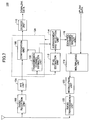
- the mobile station apparatus 100 is described below with reference to FIG. 7 .
- the mobile station apparatus 100 includes a radio reception unit 102.
- the radio reception unit 102 receives a downlink signal transmitted by the base station apparatus 200.
- the radio reception unit 102 inputs the received downlink signal to an FFT unit 104 to be described below.
- the mobile station apparatus 100 includes the FFT unit 104.
- the FFT unit 104 performs a fast Fourier transformation on the downlink signal input from the radio reception unit 102.
- the FFT unit 104 inputs the fast Fourier transformed downlink signal to a transmission channel estimation unit 106, a compensation unit 108 and a Doppler frequency-delay spread (Df-ds) estimation unit 112 to be described below.
- Df-ds Doppler frequency-delay spread
- the mobile station apparatus 100 includes the transmission channel estimation unit 106.
- the transmission channel estimation unit 106 performs transmission channel estimation using pilots included in the fast Fourier transformed downlink signal, and then inputs the estimation result to the compensation unit 108.
- the transmission channel estimation unit 106 also inputs information indicating the pilot arrangement to a pilot arrangement and interpolation method selection unit (hereinafter, referred to simply as "arrangement and selection unit") 114.
- the mobile station apparatus 100 includes the compensation unit 108.
- the compensation unit 108 makes compensation to the fast Fourier transformed downlink signal based on the estimation result input from the transmission channel estimation unit 106.
- the compensation unit 108 inputs the compensated downlink signal to a decode unit 110 to be described below.
- the mobile station apparatus 100 includes the decode unit 110.
- the decode unit 110 decodes the input downlink signal.
- the decoded data are used as received data.
- the mobile station apparatus 100 includes the Df-ds estimation unit 112.
- the Df-ds estimation unit 112 estimates the Doppler frequency and the transmission channel based on the fast Fourier transformed downlink signal. Then, the Df-ds estimation unit 112 inputs the estimated Doppler frequency and delay spread of the transmission channel to the arrangement and selection unit 114.
- the mobile station apparatus 100 includes the arrangement and selection unit 114. Based on the Doppler frequency and delay spread input from the Df-ds estimation unit 112 and the information (indicating the pilot arrangement) input from the transmission channel estimation unit 106, the arrangement and selection unit 114 determines whether the resource element spacing Nf, with which transmission channel characteristics in the frequency direction are obtained when interpolation is performed, and the resource element spacing Nt, with which transmission channel characteristics in the time direction are obtained when interpolation is performed, satisfy relationships that should be satisfied when interpolation is performed.
- a resource element here is defined as a radio resource indicated by one subcarrier and one symbol, as described above.
- f0 is a subcarrier frequency spacing
- Ts is a symbol length of OFDM.
- the resource element spacing Nf is specifically a frequency-direction spacing with which transmission channel characteristics in the frequency direction can be obtained when a predetermined interpolation method is performed based on the information (indicating the pilot arrangement) input from the transmission channel estimation unit 106.
- the resource element spacing Nt is specifically a time-direction spacing with which transmission channel characteristics in the time direction can be obtained when the predetermined interpolation method is performed. If determining that the resource element spacings Nf and Nt satisfy the relational expressions (5) and (6), the arrangement and selection unit 114 determines to use the predetermined interpolation method as originally intended.
- the interpolation method includes, for example, a method of performing interpolation first in the time direction and then performing interpolation in the frequency direction using the result of the time-direction interpolation (hereinafter, referred to as "interpolation method 1"), and a method of performing interpolation first in the frequency direction and then performing interpolation in the time direction using the result of the frequency-direction interpolation ("interpolation method 2").
- interpolation method 1 a method of performing interpolation first in the time direction and then performing interpolation in the frequency direction using the result of the frequency-direction interpolation
- interpolation method 2 a method of performing interpolation first in the frequency direction and then performing interpolation in the time direction using the result of the frequency-direction interpolation
- the arrangement and selection unit 114 determines whether the resource element spacing Nf and/or Nt still satisfy the relational expressions (5) and (6) even if the frequency-direction spacing in which pilots are mapped and/or the time-direction spacing of resource elements in which pilots are mapped is made greater. When determining affirmatively, the arrangement and selection unit 114 determines to increase the frequency-direction spacing and/or the time-direction spacing of resource elements in which pilots are mapped.
- pilots are spaced every 9 resource elements apart in the frequency direction and every 3 resource elements apart in the time direction.
- interpolation is performed first in the time direction, and then performed in the frequency direction using the result of the time-direction interpolation. Accordingly, the resource element spacing Nf becomes 3 while the resource element spacing Nt in the time direction becomes 3.
- the arrangement and selection unit 114 also determines whether the pilots can be more sparsely spaced in the frequency direction and/or the time direction. For example, the arrangement and selection unit 114 may determine whether the pilots can be shifted in the frequency direction in such a manner to increase the resource element spacing Nf by one subcarrier. If the pilots are shifted in such a manner, the pilots are spaced every 12 resource elements apart in the frequency direction and every 3 resource element apart in the time direction, as illustrated in FIG. 8 . In this case, by adopting the interpolation method 1, the resource element spacing Nf in the frequency direction becomes 4 while the resource element spacing Nt in the time direction becomes 3.
- the arrangement and selection unit 114 determines to space the pilots more sparsely in such a manner.
- the arrangement and selection unit 114 spaces the pilots more densely in the frequency direction and/or the time direction.
- the resource element spacings Nf and Nt of the interpolation method 1 or 2 may satisfy the relational expressions (5) and (6).
- the pilots are again spaced more sparsely in the frequency direction and/or the time direction.
- the pilot arrangement is put back to the original one.
- more resource elements can be allocated to data.
- the amount of pilots to be shifted in the frequency direction and/or the time direction may be changed. For example, pilots may be shifted in such a manner to increase the resource element spacing Nf by two subcarriers or more and/or increase the resource element spacing Nt by two symbols or more.
- the arrangement and selection unit 114 determines to adopt the interpolation method 2. According to the interpolation method 2, interpolation is performed first in the frequency direction, and then performed in the time direction based on the result of the frequency-direction interpolation.
- the arrangement and selection unit 114 obtains the resource element spacings Nf and Nt of the interpolation method 2.
- the arrangement and selection unit 114 subsequently determines whether the obtained resource element spacings Nf and Nt satisfy the relational expressions (5) and (6). If the obtained resource element spacings Nf and Nt satisfy the relational expressions (5) and (6), the arrangement and selection unit 114 adopts the interpolation method 2. For example, consider the case in which a downlink signal as illustrated in FIG. 5 is received. In FIG. 5 , the resource element spacings Nf and Nt of the interpolation method 1 are 3 and 3, respectively. On the other hand, the resource element spacings Nf and Nt of the interpolation method 2 are 9 and 1, respectively, as illustrated in FIG. 9 .
- the arrangement and selection unit 114 determines to adopt the interpolation method 2. Note however that the resource element spacing Nf increases due to the interpolation method being adopted, and as a result, the resource element spacings Nf and Nt may not satisfy the relational expression (5). In this case, the arrangement and selection unit 114 may determine to space the pilots more densely.
- the arrangement and selection unit 114 determines whether the pilots can be spaced more densely in the frequency direction and/or the time direction-for example, whether the pilots can be shifted in the frequency direction in such a manner to decrease the resource element spacing Nf by one subcarrier. If the pilots are shifted in such a manner, the pilots are spaced every 6 resource elements apart in the frequency direction and every 3 resource elements apart in the time direction, as illustrated in FIG. 10 . If the resource element spacings Nf and Nt after the pilots are shifted satisfy the relational expressions (5) and (6), the arrangement and selection unit 114 determines to space the pilots more densely in such a manner.
- the arrangement and selection unit 114 inputs information indicating the determined interpolation method to the transmission channel estimation unit 106.
- the arrangement and selection unit 114 also inputs the determined pilot arrangement to the transmission channel estimation unit 106.
- the arrangement and selection unit 114 also inputs the determined pilot arrangement to a control channel encode unit 116.
- the mobile station apparatus 100 includes the control channel encode unit 116.
- the control channel encode unit 116 encodes the input information indicating the pilot arrangement as control information.
- the control channel encode unit 116 then inputs the control information to a multiplexing unit 118 to be described below.
- the mobile station apparatus 100 includes the multiplexing unit 118.
- the multiplexing unit 118 multiplexes, with an uplink data channel, the input control information as an uplink control channel.
- the multiplexing unit 118 then inputs, to a modulation unit 120 to be described below, an uplink signal into which the uplink control channel and the uplink data channel are multiplexed.
- the mobile station apparatus 100 includes the modulation unit 120.
- the modulation unit 120 performs a modulation process on the uplink signal.
- the modulation unit 120 inputs the modulated uplink signal to a radio transmission unit 122 to be described below.
- the mobile station apparatus 100 includes the radio transmission unit 122.
- the radio transmission unit 122 transmits the input uplink signal to the base station apparatus 200.
- the transmission channel estimation unit 106 and the compensation unit 108 are described below with reference to FIG. 11 .
- the transmission channel estimation unit 106 of the present embodiment includes a pilot pattern selection unit 1062, to which the information indicating the pilot arrangement is input from the arrangement and selection unit 114. Based on the input pilot arrangement, the pilot pattern selection unit 1062 selects pilots included in the fast Fourier transformed downlink signal input from the FFT unit 104. The pilot pattern selection unit 1062 inputs the selected pilots to the Df-ds estimation unit 112 and a complex division unit 1066 to be described below. The pilot pattern selection unit 1062 inputs, to a complex division unit 1080 to be described below, data symbols included in the fast Fourier transformed downlink signal input from the FFT unit 104.
- the transmission channel estimation unit 106 includes a pilot generation unit 1064.
- the pilot generation unit 1064 generates pilots, such as d(k, 1), and inputs the generated pilots to the complex division unit 1066.
- the transmission channel estimation unit 106 includes the complex division unit 1066. Based on the pilots input from the pilot generation unit 1064, the complex division unit 1066 estimates transmission channel characteristics corresponding to the pilots input from the pilot pattern selection unit 1062, and then inputs the estimated transmission channel characteristics to a frequency-direction interpolation unit 1068 and a time-direction interpolation unit 1070 to be described below.
- the transmission channel estimation unit 106 includes the frequency-direction interpolation unit 1068.
- the frequency-direction interpolation unit 1068 performs interpolation in the frequency direction on the transmission channel characteristics corresponding to the pilots, which are input from the complex division unit 1066, and then inputs the frequency-direction interpolation result to a selection unit 1072.
- the transmission channel estimation unit 106 includes a time-direction interpolation unit 1070.
- the time-direction interpolation unit 1070 performs interpolation in the time direction on the transmission channel characteristics corresponding to the pilots, which are input from the complex division unit 1066, and then inputs the time-direction interpolation result to the selection unit 1072.
- the transmission channel estimation unit 106 includes the selection unit 1072. Based on an interpolation method input from the arrangement and selection unit 114, the selection unit 1072 selects either one of the frequency-direction interpolation result input from the frequency-direction interpolation unit 1068 and the time-direction interpolation result input from the time-direction interpolation unit 1070. In the case of selecting the frequency-direction interpolation result, the selection unit 1072 inputs the frequency-direction interpolation result to a time-direction interpolation unit 1074 to be described below. In the case of selecting the time-direction interpolation result, the selection unit 1072 inputs the time-direction interpolation result to a time-direction interpolation unit 1076 to be described below.
- the selection unit 1072 selects the time-direction interpolation result.
- the selection unit 1072 selects the frequency-direction interpolation result.
- the transmission channel estimation unit 106 includes the time-direction interpolation unit 1074. Based on the frequency-direction interpolation result input from the selection unit 1072, the time-direction interpolation unit 1074 performs interpolation in the time direction to estimate transmission channel characteristics, and then inputs the estimated transmission channel characteristics to a selection unit 1078.
- the transmission channel estimation unit 106 includes the frequency-direction interpolation unit 1076. Based on the time-direction interpolation result input from the selection unit 1072, the frequency-direction interpolation unit 1076 performs interpolation in the frequency direction to estimate transmission channel characteristics, and then inputs the estimated transmission channel characteristics to the selection unit 1078.
- the transmission channel estimation unit 106 includes the selection unit 1078. Based on the interpolation method input from the arrangement and selection unit 114, the selection unit 1078 selects either one of the estimation result of the transmission channel characteristics input from the time-direction interpolation unit 1074 and the estimation result of the transmission channel characteristics input from the frequency-direction interpolation unit 1076. Then, the selection unit 1078 inputs the selected estimation result to the complex division unit 1080. For example, if the input interpolation method is the interpolation method 1, the selection unit 1078 selects the estimation result of the transmission channel characteristics input from the frequency-direction interpolation unit 1076. On the other hand, if the input interpolation method is the interpolation method 2, the selection unit 1078 selects the estimation result of the transmission channel characteristics input from the time-direction interpolation unit 1074.
- the transmission channel estimation unit 106 includes the complex division unit 1080. Based on the estimation result of the transmission channel characteristics, the complex division unit 1080 estimates transmitted symbols, which are then input to the decode unit 10.
- the base station apparatus 200 transmits a downlink signal (Step S1202).
- the downlink signal includes pilots.
- the arrangement of the pilots to be transmitted may be, for example, predetermined between the mobile station apparatus 100 and the base station apparatus 200.
- the mobile station apparatus 100 estimates the delay spread of the transmission channel (Step S1204).
- the Df-ds estimation unit 112 estimates the delay spread of the transmission channel based on the pilots included in the downlink signal.
- the mobile station apparatus 100 estimates the Doppler frequency based on the downlink signal transmitted by the base station apparatus 200 (Step S1206).
- the Df-ds estimation unit 112 estimates the Doppler frequency based on the pilots included in the downlink signal.
- the mobile station apparatus 100 determines an optimal pilot arrangement according to the above-described method (Step S1208).
- the arrangement and selection unit 114 may change the pilot arrangement if the above relational expressions (5) and (6) are satisfied in neither the interpolation method 1 nor 2.
- the pilot arrangement may be changed by increasing or decreasing the number of pilots. The case where the number of pilots having been reduced at a given time is changed back to the original number is considered as a case of increasing the number of pilots. Also, the case where the number of pilots having been increased at a given time is changed back to the original number is considered as a case of decreasing the number of pilots.
- the mobile station apparatus 100 reports information indicating the determined pilot arrangement to the base station apparatus 200 (Step S1210).
- the control channel encode unit 116 encodes the information indicating the pilot arrangement determined by the arrangement and selection unit 114.
- the encoded information is, as an uplink control channel, multiplexed with uplink data by the multiplexing unit 118.
- the multiplexed information is modulated by the modulation unit 120, and then transmitted by the radio transmission unit 122.
- the base station apparatus 200 maps pilots in the downlink signal in accordance with the pilot arrangement reported by the mobile station apparatus 100 (Step S1212), and then transmits the downlink signal (Step S1214).
- the mobile station apparatus 100 receives the downlink signal transmitted by the base station apparatus 200 based on the pilot arrangement determined in Step S1208 (Step S1216).
- the transmission channel estimation unit 106 estimates the transmission channel based on the pilot arrangement determined by the arrangement and selection unit 114.
- the compensation unit 108 makes compensation to the downlink signal based on the transmission channel estimated by the transmission channel estimation unit 106, and the decode unit 110 then decodes the downlink signal.
- the mobile station apparatus 100 obtains the resource element spacings Nf and Nt with which transmission channel characteristics in the frequency and time directions are obtained when interpolation is performed using the interpolation method 1 (Step S1302). This step may be performed by, for example, the arrangement and selection unit 114.
- the mobile station apparatus 100 determines whether the resource element spacings Nf and Nt of the interpolation method 1 satisfy the relational expressions (5) and (6) (Step S1304). This step may be performed by, for example, the arrangement and selection unit 114.
- Step S1304 the mobile station apparatus 100 determines to adopt the interpolation method 1. Then, the mobile station apparatus 100 determines whether the frequency-direction spacing and/or the time-direction spacing of resource elements in which pilots are mapped can be increased (Step S1306).
- the process of increasing the frequency-direction spacing and/or the time-direction spacing of resource elements in which pilots are mapped may include a process of decreasing the number of the pilots to be mapped.
- the arrangement and selection unit 114 may determine whether the relational expressions (5) and (6) can be still satisfied if the frequency-direction spacing and/or the time-direction spacing of resource elements in which pilots are mapped is increased.
- Step S1306 the mobile station apparatus 100 determines to space the pilots more sparsely in such a manner. This step may be performed by, for example, the arrangement and selection unit 114.
- the mobile station apparatus 100 inputs information indicating the pilot arrangement to the control channel encode unit 116. Then, the information is transmitted to the base station apparatus 200 (Step S1310). On the other hand, if determining that the frequency-direction spacing and/or the time-direction spacing cannot be increased (Step S1306: NO), the mobile station apparatus 100 ends the processing operation without changing the pilot arrangement.
- Step S1304 If determining that the relational expressions (5) and (6) are not satisfied (Step S1304: NO), the mobile station apparatus 100 obtains the resource element spacings Nf and Nt with which transmission channel characteristics in the frequency and time directions are obtained when interpolation is performed using the interpolation method 2 (Step S1312). This step may be performed by, for example, the arrangement and selection unit 114.
- the mobile station apparatus 100 determines the resource element spacings Nf and Nt of the interpolation method 2 satisfy the relational expressions (5) and (6) (Step S1314). This step may be performed by, for example, the arrangement and selection unit 114.
- Step S1314 YES
- the mobile station apparatus 100 determines to adopt the interpolation method 2 (Step S1316).
- Step S1314: NO the mobile station apparatus 100 determines to space the pilots more densely (Step S1318). This step may be performed by, for example, the arrangement and selection unit 114. Spacing the pilots more densely may involve a process of increasing the number of pilots.
- the mobile station apparatus 100 inputs information indicating the pilot arrangement to the control channel encode unit 116. Then, the information is transmitted to the base station apparatus 200 (Step S1320).
- the mobile station apparatus is capable of dynamically selecting the processing order of the time-direction interpolation process and the frequency-direction interpolation process, based on the tolerances of the delay spread and the Doppler frequency.
- the mobile station apparatus 100 determines to rearrange the scattered pilots.
- the rearrangement of the scattered pilots may be achieved by changing in the time-direction spacing and/or the frequency-direction spacing.
- Such rearrangement of the scattered pilots includes a process of increasing or decreasing the frequency-direction spacing and/or the time-direction spacing of resource elements in which pilots are mapped.
- one of the frequency-direction spacing and the time-direction spacing may be increased while the other one may be decreased.
- the rearrangement of the scattered pilots may be achieved by a process of increasing or decreasing the number of pilots to be mapped.
- the mobile station apparatus may be designed not to apply the scattered pilot scheme in the case where an allowable delay spread of the transmission channel and an allowable Doppler frequency cannot be obtained regardless of whether the time-direction interpolation or the frequency-direction interpolation is performed first.
- the present embodiment allows pilots to be arranged efficiently in accordance with the Doppler frequency and the delay spread of the transmission channel, more symbols and subcarriers can be allocated to data, whereby the throughput can be improved.
- the mobile communications system of the second embodiment is described next.
- the mobile communications system of the present embodiment is the same as the mobile communications system described below with reference to FIG. 6 .
- the mobile station apparatus 100 of the present embodiment is the same as the mobile station apparatus 100 described below with reference to FIGs. 7 and 11 .
- the mobile station apparatus 100 of the present embodiment selects the interpolation method based on an estimated Doppler frequency. For example, if the Doppler frequency is equal to or higher than a predetermined threshold, the interpolation method 1 is adopted. If the Doppler frequency is lower than the predetermined threshold, the interpolation method 2 is adopted.
- the threshold may be determined based on the frequency-direction spacing and/or the time-direction spacing of resource elements in which pilots are mapped, the subcarrier frequency spacing f0, and the symbol length of OFDM Ts.
- the selection between the interpolation methods 1 and 2 may be made based on the delay spread of the transmission channel.
- the selection between the interpolation methods 1 and 2 may be made based on both the Doppler frequency and the delay spread of the transmission channel.
- the interpolation method can be selected based on the Doppler frequency and/or the delay spread of the transmission channel, whereby the amount of calculation required to make the selection can be reduced. In other words, it is possible to reduce the processing load of the mobile station apparatus 100.
Description
- The disclosures herein are directed to a radio communications system, and in particular to a mobile station apparatus and a transmission channel estimation method.
- In a radio communications system in which OFDM (Orthogonal Frequency Division Multiplexing) technology, for example, is used in a digital modulation scheme, a transmission channel is estimated using pilot signals (pilots). The pilots are known to both transmitting and receiving ends.
-
FIG. 1 shows an example of an arrangement of pilots. InFIG. 1 , pilots are mapped in resource elements indicated by hatching. In resource elements other than the hatched ones, data are mapped. A resource element here is defined as a radio resource indicated by one subcarrier and one symbol. - A mobile station apparatus makes transmission channel estimates of resource elements in which pilots are mapped, using an equalization scheme. Examples of the equalization scheme are Zero Forcing Equalization and MMSE (Minimum Mean Square Error). Also, the mobile station apparatus makes transmission channel estimates of resource elements in which no pilots are mapped, based on the result of the estimates of the resource elements with pilots mapped. To make estimates of the resource elements with no pilots mapped, the mobile station apparatus carries out, for example, interpolation in the time (i.e. symbol) direction and the frequency (i.e. subcarrier) direction using the result of the estimates of the resource elements with pilots mapped.
- Next is described the case of performing transmission channel estimation by interpolation.
- When a sampling function is used, an allowable delay spread Td is determined by a pilot spacing Nf (Nf is an integer larger than 0) in the frequency direction. Also, an allowable Doppler frequency fd is determined by a pilot spacing Nt in the time direction. The term "allowable" here refers to being able to perform interpolation. The relationships between the allowable delay spread Td and the allowable Doppler frequency fd are expressed by the following relational expressions (1) and (2).


- According to the relational expressions (1) and (2), if the delay spread Td is large or the Doppler frequency fd is high, the relational expressions (1) and (2) can be satisfied by arranging pilots close to one another to be thus densely spaced. For example, as illustrated in
FIG. 2 , the pilot spacings in both the frequency direction and the time direction are made smaller compared to the case ofFIG. 1 . - The pilot spacings can be set larger, for example, if transmission channel characteristics are favorable compared to the case where they are poor. The pilot spacings may be dynamically changed between the mobile station apparatus and a base station apparatus in communication with the mobile station apparatus.
- Such a mobile station apparatus is described below with reference to
FIG. 3 . - Downlink signals are transmitted from a base station apparatus. In the downlink signals, pilots are mapped, as illustrated in
FIG. 1 . In the example ofFIG. 1 , pilots are spaced every 6 resource elements apart in the frequency direction and every 4 resource elements apart in the time direction. - In a
mobile station apparatus 1, a downlink signal is received by aradio reception unit 2. The received downlink signal is input to an FFT (fast Fourier transform)unit 4. TheFFT unit 4 performs a fast Fourier transformation on the input downlink signal. The downlink signal after the fast Fourier transformation is input to aspeed measurement unit 12, a transmissionchannel estimation unit 6 and acompensation unit 8. The transmissionchannel estimation unit 6 performs transmission channel estimation using pilots included in the fast Fourier transformed downlink signal, and then inputs the estimation result to thecompensation unit 8. Thecompensation unit 8 makes compensation to the fast Fourier transformed downlink signal based on the estimation result input from the transmissionchannel estimation unit 6. - The arrangement of the pilots included in the downlink signal is already known to the
mobile station apparatus 1. For example, it may be arranged at the time when the base station apparatus and themobile station apparatus 1 initiate communications such that the arrangement of pilots included in a first downlink signal transmitted from the base station apparatus is the same as the arrangement of pilots included in a first downlink signal received by themobile station apparatus 1. As a result, when communications are established between the base station apparatus and themobile station apparatus 1, the arrangement of the pilots included in the downlink signal is known to both the base station apparatus and themobile station apparatus 1. The downlink signal compensated based on the result of the transmission channel estimation is input to adecode unit 10. Thedecode unit 10 decodes the input downlink signal. The decoded data are used as received data. - On the other hand, the
speed measurement unit 12 measures the speed of themobile station apparatus 1 based on the fast Fourier transformed downlink signal. The measured speed information is input to a pilotarrangement determination unit 14. The pilotarrangement determination unit 14 makes a determination on the arrangement of pilots based on the input speed information. For example, if the speed is fast, the pilotarrangement determination unit 14 may determine the necessity to space the pilots more densely. As has been explained with reference toFIG. 2 , the pilotarrangement determination unit 14 may determine to, for example, space the pilots every 3 resource elements apart in the frequency direction and every 2 resource elements apart in the time direction. The pilotarrangement determination unit 14 inputs the determined pilot arrangement to the transmissionchannel estimation unit 6 and thecompensation unit 8. The pilotarrangement determination unit 14 also inputs information indicating the determined pilot arrangement to a controlchannel encode unit 16. The controlchannel encode unit 16 encodes the input information as control information, and inputs the control information to amultiplexing unit 18. Themultiplexing unit 18 multiplexes, with an uplink data channel, the input control information as an uplink control channel. Themultiplexing unit 18 then inputs, to amodulation unit 20, an uplink signal into which the uplink control channel and the uplink data channel are multiplexed. Themodulation unit 20 performs a modulation process on the uplink signal. Themodulation unit 20 inputs the modulated uplink signal to aradio transmission unit 22. Theradio transmission unit 22 transmits the input uplink signal to the base station apparatus. - The base station apparatus arranges pilots in a downlink signal in accordance with the pilot arrangement carried by the uplink control channel. Then, the base station apparatus transmits the downlink signal.
- The
mobile station apparatus 1 receives the downlink signal at theradio reception unit 2. Then, theFFT unit 4 performs a fast Fourier transformation on the downlink signal. The transmissionchannel estimation unit 6 performs transmission channel estimation based on the pilot arrangement input from the pilotarrangement determination unit 14. Thecompensation unit 8 makes compensation to the fast Fourier transformed downlink signal based on the estimation result obtained by the transmissionchannel estimation unit 6. The compensated downlink signal is input to thedecode unit 10, which then decodes the input downlink signal. The decoded data are used as received data. - The transmission
channel estimation unit 6 and the compensation unit 8 (part indicated by a dashed line inFIG. 3 ) are described below with reference toFIG. 4 . - Assume that an FFT output of an OFDM receiver is obtained by the following expression (3).


- d(k,1) is an example of pilots generated by a
pilot generation unit 24 inFIG. 4 . Acomplex division unit 28 calculates the expression (4). - The
pilot generation unit 24 generates pilots, and inputs the generated pilots to thecomplex division unit 28. A pilotpattern selection unit 26 selects pilots from fast Fourier transformed symbols input from theFFT unit 4, and inputs the pilots to thecomplex division unit 28. Thecomplex division unit 28 obtains transmission channel characteristics corresponding to the pilots input from the pilotpattern selection unit 26 based on the pilots input from thepilot generation unit 24, and inputs the obtained transmission channel characteristics of the pilots to a time-direction interpolation unit 30. The time-direction interpolation unit 30 performs interpolation in the time direction. The time-direction interpolation unit 30 inputs, to a frequency-direction interpolation unit 32, transmission channel characteristics corresponding to the pilots based on which the time-direction interpolation has been performed. The frequency-direction interpolation unit 32 performs interpolation in the frequency direction. The frequency-direction interpolation unit 32 inputs, to acomplex division unit 34, transmission channel estimation results obtained after the frequency-direction interpolation. Based on the transmission channel estimation results, thecomplex division unit 34 estimates transmitted symbols, which are then input to thedecode unit 10. - A scheme referred to as the scattered pilot (SP) scheme is one way to insert pilots. One example of a scattered pilot arrangement is explained with reference to
FIG. 5 . - In the case where the scattered pilot scheme is applied, the tolerance of the delay spread can be increased by, for example, performing the time-direction interpolation first, and then performing the frequency-direction interpolation using the result of the time-direction interpolation. In the case of
FIG. 5 , if the time-direction interpolation is performed first, the resource element spacing Nf, with which transmission channel characteristics in the frequency direction are obtained, can be changed from 9 to 3, and therefore, the tolerance of the delay spread becomes three times larger. -
Japanese Laid-open Patent Application Publication No. 2007-150971 -
US2008075186 A1 refers to an OFDM receiver including OFDM-signal receiving means for receiving an orthogonal frequency division multiplexing (OFDM) signal; channel-characteristic estimating means for estimating a channel characteristic using pilot signals in the OFDM signal received by the OFDM-signal receiving means; and transmission-distortion compensating means for applying, on the basis of the channel characteristic estimated by the channel-characteristic estimating means, processing for compensating for transmission distortion to the OFDM signal received by the OFDM-signal receiving means. The channel-characteristic estimating means may include plural kinds of time-direction-channel estimating means used for the estimation of a channel characteristic, and switching control means for switching these estimating means according to a state of a channel. - MEHMET KEMAL OZDEMIR ET AL published "Channel estimation for wireless OFDM systems" in IEEE COMMUNICATIONS SURVEYS, IEEE, NEW YORK, NY, US,vol. 9, no. 2, 1 April 2007 (2007-04-01), pages 18-48, XP011381247, ISSN: 1553-877X discloses techniques for use in OFDM channel estimation for SISO and MIMO OFDM systems, the techniques being divided into pilot patterns, estimation methods and signal detection methods.
- In the case where pilots are spaced densely, as described above, resource elements allocated to data decrease, which in turn results in a decrease in the throughput. Given this factor, the scattered pilot scheme is applied to thereby increase the tolerance of the delay spread without increasing the number of pilots.
- In this case, however, although the tolerance of the delay spread can be increased, the tolerance of the Doppler frequency is reduced.
- According to aspects of the present invention, a mobile station apparatus for receiving a downlink signal including pilots and a transmission channel estimation method, as defined in the claims, are provided.
- Additional objects and advantages of the embodiment will be set forth in part in the description which follows, and in part will be obvious from the description, or may be learned by practice of the present disclosures. The object and advantages of the present disclosures will be realized and attained by means of the elements and combinations particularly pointed out in the appended claims.
- It is to be understood that both the foregoing general description and the following detailed description are exemplary and explanatory only and are not restrictive of the present disclosures as claimed. The scope of the invention is defined by the claims.
-
-
FIG. 1 shows an example of a pilot arrangement; -
FIG. 2 shows another example of the pilot arrangement; -
FIG. 3 is a partial block diagram of a mobile station apparatus; -
FIG. 4 is a partial block diagram of the mobile station apparatus; -
FIG. 5 shows another example of the pilot arrangement; -
FIG. 6 shows a mobile communications system according to an embodiment; -
FIG. 7 is a partial block diagram of a mobile station apparatus of an embodiment; -
FIG. 8 is an example of a pilot arrangement according to an embodiment; -
FIG. 9 is another example of the pilot arrangement according to an embodiment; -
FIG. 10 is another example of the pilot arrangement according to an embodiment; -
FIG. 11 is a partial block diagram of the mobile station apparatus according to an embodiment; -
FIG. 12 is a flowchart showing an operation of the mobile communications system according to an embodiment; and -
FIG. 13 is a flowchart showing an operation of the mobile station apparatus according to an embodiment. - Embodiments that describe the best mode for carrying out the present disclosures are explained next with reference to the drawings.
- In all drawings used to describe the embodiments, the same reference numerals are given to components having the same functions, and their explanations are omitted.
- An example of a mobile communications system of one embodiment of the present disclosures, which includes a base station apparatus and a mobile station apparatus, is explained below with reference to
FIG. 6 . - Multicarrier transmission is used in the mobile communications system of the present embodiment. This mobile communications system transmits user data using shared channels. Alternatively, the mobile communications system may transmit user data using common channels. In the mobile communications system, the base station apparatus transmits a downlink signal including symbols for transmission channel estimation, based on which the mobile station apparatus performs transmission channel estimation. These symbols may be referred to as pilots, or reference signals. One example of mobile communications systems having such characteristics is a LTE (Long Term Evolution) mobile communications system. In the present embodiment, a LTE mobile communications system is described by way of example; however, the present embodiment may be applied to mobile communications systems other than those supporting LTE, provided that the mobile communications systems have the above-mentioned characteristics. For example, the present embodiment may be applied to WiMAX (Worldwide Interoperability for Microwave Access), WLAN (Wireless LAN) mobile communications systems, or digital TV broadcasting. A LTE mobile communications system may also referred to as "Evolved UTRA and UTRAN".
- The mobile communications system according to the present embodiment includes one or more mobile station apparatuses (User Equipment, UE) 100 and one or more base station apparatuses (eNode B, eNB) 200 (2001, 2002 and 2003 in
FIG. 6 ). Note that where differentiation is not required, the "mobile station apparatus 100" and "base station apparatus 200" are used for one or more of the mobile station apparatuses and one or more of the base station apparatuses, respectively. The mobile communications system also includes MME/S-GWs (Mobility Management Entities/Serving-Gateway) 300 (3001 and 3002 inFIG. 6 ) superordinate to the base station apparatuses 200. - In
FIG. 6 , reference numeral S1 represents an interface between abase station apparatus 100 and a MME/S-GW 300, and a reference numeral X2 is an interface between base station apparatuses 200. - The base station apparatuses 200 perform call-control operations and wireless-control operations. The base station apparatuses 200 also have a RRC (Radio Resource Control) function. The base station apparatuses 200 include S1-AP (Application) and X2-AP.
- The MME/S-
GWs 300 terminate NAS (Non-Access Stratum) signaling security, and manages mobile station apparatuses in the idle mode and SAE (System Architecture Evolution) bearer resources. - The mobile communications system uses, as wireless access schemes, Orthogonal Frequency Division Multiple Access (OFDMA) for the downlink and Single-Carrier Frequency Division Multiple Access (SC-FDMA) for the uplink. OFDMA is a scheme in which a frequency range is divided into multiple narrow frequency bands (sub-carriers) and data are transmitted in each frequency band. SC-FDMA is a transmission scheme capable of reducing interference between terminals by dividing a frequency range and having multiple terminals transmit in different frequency bands.
- In the mobile communications system according to the present embodiment, the scattered pilot scheme is applied as a way to insert pilots. According to the scattered pilot scheme, pilots are assigned to subcarriers in such a manner that pilot-assigned subcarriers in one symbol are different from pilot-assigned subcarriers in the immediately preceding symbol, as described below with reference to
FIG. 5 . - In the mobile communications system according to the present embodiment, the
mobile station apparatus 100 determines the processing order of the time-direction interpolation process and the frequency-direction interpolation process based on the tolerance of the delay spread and/or the tolerance of the Doppler frequency. In other words, themobile station apparatus 100 of the present embodiment dynamically selects the processing order of the time-direction interpolation process and the frequency-direction interpolation process. If the tolerances of the delay spread and the Doppler frequency are not satisfied even when the two interpolation processes are applied according to the determined processing order, themobile station apparatus 100 may determine to change the pilot arrangement and reports the arrangement change to the base station apparatus 200. In this case, for example, themobile station apparatus 100 increases the number of pilots. Thus, by changing the pilot arrangement, it is possible to arrange the pilots efficiently. Also, with the application of the scattered pilot scheme, more symbols and subcarriers can be allocated to data, whereby the throughput can be improved. - The
mobile station apparatus 100 is described below with reference toFIG. 7 . - The
mobile station apparatus 100 includes aradio reception unit 102. Theradio reception unit 102 receives a downlink signal transmitted by the base station apparatus 200. Theradio reception unit 102 inputs the received downlink signal to anFFT unit 104 to be described below. - The
mobile station apparatus 100 includes theFFT unit 104. TheFFT unit 104 performs a fast Fourier transformation on the downlink signal input from theradio reception unit 102. TheFFT unit 104 inputs the fast Fourier transformed downlink signal to a transmissionchannel estimation unit 106, acompensation unit 108 and a Doppler frequency-delay spread (Df-ds)estimation unit 112 to be described below. - The
mobile station apparatus 100 includes the transmissionchannel estimation unit 106. The transmissionchannel estimation unit 106 performs transmission channel estimation using pilots included in the fast Fourier transformed downlink signal, and then inputs the estimation result to thecompensation unit 108. The transmissionchannel estimation unit 106 also inputs information indicating the pilot arrangement to a pilot arrangement and interpolation method selection unit (hereinafter, referred to simply as "arrangement and selection unit") 114. - The
mobile station apparatus 100 includes thecompensation unit 108. Thecompensation unit 108 makes compensation to the fast Fourier transformed downlink signal based on the estimation result input from the transmissionchannel estimation unit 106. Thecompensation unit 108 inputs the compensated downlink signal to adecode unit 110 to be described below. - The
mobile station apparatus 100 includes thedecode unit 110. Thedecode unit 110 decodes the input downlink signal. The decoded data are used as received data. - The
mobile station apparatus 100 includes the Df-ds estimation unit 112. The Df-ds estimation unit 112 estimates the Doppler frequency and the transmission channel based on the fast Fourier transformed downlink signal. Then, the Df-ds estimation unit 112 inputs the estimated Doppler frequency and delay spread of the transmission channel to the arrangement and selection unit 114. - The
mobile station apparatus 100 includes the arrangement and selection unit 114. Based on the Doppler frequency and delay spread input from the Df-ds estimation unit 112 and the information (indicating the pilot arrangement) input from the transmissionchannel estimation unit 106, the arrangement and selection unit 114 determines whether the resource element spacing Nf, with which transmission channel characteristics in the frequency direction are obtained when interpolation is performed, and the resource element spacing Nt, with which transmission channel characteristics in the time direction are obtained when interpolation is performed, satisfy relationships that should be satisfied when interpolation is performed. Note that a resource element here is defined as a radio resource indicated by one subcarrier and one symbol, as described above. - The relationships that should be satisfied when interpolation is performed are expressed by the following expressions (5) and (6).


- In the above determination made by the arrangement and selection unit 114, the resource element spacing Nf is specifically a frequency-direction spacing with which transmission channel characteristics in the frequency direction can be obtained when a predetermined interpolation method is performed based on the information (indicating the pilot arrangement) input from the transmission
channel estimation unit 106. Also, the resource element spacing Nt is specifically a time-direction spacing with which transmission channel characteristics in the time direction can be obtained when the predetermined interpolation method is performed. If determining that the resource element spacings Nf and Nt satisfy the relational expressions (5) and (6), the arrangement and selection unit 114 determines to use the predetermined interpolation method as originally intended. The interpolation method includes, for example, a method of performing interpolation first in the time direction and then performing interpolation in the frequency direction using the result of the time-direction interpolation (hereinafter, referred to as "interpolation method 1"), and a method of performing interpolation first in the frequency direction and then performing interpolation in the time direction using the result of the frequency-direction interpolation ("interpolation method 2"). The present embodiment describes the case in which theinterpolation method 1 is applied as the predetermined interpolation method; however, the following procedure is the same if theinterpolation method 2 is adopted as the predetermined interpolation method. - In the case where the
interpolation method 1 is adopted, the arrangement and selection unit 114 determines whether the resource element spacing Nf and/or Nt still satisfy the relational expressions (5) and (6) even if the frequency-direction spacing in which pilots are mapped and/or the time-direction spacing of resource elements in which pilots are mapped is made greater. When determining affirmatively, the arrangement and selection unit 114 determines to increase the frequency-direction spacing and/or the time-direction spacing of resource elements in which pilots are mapped. - For example, consider the case in which a downlink signal as illustrated in
FIG. 5 is received. InFIG. 5 , pilots are spaced every 9 resource elements apart in the frequency direction and every 3 resource elements apart in the time direction. In this case, by applying theinterpolation method 1, interpolation is performed first in the time direction, and then performed in the frequency direction using the result of the time-direction interpolation. Accordingly, the resource element spacing Nf becomes 3 while the resource element spacing Nt in the time direction becomes 3. - The arrangement and selection unit 114 also determines whether the pilots can be more sparsely spaced in the frequency direction and/or the time direction. For example, the arrangement and selection unit 114 may determine whether the pilots can be shifted in the frequency direction in such a manner to increase the resource element spacing Nf by one subcarrier. If the pilots are shifted in such a manner, the pilots are spaced every 12 resource elements apart in the frequency direction and every 3 resource element apart in the time direction, as illustrated in
FIG. 8 . In this case, by adopting theinterpolation method 1, the resource element spacing Nf in the frequency direction becomes 4 while the resource element spacing Nt in the time direction becomes 3. At this point, if the resource element spacings Nf and Nt still satisfy the relational expressions (5) and (6), the arrangement and selection unit 114 determines to space the pilots more sparsely in such a manner. On the other hand, if the resource element spacings Nf and Nt of theinterpolation method interpolation method - When determining that the resource element spacings Nf and Nt of the predetermined interpolation method, i.e. the
interpolation method 1, satisfy only the relational expression (5), the arrangement and selection unit 114 determines to adopt theinterpolation method 2. According to theinterpolation method 2, interpolation is performed first in the frequency direction, and then performed in the time direction based on the result of the frequency-direction interpolation. - Then, the arrangement and selection unit 114 obtains the resource element spacings Nf and Nt of the
interpolation method 2. The arrangement and selection unit 114 subsequently determines whether the obtained resource element spacings Nf and Nt satisfy the relational expressions (5) and (6). If the obtained resource element spacings Nf and Nt satisfy the relational expressions (5) and (6), the arrangement and selection unit 114 adopts theinterpolation method 2. For example, consider the case in which a downlink signal as illustrated inFIG. 5 is received. InFIG. 5 , the resource element spacings Nf and Nt of theinterpolation method 1 are 3 and 3, respectively. On the other hand, the resource element spacings Nf and Nt of theinterpolation method 2 are 9 and 1, respectively, as illustrated inFIG. 9 . If determining that Nt = 1 and Nf = 9 satisfy the relational expressions (5) and (6), the arrangement and selection unit 114 determines to adopt theinterpolation method 2. Note however that the resource element spacing Nf increases due to the interpolation method being adopted, and as a result, the resource element spacings Nf and Nt may not satisfy the relational expression (5). In this case, the arrangement and selection unit 114 may determine to space the pilots more densely. - For example, the arrangement and selection unit 114 determines whether the pilots can be spaced more densely in the frequency direction and/or the time direction-for example, whether the pilots can be shifted in the frequency direction in such a manner to decrease the resource element spacing Nf by one subcarrier. If the pilots are shifted in such a manner, the pilots are spaced every 6 resource elements apart in the frequency direction and every 3 resource elements apart in the time direction, as illustrated in
FIG. 10 . If the resource element spacings Nf and Nt after the pilots are shifted satisfy the relational expressions (5) and (6), the arrangement and selection unit 114 determines to space the pilots more densely in such a manner. - Then, the arrangement and selection unit 114 inputs information indicating the determined interpolation method to the transmission
channel estimation unit 106. The arrangement and selection unit 114 also inputs the determined pilot arrangement to the transmissionchannel estimation unit 106. The arrangement and selection unit 114 also inputs the determined pilot arrangement to a control channel encodeunit 116. - The
mobile station apparatus 100 includes the control channel encodeunit 116. The control channel encodeunit 116 encodes the input information indicating the pilot arrangement as control information. The control channel encodeunit 116 then inputs the control information to amultiplexing unit 118 to be described below. - The
mobile station apparatus 100 includes themultiplexing unit 118. Themultiplexing unit 118 multiplexes, with an uplink data channel, the input control information as an uplink control channel. Themultiplexing unit 118 then inputs, to amodulation unit 120 to be described below, an uplink signal into which the uplink control channel and the uplink data channel are multiplexed. - The
mobile station apparatus 100 includes themodulation unit 120. Themodulation unit 120 performs a modulation process on the uplink signal. Themodulation unit 120 inputs the modulated uplink signal to aradio transmission unit 122 to be described below. - The
mobile station apparatus 100 includes theradio transmission unit 122. Theradio transmission unit 122 transmits the input uplink signal to the base station apparatus 200. - The transmission
channel estimation unit 106 and the compensation unit 108 (dashed-line part indicated by areference numeral 124 inFIG. 7 ) are described below with reference toFIG. 11 . - Assume that an FFT output of an OFDM receiver is obtained by the above expression (3). In this case, the transmission channel estimate H' (k, 1) is obtained by the above expression (4).
- The transmission
channel estimation unit 106 of the present embodiment includes a pilotpattern selection unit 1062, to which the information indicating the pilot arrangement is input from the arrangement and selection unit 114. Based on the input pilot arrangement, the pilotpattern selection unit 1062 selects pilots included in the fast Fourier transformed downlink signal input from theFFT unit 104. The pilotpattern selection unit 1062 inputs the selected pilots to the Df-ds estimation unit 112 and acomplex division unit 1066 to be described below. The pilotpattern selection unit 1062 inputs, to acomplex division unit 1080 to be described below, data symbols included in the fast Fourier transformed downlink signal input from theFFT unit 104. - The transmission
channel estimation unit 106 includes apilot generation unit 1064. Thepilot generation unit 1064 generates pilots, such as d(k, 1), and inputs the generated pilots to thecomplex division unit 1066. - The transmission
channel estimation unit 106 includes thecomplex division unit 1066. Based on the pilots input from thepilot generation unit 1064, thecomplex division unit 1066 estimates transmission channel characteristics corresponding to the pilots input from the pilotpattern selection unit 1062, and then inputs the estimated transmission channel characteristics to a frequency-direction interpolation unit 1068 and a time-direction interpolation unit 1070 to be described below. - The transmission
channel estimation unit 106 includes the frequency-direction interpolation unit 1068. The frequency-direction interpolation unit 1068 performs interpolation in the frequency direction on the transmission channel characteristics corresponding to the pilots, which are input from thecomplex division unit 1066, and then inputs the frequency-direction interpolation result to aselection unit 1072. - The transmission
channel estimation unit 106 includes a time-direction interpolation unit 1070. The time-direction interpolation unit 1070 performs interpolation in the time direction on the transmission channel characteristics corresponding to the pilots, which are input from thecomplex division unit 1066, and then inputs the time-direction interpolation result to theselection unit 1072. - The transmission
channel estimation unit 106 includes theselection unit 1072. Based on an interpolation method input from the arrangement and selection unit 114, theselection unit 1072 selects either one of the frequency-direction interpolation result input from the frequency-direction interpolation unit 1068 and the time-direction interpolation result input from the time-direction interpolation unit 1070. In the case of selecting the frequency-direction interpolation result, theselection unit 1072 inputs the frequency-direction interpolation result to a time-direction interpolation unit 1074 to be described below. In the case of selecting the time-direction interpolation result, theselection unit 1072 inputs the time-direction interpolation result to a time-direction interpolation unit 1076 to be described below. For example, if the input interpolation method is theinterpolation method 1, theselection unit 1072 selects the time-direction interpolation result. On the other hand, if the input interpolation method is theinterpolation method 2, theselection unit 1072 selects the frequency-direction interpolation result. - The transmission
channel estimation unit 106 includes the time-direction interpolation unit 1074. Based on the frequency-direction interpolation result input from theselection unit 1072, the time-direction interpolation unit 1074 performs interpolation in the time direction to estimate transmission channel characteristics, and then inputs the estimated transmission channel characteristics to aselection unit 1078. - The transmission
channel estimation unit 106 includes the frequency-direction interpolation unit 1076. Based on the time-direction interpolation result input from theselection unit 1072, the frequency-direction interpolation unit 1076 performs interpolation in the frequency direction to estimate transmission channel characteristics, and then inputs the estimated transmission channel characteristics to theselection unit 1078. - The transmission
channel estimation unit 106 includes theselection unit 1078. Based on the interpolation method input from the arrangement and selection unit 114, theselection unit 1078 selects either one of the estimation result of the transmission channel characteristics input from the time-direction interpolation unit 1074 and the estimation result of the transmission channel characteristics input from the frequency-direction interpolation unit 1076. Then, theselection unit 1078 inputs the selected estimation result to thecomplex division unit 1080. For example, if the input interpolation method is theinterpolation method 1, theselection unit 1078 selects the estimation result of the transmission channel characteristics input from the frequency-direction interpolation unit 1076. On the other hand, if the input interpolation method is theinterpolation method 2, theselection unit 1078 selects the estimation result of the transmission channel characteristics input from the time-direction interpolation unit 1074. - The transmission
channel estimation unit 106 includes thecomplex division unit 1080. Based on the estimation result of the transmission channel characteristics, thecomplex division unit 1080 estimates transmitted symbols, which are then input to thedecode unit 10. - The operation of the mobile communications system of the present embodiment is described below with reference to
FIG. 12 . - The base station apparatus 200 transmits a downlink signal (Step S1202). The downlink signal includes pilots. The arrangement of the pilots to be transmitted may be, for example, predetermined between the
mobile station apparatus 100 and the base station apparatus 200. - Based on the downlink signal transmitted by the base station apparatus 200, the
mobile station apparatus 100 estimates the delay spread of the transmission channel (Step S1204). For example, the Df-ds estimation unit 112 estimates the delay spread of the transmission channel based on the pilots included in the downlink signal. - The
mobile station apparatus 100 estimates the Doppler frequency based on the downlink signal transmitted by the base station apparatus 200 (Step S1206). For example, the Df-ds estimation unit 112 estimates the Doppler frequency based on the pilots included in the downlink signal. - Based on the estimated delay spread and Doppler frequency, the
mobile station apparatus 100 determines an optimal pilot arrangement according to the above-described method (Step S1208). For example, the arrangement and selection unit 114 may change the pilot arrangement if the above relational expressions (5) and (6) are satisfied in neither theinterpolation method 1 nor 2. The pilot arrangement may be changed by increasing or decreasing the number of pilots. The case where the number of pilots having been reduced at a given time is changed back to the original number is considered as a case of increasing the number of pilots. Also, the case where the number of pilots having been increased at a given time is changed back to the original number is considered as a case of decreasing the number of pilots. - The
mobile station apparatus 100 reports information indicating the determined pilot arrangement to the base station apparatus 200 (Step S1210). For example, the control channel encodeunit 116 encodes the information indicating the pilot arrangement determined by the arrangement and selection unit 114. The encoded information is, as an uplink control channel, multiplexed with uplink data by themultiplexing unit 118. The multiplexed information is modulated by themodulation unit 120, and then transmitted by theradio transmission unit 122. - The base station apparatus 200 maps pilots in the downlink signal in accordance with the pilot arrangement reported by the mobile station apparatus 100 (Step S1212), and then transmits the downlink signal (Step S1214).
- The
mobile station apparatus 100 receives the downlink signal transmitted by the base station apparatus 200 based on the pilot arrangement determined in Step S1208 (Step S1216). For example, the transmissionchannel estimation unit 106 estimates the transmission channel based on the pilot arrangement determined by the arrangement and selection unit 114. Thecompensation unit 108 makes compensation to the downlink signal based on the transmission channel estimated by the transmissionchannel estimation unit 106, and thedecode unit 110 then decodes the downlink signal. - The operation of the
mobile station apparatus 100 of the present embodiment is described below with reference toFIG. 13 . - Based on the pilot arrangement, the
mobile station apparatus 100 obtains the resource element spacings Nf and Nt with which transmission channel characteristics in the frequency and time directions are obtained when interpolation is performed using the interpolation method 1 (Step S1302). This step may be performed by, for example, the arrangement and selection unit 114. - Based on the estimated Doppler frequency and delay spread of the transmission channel, the
mobile station apparatus 100 determines whether the resource element spacings Nf and Nt of theinterpolation method 1 satisfy the relational expressions (5) and (6) (Step S1304). This step may be performed by, for example, the arrangement and selection unit 114. - If determining that the relational expressions (5) and (6) are satisfied (Step S1304: YES), the
mobile station apparatus 100 determines to adopt theinterpolation method 1. Then, themobile station apparatus 100 determines whether the frequency-direction spacing and/or the time-direction spacing of resource elements in which pilots are mapped can be increased (Step S1306). The process of increasing the frequency-direction spacing and/or the time-direction spacing of resource elements in which pilots are mapped may include a process of decreasing the number of the pilots to be mapped. For example, the arrangement and selection unit 114 may determine whether the relational expressions (5) and (6) can be still satisfied if the frequency-direction spacing and/or the time-direction spacing of resource elements in which pilots are mapped is increased. - If determining that the frequency-direction spacing and/or the time-direction spacing can be increased (Step S1306: YES), the
mobile station apparatus 100 determines to space the pilots more sparsely in such a manner (Step S1308). This step may be performed by, for example, the arrangement and selection unit 114. - The
mobile station apparatus 100 inputs information indicating the pilot arrangement to the control channel encodeunit 116. Then, the information is transmitted to the base station apparatus 200 (Step S1310). On the other hand, if determining that the frequency-direction spacing and/or the time-direction spacing cannot be increased (Step S1306: NO), themobile station apparatus 100 ends the processing operation without changing the pilot arrangement. - If determining that the relational expressions (5) and (6) are not satisfied (Step S1304: NO), the
mobile station apparatus 100 obtains the resource element spacings Nf and Nt with which transmission channel characteristics in the frequency and time directions are obtained when interpolation is performed using the interpolation method 2 (Step S1312). This step may be performed by, for example, the arrangement and selection unit 114. - The
mobile station apparatus 100 determines the resource element spacings Nf and Nt of theinterpolation method 2 satisfy the relational expressions (5) and (6) (Step S1314). This step may be performed by, for example, the arrangement and selection unit 114. - If determining that the relational expressions (5) and (6) are satisfied (Step S1314: YES), the
mobile station apparatus 100 determines to adopt the interpolation method 2 (Step S1316). On the other hand, if determining that the relational expressions (5) and (6) are not satisfied (Step S1314: NO), themobile station apparatus 100 determines to space the pilots more densely (Step S1318). This step may be performed by, for example, the arrangement and selection unit 114. Spacing the pilots more densely may involve a process of increasing the number of pilots. - The
mobile station apparatus 100 inputs information indicating the pilot arrangement to the control channel encodeunit 116. Then, the information is transmitted to the base station apparatus 200 (Step S1320). - According to the present embodiment, in the mobile communications system to which the scattered pilot scheme is applied, the mobile station apparatus is capable of dynamically selecting the processing order of the time-direction interpolation process and the frequency-direction interpolation process, based on the tolerances of the delay spread and the Doppler frequency. Herewith, it is possible to change the pilot arrangement dynamically and efficiently.
- In the case where an allowable delay spread of the transmission channel and an allowable Doppler frequency cannot be obtained regardless of whether the time-direction interpolation or the frequency-direction interpolation is performed first, the
mobile station apparatus 100 determines to rearrange the scattered pilots. The rearrangement of the scattered pilots may be achieved by changing in the time-direction spacing and/or the frequency-direction spacing. Such rearrangement of the scattered pilots includes a process of increasing or decreasing the frequency-direction spacing and/or the time-direction spacing of resource elements in which pilots are mapped. In addition, one of the frequency-direction spacing and the time-direction spacing may be increased while the other one may be decreased. In addition, the rearrangement of the scattered pilots may be achieved by a process of increasing or decreasing the number of pilots to be mapped. Herewith, it is possible to change the pilot arrangement dynamically and efficiently. Also, the mobile station apparatus may be designed not to apply the scattered pilot scheme in the case where an allowable delay spread of the transmission channel and an allowable Doppler frequency cannot be obtained regardless of whether the time-direction interpolation or the frequency-direction interpolation is performed first. - Since the present embodiment allows pilots to be arranged efficiently in accordance with the Doppler frequency and the delay spread of the transmission channel, more symbols and subcarriers can be allocated to data, whereby the throughput can be improved.
- The mobile communications system of the second embodiment is described next. The mobile communications system of the present embodiment is the same as the mobile communications system described below with reference to
FIG. 6 . - The
mobile station apparatus 100 of the present embodiment is the same as themobile station apparatus 100 described below with reference toFIGs. 7 and11 . - The
mobile station apparatus 100 of the present embodiment selects the interpolation method based on an estimated Doppler frequency. For example, if the Doppler frequency is equal to or higher than a predetermined threshold, theinterpolation method 1 is adopted. If the Doppler frequency is lower than the predetermined threshold, theinterpolation method 2 is adopted. The threshold may be determined based on the frequency-direction spacing and/or the time-direction spacing of resource elements in which pilots are mapped, the subcarrier frequency spacing f0, and the symbol length of OFDM Ts. - In the above-described embodiment, the selection between the
interpolation methods - In the above-described embodiment, the selection between the
interpolation methods - According to the present embodiment, the interpolation method can be selected based on the Doppler frequency and/or the delay spread of the transmission channel, whereby the amount of calculation required to make the selection can be reduced. In other words, it is possible to reduce the processing load of the
mobile station apparatus 100. - The pilot arrangements illustrated in the above embodiments are merely examples, and they can be changed accordingly.
- All examples and conditional language used herein are intended for pedagogical purposes to aid the reader in understanding the principles of the present disclosures and the concepts contributed by the inventor to furthering the art, and are to be construed as being without limitation to such specifically recited examples and conditions, nor does the organization of such examples in the specification relate to a showing of the superiority or inferiority of the present disclosures. Although the embodiments of the present disclosures have been described in detail, it should be understood that various changes, substitutions, and alterations could be made hereto without departing from the scope of the present disclosures.
Claims (10)
- A mobile station apparatus (100) for receiving a downlink signal including pilots, comprising:a first estimation unit (112) configured to estimate a delay spread of a transmission channel and a Doppler frequency based on the downlink signal;a determination unit (114) configured to determine an interpolation method to be applied to the pilots by determining, based on the delay spread and the Doppler frequency, whether to use a predetermined interpolation method as the interpolation method or to change the predetermined interpolation method to another interpolation method and use said another interpolation method as the interpolation method; anda second estimation unit (106) configured to perform interpolation using the determined interpolation method to estimate the transmission channel,wherein the interpolation method is one of a first interpolation method and a second interpolation method,the first interpolation method performing time-direction interpolation and then performing frequency-direction interpolation using a result of the time-direction interpolation, andthe second interpolation method performing frequency-direction interpolation and then performing time-direction interpolation using a result of the frequency-direction interpolation,wherein the determination unit is further configured:to obtain a frequency-direction resource element spacing, with which transmission channel characteristics in a frequency direction are obtained when one of the first and the second interpolation methods is applied, and a time-direction resource element spacing, with which transmission channel characteristics in a time direction are obtained when the one of the first and the second interpolation methods is applied, and characterized by being configured to determine the one of the first and the second interpolation methods as the interpolation method to be applied if the frequency-direction resource element spacing and the time-direction resource element spacing satisfy a condition that allows the interpolation to be performed,wherein, if the frequency-direction resource element spacing and the time-direction resource element spacing do not satisfy the condition that allows the interpolation to be performed, the determination unit is further configured to obtain a second frequency-direction resource element spacing, with which transmission channel characteristics in the frequency direction are obtained if the other one of the first and the second interpolation methods is applied, and a second time-direction resource element spacing, with which transmission channel characteristics in the time direction are obtained if the other one of the first and the second interpolation methods is applied; and the determination unit is further configured to determine the other one of the first and the second interpolation methods as the interpolation method to be applied if the second frequency direction resource element spacing and the second time-direction resource element spacing satisfy the condition,wherein the condition that allows the interpolation to be performed is defined by


- The mobile station apparatus as claimed in claim 1, wherein the pilots are assigned to subcarriers in such a manner that pilot-assigned subcarriers in one symbol are different from pilot-assigned subcarriers in a symbol immediately preceding the one symbol.
- The mobile station apparatus as claimed in claim 1, wherein the determination unit is further configured
to obtain the frequency-direction resource element spacing and the time-direction resource element spacing for a case where the pilots included in the downlink signal are spaced more sparsely, and
to determine to space the pilots more sparsely if the frequency-direction resource element spacing and the time-direction resource element spacing still satisfy the condition. - The mobile station apparatus as claimed in claim 1, wherein the determination unit is further configured to determine to change an arrangement of the pilots if the second frequency-direction resource element spacing and the second time-direction resource element spacing do not satisfy the condition.
- The mobile station apparatus as claimed in claim 4, wherein the change of the arrangement of the pilots is to space the pilots more densely.
- A transmission channel estimation method comprising the steps of:estimating a delay spread of a transmission channel and a Doppler frequency based on a downlink signal including pilots;determining an interpolation method to be performed on the pilots by determining, based on the delay spread and the Doppler frequency, whether to use a predetermined interpolation method as the interpolation method or to change the predetermined interpolation method to another interpolation method and use said another interpolation method as the interpolation method; andperforming interpolation by the determined interpolation method to estimate the transmission channel,wherein the interpolation method is one of a first interpolation method and a second interpolation method,the first interpolation method performing time-direction interpolation and then performing frequency-direction interpolation using a result of the time-direction interpolation, andthe second interpolation method performing frequency-direction interpolation and then performing time-direction interpolation using a result of the frequency-direction interpolation,wherein the determining further comprises:obtaining a frequency-direction resource element spacing, with which transmission channel characteristics in a frequency direction are obtained when one of the first and the second interpolation methods is applied, and a time-direction resource element spacing, with which transmission channel characteristics in a time direction are obtained when the one of the first and the second interpolation methods is applied, and characterized by determining the one of the first and the second interpolation methods as the interpolation method to be applied if the frequency-direction resource element spacing and the time-direction resource element spacing satisfy a condition that allows the interpolation to be performed,wherein, if the frequency-direction resource element spacing and the time-direction resource element spacing do not satisfy the condition that allows the interpolation to be performed, the determination further comprises obtaining a second frequency-direction resource element spacing, with which transmission channel characteristics in the frequency direction are obtained if the other one of the first and the second interpolation methods is applied, and a second time-direction resource element spacing, with which transmission channel characteristics in the time direction are obtained if the other one of the first and the second interpolation methods is applied; and determining the other one of the first and the second interpolation methods as the interpolation method to be applied if the second frequency direction resource element spacing and the second time-direction resource element spacing satisfy the condition,wherein the condition that allows the interpolation to be performed is defined by


- The transmission channel estimation method as claimed in claim 6, wherein the pilots are assigned to subcarriers in such a manner that pilot-assigned subcarriers in one symbol are different from pilot-assigned subcarriers in a symbol immediately preceding the one symbol.
- The transmission channel estimation method as claimed in claim 6, wherein the method further comprises
obtaining the frequency-direction resource element spacing and the time-direction resource element spacing for a case where the pilots included in the downlink signal are spaced more sparsely, and
determining to space the pilots more sparsely if the frequency-direction resource element spacing and the time-direction resource element spacing still satisfy the condition. - The transmission channel estimation method as claimed in claim 6, wherein the method further comprises determining to change an arrangement of the pilots if the second frequency-direction resource element spacing and the second time-direction resource element spacing do not satisfy the condition.
- The transmission channel estimation method as claimed in claim 9, wherein the change of the arrangement of the pilots is to space the pilots more densely.
Applications Claiming Priority (1)
| Application Number | Priority Date | Filing Date | Title |
|---|---|---|---|
| JP2008106572A JP5169423B2 (en) | 2008-04-16 | 2008-04-16 | Mobile station apparatus and transmission path estimation method |
Publications (3)
| Publication Number | Publication Date |
|---|---|
| EP2111004A2 EP2111004A2 (en) | 2009-10-21 |
| EP2111004A3 EP2111004A3 (en) | 2013-07-03 |
| EP2111004B1 true EP2111004B1 (en) | 2016-04-20 |
Family
ID=40921965
Family Applications (1)
| Application Number | Title | Priority Date | Filing Date |
|---|---|---|---|
| EP08169916.7A Not-in-force EP2111004B1 (en) | 2008-04-16 | 2008-11-25 | Mobile station apparatus and transmission channel estimation method |
Country Status (3)
| Country | Link |
|---|---|
| US (1) | US8179953B2 (en) |
| EP (1) | EP2111004B1 (en) |
| JP (1) | JP5169423B2 (en) |
Families Citing this family (17)
| Publication number | Priority date | Publication date | Assignee | Title |
|---|---|---|---|---|
| JP5276471B2 (en) * | 2009-02-25 | 2013-08-28 | 京セラ株式会社 | Wireless communication device |
| EP2503722A1 (en) * | 2009-11-19 | 2012-09-26 | Nec Corporation | Receiving device, receiving method, and program |
| US8503553B2 (en) * | 2009-12-17 | 2013-08-06 | Texas Instruments Incorporated | Pilot subcarriers in wireless transmissions |
| EP2522090A4 (en) * | 2010-01-07 | 2014-04-30 | Nec Corp | Channel estimation for ofdm systems |
| JP5511433B2 (en) * | 2010-02-23 | 2014-06-04 | 三菱電機株式会社 | Receiver |
| EP2385664A1 (en) * | 2010-05-03 | 2011-11-09 | Mitsubishi Electric R&D Centre Europe B.V. | Method for transferring data and information enabling an estimate of a wireless link between a source and at least one receiver. |
| EP2398200A1 (en) * | 2010-06-15 | 2011-12-21 | Mitsubishi Electric R&D Centre Europe B.V. | Method and device for transferring data and information enabling an estimate of a wireless link |
| US9209951B2 (en) * | 2010-11-25 | 2015-12-08 | Econet (Suzhou) Limited | Method of handling tone map interpolation and related communication device |
| US8462613B2 (en) * | 2010-12-09 | 2013-06-11 | Hong Kong Applied Science and Technology Research Institute Company Limited | Channel estimation for long term evolution (LTE) terminals |
| CN103124210A (en) * | 2011-03-25 | 2013-05-29 | 北京新岸线移动多媒体技术有限公司 | Method and device for configuring pilot frequency of wireless communication system |
| CN103354478A (en) | 2011-03-31 | 2013-10-16 | 北京新岸线移动多媒体技术有限公司 | Method used for realizing link self adaption, network device and terminal device |
| JP5745959B2 (en) * | 2011-07-08 | 2015-07-08 | 日本放送協会 | OFDM transmitter and receiver for wireless microphone |
| JP5809041B2 (en) * | 2011-12-16 | 2015-11-10 | 京セラ株式会社 | Wireless communication apparatus and wireless communication system |
| EP3114775B1 (en) * | 2014-03-06 | 2019-07-31 | LG Electronics Inc. | Method for processing received signal of mimo receiver |
| EP3148110B1 (en) * | 2014-05-22 | 2019-06-05 | LG Electronics Inc. | Method by which mimo transmitter forms re group |
| US10666479B2 (en) | 2015-12-09 | 2020-05-26 | Cohere Technologies, Inc. | Pilot packing using complex orthogonal functions |
| CN115694764A (en) * | 2016-02-25 | 2023-02-03 | 凝聚技术公司 | Reference signal encapsulation for wireless communication |
Family Cites Families (14)
| Publication number | Priority date | Publication date | Assignee | Title |
|---|---|---|---|---|
| EP1170897B1 (en) * | 2000-07-05 | 2020-01-15 | Wi-Fi One Technologies International Limited | Pilot pattern design for a STTD scheme in an OFDM system |
| EP1178640B1 (en) * | 2000-08-01 | 2006-05-24 | Sony Deutschland GmbH | Device and method for channel estimating an OFDM system |
| US7042858B1 (en) * | 2002-03-22 | 2006-05-09 | Jianglei Ma | Soft handoff for OFDM |
| JP2003333008A (en) * | 2002-05-10 | 2003-11-21 | Sony Corp | Communication system and its method, receiving apparatus and its method, communication apparatus and its method, and program |
| US7433433B2 (en) * | 2003-11-13 | 2008-10-07 | Telefonaktiebolaget L M Ericsson (Publ) | Channel estimation by adaptive interpolation |
| GB2412551A (en) * | 2004-03-26 | 2005-09-28 | Sony Uk Ltd | Receiver |
| JP4173460B2 (en) * | 2004-03-29 | 2008-10-29 | 三洋電機株式会社 | Digital broadcast receiver |
| US7630465B2 (en) * | 2004-11-23 | 2009-12-08 | Harris Corporation | Wireless communications device providing time and frequency-domain channel estimates interpolation and related methods |
| JP4971172B2 (en) * | 2005-03-01 | 2012-07-11 | パナソニック株式会社 | Receiving device, integrated circuit, and receiving method |
| JP4297093B2 (en) * | 2005-07-15 | 2009-07-15 | ソニー株式会社 | Doppler frequency calculation apparatus and method, and OFDM demodulation apparatus |
| JP4841235B2 (en) | 2005-11-30 | 2011-12-21 | 富士通株式会社 | Wireless base station, wireless communication method, and wireless communication system |
| CN101361304A (en) * | 2006-05-24 | 2009-02-04 | 松下电器产业株式会社 | OFDM demodulation device |
| JP4816353B2 (en) * | 2006-09-12 | 2011-11-16 | ソニー株式会社 | OFDM receiving apparatus and OFDM signal receiving method |
| US8145272B2 (en) * | 2007-08-08 | 2012-03-27 | Cisco Technology, Inc. | Pilot-based two-dimensional channel estimation |
-
2008
- 2008-04-16 JP JP2008106572A patent/JP5169423B2/en not_active Expired - Fee Related
- 2008-11-24 US US12/276,902 patent/US8179953B2/en not_active Expired - Fee Related
- 2008-11-25 EP EP08169916.7A patent/EP2111004B1/en not_active Not-in-force
Also Published As
| Publication number | Publication date |
|---|---|
| JP2009260604A (en) | 2009-11-05 |
| JP5169423B2 (en) | 2013-03-27 |
| EP2111004A3 (en) | 2013-07-03 |
| US20090262844A1 (en) | 2009-10-22 |
| EP2111004A2 (en) | 2009-10-21 |
| US8179953B2 (en) | 2012-05-15 |
Similar Documents
| Publication | Publication Date | Title |
|---|---|---|
| EP2111004B1 (en) | Mobile station apparatus and transmission channel estimation method | |
| US10411935B2 (en) | System and method for DFT-S-OFDM PAPR reduction | |
| US10476544B2 (en) | Signal transmission and receiving method, system and apparatus based on filter bank | |
| EP3119050B1 (en) | Radio communication device and radio communication method | |
| US8681912B2 (en) | Method and apparatus for estimating channel using phase compensation in wireless communication system | |
| KR100918747B1 (en) | Apparatus and method for transmitting uplink signal in mobile communication system using an orthogonal frequency division multiple access scheme | |
| US20170111930A1 (en) | Method and apparatus for enabling flexible numerology in multi-user mimo system | |
| US8335268B2 (en) | Signal transmission system using multiple antenna and signal transmission method thereof | |
| EP2327171B1 (en) | Mimo preamble for initial access with an unknown number of transmit antennas | |
| JP5663163B2 (en) | Method, terminal and uplink system for determining uplink demodulated pilot sequence | |
| US8155221B2 (en) | Receiver | |
| US8744013B2 (en) | Channel estimation for OFDM systems | |
| KR100922980B1 (en) | Apparatus and method for channel estimation in an ofdm system using multiple antenna | |
| US20090124210A1 (en) | Radio transmitting apparatus, radio receiving apparatus, wireless communication method, and wireless communication system | |
| KR20100097161A (en) | Method and device for pre-coding in multiple input multiple output system | |
| KR102058231B1 (en) | Methods and apparatus for channel estimation in mimo-ofdm communication system | |
| JP2009527187A (en) | Method and system for processing a reference signal of an OFDM system using grouping of transmission time intervals | |
| KR101676675B1 (en) | Apparatus and method for calibration for multicell multiple input multiple output transmission in multiple antenna system | |
| WO2009113559A2 (en) | Method for selecting antennas in ofdma wireless network | |
| KR100979212B1 (en) | Apparatus and method for transmitting/receiving/realying signal in a communication system using an orthogonal double frequency division multiplexing/double orthogonal frequency division multiple access scheme | |
| KR20080097682A (en) | Method and apparatus for transmitting resource indication information in an ofdm mobile communication system | |
| CN109150255B (en) | Beam matching method and communication equipment | |
| KR101486148B1 (en) | Method for cancelling inter-subcarrier interference in wireless communication systems and apparatus for performing the same | |
| Chamkhia et al. | Improvement of LTE System Performances by Using a New Pilot Structure | |
| KR102654685B1 (en) | Method and apparatus for enabling flexible numerology in multi-user MIMO systems |
Legal Events
| Date | Code | Title | Description |
|---|---|---|---|
| PUAI | Public reference made under article 153(3) epc to a published international application that has entered the european phase |
Free format text: ORIGINAL CODE: 0009012 |
|
| AK | Designated contracting states |
Kind code of ref document: A2 Designated state(s): AT BE BG CH CY CZ DE DK EE ES FI FR GB GR HR HU IE IS IT LI LT LU LV MC MT NL NO PL PT RO SE SI SK TR |
|
| AX | Request for extension of the european patent |
Extension state: AL BA MK RS |
|
| PUAL | Search report despatched |
Free format text: ORIGINAL CODE: 0009013 |
|
| AK | Designated contracting states |
Kind code of ref document: A3 Designated state(s): AT BE BG CH CY CZ DE DK EE ES FI FR GB GR HR HU IE IS IT LI LT LU LV MC MT NL NO PL PT RO SE SI SK TR |
|
| AX | Request for extension of the european patent |
Extension state: AL BA MK RS |
|
| RIC1 | Information provided on ipc code assigned before grant |
Ipc: H04L 5/00 20060101ALI20130527BHEP Ipc: H04L 25/02 20060101AFI20130527BHEP Ipc: H04L 27/26 20060101ALI20130527BHEP |
|
| 17P | Request for examination filed |
Effective date: 20131209 |
|
| RBV | Designated contracting states (corrected) |
Designated state(s): AT BE BG CH CY CZ DE DK EE ES FI FR GB GR HR HU IE IS IT LI LT LU LV MC MT NL NO PL PT RO SE SI SK TR |
|
| RBV | Designated contracting states (corrected) |
Designated state(s): AT BE BG CH CY CZ DE DK EE ES FI FR GB GR HR HU IE IS IT LI LT LU LV MC MT NL NO PL PT RO SE SI SK TR |
|
| 17Q | First examination report despatched |
Effective date: 20140203 |
|
| AKX | Designation fees paid |
Designated state(s): AT BE BG CH CY CZ DE DK EE ES FI FR GB GR HR HU IE IS IT LI LT LU LV MC MT NL NO PL PT RO SE SI SK TR |
|
| GRAP | Despatch of communication of intention to grant a patent |
Free format text: ORIGINAL CODE: EPIDOSNIGR1 |
|
| INTG | Intention to grant announced |
Effective date: 20151110 |
|
| GRAS | Grant fee paid |
Free format text: ORIGINAL CODE: EPIDOSNIGR3 |
|
| GRAA | (expected) grant |
Free format text: ORIGINAL CODE: 0009210 |
|
| AK | Designated contracting states |
Kind code of ref document: B1 Designated state(s): AT BE BG CH CY CZ DE DK EE ES FI FR GB GR HR HU IE IS IT LI LT LU LV MC MT NL NO PL PT RO SE SI SK TR |
|
| REG | Reference to a national code |
Ref country code: GB Ref legal event code: FG4D |
|
| REG | Reference to a national code |
Ref country code: CH Ref legal event code: EP |
|
| REG | Reference to a national code |
Ref country code: AT Ref legal event code: REF Ref document number: 793496 Country of ref document: AT Kind code of ref document: T Effective date: 20160515 |
|
| REG | Reference to a national code |
Ref country code: IE Ref legal event code: FG4D |
|
| REG | Reference to a national code |
Ref country code: DE Ref legal event code: R096 Ref document number: 602008043698 Country of ref document: DE |
|
| REG | Reference to a national code |
Ref country code: LT Ref legal event code: MG4D |
|
| REG | Reference to a national code |
Ref country code: AT Ref legal event code: MK05 Ref document number: 793496 Country of ref document: AT Kind code of ref document: T Effective date: 20160420 |
|
| REG | Reference to a national code |
Ref country code: NL Ref legal event code: MP Effective date: 20160420 |
|
| REG | Reference to a national code |
Ref country code: FR Ref legal event code: PLFP Year of fee payment: 9 |
|
| PG25 | Lapsed in a contracting state [announced via postgrant information from national office to epo] |
Ref country code: NO Free format text: LAPSE BECAUSE OF FAILURE TO SUBMIT A TRANSLATION OF THE DESCRIPTION OR TO PAY THE FEE WITHIN THE PRESCRIBED TIME-LIMIT Effective date: 20160720 Ref country code: LT Free format text: LAPSE BECAUSE OF FAILURE TO SUBMIT A TRANSLATION OF THE DESCRIPTION OR TO PAY THE FEE WITHIN THE PRESCRIBED TIME-LIMIT Effective date: 20160420 Ref country code: FI Free format text: LAPSE BECAUSE OF FAILURE TO SUBMIT A TRANSLATION OF THE DESCRIPTION OR TO PAY THE FEE WITHIN THE PRESCRIBED TIME-LIMIT Effective date: 20160420 Ref country code: PL Free format text: LAPSE BECAUSE OF FAILURE TO SUBMIT A TRANSLATION OF THE DESCRIPTION OR TO PAY THE FEE WITHIN THE PRESCRIBED TIME-LIMIT Effective date: 20160420 Ref country code: NL Free format text: LAPSE BECAUSE OF FAILURE TO SUBMIT A TRANSLATION OF THE DESCRIPTION OR TO PAY THE FEE WITHIN THE PRESCRIBED TIME-LIMIT Effective date: 20160420 |
|
| PG25 | Lapsed in a contracting state [announced via postgrant information from national office to epo] |
Ref country code: SE Free format text: LAPSE BECAUSE OF FAILURE TO SUBMIT A TRANSLATION OF THE DESCRIPTION OR TO PAY THE FEE WITHIN THE PRESCRIBED TIME-LIMIT Effective date: 20160420 Ref country code: GR Free format text: LAPSE BECAUSE OF FAILURE TO SUBMIT A TRANSLATION OF THE DESCRIPTION OR TO PAY THE FEE WITHIN THE PRESCRIBED TIME-LIMIT Effective date: 20160721 Ref country code: AT Free format text: LAPSE BECAUSE OF FAILURE TO SUBMIT A TRANSLATION OF THE DESCRIPTION OR TO PAY THE FEE WITHIN THE PRESCRIBED TIME-LIMIT Effective date: 20160420 Ref country code: HR Free format text: LAPSE BECAUSE OF FAILURE TO SUBMIT A TRANSLATION OF THE DESCRIPTION OR TO PAY THE FEE WITHIN THE PRESCRIBED TIME-LIMIT Effective date: 20160420 Ref country code: ES Free format text: LAPSE BECAUSE OF FAILURE TO SUBMIT A TRANSLATION OF THE DESCRIPTION OR TO PAY THE FEE WITHIN THE PRESCRIBED TIME-LIMIT Effective date: 20160420 Ref country code: PT Free format text: LAPSE BECAUSE OF FAILURE TO SUBMIT A TRANSLATION OF THE DESCRIPTION OR TO PAY THE FEE WITHIN THE PRESCRIBED TIME-LIMIT Effective date: 20160822 Ref country code: LV Free format text: LAPSE BECAUSE OF FAILURE TO SUBMIT A TRANSLATION OF THE DESCRIPTION OR TO PAY THE FEE WITHIN THE PRESCRIBED TIME-LIMIT Effective date: 20160420 |
|
| PG25 | Lapsed in a contracting state [announced via postgrant information from national office to epo] |
Ref country code: IT Free format text: LAPSE BECAUSE OF FAILURE TO SUBMIT A TRANSLATION OF THE DESCRIPTION OR TO PAY THE FEE WITHIN THE PRESCRIBED TIME-LIMIT Effective date: 20160420 Ref country code: BE Free format text: LAPSE BECAUSE OF FAILURE TO SUBMIT A TRANSLATION OF THE DESCRIPTION OR TO PAY THE FEE WITHIN THE PRESCRIBED TIME-LIMIT Effective date: 20160420 |
|
| REG | Reference to a national code |
Ref country code: DE Ref legal event code: R097 Ref document number: 602008043698 Country of ref document: DE |
|
| PG25 | Lapsed in a contracting state [announced via postgrant information from national office to epo] |
Ref country code: SK Free format text: LAPSE BECAUSE OF FAILURE TO SUBMIT A TRANSLATION OF THE DESCRIPTION OR TO PAY THE FEE WITHIN THE PRESCRIBED TIME-LIMIT Effective date: 20160420 Ref country code: RO Free format text: LAPSE BECAUSE OF FAILURE TO SUBMIT A TRANSLATION OF THE DESCRIPTION OR TO PAY THE FEE WITHIN THE PRESCRIBED TIME-LIMIT Effective date: 20160420 Ref country code: DK Free format text: LAPSE BECAUSE OF FAILURE TO SUBMIT A TRANSLATION OF THE DESCRIPTION OR TO PAY THE FEE WITHIN THE PRESCRIBED TIME-LIMIT Effective date: 20160420 Ref country code: EE Free format text: LAPSE BECAUSE OF FAILURE TO SUBMIT A TRANSLATION OF THE DESCRIPTION OR TO PAY THE FEE WITHIN THE PRESCRIBED TIME-LIMIT Effective date: 20160420 Ref country code: CZ Free format text: LAPSE BECAUSE OF FAILURE TO SUBMIT A TRANSLATION OF THE DESCRIPTION OR TO PAY THE FEE WITHIN THE PRESCRIBED TIME-LIMIT Effective date: 20160420 |
|
| PLBE | No opposition filed within time limit |
Free format text: ORIGINAL CODE: 0009261 |
|
| STAA | Information on the status of an ep patent application or granted ep patent |
Free format text: STATUS: NO OPPOSITION FILED WITHIN TIME LIMIT |
|
| 26N | No opposition filed |
Effective date: 20170123 |
|
| PG25 | Lapsed in a contracting state [announced via postgrant information from national office to epo] |
Ref country code: SI Free format text: LAPSE BECAUSE OF FAILURE TO SUBMIT A TRANSLATION OF THE DESCRIPTION OR TO PAY THE FEE WITHIN THE PRESCRIBED TIME-LIMIT Effective date: 20160420 |
|
| REG | Reference to a national code |
Ref country code: CH Ref legal event code: PL |
|
| PG25 | Lapsed in a contracting state [announced via postgrant information from national office to epo] |
Ref country code: CH Free format text: LAPSE BECAUSE OF NON-PAYMENT OF DUE FEES Effective date: 20161130 Ref country code: LI Free format text: LAPSE BECAUSE OF NON-PAYMENT OF DUE FEES Effective date: 20161130 |
|
| REG | Reference to a national code |
Ref country code: IE Ref legal event code: MM4A |
|
| PG25 | Lapsed in a contracting state [announced via postgrant information from national office to epo] |
Ref country code: LU Free format text: LAPSE BECAUSE OF NON-PAYMENT OF DUE FEES Effective date: 20161130 |
|
| REG | Reference to a national code |
Ref country code: FR Ref legal event code: PLFP Year of fee payment: 10 |
|
| PG25 | Lapsed in a contracting state [announced via postgrant information from national office to epo] |
Ref country code: IE Free format text: LAPSE BECAUSE OF NON-PAYMENT OF DUE FEES Effective date: 20161125 |
|
| PGFP | Annual fee paid to national office [announced via postgrant information from national office to epo] |
Ref country code: DE Payment date: 20171121 Year of fee payment: 10 Ref country code: FR Payment date: 20171012 Year of fee payment: 10 |
|
| PGFP | Annual fee paid to national office [announced via postgrant information from national office to epo] |
Ref country code: GB Payment date: 20171122 Year of fee payment: 10 |
|
| PG25 | Lapsed in a contracting state [announced via postgrant information from national office to epo] |
Ref country code: CY Free format text: LAPSE BECAUSE OF FAILURE TO SUBMIT A TRANSLATION OF THE DESCRIPTION OR TO PAY THE FEE WITHIN THE PRESCRIBED TIME-LIMIT Effective date: 20160420 Ref country code: HU Free format text: LAPSE BECAUSE OF FAILURE TO SUBMIT A TRANSLATION OF THE DESCRIPTION OR TO PAY THE FEE WITHIN THE PRESCRIBED TIME-LIMIT; INVALID AB INITIO Effective date: 20081125 |
|
| PG25 | Lapsed in a contracting state [announced via postgrant information from national office to epo] |
Ref country code: TR Free format text: LAPSE BECAUSE OF FAILURE TO SUBMIT A TRANSLATION OF THE DESCRIPTION OR TO PAY THE FEE WITHIN THE PRESCRIBED TIME-LIMIT Effective date: 20160420 Ref country code: MC Free format text: LAPSE BECAUSE OF FAILURE TO SUBMIT A TRANSLATION OF THE DESCRIPTION OR TO PAY THE FEE WITHIN THE PRESCRIBED TIME-LIMIT Effective date: 20160420 Ref country code: IS Free format text: LAPSE BECAUSE OF FAILURE TO SUBMIT A TRANSLATION OF THE DESCRIPTION OR TO PAY THE FEE WITHIN THE PRESCRIBED TIME-LIMIT Effective date: 20160420 |
|
| PG25 | Lapsed in a contracting state [announced via postgrant information from national office to epo] |
Ref country code: BG Free format text: LAPSE BECAUSE OF FAILURE TO SUBMIT A TRANSLATION OF THE DESCRIPTION OR TO PAY THE FEE WITHIN THE PRESCRIBED TIME-LIMIT Effective date: 20160420 |
|
| PG25 | Lapsed in a contracting state [announced via postgrant information from national office to epo] |
Ref country code: MT Free format text: LAPSE BECAUSE OF NON-PAYMENT OF DUE FEES Effective date: 20161125 |
|
| REG | Reference to a national code |
Ref country code: DE Ref legal event code: R119 Ref document number: 602008043698 Country of ref document: DE |
|
| GBPC | Gb: european patent ceased through non-payment of renewal fee |
Effective date: 20181125 |
|
| PG25 | Lapsed in a contracting state [announced via postgrant information from national office to epo] |
Ref country code: DE Free format text: LAPSE BECAUSE OF NON-PAYMENT OF DUE FEES Effective date: 20190601 Ref country code: FR Free format text: LAPSE BECAUSE OF NON-PAYMENT OF DUE FEES Effective date: 20181130 |
|
| PG25 | Lapsed in a contracting state [announced via postgrant information from national office to epo] |
Ref country code: GB Free format text: LAPSE BECAUSE OF NON-PAYMENT OF DUE FEES Effective date: 20181125 |