EP2327171B1 - Mimo preamble for initial access with an unknown number of transmit antennas - Google Patents
Mimo preamble for initial access with an unknown number of transmit antennas Download PDFInfo
- Publication number
- EP2327171B1 EP2327171B1 EP09792389.0A EP09792389A EP2327171B1 EP 2327171 B1 EP2327171 B1 EP 2327171B1 EP 09792389 A EP09792389 A EP 09792389A EP 2327171 B1 EP2327171 B1 EP 2327171B1
- Authority
- EP
- European Patent Office
- Prior art keywords
- transmit antennas
- preamble sequence
- preamble
- transmit
- sequence
- Prior art date
- Legal status (The legal status is an assumption and is not a legal conclusion. Google has not performed a legal analysis and makes no representation as to the accuracy of the status listed.)
- Active
Links
- 125000004122 cyclic group Chemical group 0.000 claims description 51
- 238000000034 method Methods 0.000 claims description 47
- 230000005540 biological transmission Effects 0.000 claims description 44
- 238000004891 communication Methods 0.000 claims description 43
- 238000004590 computer program Methods 0.000 claims description 7
- 230000000875 corresponding effect Effects 0.000 description 28
- 230000004044 response Effects 0.000 description 10
- 238000010586 diagram Methods 0.000 description 8
- 238000013461 design Methods 0.000 description 7
- 239000013256 coordination polymer Substances 0.000 description 6
- 230000003111 delayed effect Effects 0.000 description 6
- 239000011159 matrix material Substances 0.000 description 6
- 230000015654 memory Effects 0.000 description 5
- 230000008569 process Effects 0.000 description 5
- 230000006870 function Effects 0.000 description 4
- 230000002596 correlated effect Effects 0.000 description 3
- 230000001934 delay Effects 0.000 description 2
- 230000001419 dependent effect Effects 0.000 description 2
- 238000001514 detection method Methods 0.000 description 2
- 238000005516 engineering process Methods 0.000 description 2
- 239000000835 fiber Substances 0.000 description 2
- 230000003287 optical effect Effects 0.000 description 2
- 238000012546 transfer Methods 0.000 description 2
- 230000002411 adverse Effects 0.000 description 1
- 230000006399 behavior Effects 0.000 description 1
- 230000001413 cellular effect Effects 0.000 description 1
- 230000008878 coupling Effects 0.000 description 1
- 238000010168 coupling process Methods 0.000 description 1
- 238000005859 coupling reaction Methods 0.000 description 1
- 230000007774 longterm Effects 0.000 description 1
- 238000007726 management method Methods 0.000 description 1
- 238000013507 mapping Methods 0.000 description 1
- 238000012986 modification Methods 0.000 description 1
- 230000004048 modification Effects 0.000 description 1
- 238000005192 partition Methods 0.000 description 1
- 238000012545 processing Methods 0.000 description 1
- 238000013468 resource allocation Methods 0.000 description 1
- 230000002441 reversible effect Effects 0.000 description 1
- 230000011664 signaling Effects 0.000 description 1
- 230000003595 spectral effect Effects 0.000 description 1
Images


Classifications
-
- H—ELECTRICITY
- H04—ELECTRIC COMMUNICATION TECHNIQUE
- H04B—TRANSMISSION
- H04B7/00—Radio transmission systems, i.e. using radiation field
- H04B7/02—Diversity systems; Multi-antenna system, i.e. transmission or reception using multiple antennas
- H04B7/04—Diversity systems; Multi-antenna system, i.e. transmission or reception using multiple antennas using two or more spaced independent antennas
- H04B7/06—Diversity systems; Multi-antenna system, i.e. transmission or reception using multiple antennas using two or more spaced independent antennas at the transmitting station
- H04B7/0613—Diversity systems; Multi-antenna system, i.e. transmission or reception using multiple antennas using two or more spaced independent antennas at the transmitting station using simultaneous transmission
- H04B7/0667—Diversity systems; Multi-antenna system, i.e. transmission or reception using multiple antennas using two or more spaced independent antennas at the transmitting station using simultaneous transmission of delayed versions of same signal
-
- H—ELECTRICITY
- H04—ELECTRIC COMMUNICATION TECHNIQUE
- H04B—TRANSMISSION
- H04B7/00—Radio transmission systems, i.e. using radiation field
- H04B7/02—Diversity systems; Multi-antenna system, i.e. transmission or reception using multiple antennas
- H04B7/04—Diversity systems; Multi-antenna system, i.e. transmission or reception using multiple antennas using two or more spaced independent antennas
- H04B7/0413—MIMO systems
- H04B7/0417—Feedback systems
-
- H—ELECTRICITY
- H04—ELECTRIC COMMUNICATION TECHNIQUE
- H04B—TRANSMISSION
- H04B7/00—Radio transmission systems, i.e. using radiation field
- H04B7/02—Diversity systems; Multi-antenna system, i.e. transmission or reception using multiple antennas
- H04B7/04—Diversity systems; Multi-antenna system, i.e. transmission or reception using multiple antennas using two or more spaced independent antennas
- H04B7/06—Diversity systems; Multi-antenna system, i.e. transmission or reception using multiple antennas using two or more spaced independent antennas at the transmitting station
- H04B7/0602—Diversity systems; Multi-antenna system, i.e. transmission or reception using multiple antennas using two or more spaced independent antennas at the transmitting station using antenna switching
- H04B7/0608—Antenna selection according to transmission parameters
- H04B7/061—Antenna selection according to transmission parameters using feedback from receiving side
-
- H—ELECTRICITY
- H04—ELECTRIC COMMUNICATION TECHNIQUE
- H04L—TRANSMISSION OF DIGITAL INFORMATION, e.g. TELEGRAPHIC COMMUNICATION
- H04L25/00—Baseband systems
- H04L25/02—Details ; arrangements for supplying electrical power along data transmission lines
- H04L25/0202—Channel estimation
-
- H—ELECTRICITY
- H04—ELECTRIC COMMUNICATION TECHNIQUE
- H04L—TRANSMISSION OF DIGITAL INFORMATION, e.g. TELEGRAPHIC COMMUNICATION
- H04L27/00—Modulated-carrier systems
- H04L27/26—Systems using multi-frequency codes
- H04L27/2601—Multicarrier modulation systems
- H04L27/2602—Signal structure
- H04L27/261—Details of reference signals
Definitions
- the present disclosure generally relates to MIMO communication systems and, more specifically, to a method for determining the number of transmit antennas used at the base station during the initial synchronization with mobile subscriber.
- MIMO wireless communications systems utilize multiple transmit and receive antennas to achieve transmit and receiver diversity, which may allow for more reliable communications and/or improved data throughput. While multiple transmit antennas are available, the preamble or the primary synchronization signal in a MIMO system is typically transmitted to the mobile subscriber by utilizing only one effective transmit antenna at the base station. This is due to the fact that during the initial access the subscriber does not know the number of antennas at the base station. As a result, the transmission diversity as an inherent feature for a plurality of antennas is not utilized during the initial access.
- a broadcast channel needs to be decoded by the mobile subscriber following its primary synchronization with the base station.
- the BCH may contain system-wide parameters in order to enable the initial access.
- the BCH may be transmitted by utilizing a plurality of transmit antennas.
- cyclic delay diversity (CDD) scheme may be utilized to transmit delayed copies of a preamble from multiple antennas. To accomplish this, information about the number of transmit antennas utilized by the base station and channel estimates need to be obtained before decoding the BCH message.
- US2006/056528 A1 discloses a method of transmitting and receiving preamble sequences in a transmitter in an OFDM communication system.
- a transmitter segments a first sequence of a predetermined length into a predetermined number of second sequences, generates as many preamble sequences as the second sequences by applying different time offsets to the second sequences, selects a predetermined number of preamble sequences among the generated preamble sequences, maps the selected preamble sequences to the transmit antennas, and transmits the mapped preamble sequences through the transmit antennas.
- EP1892865 A1 discloses that a transmitter includes an amplitude adjustment unit multiplying an amplitude adjustment sequence value for adjusting amplitude with a synchronization channel transmitted from a base station for establishing synchronization with a mobile station.
- the present disclosure provides a method, apparatus and computer-program product implementing the method for wireless communications in a multiple input multiple output (MIMO) communications system.
- the method includes decoding a preamble sequence based on symbols received from a plurality of receive antennas and determining, based on the decoded preamble sequence, a number of transmit antennas used to transmit the preamble sequence.
- MIMO multiple input multiple output
- the present disclosure further provides a method, apparatus and computer-program product implementing the method for wireless communications in a multiple input multiple output (MIMO) communications system.
- the method includes determining a number of transmit antennas to use for a transmission, selecting, from a plurality of preamble sequences corresponding to different numbers of transmit antennas, a preamble sequence corresponding to the determined number of transmit antennas, and transmitting the selected preamble sequence from the determined number of transmit antennas.
- MIMO multiple input multiple output
- a base station may apply transmit diversity during primary synchronization by transmitting a preamble sequence from a plurality of transmit antennas.
- the preamble sequence may be selected to convey the number of transmit antennas used during the transmission.
- a receiving mobile station or subscriber station
- certain embodiments that may allow the benefits of transmit diversity may be achieved when transmitting the primary synchronization signal, such as a 802.16m broadcast channel (BCH) that may contain system-wide parameters used for system access.
- BCH 802.16m broadcast channel
- a mobile station may simultaneously obtain synchronization and determine the number of transmit antennas. With knowledge of the number of transmit antennas, the mobile station may perform MIMO channel estimation, for example, based on knowledge of the transmission scheme (e.g., CDD) used to transmit the preamble sequence.
- CDD transmission scheme
- the techniques described herein may be used for various communication systems such as Code Division Multiple Access (CDMA) systems, Time Division Multiple Access (TDMA) systems, Frequency Division Multiple Access (FDMA) systems, Orthogonal FDMA (OFDMA) systems, Single-Carrier FDMA (SC-FDMA) systems, Spatial Division Multiple Access (SDMA) systems, wireless local area networks (WLANs), etc.
- CDMA Code Division Multiple Access
- TDMA Time Division Multiple Access
- FDMA Frequency Division Multiple Access
- OFDMA Orthogonal FDMA
- SC-FDMA Single-Carrier FDMA
- SDMA Spatial Division Multiple Access
- WLANs wireless local area networks
- An OFDMA system may implement an air interface such as Ultra Mobile Broadband (UMB), Evolved UTRA (E-UTRA), IEEE 802.11 (which is also referred to as Wi-Fi), IEEE 802.16 (which is also referred to as WiMAX), IEEE 802.20, Flash-OFDM®, etc.
- WiMAX is described in IEEE 802.16, entitled “Part 16: Air Interface for Fixed and Mobile Broadband Wireless Access Systems," dates October 1, 2004 , and in IEEE 802.16e, entitled “Part 16: Air Interface for Fixed and Mobile Broadband Wireless Access Systems; Amendment 2: Physical and Medium Access Control Layers for Combined Fixed and Mobile Operation in Licensed Bands," dates February 28, 2006 . These documents are publicly available. The techniques may also be used for IEEE 802.16m, which is a new air interface being developed for WiMAX.
- FIG. 1 shows a wireless communication system 100 with multiple base stations (BS) 110 and multiple subscriber station (SS) 120.
- a base station is a station that supports communication for subscriber stations and may perform functions such as connectivity, management, and control of subscriber stations.
- a base station may also be referred to as a Node B, an evolved Node B, an access point, etc.
- a system controller 130 may couple to base stations 110 and provide coordination and control for these base stations.
- Subscriber stations 120 may be dispersed throughout the system, and each subscriber station may be stationary or mobile.
- a subscriber station may also be referred to as a mobile station, a terminal, an access terminal, user equipment, a subscriber unit, subscriber station, etc.
- a subscriber station may be a cellular phone, a personal digital assistant (PDA), a wireless device, a wireless modem, a handheld device, a laptop computer, a cordless phone, etc.
- PDA personal digital assistant
- a subscriber station may communicate with a base station on the downlink (DL) and/or uplink (UL).
- the downlink (or forward link) refers to the communication link from the base station to the subscriber station
- the uplink (or reverse link) refers to the communication link from the subscriber station to the base station.
- FIG. 2 shows an example frame structure 200 for a time division duplex (TDD) mode in IEEE 802.16.
- the transmission timeline may be partitioned into units of frames. Each frame may span predetermined time duration, e.g., 5 milliseconds (ms), and may be partitioned into a downlink subframe and an uplink subframe.
- the downlink and uplink subframes may cover any fraction of a frame.
- the downlink and uplink subframes may be separated by a transmit transmission gap (TTG) and a receive transmission gap (RTG).
- TTG transmit transmission gap
- RTG receive transmission gap
- a number of physical subchannels may be defined. Each physical subchannel may include a set of subcarriers that may be contiguous or distributed across the system bandwidth.
- a number of logical subchannels may also be defined and may be mapped to the physical subchannels based on a known mapping. The logical subchannels may simplify the allocation of resources.
- a downlink subframe may include a preamble, a frame control header (FCH), a downlink map (DL-MAP), an uplink map (UL-MAP), and downlink (DL) bursts.
- the preamble may carry a known transmission that may be used by subscriber stations for frame detection and synchronization.
- the FCH may carry parameters used to receive the DL-MAP, the UL-MAP, and the downlink bursts.
- the DL-MAP may carry a DL-MAP message, which may include information elements (IEs) for various types of control information (e.g., resource allocation or assignment) for downlink access.
- IEs information elements
- the UL-MAP may carry a UL-MAP message, which may include IEs for various types of control information for uplink access.
- the downlink bursts may carry data for the subscriber stations being served.
- An uplink subframe may include uplink bursts, which may carry data transmitted by the subscriber stations scheduled for uplink transmission.
- the preamble transmission techniques described herein may be used for multiple-input multiple-output (MIMO) transmission as well as multiple-input single-output transmission (MISO) transmission.
- MIMO multiple-input multiple-output
- MISO multiple-input single-output transmission
- the techniques may also be used for preamble transmission on the downlink as well as the uplink. For clarity, certain aspects of the techniques are described below for preamble transmission on the downlink with MIMO.
- FIG. 3 shows a block diagram of a design of a base station 110 and a subscriber station 120, which are one of the base stations and one of the subscriber stations in FIG. 1 .
- Base station 110 is equipped with multiple (M) antennas 334a through 334m.
- Subscriber station 120 is equipped with multiple (R) antennas 352a through 352r.
- transmit (TX) data processor 320 may receive data from a data source 312, process (e.g., encode and symbol map) the data based on one or more modulation and coding schemes, and provide data symbols.
- a data symbol is a symbol for data
- a preamble symbol is a symbol for preamble
- a symbol may be a real or complex value.
- the data and preamble symbols may be modulation symbols from a modulation scheme such as PSK or QAM.
- the preamble (or pilot signal, in general) may comprise data that are known a priori by both the base station and the subscriber station.
- a TX MIMO processor 330 may process the data and pilot symbols and provide M output symbol streams to M modulators (MOD) 332a through 332m.
- Each modulator 332 may process its output symbol stream (e.g., for OFDM) to obtain an output sample stream.
- Each modulator 332 may further condition (e.g., convert to analog, filter, amplify, and upconvert) its output sample stream and generate a downlink signal.
- the M downlink signals from modulators 332a through 332m may be transmitted via antennas 334a through 334m, respectively.
- R antennas 352a through 352r may receive the M downlink signals from base station 110, and each antenna 352 may provide a received signal to an associated demodulator (DEMOD) 354.
- Each demodulator 354 may condition (e.g., filter, amplify, downconvert, and digitize) its received signal to obtain input samples and may further process the input samples (e.g., for OFDM) to obtain received symbols.
- Each demodulator 354 may provide received data symbols to a MIMO detector 360 and provide the received pilot symbols to a channel processor 394.
- Channel processor 394 may estimate the response of a MIMO channel from base station 110 to subscriber station 120 based on the received pilot symbols and provide a MIMO channel estimate to MIMO detector 360.
- MIMO detector 360 may perform MIMO detection on the received symbols based on the MIMO channel estimate and provide detected symbols, which are estimates of the transmitted data symbols.
- a receive (RX) data processor 370 may process (e.g., symbol demap and decode) the detected symbols and provide decoded data to a data sink 372.
- Subscriber station 120 may evaluate the channel conditions and generate feedback information, which may comprise various types of information.
- the feedback information and data from a data source 378 may be processed (e.g., encoded and symbol mapped) by a TX data processor 380, spatially processed by a TX MIMO processor 382, and further processed by modulators 354a through 354r to generate R uplink signals, which may be transmitted via antennas 352a through 352r.
- the R uplink signals from subscriber station 120 may be received by antennas 334a through 334m, processed by demodulators 332a through 332m, spatially processed by a MIMO detector 336, and further processed (e.g., symbol demapped and decoded) by an RX data processor 338 to recover the feedback information and data sent by subscriber station 120.
- Controller/processor 340 may control data transmission to subscriber station 120 based on the feedback information.
- Controllers/processors 340 and 390 may direct the operation at base station 110 and subscriber station 120, respectively.
- Memories 342 and 392 may store data and program codes for base station 110 and subscriber station 120, respectively.
- a scheduler 344 may schedule subscriber station 120 and/or other subscriber stations for data transmission on the downlink and/or uplink based on the feedback information received from all subscriber stations.
- IEEE 802.16 utilizes orthogonal frequency division multiplexing (OFDM) for the downlink and uplink.
- OFDM partitions the system bandwidth into multiple (N FFT ) orthogonal subcarriers, which may also be referred to as tones, bins, etc.
- N FFT multiple orthogonal subcarriers
- Each subcarrier may be modulated with data or pilot.
- the number of subcarriers may be dependent on the system bandwidth as well as the frequency spacing between adjacent subcarriers. For example, N FFT may be equal to 128, 256, 512, 1024 or 2048. Only a subset of the N FFT total subcarriers may be usable for transmission of data and pilot, and the remaining subcarriers may serve as guard subcarriers to allow the system to meet spectral mask requirements.
- a data subcarrier is a subcarrier used for data
- a pilot subcarrier is a subcarrier used for pilot.
- An OFDM symbol may be transmitted in each OFDM symbol period (or simply, a symbol period).
- Each OFDM symbol may include data subcarriers used to send data, pilot subcarriers used to send pilot, and/or guard subcarriers not used for data or pilot.
- FIG. 4 shows a block diagram of a design of an OFDM modulator 400, which may be included in each of modulators 332a through 332m and modulators 354a through 354r in FIG. 3 .
- a symbol-to-subcarrier mapper 410 receives and maps output symbols to the N FFT total subcarriers.
- a unit 412 transforms N FFT output symbols for the N FFT total subcarriers to the time domain with an N FFT -point inverse discrete Fourier transform (IDFT) and provides a useful portion containing N FFT time-domain samples. Each sample is a complex value to be transmitted in one chip period.
- IDFT inverse discrete Fourier transform
- a parallel-to-serial (P/S) converter 414 serializes the N FFT samples in the useful portion.
- a cyclic prefix generator 416 copies the last N CP samples of the useful portion and appends these N CP samples to the front of the useful portion to form an OFDM symbol containing N FFT + N CP samples.
- Each OFDM symbol thus contains a useful portion of N FFT samples and a cyclic prefix of N CP samples.
- the cyclic prefix is used to combat intersymbol interference (ISI) and inter-carrier interference (ICI) caused by delay spread in a wireless channel.
- ISI intersymbol interference
- ICI inter-carrier interference
- a MIMO channel is formed by the M transmit antennas at base station 110 and the R receive antennas at subscriber station 120.
- This MIMO channel is composed of M ⁇ R single-input single-output (SISO) channels or one SISO channel for each possible pair of transmit and receive antennas.
- SISO single-input single-output
- the channel response for each SISO channel may be characterized by either a time-domain channel impulse response or a corresponding frequency-domain channel frequency response.
- the channel frequency response is the discrete Fourier transform (DFT) of the channel impulse response.
- the channel impulse response for each SISO channel may be characterized by L time-domain channel taps, where L is typically much less than N FFT . That is, if an impulse is applied at a transmit antenna, then L time-domain samples at the sample rate taken at a receive antenna for this impulse stimulus would be sufficient to characterize the response of the SISO channel.
- the required number of channel taps (L) for the channel impulse response is dependent on the delay spread of the system, which is the time difference between the earliest and latest arriving signal instances of sufficient energy at the receive antenna.
- Each SISO channel may include one or more propagation paths between the transmit antenna and the receive antenna for that SISO channel, with the propagation paths being determined by the wireless environment. Each path may be associated with a particular complex gain and a particular delay. For each SISO channel, the complex gains of the L channel taps are determined by the complex gains of the paths for that SISO channel. Each SISO channel thus has a channel profile with paths d 0 through d L-1 , where the complex gain of each path d l may be a zero or non-zero value.
- a base station may apply transmit diversity during primary synchronization by transmitting a preamble sequence from a plurality of transmit antennas.
- the particular preamble sequence may be selected to indicate the number of transmit antennas used to transmit the sequence.
- a mobile station may simultaneously obtain synchronization and determine the number of transmit antennas. With knowledge of the number of transmit antennas, the mobile station may perform MIMO channel estimation based on knowledge of the transmission scheme used to transmit the preamble sequence.
- a cyclic delay diversity (CDD) scheme may be used to transmit the preamble sequence from the base station.
- Cyclic delay diversity (CDD) may be used to create frequency diversity in a MIMO transmission, which may improve error rate performance.
- the OFDM symbols for each transmit antenna may be cyclically delayed by a different amount, as described below.
- M different cyclically delayed signals may be transmitted from the M transmit antennas.
- cyclic delay diversity may adversely impact MIMO channel estimation in some instances. In particular, it may not be possible to separate paths if a cyclically delayed signal matches a path delay in the channel profile.
- a complex gain for a delay of two samples is from (i) a downlink signal from the first transmit antenna with no cyclic delay and received via a path with a delay of two samples, or (ii) a downlink signal from the second transmit antenna with a cyclic delay of one sample and received via a path with a delay of one sample, or (iii) a downlink signal from the third transmit antenna with a cyclic delay of two samples and received via a path with no delay.
- the cyclic delay t m for each transmit antenna may be selected to be greater than the maximum expected delay spread in the system.
- the cyclic prefix length N CP may be selected such that it is greater than the maximum expected delay spread in the system, so that L ⁇ N CP .
- Transmit antenna 0 may have a cyclic shift of zero, and useful portion may be cyclically shifted/delayed by zero samples for this transmit antenna.
- Transmit antenna 1 may have a cyclic shift of N CP , and the useful portion may be cyclically shifted by N CP samples for this transmit antenna.
- Transmit antenna 2 may have a cyclic shift of 2N CP , and the useful portion may be cyclically shifted by 2N CP samples for this transmit antenna.
- Transmit antenna 3 may have a cyclic shift of 3N CP , and the useful portion may be cyclically shifted by 3N CP samples for this transmit antenna.
- the design in equation (2) ensures that d l + t m is distinct for all values of l and m.
- Channel estimation for all L paths from all M transmit antennas (which is referred to as complete channel estimation) is possible without ambiguity, where L ⁇ N CP . If the cyclic shifts for the M transmit antennas are standardized or a priori known, then there is no need to explicitly send signaling for cyclic shifts.
- FIG. 6 shows a block diagram of a design of modulators 332a through 332m at base station 110 in FIG. 3 .
- FIG. 6 shows only the processing to generate preamble for M transmit antennas.
- Base station 110 may transmit preamble symbols from M transmit antennas in a manner to facilitate channel estimation by the subscriber station 120.
- the preamble symbols may be sent on S subcarriers, where in general S ⁇ N FFT .
- a symbol-to-subcarrier mapper 610a maps preamble symbols to preamble subcarriers and maps zero symbols to remaining subcarriers.
- An IDFT unit 612a performs an N FFT -point IDFT on the N FFT preamble and zero symbols and provides N FFT time-domain samples.
- a P/S converter 614a serializes the N FFT samples.
- a cyclic delay unit 616a cyclically shifts the N FFT samples by 0 samples for transmit antenna 0.
- a cyclic prefix generator 618a appends a cyclic prefix and provides an OFDM symbol comprising a first preamble for transmit antenna 0.
- Modulator 332b may similarly generate an OFDM symbol comprising a second preamble for transmit antenna 1. However, a cyclic delay unit 616b cyclically shifts the N FFT samples by N CP samples for transmit antenna 1. Each remaining modulator 332 may similarly generate an OFDM symbol comprising a preamble for corresponding transmit antenna but may cyclically shift the N FFT samples by m ⁇ N CP samples for transmit antenna m.
- different preamble sequence for every supported number of transmit antennas may be utilized as the primary synchronization signal.
- the preamble sequences may be generated such that autocorrelation between cyclic shifts of same sequence is equal to zero and cross-correlation between cyclic shifts of distinct sequences is nearly equal to zero.
- CAZAC Constant Amplitude and Zero Auto Correlation
- a base station may apply transmit diversity during primary synchronization by transmitting a preamble sequence from a plurality of transmit antennas.
- the particular preamble sequence may be selected to indicate the number of transmit antennas used to transmit the sequence.
- a mobile station may simultaneously obtain synchronization and determine the number of transmit antennas. With knowledge of the number of transmit antennas, the mobile station may perform MIMO channel estimation based on knowledge of the transmission scheme used to transmit the preamble sequence
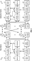
- FIG. 7 shows a block diagram of a detector capable of determining a number of antennas used to transmit a preamble sequence, based on the sequence itself. After determining the number of transmit antennas, the detector may perform MIMO channel estimation.
- the preamble sequences transmitted from the base station may be designed to allow the detector to decode the preamble sequences using Constant Amplitude and Zero Auto Correlation (CAZAC).
- CAZAC sequences possess a feature that autocorrelation between cyclically shifts of same CAZAC sequence is equal to zero, and cross-correlation of cyclic shifts of two different CAZAC sequences is nearly equal to zero.
- the first N CP elements h j,0 from equation (4) represent channel gains for transmit antenna 0, the next N CP elements h j,1 represent channel gains for transmit antenna 1, and so on, and the last N CP elements h j,M-1 represent channel gains for transmit antenna M-1.
- the transmit antenna determination logic 712 may correlate received preamble symbols at any receive antenna j with a plurality of CAZAC sequences that correspond to all supported number of transmit antennas: P H ⁇ y j , where matrix P H is Hermitian version of matrix P from equation (5). Correlation defined by equation (6) may be repeated C times for all C supported number of transmit antennas, where P is unique for the particular configuration of transmit antennas.
- the number of transmit antennas M may be determined without ambiguity at the output of the transmit antenna determination logic 712.
- the CAZAC sequence that corresponds to the particular determined number of transmit antennas M and cyclically shifted with all a priori known (standardized) shift values t 0 through t M-1 that satisfy condition in equation (2) may be applied to the channel estimation logic 714 and correlated with received preamble symbols from all R receive antennas.
- a single-input single-output (SISO) channel between each transmit and each receive antenna in a communication system may be determined without ambiguity at the output of the channel estimation logic 714.
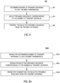
- FIG. 8 illustrates example operations 800 for transmitting a preamble sequence using transmit diversity, with the sequence indicating the number of transmit antennas used, in accordance with certain embodiments of the present disclosure.
- the operations 800 may be performed, for example, by a base station 110 to transmit the preamble sequence from a plurality of transmit antennas via a CDD scheme using a group of modulators, such as those shown in FIG. 6 .
- the operations begin, at 802, by determining a number of transmit antennas to use for a MIMO transmission.
- the base station may be configured to transmit using 2 N antennas (e.g., 1, 2, 4 or 8).
- N antennas e.g. 1, 2, 4 or 8
- a preamble sequence corresponding to the determined number of antennas is selected and, at 806, the selected preamble sequence is transmitted from the number of antennas.
- a receiving mobile station is able to know the number of transmit antennas and may, thus, be able to perform MIMO channel estimation.
- FIG. 9 illustrates example operations 900 that may be performed, for example, at a mobile station receiving the transmitted preamble sequence.
- samples for preamble symbols are received from a number of transmit antennas.
- a correlation is performed on the received symbols with known preamble sequences, to identify the transmitted preamble sequence.
- a received demodulated preamble sequence at the first receive antenna may be correlated with CAZAC sequences that correspond to all C supported number of transmit antennas.
- CAZAC sequences that are not cyclically shifted (or, equivalently, cyclically shifted by zero samples) may be used at the receiver.
- unique information about the number of utilized antennas at the transmitter may be determined.
- channel estimates may be obtained for each transmit-receiver pair. For example, with the number of transmit antennas known, corresponding CAZAC preamble sequence cyclically shifted by all pre-defined cyclic shift values may be correlated with received demodulated preamble sequence at every receive antenna. As a result, estimates of channel gains between every transmit and every receive antenna may be obtained.
- DSP digital signal processor
- ASIC application specific integrated circuit
- FPGA field programmable gate array signal
- PLD programmable logic device
- a general purpose processor may be a microprocessor, but in the alternative, the processor may be any commercially available processor, controller, microcontroller or state machine.
- a processor may also be implemented as a combination of computing devices, e.g., a combination of a DSP and a microprocessor, a plurality of microprocessors, one or more microprocessors in conjunction with a DSP core, or any other such configuration.
- a software module may reside in any form of storage medium that is known in the art. Some examples of storage media that may be used include random access memory (RAM), read only memory (ROM), flash memory, EPROM memory, EEPROM memory, registers, a hard disk, a removable disk, a CD-ROM and so forth.
- RAM random access memory
- ROM read only memory
- flash memory EPROM memory
- EEPROM memory EEPROM memory
- registers a hard disk, a removable disk, a CD-ROM and so forth.
- a software module may comprise a single instruction, or many instructions, and may be distributed over several different code segments, among different programs, and across multiple storage media.
- a storage medium may be coupled to a processor such that the processor can read information from, and write information to, the storage medium. In the alternative, the storage medium may be integral to the processor.
- the methods disclosed herein comprise one or more steps or actions for achieving the described method.
- the method steps and/or actions may be interchanged with one another without departing from the scope of the claims.
- the order and/or use of specific steps and/or actions may be modified without departing from the scope of the claims.
- a storage media may be any available media that can be accessed by a computer.
- such computer-readable media can comprise RAM, ROM, EEPROM, CD-ROM or other optical disk storage, magnetic disk storage or other magnetic storage devices, or any other medium that can be used to carry or store desired program code in the form of instructions or data structures and that can be accessed by a computer.
- Disk and disc include compact disc (CD), laser disc, optical disc, digital versatile disc (DVD), floppy disk, and Blu-ray® disc where disks usually reproduce data magnetically, while discs reproduce data optically with lasers.
- Software or instructions may also be transmitted over a transmission medium.
- a transmission medium For example, if the software is transmitted from a website, server, or other remote source using a coaxial cable, fiber optic cable, twisted pair, digital subscriber line (DSL), or wireless technologies such as infrared, radio, and microwave, then the coaxial cable, fiber optic cable, twisted pair, DSL, or wireless technologies such as infrared, radio, and microwave are included in the definition of transmission medium.
- DSL digital subscriber line
- modules and/or other appropriate means for performing the methods and techniques described herein can be downloaded and/or otherwise obtained by a user terminal and/or base station as applicable.
- a device can be coupled to a server to facilitate the transfer of means for performing the methods and techniques described herein can be downloaded and/or otherwise obtained by a user terminal and/or base station as applicable.
- a device can be coupled to a server to facilitate the transfer of means for performing the methods described herein.
- various methods described herein can be provided via storage means (e.g., RAM, ROM, a physical storage medium such as a compact disc (CD) or floppy disk, etc.), such that a user terminal and/or base station can obtain the various methods upon coupling or providing the storage means to the device.
- storage means e.g., RAM, ROM, a physical storage medium such as a compact disc (CD) or floppy disk, etc.
- CD compact disc
- floppy disk etc.
- any other suitable technique for providing the methods and techniques described herein to a device can be utilized.
- a further embodiment of the present invention includes a method for wireless communications in a multiple input multiple output (MIMO) communications system, comprising:
- Determining, based on the decoded preamble sequence, a number of transmit antennas may comprise: determining the number of transmit antennas used to transmit the preamble sequence.
- Decoding the preamble sequence may comprise: correlating received demodulated preamble sequences with a plurality of known preamble sequences corresponding to different numbers of transmit antennas.
- the preamble sequence may be transmitted with a Constant Amplitude and Zero Auto Correlation (CAZAC) sequence; and correlating received demodulated preamble sequences with a plurality of known preamble sequences may comprise correlating the received demodulated preamble sequences with a plurality of known CAZAC sequences corresponding to different numbers of transmit antennas.
- CAZAC Constant Amplitude and Zero Auto Correlation
- the preamble sequence may be transmitted from a plurality of transmit antennas using a Cyclic Delay Diversity (CDD) transmission scheme.
- CDD Cyclic Delay Diversity
- the above method may further comprise performing channel estimation for a plurality of pairs of the receive and transmit antennas.
- a further embodiment of the present invention includes a method for wireless communications in a multiple input multiple output (MIMO) communications system, comprising:
- the selected preamble sequence may be a Constant Amplitude and Zero Auto Correlation (CAZAC) sequence, selected from a plurality of CAZAC sequences corresponding to different numbers of transmit antennas.
- CAZAC Constant Amplitude and Zero Auto Correlation
- Transmitting the selected preamble sequence from the determined number of transmit antennas may comprise transmitting the preamble sequence from a plurality of transmit antennas using a Cyclic Delay Diversity (CDD) transmission scheme.
- CDD Cyclic Delay Diversity
- a further embodiment of the present invention includes a device for wireless communications in a multiple input multiple output (MIMO) communications system, comprising:
- the logic for determining the number of transmit antennas may be configured to determine the number of transmit antennas used to transmit the preamble sequence.
- the logic for decoding the preamble sequence may be configured to: correlate received demodulated preamble sequences with a plurality of known preamble sequences corresponding to different numbers of transmit antennas.
- the preamble sequence may be transmitted with a Constant Amplitude and Zero Auto Correlation (CAZAC) sequence; and the logic for decoding the preamble sequence may be configured to correlate received demodulated preamble sequences with a plurality of known preamble sequences comprises correlating the received demodulated preamble sequences with a plurality of known CAZAC sequences corresponding to different numbers of transmit antennas.
- CAZAC Constant Amplitude and Zero Auto Correlation
- the preamble sequence may be transmitted from a plurality of transmit antennas using a Cyclic Delay Diversity (CDD) transmission scheme.
- CDD Cyclic Delay Diversity
- the device may further comprise logic for performing channel estimation for a plurality of pairs of the receive and transmit antennas.
- a further embodiment of the present invention includes a device for wireless communications in a multiple input multiple output (MIMO) communications system, comprising:
- the selected preamble sequence may be a Constant Amplitude and Zero Auto Correlation (CAZAC) sequence, selected from a plurality of CAZAC sequences corresponding to different numbers of transmit antennas.
- CAZAC Constant Amplitude and Zero Auto Correlation
- the logic for transmitting the selected preamble sequence from the determined number of transmit antennas may be configured to transmit the preamble sequence from a plurality of transmit antennas using a Cyclic Delay Diversity (CDD) transmission scheme.
- CDD Cyclic Delay Diversity
- a further embodiment of the present invention includes an apparatus for wireless communications in a multiple input multiple output (MIMO) communications system, comprising:
- the means for determining the number of transmit antennas may be configured to determine the number of transmit antennas used to transmit the preamble sequence.
- the means for decoding the preamble sequence may be configured to: correlate received demodulated preamble sequences with a plurality of known preamble sequences corresponding to different numbers of transmit antennas.
- the preamble sequence may be transmitted with a Constant Amplitude and Zero Auto Correlation (CAZAC) sequence; and the means for decoding the preamble sequence may be configured to correlate received demodulated preamble sequences with a plurality of known preamble sequences comprises correlating the received demodulated preamble sequences with a plurality of known CAZAC sequences corresponding to different numbers of transmit antennas.
- CAZAC Constant Amplitude and Zero Auto Correlation
- the preamble sequence may be transmitted from a plurality of transmit antennas using a Cyclic Delay Diversity (CDD) transmission scheme.
- CDD Cyclic Delay Diversity
- the apparatus may further comprise means for performing channel estimation for a plurality of pairs of the receive and transmit antennas.
- a further embodiment of the present invention includes an apparatus for wireless communications in a multiple input multiple output (MIMO) communications system, comprising:
- the selected preamble sequence may be a Constant Amplitude and Zero Auto Correlation (CAZAC) sequence, selected from a plurality of CAZAC sequences corresponding to different numbers of transmit antennas.
- CAZAC Constant Amplitude and Zero Auto Correlation
- the means for transmitting the selected preamble sequence from the determined number of transmit antennas may be configured to transmit the preamble sequence from a plurality of transmit antennas using a Cyclic Delay Diversity (CDD) transmission scheme.
- CDD Cyclic Delay Diversity
- a further embodiment of the present invention includes a computer-program product for wireless communications in a multiple input multiple output (MIMO) communications system, comprising:
- the instructions for determining, based on the decoded preamble sequence, a number of transmit antennas may comprise: instructions for determining the number of transmit antennas used to transmit the preamble sequence.
- the instructions for decoding the preamble sequence may comprise: instructions for correlating received demodulated preamble sequences with a plurality of known preamble sequences corresponding to different numbers of transmit antennas.
- the preamble sequence may be transmitted with a Constant Amplitude and Zero Auto Correlation (CAZAC) sequence; and the instructions for correlating received demodulated preamble sequences with a plurality of known preamble sequences comprise instructions for correlating the received demodulated preamble sequences with a plurality of known CAZAC sequences corresponding to different numbers of transmit antennas.
- CAZAC Constant Amplitude and Zero Auto Correlation
- the preamble sequence may be transmitted from a plurality of transmit antennas using a Cyclic Delay Diversity (CDD) transmission scheme.
- CDD Cyclic Delay Diversity
- the computer-program product may further comprise instructions for performing channel estimation for a plurality of pairs of the receive and transmit antennas.
- a further embodiment of the present invention includes a computer-program product for wireless communications in a multiple input multiple output (MIMO) communications system, comprising:
- the selected preamble sequence may be a Constant Amplitude and Zero Auto Correlation (CAZAC) sequence, selected from a plurality of CAZAC sequences corresponding to different numbers of transmit antennas.
- CAZAC Constant Amplitude and Zero Auto Correlation
- the instructions for transmitting the selected preamble sequence from the determined number of transmit antennas may comprise instructions for transmitting the preamble sequence from a plurality of transmit antennas using a Cyclic Delay Diversity (CDD) transmission scheme.
- CDD Cyclic Delay Diversity
Description
- The present disclosure generally relates to MIMO communication systems and, more specifically, to a method for determining the number of transmit antennas used at the base station during the initial synchronization with mobile subscriber.
- Multiple-input multiple-output (MIMO) wireless communications systems utilize multiple transmit and receive antennas to achieve transmit and receiver diversity, which may allow for more reliable communications and/or improved data throughput. While multiple transmit antennas are available, the preamble or the primary synchronization signal in a MIMO system is typically transmitted to the mobile subscriber by utilizing only one effective transmit antenna at the base station. This is due to the fact that during the initial access the subscriber does not know the number of antennas at the base station. As a result, the transmission diversity as an inherent feature for a plurality of antennas is not utilized during the initial access.
- In the developing of IEEE 802.16m standard, a broadcast channel (BCH) needs to be decoded by the mobile subscriber following its primary synchronization with the base station. The BCH may contain system-wide parameters in order to enable the initial access. In addition, the BCH may be transmitted by utilizing a plurality of transmit antennas. Instead of providing pilots for the BCH message, cyclic delay diversity (CDD) scheme may be utilized to transmit delayed copies of a preamble from multiple antennas. To accomplish this, information about the number of transmit antennas utilized by the base station and channel estimates need to be obtained before decoding the BCH message.
- Therefore, there is a need in the art for conveying the number of transmit antennas that are utilized at the base station, ideally during primary synchronization with the mobile subscriber.
-
US2006/056528 A1 discloses a method of transmitting and receiving preamble sequences in a transmitter in an OFDM communication system. A transmitter segments a first sequence of a predetermined length into a predetermined number of second sequences, generates as many preamble sequences as the second sequences by applying different time offsets to the second sequences, selects a predetermined number of preamble sequences among the generated preamble sequences, maps the selected preamble sequences to the transmit antennas, and transmits the mapped preamble sequences through the transmit antennas. -
EP1892865 A1 discloses that a transmitter includes an amplitude adjustment unit multiplying an amplitude adjustment sequence value for adjusting amplitude with a synchronization channel transmitted from a base station for establishing synchronization with a mobile station. - The present disclosure provides a method, apparatus and computer-program product implementing the method for wireless communications in a multiple input multiple output (MIMO) communications system. The method includes decoding a preamble sequence based on symbols received from a plurality of receive antennas and determining, based on the decoded preamble sequence, a number of transmit antennas used to transmit the preamble sequence.
- The present disclosure further provides a method, apparatus and computer-program product implementing the method for wireless communications in a multiple input multiple output (MIMO) communications system. The method includes determining a number of transmit antennas to use for a transmission, selecting, from a plurality of preamble sequences corresponding to different numbers of transmit antennas, a preamble sequence corresponding to the determined number of transmit antennas, and transmitting the selected preamble sequence from the determined number of transmit antennas.
- So that the manner in which the above recited features of the present disclosure can be understood in detail, a more particular description, briefly summarized above, may be had by reference to embodiments, some of which are illustrated in the appended drawings. It is to be noted, however, that the appended drawings illustrate only certain typical embodiments of this disclosure and are therefore not to be considered limiting of its scope, for the description may admit to other equally effective embodiments.
-
FIG. 1 illustrates a wireless communication system with multiple base stations and multiple subscriber stations in accordance with certain embodiments of the present disclosure. -
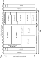
FIG. 2 illustrates an example frame structure for a time division duplex (TDD) mode in IEEE 802.16 in accordance with certain embodiments of the present disclosure. -
FIG. 3 illustrates an example block diagram of a design of a base station and a subscriber station, in accordance with certain embodiments of the present disclosure. -
FIG. 4 illustrates a block diagram of a design of an OFDM modulator in accordance with certain embodiments of the present disclosure. -
FIG. 5 illustrates an example cyclic delay diversity (CDD) transmission scheme for a wireless system with M = 4 transmit antennas in accordance with certain embodiments of the present disclosure. -
FIG. 6 illustrates an example block diagram if a design of modulators at the base station ofFIG. 3 in accordance with certain embodiments of the present disclosure. -
FIG. 7 illustrates an example block diagram of a detector at a subscriber station for determining the number of antennas used at the base station and for estimating MIMO channels during primary synchronization in accordance with certain embodiments of the present disclosure. -
FIG. 8 illustrates example operations for transmitting a preamble sequence using transmit diversity, with the sequence indicating the number of transmit antennas used, in accordance with certain embodiments of the present disclosure. -
FIG. 8A illustrates example components capable of performing the operations illustrated inFIG. 8 . -
FIG. 9 illustrates example operations for determining the number of transmit antennas used at the base station and for estimating MIMO channels during primary synchronization, in accordance with certain embodiments of the present disclosure. -
FIG. 9A illustrates example components capable of performing the operations illustrated inFIG. 9 . - For certain embodiments of the present disclosure, a base station may apply transmit diversity during primary synchronization by transmitting a preamble sequence from a plurality of transmit antennas. The preamble sequence may be selected to convey the number of transmit antennas used during the transmission. As a result, after properly decoding the preamble sequence, a receiving mobile station (or subscriber station) may know the number of antennas used at the base station allowing for channel estimation. Thus, certain embodiments that may allow the benefits of transmit diversity may be achieved when transmitting the primary synchronization signal, such as a 802.16m broadcast channel (BCH) that may contain system-wide parameters used for system access.
- By reserving a set of preamble sequences, each associated with a different number of transmit antennas used at the base station, a mobile station may simultaneously obtain synchronization and determine the number of transmit antennas. With knowledge of the number of transmit antennas, the mobile station may perform MIMO channel estimation, for example, based on knowledge of the transmission scheme (e.g., CDD) used to transmit the preamble sequence.
- The word "exemplary" is used herein to mean "serving as an example, instance, or illustration." Any embodiment described herein as "exemplary" is not necessarily to be construed as preferred or advantageous over other embodiments.
- The techniques described herein may be used for various communication systems such as Code Division Multiple Access (CDMA) systems, Time Division Multiple Access (TDMA) systems, Frequency Division Multiple Access (FDMA) systems, Orthogonal FDMA (OFDMA) systems, Single-Carrier FDMA (SC-FDMA) systems, Spatial Division Multiple Access (SDMA) systems, wireless local area networks (WLANs), etc. The terms "system" and "network" are often used interchangeably. An OFDMA system may implement an air interface such as Ultra Mobile Broadband (UMB), Evolved UTRA (E-UTRA), IEEE 802.11 (which is also referred to as Wi-Fi), IEEE 802.16 (which is also referred to as WiMAX), IEEE 802.20, Flash-OFDM®, etc. These various air interfaces and standards are known in the art.
- For clarity, certain aspects of the techniques are described below for WiMAX, and WiMAX terminology is used in much of the description below. WiMAX is described in IEEE 802.16, entitled "Part 16: Air Interface for Fixed and Mobile Broadband Wireless Access Systems," dates October 1, 2004, and in IEEE 802.16e, entitled "Part 16: Air Interface for Fixed and Mobile Broadband Wireless Access Systems; Amendment 2: Physical and Medium Access Control Layers for Combined Fixed and Mobile Operation in Licensed Bands," dates February 28, 2006. These documents are publicly available. The techniques may also be used for IEEE 802.16m, which is a new air interface being developed for WiMAX.
-
FIG. 1 shows awireless communication system 100 with multiple base stations (BS) 110 and multiple subscriber station (SS) 120. A base station is a station that supports communication for subscriber stations and may perform functions such as connectivity, management, and control of subscriber stations. A base station may also be referred to as a Node B, an evolved Node B, an access point, etc. Asystem controller 130 may couple tobase stations 110 and provide coordination and control for these base stations. -
Subscriber stations 120 may be dispersed throughout the system, and each subscriber station may be stationary or mobile. A subscriber station may also be referred to as a mobile station, a terminal, an access terminal, user equipment, a subscriber unit, subscriber station, etc. A subscriber station may be a cellular phone, a personal digital assistant (PDA), a wireless device, a wireless modem, a handheld device, a laptop computer, a cordless phone, etc. A subscriber station may communicate with a base station on the downlink (DL) and/or uplink (UL). The downlink (or forward link) refers to the communication link from the base station to the subscriber station, and the uplink (or reverse link) refers to the communication link from the subscriber station to the base station. -
FIG. 2 shows anexample frame structure 200 for a time division duplex (TDD) mode in IEEE 802.16. The transmission timeline may be partitioned into units of frames. Each frame may span predetermined time duration, e.g., 5 milliseconds (ms), and may be partitioned into a downlink subframe and an uplink subframe. In general, the downlink and uplink subframes may cover any fraction of a frame. The downlink and uplink subframes may be separated by a transmit transmission gap (TTG) and a receive transmission gap (RTG). - A number of physical subchannels may be defined. Each physical subchannel may include a set of subcarriers that may be contiguous or distributed across the system bandwidth. A number of logical subchannels may also be defined and may be mapped to the physical subchannels based on a known mapping. The logical subchannels may simplify the allocation of resources.
- As shown in
FIG. 2 , a downlink subframe may include a preamble, a frame control header (FCH), a downlink map (DL-MAP), an uplink map (UL-MAP), and downlink (DL) bursts. The preamble may carry a known transmission that may be used by subscriber stations for frame detection and synchronization. The FCH may carry parameters used to receive the DL-MAP, the UL-MAP, and the downlink bursts. The DL-MAP may carry a DL-MAP message, which may include information elements (IEs) for various types of control information (e.g., resource allocation or assignment) for downlink access. The UL-MAP may carry a UL-MAP message, which may include IEs for various types of control information for uplink access. The downlink bursts may carry data for the subscriber stations being served. An uplink subframe may include uplink bursts, which may carry data transmitted by the subscriber stations scheduled for uplink transmission. - The preamble transmission techniques described herein may be used for multiple-input multiple-output (MIMO) transmission as well as multiple-input single-output transmission (MISO) transmission. The techniques may also be used for preamble transmission on the downlink as well as the uplink. For clarity, certain aspects of the techniques are described below for preamble transmission on the downlink with MIMO.
-
FIG. 3 shows a block diagram of a design of abase station 110 and asubscriber station 120, which are one of the base stations and one of the subscriber stations inFIG. 1 .Base station 110 is equipped with multiple (M)antennas 334a through 334m.Subscriber station 120 is equipped with multiple (R)antennas 352a through 352r. - At
base station 110, transmit (TX)data processor 320 may receive data from adata source 312, process (e.g., encode and symbol map) the data based on one or more modulation and coding schemes, and provide data symbols. As used herein, a data symbol is a symbol for data, a preamble symbol is a symbol for preamble, and a symbol may be a real or complex value. The data and preamble symbols may be modulation symbols from a modulation scheme such as PSK or QAM. The preamble (or pilot signal, in general) may comprise data that are known a priori by both the base station and the subscriber station. ATX MIMO processor 330 may process the data and pilot symbols and provide M output symbol streams to M modulators (MOD) 332a through 332m. Each modulator 332 may process its output symbol stream (e.g., for OFDM) to obtain an output sample stream. Each modulator 332 may further condition (e.g., convert to analog, filter, amplify, and upconvert) its output sample stream and generate a downlink signal. The M downlink signals frommodulators 332a through 332m may be transmitted viaantennas 334a through 334m, respectively. - At
subscriber station 120,R antennas 352a through 352r may receive the M downlink signals frombase station 110, and each antenna 352 may provide a received signal to an associated demodulator (DEMOD) 354. Each demodulator 354 may condition (e.g., filter, amplify, downconvert, and digitize) its received signal to obtain input samples and may further process the input samples (e.g., for OFDM) to obtain received symbols. Each demodulator 354 may provide received data symbols to aMIMO detector 360 and provide the received pilot symbols to achannel processor 394.Channel processor 394 may estimate the response of a MIMO channel frombase station 110 tosubscriber station 120 based on the received pilot symbols and provide a MIMO channel estimate toMIMO detector 360.MIMO detector 360 may perform MIMO detection on the received symbols based on the MIMO channel estimate and provide detected symbols, which are estimates of the transmitted data symbols. A receive (RX)data processor 370 may process (e.g., symbol demap and decode) the detected symbols and provide decoded data to adata sink 372. -
Subscriber station 120 may evaluate the channel conditions and generate feedback information, which may comprise various types of information. The feedback information and data from adata source 378 may be processed (e.g., encoded and symbol mapped) by aTX data processor 380, spatially processed by aTX MIMO processor 382, and further processed bymodulators 354a through 354r to generate R uplink signals, which may be transmitted viaantennas 352a through 352r. Atbase station 110, the R uplink signals fromsubscriber station 120 may be received byantennas 334a through 334m, processed bydemodulators 332a through 332m, spatially processed by aMIMO detector 336, and further processed (e.g., symbol demapped and decoded) by anRX data processor 338 to recover the feedback information and data sent bysubscriber station 120. Controller/processor 340 may control data transmission tosubscriber station 120 based on the feedback information. - Controllers/
processors base station 110 andsubscriber station 120, respectively.Memories base station 110 andsubscriber station 120, respectively. Ascheduler 344 may schedulesubscriber station 120 and/or other subscriber stations for data transmission on the downlink and/or uplink based on the feedback information received from all subscriber stations. - IEEE 802.16 utilizes orthogonal frequency division multiplexing (OFDM) for the downlink and uplink. OFDM partitions the system bandwidth into multiple (NFFT) orthogonal subcarriers, which may also be referred to as tones, bins, etc. Each subcarrier may be modulated with data or pilot. The number of subcarriers may be dependent on the system bandwidth as well as the frequency spacing between adjacent subcarriers. For example, NFFT may be equal to 128, 256, 512, 1024 or 2048. Only a subset of the NFFT total subcarriers may be usable for transmission of data and pilot, and the remaining subcarriers may serve as guard subcarriers to allow the system to meet spectral mask requirements. In the following description, a data subcarrier is a subcarrier used for data, and a pilot subcarrier is a subcarrier used for pilot. An OFDM symbol may be transmitted in each OFDM symbol period (or simply, a symbol period). Each OFDM symbol may include data subcarriers used to send data, pilot subcarriers used to send pilot, and/or guard subcarriers not used for data or pilot.
-
FIG. 4 shows a block diagram of a design of anOFDM modulator 400, which may be included in each of modulators 332a through 332m andmodulators 354a through 354r inFIG. 3 . WithinOFDM modulator 400, a symbol-to-subcarrier mapper 410 receives and maps output symbols to the NFFT total subcarriers. In each OFDM symbol period, aunit 412 transforms NFFT output symbols for the NFFT total subcarriers to the time domain with an NFFT-point inverse discrete Fourier transform (IDFT) and provides a useful portion containing NFFT time-domain samples. Each sample is a complex value to be transmitted in one chip period. A parallel-to-serial (P/S)converter 414 serializes the NFFT samples in the useful portion. Acyclic prefix generator 416 copies the last NCP samples of the useful portion and appends these NCP samples to the front of the useful portion to form an OFDM symbol containing NFFT + NCP samples. Each OFDM symbol thus contains a useful portion of NFFT samples and a cyclic prefix of NCP samples. The cyclic prefix is used to combat intersymbol interference (ISI) and inter-carrier interference (ICI) caused by delay spread in a wireless channel. - Referring back to
FIG. 3 , on the downlink, a MIMO channel is formed by the M transmit antennas atbase station 110 and the R receive antennas atsubscriber station 120. This MIMO channel is composed of M·R single-input single-output (SISO) channels or one SISO channel for each possible pair of transmit and receive antennas. The channel response for each SISO channel may be characterized by either a time-domain channel impulse response or a corresponding frequency-domain channel frequency response. The channel frequency response is the discrete Fourier transform (DFT) of the channel impulse response. - The channel impulse response for each SISO channel may be characterized by L time-domain channel taps, where L is typically much less than NFFT. That is, if an impulse is applied at a transmit antenna, then L time-domain samples at the sample rate taken at a receive antenna for this impulse stimulus would be sufficient to characterize the response of the SISO channel. The required number of channel taps (L) for the channel impulse response is dependent on the delay spread of the system, which is the time difference between the earliest and latest arriving signal instances of sufficient energy at the receive antenna.
- Each SISO channel may include one or more propagation paths between the transmit antenna and the receive antenna for that SISO channel, with the propagation paths being determined by the wireless environment. Each path may be associated with a particular complex gain and a particular delay. For each SISO channel, the complex gains of the L channel taps are determined by the complex gains of the paths for that SISO channel. Each SISO channel thus has a channel profile with paths d 0 through d L-1, where the complex gain of each path dl may be a zero or non-zero value.
- As described herein, for certain embodiments, a base station may apply transmit diversity during primary synchronization by transmitting a preamble sequence from a plurality of transmit antennas. The particular preamble sequence may be selected to indicate the number of transmit antennas used to transmit the sequence. As a result, a mobile station may simultaneously obtain synchronization and determine the number of transmit antennas. With knowledge of the number of transmit antennas, the mobile station may perform MIMO channel estimation based on knowledge of the transmission scheme used to transmit the preamble sequence.
- For certain embodiments, a cyclic delay diversity (CDD) scheme may be used to transmit the preamble sequence from the base station. Cyclic delay diversity (CDD) may be used to create frequency diversity in a MIMO transmission, which may improve error rate performance. With cyclic delay diversity, the OFDM symbols for each transmit antenna may be cyclically delayed by a different amount, as described below. M different cyclically delayed signals may be transmitted from the M transmit antennas. However, cyclic delay diversity may adversely impact MIMO channel estimation in some instances. In particular, it may not be possible to separate paths if a cyclically delayed signal matches a path delay in the channel profile. For example, for a given receive antenna, it may not be possible to determine whether a complex gain for a delay of two samples is from (i) a downlink signal from the first transmit antenna with no cyclic delay and received via a path with a delay of two samples, or (ii) a downlink signal from the second transmit antenna with a cyclic delay of one sample and received via a path with a delay of one sample, or (iii) a downlink signal from the third transmit antenna with a cyclic delay of two samples and received via a path with no delay.
- If the channel profile has paths d 0 through d L-1 and if the M downlink signals from the M transmit antennas have cyclic delays of t 0 through t M-1, then the L channel taps for each SISO channel may be determined without ambiguity if (dl + tm ) mod TS is distinct for all values of indices l and m, where l = 0,..., L -1, m = 0,..., M -1, TS is the duration of the useful portion and may be equal to NFFT samples, and "mod" denotes a modulo operation. This condition is applicable for full frequency reuse.
- In one embodiment of the present disclosure, the cyclic delay tm for each transmit antenna (except for one transmit antenna with cyclic delay of zero) may be selected to be greater than the maximum expected delay spread in the system. The cyclic prefix length NCP may be selected such that it is greater than the maximum expected delay spread in the system, so that L ≤ NCP. Thus, the cyclic delay for each transmit antenna may be selected to be an integer multiple of the cyclic prefix length, as follows:

-
FIG. 5 shows cyclic delay diversity with applied cyclic shifts from equation (1) for an illustrative example of M = 4 transmit antennas. Transmitantenna 0 may have a cyclic shift of zero, and useful portion may be cyclically shifted/delayed by zero samples for this transmit antenna. Transmitantenna 1 may have a cyclic shift of NCP, and the useful portion may be cyclically shifted by NCP samples for this transmit antenna. Transmitantenna 2 may have a cyclic shift of 2NCP, and the useful portion may be cyclically shifted by 2NCP samples for this transmit antenna. Transmitantenna 3 may have a cyclic shift of 3NCP, and the useful portion may be cyclically shifted by 3NCP samples for this transmit antenna. - In general, the cyclic shits (delays) for the M transmit antennas may be selected as follows:

-
FIG. 6 shows a block diagram of a design ofmodulators 332a through 332m atbase station 110 inFIG. 3 . For simplicity,FIG. 6 shows only the processing to generate preamble for M transmit antennas.Base station 110 may transmit preamble symbols from M transmit antennas in a manner to facilitate channel estimation by thesubscriber station 120. The preamble symbols may be sent on S subcarriers, where in general S ≤ NFFT. Withinmodulator 332a for transmitantenna 0, a symbol-to-subcarrier mapper 610a maps preamble symbols to preamble subcarriers and maps zero symbols to remaining subcarriers. AnIDFT unit 612a performs an NFFT-point IDFT on the NFFT preamble and zero symbols and provides NFFT time-domain samples. A P/S converter 614a serializes the NFFT samples. Acyclic delay unit 616a cyclically shifts the NFFT samples by 0 samples for transmitantenna 0. Acyclic prefix generator 618a appends a cyclic prefix and provides an OFDM symbol comprising a first preamble for transmitantenna 0. -
Modulator 332b may similarly generate an OFDM symbol comprising a second preamble for transmitantenna 1. However, acyclic delay unit 616b cyclically shifts the NFFT samples by NCP samples for transmitantenna 1. Each remaining modulator 332 may similarly generate an OFDM symbol comprising a preamble for corresponding transmit antenna but may cyclically shift the NFFT samples by m·NCP samples for transmit antenna m. - In order to determine antenna configuration at the base station, different preamble sequence for every supported number of transmit antennas may be utilized as the primary synchronization signal. As an illustrative example, if one, two and four antennas are supported at the base station, then it may be required to reserve three different preamble sequences as primary synchronization signals. In order to accurately detect the number of transmit antennas, the preamble sequences may be generated such that autocorrelation between cyclic shifts of same sequence is equal to zero and cross-correlation between cyclic shifts of distinct sequences is nearly equal to zero.
- In the Long Term Evolution (LTE) and Worldwide Interoperability for Microwave Access (WiMAX) standards, a set of Constant Amplitude and Zero Auto Correlation (hereinafter abbreviated as CAZAC) sequences may be used as pilot sequences for channel estimation following the primary synchronization between mobile subscriber and base station. In this disclosure, the CAZAC sequences are utilized to determine the number of transmit antennas during the primary synchronization. After that, by correlating received samples with delayed version of transmitted CAZAC sequences and by knowing the number of transmit antennas, it may be possible to recover the channel impulse response between every transmit and every receive antenna.
- As described herein, for certain embodiments, a base station may apply transmit diversity during primary synchronization by transmitting a preamble sequence from a plurality of transmit antennas. The particular preamble sequence may be selected to indicate the number of transmit antennas used to transmit the sequence. As a result, a mobile station may simultaneously obtain synchronization and determine the number of transmit antennas. With knowledge of the number of transmit antennas, the mobile station may perform MIMO channel estimation based on knowledge of the transmission scheme used to transmit the preamble sequence
-
FIG. 7 shows a block diagram of a detector capable of determining a number of antennas used to transmit a preamble sequence, based on the sequence itself. After determining the number of transmit antennas, the detector may perform MIMO channel estimation. For certain embodiments, the preamble sequences transmitted from the base station may be designed to allow the detector to decode the preamble sequences using Constant Amplitude and Zero Auto Correlation (CAZAC). CAZAC sequences possess a feature that autocorrelation between cyclically shifts of same CAZAC sequence is equal to zero, and cross-correlation of cyclic shifts of two different CAZAC sequences is nearly equal to zero. - The NFFT received preamble symbols for each receive antenna j in
FIG. 7 may be expressed as:

antenna 0, the next NCP elements hj,1 represent channel gains for transmitantenna 1, and so on, and the last NCP elements hj,M-1 represent channel gains for transmit antenna M-1. An (NFFT×M·NCP) matrix P of CAZAC preamble sequences from equation (3) for a plurality of M transmit antennas may be defined as follows:
block 710 inFIG. 7 for an exemplary case of C=3. Since the number of transmit antennas M is not known a-priori, the value of M may be fixed to a maximum number Mmax of antennas supported in the system. - The transmit
antenna determination logic 712 may correlate received preamble symbols at any receive antenna j with a plurality of CAZAC sequences that correspond to all supported number of transmit antennas:
- Making use of the fact that the autocorrelation between cyclic shifts of a given CAZAC sequence is exactly zero and that the cross-correlation between cyclic shifts of two different CAZAC sequences are nearly zero, one can figure out which preamble sequence was actually transmitted using the CDD scheme described above. If the preamble hypothesis in the correlation given by equation (6) matches the actual preamble sent, then the correlation provides the vector of channel taps between all transmit and the jth receive antenna. If the preamble hypothesis does not match the actual preamble sent, the correlation given by equation (6) will provide a vector with each position containing a linear combination of all channel taps between all transmit and jth receive antenna. These two cases can be distinguished by comparing the peaky behavior of the correlation output.
- Therefore, the number of transmit antennas M may be determined without ambiguity at the output of the transmit
antenna determination logic 712. The CAZAC sequence that corresponds to the particular determined number of transmit antennas M and cyclically shifted with all a priori known (standardized) shift values t 0 through t M-1 that satisfy condition in equation (2) may be applied to thechannel estimation logic 714 and correlated with received preamble symbols from all R receive antennas.. - Because the autocorrelation of CAZAC sequences with different cyclic shifts provide zero result and the CDD scheme may be utilized for the transmission, a single-input single-output (SISO) channel between each transmit and each receive antenna in a communication system may be determined without ambiguity at the output of the
channel estimation logic 714. -
FIG. 8 illustratesexample operations 800 for transmitting a preamble sequence using transmit diversity, with the sequence indicating the number of transmit antennas used, in accordance with certain embodiments of the present disclosure. Theoperations 800 may be performed, for example, by abase station 110 to transmit the preamble sequence from a plurality of transmit antennas via a CDD scheme using a group of modulators, such as those shown inFIG. 6 . - The operations begin, at 802, by determining a number of transmit antennas to use for a MIMO transmission. For example, the base station may be configured to transmit using 2N antennas (e.g., 1, 2, 4 or 8). At 804, a preamble sequence corresponding to the determined number of antennas is selected and, at 806, the selected preamble sequence is transmitted from the number of antennas. Upon successful decoding of the preamble sequence, a receiving mobile station is able to know the number of transmit antennas and may, thus, be able to perform MIMO channel estimation.
-
FIG. 9 illustratesexample operations 900 that may be performed, for example, at a mobile station receiving the transmitted preamble sequence. At 902, samples for preamble symbols are received from a number of transmit antennas. At 904, a correlation is performed on the received symbols with known preamble sequences, to identify the transmitted preamble sequence. - As described above, the mth preamble sequence may be generated based on the mth cyclic delay and sent from the mth transmit antenna, where m = 1, 2, ..., M. Thus, a received demodulated preamble sequence at the first receive antenna may be correlated with CAZAC sequences that correspond to all C supported number of transmit antennas. For example, CAZAC sequences that are not cyclically shifted (or, equivalently, cyclically shifted by zero samples) may be used at the receiver. As a result of correlation, unique information about the number of utilized antennas at the transmitter may be determined.
- At 904, using the number of antennas, channel estimates may be obtained for each transmit-receiver pair. For example, with the number of transmit antennas known, corresponding CAZAC preamble sequence cyclically shifted by all pre-defined cyclic shift values may be correlated with received demodulated preamble sequence at every receive antenna. As a result, estimates of channel gains between every transmit and every receive antenna may be obtained.
- The various operations of methods described above may be performed by various hardware and/or software component(s) and/or module(s) corresponding to means-plus-function blocks illustrated in the Figures. Generally, where there are methods illustrated in Figures having corresponding counterpart means-plus-function Figures, the operation blocks correspond to means-plus-function blocks with similar numbering. For example, blocks 802-806 illustrated in
FIG. 8 correspond to means-plus-function blocks 802A-806A illustrated inFIG. 8A . Similarly, blocks 902-906 illustrated inFIG. 9 correspond to means-plus-function blocks 902A-906A illustrated inFIG. 9A . - The various illustrative logical blocks, modules and circuits described in connection with the present disclosure may be implemented or performed with a general purpose processor, a digital signal processor (DSP), an application specific integrated circuit (ASIC), a field programmable gate array signal (FPGA) or other programmable logic device (PLD), discrete gate or transistor logic, discrete hardware components or any combination thereof designed to perform the functions described herein. A general purpose processor may be a microprocessor, but in the alternative, the processor may be any commercially available processor, controller, microcontroller or state machine. A processor may also be implemented as a combination of computing devices, e.g., a combination of a DSP and a microprocessor, a plurality of microprocessors, one or more microprocessors in conjunction with a DSP core, or any other such configuration.
- The steps of a method or algorithm described in connection with the present disclosure may be embodied directly in hardware, in a software module executed by a processor, or in a combination of the two. A software module may reside in any form of storage medium that is known in the art. Some examples of storage media that may be used include random access memory (RAM), read only memory (ROM), flash memory, EPROM memory, EEPROM memory, registers, a hard disk, a removable disk, a CD-ROM and so forth. A software module may comprise a single instruction, or many instructions, and may be distributed over several different code segments, among different programs, and across multiple storage media. A storage medium may be coupled to a processor such that the processor can read information from, and write information to, the storage medium. In the alternative, the storage medium may be integral to the processor.
- The methods disclosed herein comprise one or more steps or actions for achieving the described method. The method steps and/or actions may be interchanged with one another without departing from the scope of the claims. In other words, unless a specific order of steps or actions is specified, the order and/or use of specific steps and/or actions may be modified without departing from the scope of the claims.
- The functions described may be implemented in hardware, software, firmware or any combination thereof. If implemented in software, the functions may be stored as one or more instructions on a computer-readable medium. A storage media may be any available media that can be accessed by a computer. By way of example, and not limitation, such computer-readable media can comprise RAM, ROM, EEPROM, CD-ROM or other optical disk storage, magnetic disk storage or other magnetic storage devices, or any other medium that can be used to carry or store desired program code in the form of instructions or data structures and that can be accessed by a computer. Disk and disc, as used herein, include compact disc (CD), laser disc, optical disc, digital versatile disc (DVD), floppy disk, and Blu-ray® disc where disks usually reproduce data magnetically, while discs reproduce data optically with lasers.
- Software or instructions may also be transmitted over a transmission medium. For example, if the software is transmitted from a website, server, or other remote source using a coaxial cable, fiber optic cable, twisted pair, digital subscriber line (DSL), or wireless technologies such as infrared, radio, and microwave, then the coaxial cable, fiber optic cable, twisted pair, DSL, or wireless technologies such as infrared, radio, and microwave are included in the definition of transmission medium.
- Further, it should be appreciated that modules and/or other appropriate means for performing the methods and techniques described herein can be downloaded and/or otherwise obtained by a user terminal and/or base station as applicable. For example, such a device can be coupled to a server to facilitate the transfer of means for performing the methods and techniques described herein can be downloaded and/or otherwise obtained by a user terminal and/or base station as applicable. For example, such a device can be coupled to a server to facilitate the transfer of means for performing the methods described herein. Alternatively, various methods described herein can be provided via storage means (e.g., RAM, ROM, a physical storage medium such as a compact disc (CD) or floppy disk, etc.), such that a user terminal and/or base station can obtain the various methods upon coupling or providing the storage means to the device. Moreover, any other suitable technique for providing the methods and techniques described herein to a device can be utilized.
- It is to be understood that the claims are not limited to the precise configuration and components illustrated above. Various modifications, changes and variations may be made in the arrangement, operation and details of the methods and apparatus described above without departing from the scope of the claims.
- A further embodiment of the present invention includes a method for wireless communications in a multiple input multiple output (MIMO) communications system, comprising:
- decoding a preamble sequence based on symbols received from one or more receive antennas; and
- determining, based on the decoded preamble sequence, a number of transmit antennas.
- Determining, based on the decoded preamble sequence, a number of transmit antennas may comprise:
determining the number of transmit antennas used to transmit the preamble sequence. - Decoding the preamble sequence may comprise:
correlating received demodulated preamble sequences with a plurality of known preamble sequences corresponding to different numbers of transmit antennas.
The preamble sequence may be transmitted with a Constant Amplitude and Zero Auto Correlation (CAZAC) sequence; and correlating received demodulated preamble sequences with a plurality of known preamble sequences may comprise correlating the received demodulated preamble sequences with a plurality of known CAZAC sequences corresponding to different numbers of transmit antennas. - The preamble sequence may be transmitted from a plurality of transmit antennas using a Cyclic Delay Diversity (CDD) transmission scheme.
- The above method may further comprise performing channel estimation for a plurality of pairs of the receive and transmit antennas.
- A further embodiment of the present invention includes a method for wireless communications in a multiple input multiple output (MIMO) communications system, comprising:
- determining a number of transmit antennas to use for a transmission;
- selecting, from a plurality of preamble sequences corresponding to different numbers of transmit antennas, a preamble sequence corresponding to the determined number of transmit antennas; and
- transmitting the selected preamble sequence from the determined number of transmit antennas.
- The selected preamble sequence may be a Constant Amplitude and Zero Auto Correlation (CAZAC) sequence, selected from a plurality of CAZAC sequences corresponding to different numbers of transmit antennas.
- Transmitting the selected preamble sequence from the determined number of transmit antennas may comprise transmitting the preamble sequence from a plurality of transmit antennas using a Cyclic Delay Diversity (CDD) transmission scheme.
- A further embodiment of the present invention includes a device for wireless communications in a multiple input multiple output (MIMO) communications system, comprising:
- logic for decoding a preamble sequence based on symbols received from one or more receive antennas; and
- logic for determining, based on the decoded preamble sequence, a number of transmit antennas.
- The logic for determining the number of transmit antennas may be configured to determine the number of transmit antennas used to transmit the preamble sequence.
- The logic for decoding the preamble sequence may be configured to:
correlate received demodulated preamble sequences with a plurality of known preamble sequences corresponding to different numbers of transmit antennas. - The preamble sequence may be transmitted with a Constant Amplitude and Zero Auto Correlation (CAZAC) sequence; and
the logic for decoding the preamble sequence may be configured to correlate received demodulated preamble sequences with a plurality of known preamble sequences comprises correlating the received demodulated preamble sequences with a plurality of known CAZAC sequences corresponding to different numbers of transmit antennas. - The preamble sequence may be transmitted from a plurality of transmit antennas using a Cyclic Delay Diversity (CDD) transmission scheme.
- The device may further comprise logic for performing channel estimation for a plurality of pairs of the receive and transmit antennas.
- A further embodiment of the present invention includes a device for wireless communications in a multiple input multiple output (MIMO) communications system, comprising:
- logic for determining a number of transmit antennas to use for a transmission;
- logic for selecting, from a plurality of preamble sequences corresponding to different numbers of transmit antennas, a preamble sequence corresponding to the determined number of transmit antennas; and
- logic for transmitting the selected preamble sequence from the determined number of transmit antennas.
- The selected preamble sequence may be a Constant Amplitude and Zero Auto Correlation (CAZAC) sequence, selected from a plurality of CAZAC sequences corresponding to different numbers of transmit antennas.
- The logic for transmitting the selected preamble sequence from the determined number of transmit antennas may be configured to transmit the preamble sequence from a plurality of transmit antennas using a Cyclic Delay Diversity (CDD) transmission scheme.
- A further embodiment of the present invention includes an apparatus for wireless communications in a multiple input multiple output (MIMO) communications system, comprising:
- means for decoding a preamble sequence based on symbols received from one or more receive antennas; and
- means for determining, based on the decoded preamble sequence, a number of transmit antennas.
- The means for determining the number of transmit antennas may be configured to determine the number of transmit antennas used to transmit the preamble sequence.
- The means for decoding the preamble sequence may be configured to:
correlate received demodulated preamble sequences with a plurality of known preamble sequences corresponding to different numbers of transmit antennas. - The preamble sequence may be transmitted with a Constant Amplitude and Zero Auto Correlation (CAZAC) sequence; and
the means for decoding the preamble sequence may be configured to correlate received demodulated preamble sequences with a plurality of known preamble sequences comprises correlating the received demodulated preamble sequences with a plurality of known CAZAC sequences corresponding to different numbers of transmit antennas. - The preamble sequence may be transmitted from a plurality of transmit antennas using a Cyclic Delay Diversity (CDD) transmission scheme.
- The apparatus may further comprise means for performing channel estimation for a plurality of pairs of the receive and transmit antennas.
- A further embodiment of the present invention includes an apparatus for wireless communications in a multiple input multiple output (MIMO) communications system, comprising:
- means for determining a number of transmit antennas to use for a transmission;
- means for selecting, from a plurality of preamble sequences corresponding to different numbers of transmit antennas, a preamble sequence corresponding to the determined number of transmit antennas; and
- means for transmitting the selected preamble sequence from the determined number of transmit antennas.
- The selected preamble sequence may be a Constant Amplitude and Zero Auto Correlation (CAZAC) sequence, selected from a plurality of CAZAC sequences corresponding to different numbers of transmit antennas.
- The means for transmitting the selected preamble sequence from the determined number of transmit antennas may be configured to transmit the preamble sequence from a plurality of transmit antennas using a Cyclic Delay Diversity (CDD) transmission scheme.
- A further embodiment of the present invention includes a computer-program product for wireless communications in a multiple input multiple output (MIMO) communications system, comprising:
- instructions for decoding a preamble sequence based on symbols received from one or more receive antennas; and
- instructions for determining, based on the decoded preamble sequence, a number of transmit antennas.
- The instructions for determining, based on the decoded preamble sequence, a number of transmit antennas may comprise:
instructions for determining the number of transmit antennas used to transmit the preamble sequence. - The instructions for decoding the preamble sequence may comprise:
instructions for correlating received demodulated preamble sequences with a plurality of known preamble sequences corresponding to different numbers of transmit antennas. - The preamble sequence may be transmitted with a Constant Amplitude and Zero Auto Correlation (CAZAC) sequence; and
the instructions for correlating received demodulated preamble sequences with a plurality of known preamble sequences comprise instructions for correlating the received demodulated preamble sequences with a plurality of known CAZAC sequences corresponding to different numbers of transmit antennas. - The preamble sequence may be transmitted from a plurality of transmit antennas using a Cyclic Delay Diversity (CDD) transmission scheme.
- The computer-program product may further comprise instructions for performing channel estimation for a plurality of pairs of the receive and transmit antennas.
- A further embodiment of the present invention includes a computer-program product for wireless communications in a multiple input multiple output (MIMO) communications system, comprising:
- instructions for determining a number of transmit antennas to use for a transmission;
- instructions for selecting, from a plurality of preamble sequences corresponding to different numbers of transmit antennas, a preamble sequence corresponding to the determined number of transmit antennas; and
- instructions for transmitting the selected preamble sequence from the determined number of transmit antennas.
- The selected preamble sequence may be a Constant Amplitude and Zero Auto Correlation (CAZAC) sequence, selected from a plurality of CAZAC sequences corresponding to different numbers of transmit antennas.
- The instructions for transmitting the selected preamble sequence from the determined number of transmit antennas may comprise instructions for transmitting the preamble sequence from a plurality of transmit antennas using a Cyclic Delay Diversity (CDD) transmission scheme.
Claims (10)
- A method for wireless communications in a multiple input multiple output, MIMO communications system, comprising:receiving (902) at a receive antenna a preamble sequence based on symbols transmitted from a plurality of transmit antennas; the preamble sequence being a Constant Amplitude and Zero Auto Correlation, CAZAC sequence which indicates a number of transmit antennas;decoding a preamble sequence based on symbols received from one or more receive antennas; wherein decoding comprises correlating (904) the received preamble sequence with a plurality of known CAZAC preamble sequences, each of the plurality of known CAZAC preamble sequences corresponding to different numbers of transmit antennas; anddetermining, based on the correlation, a number of transmit antennas..
- The method of claim 1, wherein determining, based on the decoded preamble sequence, a number of transmit antennas comprises:
determining the number of transmit antennas used to transmit the preamble sequence. - The method of claim 1, wherein the preamble sequence is transmitted from a plurality of transmit antennas using a Cyclic Delay Diversity, CDD transmission scheme.
- The method of claim 1, further comprising performing (904) channel estimation for a plurality of pairs of the receive and transmit antennas.
- A method for wireless communications in a multiple input multiple output MIMO communications system, comprising:determining (802) a number of transmit antennas to use for a transmission;selecting (804) a preamble sequence from a plurality of preamble sequences corresponding to different numbers of transmit antennas, wherein the selected preamble sequence is arranged to convey the number of transmit antennas for transmission wherein the selected preamble sequence is a Constant Amplitude and Zero Auto Correlation, CAZAC sequence, and wherein the plurality of preamble sequences are a plurality of CAZAC sequences corresponding to different numbers of transmit antennas; andtransmitting (806) the selected preamble sequence from the determined number of transmit antennas to a receive antenna.
- The method of claim 5, wherein transmitting the selected preamble sequence from the determined number of transmit antennas comprises transmitting the preamble sequence from a plurality of transmit antennas using a Cyclic Delay Diversity, CDD transmission scheme.
- An apparatus for wireless communications in a multiple input multiple output MIMO, communications system, comprising:means for receiving (902A) at a receive antenna a preamble sequence based on symbols transmitted from a plurality of transmit antennas; the preamble sequence being a Constant Amplitude and Zero Auto Correlation, CAZAC sequence which indicates a number of transmit antennas;means for decoding a preamble sequence based on symbols received from one or more receive antennas; wherein means for decoding comprises
means for correlating (904) the received preamble sequence with a plurality of known CAZAC preamble sequences, each of the plurality of known CAZAC preamble sequences corresponding to different numbers of transmit antennas; anddetermining, based on the correlation, a number of transmit antennas.. - An apparatus for wireless communications in a multiple input multiple output, MIMO communications system, comprising:means (802A) for determining a number of transmit antennas to use for a transmission;means (804A) for selecting a preamble sequence from a plurality of preamble sequences corresponding to different numbers of transmit antennas, wherein the selected preamble sequence is arranged to convey the number of transmit antennas used for transmission wherein the selected preamble sequence is a Constant Amplitude and Zero Auto Correlation, CAZAC sequence, and wherein the plurality of preamble sequences are a plurality of CAZAC sequences corresponding to different numbers of transmit antennas;
means (806A) for transmitting the selected preamble sequence from the determined number of transmit antennas. - A computer-program product for wireless communications in a multiple input multiple output, MIMO communications system, comprising: instructions for implementing the method according to any of claims 1 to 4.
- A computer-program product for wireless communications in a multiple input multiple output, MIMO communications system, comprising:
instructions for implementing the method according to any of claims 5 to 6.
Applications Claiming Priority (2)
| Application Number | Priority Date | Filing Date | Title |
|---|---|---|---|
| US12/211,861 US9252862B2 (en) | 2008-09-17 | 2008-09-17 | MIMO preamble for initial access with an unknown number of transmit antennas |
| PCT/US2009/056423 WO2010033411A1 (en) | 2008-09-17 | 2009-09-10 | Mimo preamble for initial access with an unknown number of transmit antennas |
Publications (2)
| Publication Number | Publication Date |
|---|---|
| EP2327171A1 EP2327171A1 (en) | 2011-06-01 |
| EP2327171B1 true EP2327171B1 (en) | 2020-02-26 |
Family
ID=41413088
Family Applications (1)
| Application Number | Title | Priority Date | Filing Date |
|---|---|---|---|
| EP09792389.0A Active EP2327171B1 (en) | 2008-09-17 | 2009-09-10 | Mimo preamble for initial access with an unknown number of transmit antennas |
Country Status (7)
| Country | Link |
|---|---|
| US (1) | US9252862B2 (en) |
| EP (1) | EP2327171B1 (en) |
| JP (2) | JP5547196B2 (en) |
| KR (1) | KR101292131B1 (en) |
| CN (1) | CN102160297B (en) |
| TW (1) | TW201025896A (en) |
| WO (1) | WO2010033411A1 (en) |
Families Citing this family (24)
| Publication number | Priority date | Publication date | Assignee | Title |
|---|---|---|---|---|
| CA2757032C (en) | 2009-04-03 | 2022-06-07 | St. Renatus, Llc | Dental anesthetic comprising tetracaine and a vasoconstrictor for intranasal administration |
| US20100329370A1 (en) * | 2009-04-28 | 2010-12-30 | Beceem Communications Inc. | Selection of a Subset of Antennas for Transmission |
| US8638876B2 (en) | 2009-12-29 | 2014-01-28 | Industrial Technology Research Institute | Systems and methods for providing preamble codes and generating preamble signals in wireless communications |
| US8548511B2 (en) | 2010-06-21 | 2013-10-01 | Qualcomm Incorporated | Energy saving mode with maintained number of advertised transmit antennas |
| WO2012011704A2 (en) * | 2010-07-19 | 2012-01-26 | 엘지전자 주식회사 | Method and device for transmitting a feedback signal in a multi-node system |
| CN102447498B (en) * | 2010-10-14 | 2014-08-13 | 中兴通讯股份有限公司 | Realizing method and device of multiple transmit antenna MIMO (multi-input multi-output) system |
| US9100941B2 (en) | 2012-05-24 | 2015-08-04 | Nokia Solutions And Networks Oy | Using unique preambles for D2D communications in LTE |
| US8971429B2 (en) | 2012-09-21 | 2015-03-03 | Qualcomm Incorporated | Cyclic shift delay detection using autocorrelations |
| US8971428B2 (en) | 2012-09-21 | 2015-03-03 | Qualcomm Incorporated | Cyclic shift delay detection using a channel impulse response |
| US9497641B2 (en) | 2012-09-21 | 2016-11-15 | Qualcomm Incorporated | Cyclic shift delay detection using a classifier |
| US9726748B2 (en) | 2012-09-21 | 2017-08-08 | Qualcomm Incorporated | Cyclic shift delay detection using signaling |
| US8913679B2 (en) * | 2012-10-23 | 2014-12-16 | Intel Mobile Communications GmbH | Systems and methods for jointly detecting channel interference on a synchronized mobile communication network |
| EP2733901B1 (en) * | 2012-11-16 | 2019-10-23 | Sony Corporation | Communication method and reception apparatus |
| EP2733900A1 (en) | 2012-11-19 | 2014-05-21 | Sony Mobile Communications, Inc. | Alignment of MIMO-OFDM transmissions between multiple antenna paths |
| TWI487339B (en) * | 2013-04-29 | 2015-06-01 | Univ Nat Chiao Tung | Methods and systems for inter-carrier interference cancellation in ofdm-based systems |
| US10148476B2 (en) * | 2014-04-05 | 2018-12-04 | Shanghai National Engineering Research Center Of Digital Television Co., Ltd. | Preamble symbol generation and receiving method, and frequency-domain symbol generation method and device |
| US9525966B2 (en) | 2014-04-29 | 2016-12-20 | Alcatel Lucent | Central scheduling multi-board architecture for wireless transceiver station |
| US10123287B2 (en) * | 2014-05-06 | 2018-11-06 | Alcatel Lucent | Distributed scheduling multi-board architecture for wireless transceiver station |
| CN105580302B (en) * | 2014-08-30 | 2019-04-19 | 华为技术有限公司 | A kind of method, channel estimation methods and device sending data |
| US10063306B2 (en) * | 2016-10-24 | 2018-08-28 | Mitsubishi Electric Research Laboratories, Inc. | Method and systems using quasi-synchronous distributed CDD systems |
| CN111313940B (en) * | 2020-02-12 | 2022-05-06 | 惠州Tcl移动通信有限公司 | MIMO system and method for distinguishing signals of MIMO system |
| GB202006584D0 (en) * | 2020-05-04 | 2020-06-17 | Nordic Semiconductor Asa | Radio communication protocols |
| CN113556157B (en) * | 2021-06-08 | 2022-11-08 | 西安电子科技大学 | Method and system for estimating number of transmitting antennas of MIMO system under non-Gaussian interference |
| CN115987344A (en) * | 2021-10-15 | 2023-04-18 | 维沃移动通信有限公司 | Information transmission method, device and sending end |
Family Cites Families (30)
| Publication number | Priority date | Publication date | Assignee | Title |
|---|---|---|---|---|
| US5331329A (en) * | 1988-05-25 | 1994-07-19 | Nauchno-Issledovatelsky Institut Kosmicheskogo Priborostoenia | Satellite-aided radio navigation positioning method and radio navigation system therefor |
| US5949796A (en) * | 1996-06-19 | 1999-09-07 | Kumar; Derek D. | In-band on-channel digital broadcasting method and system |
| US7046694B2 (en) * | 1996-06-19 | 2006-05-16 | Digital Radio Express, Inc. | In-band on-channel digital broadcasting method and system |
| US5949812A (en) * | 1996-12-12 | 1999-09-07 | Trimble Navigation Limited | Method and system for conserving battery reserves in a navigation receiver by slowing and/or stopping the system clock during low demand |
| US6907270B1 (en) * | 2000-10-23 | 2005-06-14 | Qualcomm Inc. | Method and apparatus for reduced rank channel estimation in a communications system |
| US6963306B2 (en) * | 2001-02-02 | 2005-11-08 | Rosum Corp. | Position location and data transmission using pseudo digital television transmitters |
| US7209076B2 (en) * | 2002-07-10 | 2007-04-24 | Qualcomm Incorporated | Cross-correlation mitigation method and apparatus for use in a global positioning system receiver |
| US7885177B2 (en) * | 2003-06-30 | 2011-02-08 | Agere Systems Inc. | Methods and apparatus for backwards compatible communication in a multiple antenna communication system using time orthogonal symbols |
| US7302009B2 (en) * | 2003-12-17 | 2007-11-27 | Qualcomm Incorporated | Broadcast transmission with spatial spreading in a multi-antenna communication system |
| US7450489B2 (en) * | 2003-12-30 | 2008-11-11 | Intel Corporation | Multiple-antenna communication systems and methods for communicating in wireless local area networks that include single-antenna communication devices |
| US7751429B2 (en) * | 2004-02-13 | 2010-07-06 | Broadcom Corporation | Signaling format for WLANS |
| US7586881B2 (en) * | 2004-02-13 | 2009-09-08 | Broadcom Corporation | MIMO wireless communication greenfield preamble formats |
| US7233773B2 (en) * | 2004-02-13 | 2007-06-19 | Broadcom Corporation | Configuring a MIMO communication |
| US7742533B2 (en) * | 2004-03-12 | 2010-06-22 | Kabushiki Kaisha Toshiba | OFDM signal transmission method and apparatus |
| WO2005119922A2 (en) | 2004-05-27 | 2005-12-15 | Airgo Networks, Inc. | Modified ieee 802.11a for interoperability between 802.11a devices |
| US8619907B2 (en) * | 2004-06-10 | 2013-12-31 | Agere Systems, LLC | Method and apparatus for preamble training in a multiple antenna communication system |
| CN1977484B (en) | 2004-06-28 | 2012-12-05 | 三洋电机株式会社 | Transmitting method and apparatus thereof |
| JP2006211726A (en) | 2004-06-28 | 2006-08-10 | Sanyo Electric Co Ltd | Transmitting method and apparatus thereof |
| JP2006050573A (en) | 2004-06-28 | 2006-02-16 | Sanyo Electric Co Ltd | Transmitting method and apparatus, and receiving method and apparatus |
| US8116195B2 (en) * | 2004-07-27 | 2012-02-14 | Zte (Usa) Inc. | Transmission and reception of reference preamble signals in OFDMA or OFDM communication systems |
| JP4091578B2 (en) * | 2004-08-11 | 2008-05-28 | 株式会社東芝 | Wireless communication apparatus and method for estimating number of antennas |
| KR100594156B1 (en) | 2004-09-10 | 2006-06-28 | 삼성전자주식회사 | Preamble Sequence Transmit / Receive Method in Orthogonal Frequency Division Multiplexing System Using Multiple Input Multiple Output System |
| CN102299886B (en) * | 2004-12-23 | 2017-09-12 | 韩国电子通信研究院 | Device and method for generating and sending frame in a wireless communication system |
| US20060193407A1 (en) * | 2005-02-28 | 2006-08-31 | Dibiaso Eric A | Method and system using preamble detection to demodulate a phase shift key carrier signal |
| JP4463780B2 (en) * | 2005-06-14 | 2010-05-19 | 株式会社エヌ・ティ・ティ・ドコモ | Transmitting apparatus and transmitting method |
| US7821991B2 (en) * | 2006-02-10 | 2010-10-26 | Panasonic Corporation | Radio transmission device, and radio transmission method |
| WO2007142233A1 (en) | 2006-06-05 | 2007-12-13 | Panasonic Corporation | Radio communication device and radio communication method in multi-carrier communication |
| LU91292B1 (en) * | 2006-12-01 | 2008-06-02 | European Gsa | New Chaotic Spreading Codes for Galileo |
| FR2918763A1 (en) * | 2007-07-12 | 2009-01-16 | Thales Sa | METHOD FOR CORRECTING THE RECEPTION IN A MOBILE DEVICE OF FAULTS AFFECTING THE TRANSMISSION OF RADIONAVIGATION SIGNALS WITH A DOUBLE PHASE SHIFT CARRIER |
| US8331419B2 (en) * | 2008-05-15 | 2012-12-11 | Marvell World Trade Ltd. | Efficient physical layer preamble format |
-
2008
- 2008-09-17 US US12/211,861 patent/US9252862B2/en active Active
-
2009
- 2009-09-10 JP JP2011527876A patent/JP5547196B2/en not_active Expired - Fee Related
- 2009-09-10 EP EP09792389.0A patent/EP2327171B1/en active Active
- 2009-09-10 WO PCT/US2009/056423 patent/WO2010033411A1/en active Application Filing
- 2009-09-10 KR KR1020117008779A patent/KR101292131B1/en active IP Right Grant
- 2009-09-10 CN CN200980136240.1A patent/CN102160297B/en active Active
- 2009-09-17 TW TW098131414A patent/TW201025896A/en unknown
-
2014
- 2014-03-05 JP JP2014043039A patent/JP2014147077A/en active Pending
Non-Patent Citations (1)
| Title |
|---|
| None * |
Also Published As
| Publication number | Publication date |
|---|---|
| JP5547196B2 (en) | 2014-07-09 |
| WO2010033411A1 (en) | 2010-03-25 |
| CN102160297B (en) | 2014-01-15 |
| TW201025896A (en) | 2010-07-01 |
| EP2327171A1 (en) | 2011-06-01 |
| US20100067599A1 (en) | 2010-03-18 |
| JP2014147077A (en) | 2014-08-14 |
| US9252862B2 (en) | 2016-02-02 |
| KR20110056331A (en) | 2011-05-26 |
| KR101292131B1 (en) | 2013-08-12 |
| JP2012503429A (en) | 2012-02-02 |
| CN102160297A (en) | 2011-08-17 |
Similar Documents
| Publication | Publication Date | Title |
|---|---|---|
| EP2327171B1 (en) | Mimo preamble for initial access with an unknown number of transmit antennas | |
| US11700099B2 (en) | Method and apparatus for transmitting reference signal in multi-antenna system | |
| US9288026B2 (en) | Transmission of reference signal on non-contiguous clusters of resources | |
| US8644397B2 (en) | Efficient multiplexing of reference signal and data in a wireless communication system | |
| CN108282324B (en) | Method and node in a wireless communication system | |
| KR101719996B1 (en) | Method of resource block (rb)bundling | |
| KR101701899B1 (en) | 8-transmit antenna reference signal design for downlink communications in a wireless system | |
| KR101625861B1 (en) | Method for allocating phich and generating reference signal in system using single-user mimo based on multiple codewords when transmitting uplink | |
| US8570939B2 (en) | Methods and systems for choosing cyclic delays in multiple antenna OFDM systems | |
| US20110128909A1 (en) | Method and apparatus for mutiplexing reference signal and data in a wireless communication system | |
| US8660201B2 (en) | Apparatus for transmitting a synchronous signal in a multi-antenna system | |
| US8743863B2 (en) | Method for ranging devices using code sequences in WLANs | |
| JP2013533655A (en) | Apparatus and method for communication with high interference | |
| EP2237458A1 (en) | Wireless communication base station device, wireless communication mobile station device, and propagation path estimation method | |
| JP2010503246A (en) | Antenna switching method and system for transmission time interval in OFDMA system | |
| KR20110047935A (en) | Apparatus and method for calibration for multicell multiple input multiple output transmission in multiple antenna system | |
| JPWO2007088580A1 (en) | Communication control method, receiving station apparatus, transmitting station apparatus, and communication system | |
| KR101200510B1 (en) | Methods and systems for choosing cyclic delays in multiple antenna ofdm systems | |
| US8472309B2 (en) | Using CDMA to send uplink signals in WLANs | |
| TWI442748B (en) | Method of transmitting control signals in wireless communication system | |
| TWI423607B (en) | Method and apparatus for pilot signal transmission |
Legal Events
| Date | Code | Title | Description |
|---|---|---|---|
| PUAI | Public reference made under article 153(3) epc to a published international application that has entered the european phase |
Free format text: ORIGINAL CODE: 0009012 |
|
| 17P | Request for examination filed |
Effective date: 20110328 |
|
| AK | Designated contracting states |
Kind code of ref document: A1 Designated state(s): AT BE BG CH CY CZ DE DK EE ES FI FR GB GR HR HU IE IS IT LI LT LU LV MC MK MT NL NO PL PT RO SE SI SK SM TR |
|
| AX | Request for extension of the european patent |
Extension state: AL BA RS |
|
| DAX | Request for extension of the european patent (deleted) | ||
| STAA | Information on the status of an ep patent application or granted ep patent |
Free format text: STATUS: EXAMINATION IS IN PROGRESS |
|
| 17Q | First examination report despatched |
Effective date: 20180516 |
|
| RIC1 | Information provided on ipc code assigned before grant |
Ipc: H04L 27/26 20060101ALI20190912BHEP Ipc: H04B 7/06 20060101AFI20190912BHEP |
|
| GRAP | Despatch of communication of intention to grant a patent |
Free format text: ORIGINAL CODE: EPIDOSNIGR1 |
|
| STAA | Information on the status of an ep patent application or granted ep patent |
Free format text: STATUS: GRANT OF PATENT IS INTENDED |
|
| INTG | Intention to grant announced |
Effective date: 20191018 |
|
| GRAS | Grant fee paid |
Free format text: ORIGINAL CODE: EPIDOSNIGR3 |
|
| GRAA | (expected) grant |
Free format text: ORIGINAL CODE: 0009210 |
|
| STAA | Information on the status of an ep patent application or granted ep patent |
Free format text: STATUS: THE PATENT HAS BEEN GRANTED |
|
| AK | Designated contracting states |
Kind code of ref document: B1 Designated state(s): AT BE BG CH CY CZ DE DK EE ES FI FR GB GR HR HU IE IS IT LI LT LU LV MC MK MT NL NO PL PT RO SE SI SK SM TR |
|
| REG | Reference to a national code |
Ref country code: GB Ref legal event code: FG4D |
|
| REG | Reference to a national code |
Ref country code: CH Ref legal event code: EP |
|
| REG | Reference to a national code |
Ref country code: AT Ref legal event code: REF Ref document number: 1238918 Country of ref document: AT Kind code of ref document: T Effective date: 20200315 |
|
| REG | Reference to a national code |
Ref country code: IE Ref legal event code: FG4D |
|
| REG | Reference to a national code |
Ref country code: DE Ref legal event code: R096 Ref document number: 602009061286 Country of ref document: DE |
|
| PG25 | Lapsed in a contracting state [announced via postgrant information from national office to epo] |
Ref country code: NO Free format text: LAPSE BECAUSE OF FAILURE TO SUBMIT A TRANSLATION OF THE DESCRIPTION OR TO PAY THE FEE WITHIN THE PRESCRIBED TIME-LIMIT Effective date: 20200526 Ref country code: FI Free format text: LAPSE BECAUSE OF FAILURE TO SUBMIT A TRANSLATION OF THE DESCRIPTION OR TO PAY THE FEE WITHIN THE PRESCRIBED TIME-LIMIT Effective date: 20200226 |
|
| REG | Reference to a national code |
Ref country code: NL Ref legal event code: MP Effective date: 20200226 |
|
| REG | Reference to a national code |
Ref country code: LT Ref legal event code: MG4D |
|
| PG25 | Lapsed in a contracting state [announced via postgrant information from national office to epo] |
Ref country code: IS Free format text: LAPSE BECAUSE OF FAILURE TO SUBMIT A TRANSLATION OF THE DESCRIPTION OR TO PAY THE FEE WITHIN THE PRESCRIBED TIME-LIMIT Effective date: 20200626 Ref country code: BG Free format text: LAPSE BECAUSE OF FAILURE TO SUBMIT A TRANSLATION OF THE DESCRIPTION OR TO PAY THE FEE WITHIN THE PRESCRIBED TIME-LIMIT Effective date: 20200526 Ref country code: HR Free format text: LAPSE BECAUSE OF FAILURE TO SUBMIT A TRANSLATION OF THE DESCRIPTION OR TO PAY THE FEE WITHIN THE PRESCRIBED TIME-LIMIT Effective date: 20200226 Ref country code: GR Free format text: LAPSE BECAUSE OF FAILURE TO SUBMIT A TRANSLATION OF THE DESCRIPTION OR TO PAY THE FEE WITHIN THE PRESCRIBED TIME-LIMIT Effective date: 20200527 Ref country code: SE Free format text: LAPSE BECAUSE OF FAILURE TO SUBMIT A TRANSLATION OF THE DESCRIPTION OR TO PAY THE FEE WITHIN THE PRESCRIBED TIME-LIMIT Effective date: 20200226 Ref country code: LV Free format text: LAPSE BECAUSE OF FAILURE TO SUBMIT A TRANSLATION OF THE DESCRIPTION OR TO PAY THE FEE WITHIN THE PRESCRIBED TIME-LIMIT Effective date: 20200226 |
|
| PG25 | Lapsed in a contracting state [announced via postgrant information from national office to epo] |
Ref country code: NL Free format text: LAPSE BECAUSE OF FAILURE TO SUBMIT A TRANSLATION OF THE DESCRIPTION OR TO PAY THE FEE WITHIN THE PRESCRIBED TIME-LIMIT Effective date: 20200226 |
|
| PG25 | Lapsed in a contracting state [announced via postgrant information from national office to epo] |
Ref country code: PT Free format text: LAPSE BECAUSE OF FAILURE TO SUBMIT A TRANSLATION OF THE DESCRIPTION OR TO PAY THE FEE WITHIN THE PRESCRIBED TIME-LIMIT Effective date: 20200719 Ref country code: CZ Free format text: LAPSE BECAUSE OF FAILURE TO SUBMIT A TRANSLATION OF THE DESCRIPTION OR TO PAY THE FEE WITHIN THE PRESCRIBED TIME-LIMIT Effective date: 20200226 Ref country code: ES Free format text: LAPSE BECAUSE OF FAILURE TO SUBMIT A TRANSLATION OF THE DESCRIPTION OR TO PAY THE FEE WITHIN THE PRESCRIBED TIME-LIMIT Effective date: 20200226 Ref country code: LT Free format text: LAPSE BECAUSE OF FAILURE TO SUBMIT A TRANSLATION OF THE DESCRIPTION OR TO PAY THE FEE WITHIN THE PRESCRIBED TIME-LIMIT Effective date: 20200226 Ref country code: RO Free format text: LAPSE BECAUSE OF FAILURE TO SUBMIT A TRANSLATION OF THE DESCRIPTION OR TO PAY THE FEE WITHIN THE PRESCRIBED TIME-LIMIT Effective date: 20200226 Ref country code: SK Free format text: LAPSE BECAUSE OF FAILURE TO SUBMIT A TRANSLATION OF THE DESCRIPTION OR TO PAY THE FEE WITHIN THE PRESCRIBED TIME-LIMIT Effective date: 20200226 Ref country code: EE Free format text: LAPSE BECAUSE OF FAILURE TO SUBMIT A TRANSLATION OF THE DESCRIPTION OR TO PAY THE FEE WITHIN THE PRESCRIBED TIME-LIMIT Effective date: 20200226 Ref country code: SM Free format text: LAPSE BECAUSE OF FAILURE TO SUBMIT A TRANSLATION OF THE DESCRIPTION OR TO PAY THE FEE WITHIN THE PRESCRIBED TIME-LIMIT Effective date: 20200226 Ref country code: DK Free format text: LAPSE BECAUSE OF FAILURE TO SUBMIT A TRANSLATION OF THE DESCRIPTION OR TO PAY THE FEE WITHIN THE PRESCRIBED TIME-LIMIT Effective date: 20200226 |
|
| REG | Reference to a national code |
Ref country code: AT Ref legal event code: MK05 Ref document number: 1238918 Country of ref document: AT Kind code of ref document: T Effective date: 20200226 |
|
| REG | Reference to a national code |
Ref country code: DE Ref legal event code: R097 Ref document number: 602009061286 Country of ref document: DE |
|
| PLBE | No opposition filed within time limit |
Free format text: ORIGINAL CODE: 0009261 |
|
| STAA | Information on the status of an ep patent application or granted ep patent |
Free format text: STATUS: NO OPPOSITION FILED WITHIN TIME LIMIT |
|
| PG25 | Lapsed in a contracting state [announced via postgrant information from national office to epo] |
Ref country code: IT Free format text: LAPSE BECAUSE OF FAILURE TO SUBMIT A TRANSLATION OF THE DESCRIPTION OR TO PAY THE FEE WITHIN THE PRESCRIBED TIME-LIMIT Effective date: 20200226 Ref country code: AT Free format text: LAPSE BECAUSE OF FAILURE TO SUBMIT A TRANSLATION OF THE DESCRIPTION OR TO PAY THE FEE WITHIN THE PRESCRIBED TIME-LIMIT Effective date: 20200226 |
|
| 26N | No opposition filed |
Effective date: 20201127 |
|
| PG25 | Lapsed in a contracting state [announced via postgrant information from national office to epo] |
Ref country code: SI Free format text: LAPSE BECAUSE OF FAILURE TO SUBMIT A TRANSLATION OF THE DESCRIPTION OR TO PAY THE FEE WITHIN THE PRESCRIBED TIME-LIMIT Effective date: 20200226 Ref country code: PL Free format text: LAPSE BECAUSE OF FAILURE TO SUBMIT A TRANSLATION OF THE DESCRIPTION OR TO PAY THE FEE WITHIN THE PRESCRIBED TIME-LIMIT Effective date: 20200226 |
|
| PG25 | Lapsed in a contracting state [announced via postgrant information from national office to epo] |
Ref country code: MC Free format text: LAPSE BECAUSE OF FAILURE TO SUBMIT A TRANSLATION OF THE DESCRIPTION OR TO PAY THE FEE WITHIN THE PRESCRIBED TIME-LIMIT Effective date: 20200226 |
|
| REG | Reference to a national code |
Ref country code: CH Ref legal event code: PL |
|
| REG | Reference to a national code |
Ref country code: BE Ref legal event code: MM Effective date: 20200930 |
|
| PG25 | Lapsed in a contracting state [announced via postgrant information from national office to epo] |
Ref country code: LU Free format text: LAPSE BECAUSE OF NON-PAYMENT OF DUE FEES Effective date: 20200910 |
|
| PG25 | Lapsed in a contracting state [announced via postgrant information from national office to epo] |
Ref country code: CH Free format text: LAPSE BECAUSE OF NON-PAYMENT OF DUE FEES Effective date: 20200930 Ref country code: BE Free format text: LAPSE BECAUSE OF NON-PAYMENT OF DUE FEES Effective date: 20200930 Ref country code: LI Free format text: LAPSE BECAUSE OF NON-PAYMENT OF DUE FEES Effective date: 20200930 Ref country code: IE Free format text: LAPSE BECAUSE OF NON-PAYMENT OF DUE FEES Effective date: 20200910 |
|
| PG25 | Lapsed in a contracting state [announced via postgrant information from national office to epo] |
Ref country code: TR Free format text: LAPSE BECAUSE OF FAILURE TO SUBMIT A TRANSLATION OF THE DESCRIPTION OR TO PAY THE FEE WITHIN THE PRESCRIBED TIME-LIMIT Effective date: 20200226 Ref country code: MT Free format text: LAPSE BECAUSE OF FAILURE TO SUBMIT A TRANSLATION OF THE DESCRIPTION OR TO PAY THE FEE WITHIN THE PRESCRIBED TIME-LIMIT Effective date: 20200226 Ref country code: CY Free format text: LAPSE BECAUSE OF FAILURE TO SUBMIT A TRANSLATION OF THE DESCRIPTION OR TO PAY THE FEE WITHIN THE PRESCRIBED TIME-LIMIT Effective date: 20200226 |
|
| PG25 | Lapsed in a contracting state [announced via postgrant information from national office to epo] |
Ref country code: MK Free format text: LAPSE BECAUSE OF FAILURE TO SUBMIT A TRANSLATION OF THE DESCRIPTION OR TO PAY THE FEE WITHIN THE PRESCRIBED TIME-LIMIT Effective date: 20200226 |
|
| PGFP | Annual fee paid to national office [announced via postgrant information from national office to epo] |
Ref country code: GB Payment date: 20230810 Year of fee payment: 15 |
|
| PGFP | Annual fee paid to national office [announced via postgrant information from national office to epo] |
Ref country code: FR Payment date: 20230808 Year of fee payment: 15 Ref country code: DE Payment date: 20230808 Year of fee payment: 15 |