EP2110612A2 - Ventilated oven - Google Patents
Ventilated oven Download PDFInfo
- Publication number
- EP2110612A2 EP2110612A2 EP09156224A EP09156224A EP2110612A2 EP 2110612 A2 EP2110612 A2 EP 2110612A2 EP 09156224 A EP09156224 A EP 09156224A EP 09156224 A EP09156224 A EP 09156224A EP 2110612 A2 EP2110612 A2 EP 2110612A2
- Authority
- EP
- European Patent Office
- Prior art keywords
- chamber
- oven
- bulkhead
- apertures
- holes
- Prior art date
- Legal status (The legal status is an assumption and is not a legal conclusion. Google has not performed a legal analysis and makes no representation as to the accuracy of the status listed.)
- Withdrawn
Links
- 235000013305 food Nutrition 0.000 claims abstract description 20
- 238000011144 upstream manufacturing Methods 0.000 claims 1
- 238000010411 cooking Methods 0.000 description 8
- 230000000694 effects Effects 0.000 description 5
- 230000003068 static effect Effects 0.000 description 3
- 229910000831 Steel Inorganic materials 0.000 description 1
- 238000005265 energy consumption Methods 0.000 description 1
- 239000012530 fluid Substances 0.000 description 1
- 230000005484 gravity Effects 0.000 description 1
- 238000010438 heat treatment Methods 0.000 description 1
- 230000001788 irregular Effects 0.000 description 1
- 239000002184 metal Substances 0.000 description 1
- 230000002093 peripheral effect Effects 0.000 description 1
- 239000010959 steel Substances 0.000 description 1
- 238000009423 ventilation Methods 0.000 description 1
Images



Classifications
-
- F—MECHANICAL ENGINEERING; LIGHTING; HEATING; WEAPONS; BLASTING
- F24—HEATING; RANGES; VENTILATING
- F24C—DOMESTIC STOVES OR RANGES ; DETAILS OF DOMESTIC STOVES OR RANGES, OF GENERAL APPLICATION
- F24C15/00—Details
- F24C15/32—Arrangements of ducts for hot gases, e.g. in or around baking ovens
- F24C15/322—Arrangements of ducts for hot gases, e.g. in or around baking ovens with forced circulation
- F24C15/325—Arrangements of ducts for hot gases, e.g. in or around baking ovens with forced circulation electrically-heated
Definitions
- the present invention relates to a ventilated oven according to the preamble of claim 1.
- a ventilated oven additionally includes a fan that draws air from the chamber and conveys it into an interspace behind the chamber, where the air laps the electric resistor and becomes hot. The hot air flow generated by the fan is then directed back into the chamber through slots provided in the bulkhead that separates the chamber from the interspace.
- ventilated ovens offer the advantage that the air circulation generated by the fan provides a uniform hot air distribution within the chamber.
- ventilated ovens actually improve the distribution of the hot air flow, it has been observed in practice that often said distribution is not uniform enough to ensure proper cooking of foods arranged together at different levels in the chamber: for example, if three dripping pans are placed into the chamber at different heights, it has been observed that the foods contained therein cook differently; more in particular, experimental tests have shown that the food placed in the highest dripping pan cooks more quickly than the others, whereas the food contained in the dripping pan which is closest to the fan grid is the slowest to cook.
- the oven described in said patent has a chamber that can be subdivided into two parts by means of a dividing septum, and a rear bulkhead with holes distributed asymmetrically on two adjacent sides thereof (the top and left sides); the oven also features additional outlets arranged immediately under the bulkhead centre and used in the absence of the dividing septum.
- this oven still suffers from a few drawbacks: due to an excessively asymmetrical distribution of the hot air flow and to the fact that when the septum is in place the hot air hits the foods from two sides only (from the top and from the left), the resulting hot air distribution in the chamber is not optimal.
- the additional slots located immediately under the bulkhead centre heat the foods excessively in the adjacent area, while any food being laid to cook on the chamber bottom is not heated appropriately, resulting in improper cooking.
- the present invention aims at solving these and other problems suffered by the ventilated ovens known in the art.
- the present invention is based on the idea of generating a differentiated air flow in the oven chamber along the whole perimeter of the rear bulkhead of the chamber itself.
- a ventilated oven 1 that comprises a chamber 2 closed by a door 3, in which three dripping pans 4A, 4B and 4C have been placed; the side of the chamber 2 opposite to the door is closed by a bulkhead 5, a plan view of which is shown in Fig. 2 .
- interspace 6 On the side of the bulkhead 5 opposite to the door 3 there is an interspace 6, which is closed at the rear by a wall 15 and on which the fan 7 and the electric resistor 8 are arranged.
- the interspace 6 communicates with the chamber 2 by means of the grid 10 shown in Fig. 2 , through which the fan 7 draws air from the chamber 2 and directs an air flow against the resistor 8 (normally circular in shape), which heats said air flow.
- Fig. 7 it schematically shows the direction of the air flow within the interspace 6: the fan 7 generates an air flow 16 which is concordant with the direction of rotation of the fan itself; as shown in the illustrated example, both the fan 7 and the air flow 16 circulating within the interspace 5 rotate clockwise.
- the direction of rotation of the fan is of little importance; as a matter of fact, the air flow 16 may be either concordant with or discordant from (whether clockwise or counterclockwise) the direction of rotation of the fan depending on the type of blades fitted to the fan; all the attention should be focused, as will be discussed hereafter, on the direction of rotation of the air flow within the interspace 6.
- the dashed lines outline the sets of outlet holes 11, 12, 13 and 14 as arranged on the bulkhead 5.
- a first advantageous feature can be found in the fact that said bulkhead 5 is preferably a plate, in particular a metal plate, and that the various sets of holes are distributed asymmetrically and discontinuously along the perimetric edge 5A of the bulkhead 5; the total areas of at least one pair of sets of holes adjacent to opposite sides of the bulkhead are different.
- total area refers to the sum of all the areas of the single holes adjacent to one side of the bulkhead 5.
- the air passage area obtained by summing up the areas of all the upper holes 11 is different from that of the lower holes 12, and the air passage area obtained by summing up the areas of all the left-hand side holes 13 is different from that of the right-hand side holes 14.
- the perimetric edge 5A where the apertures are provided is inclined relative to the bottom plane 5B of the bulkhead 5; it thus creates an inclined perimetric annular band that extends around the bottom 5B of the bulkhead 5, which includes the aperture 10 for letting the air flow towards the fan.
- said edge 5A is continuous or discontinuous, provided that the outlet section of the apertures (or sets of holes) is inclined relative to the plane of the bulkhead 5: in the latter case, in fact, it will suffice that the perimetric edge 5A includes inclined portions where the holes are provided.
- the perimetric edge 5A is inclined in a manner such that the convex side of the bulkhead 5 faces the oven chamber 2 and the concave side thereof faces the interspace 6: this causes the air flow exiting the holes to be directed first towards the chamber walls, not directly onto the foods, and more in particular it allows the fan and the resistor to be installed within the interspace 6 without requiring additional room.
- This feature improves the air flow circulation in the chamber 2.
- the extremely hot air exiting through the sets of holes 11,12,13,14 is directed towards the side walls of the chamber 2, and then it propagates towards the centre of the chamber 2. After having lapped the foods, the air flow is drawn back to the fan through the grid 10.
- the air flow exiting the holes is therefore directed first towards the walls of the chamber 2 and only in a second time towards the foods.
- the total area of the right-hand side set of holes 14 is about half the total area of the left-hand side set of holes 13.
- a further advantageous feature consists in the use of a combination of circular holes 11A, 12A, 13A and 14A, long slotted holes 13B, 14B, and short slotted holes 14C.
- the four sets of holes 11, 12, 13 and 14 are provided by adopting four different solutions: the upper set of holes 11 consists of a first row of four holes close together and a second row of four holes close together located at a distance from the first row, the holes 11A of both rows being all circular in shape.
- the opposite lower set of holes 12 also consists of circular holes 12A arranged in one row.
- the two lateral sets of holes 13 and 14 consist of two side-by-side rows comprising circular holes 13A, 14A as well as long slotted holes 13B, 14B.
- the sets of holes may be replaced with single apertures, so long as the above-described area asymmetry is observed, as in the example shown in Fig. 8 , wherein by way of example the holes 11,12,13,14 have been replaced with equivalent rectangular apertures 110,120,130 and 140, to which the above considerations still apply.
- the only difference is that for the apertures 110 and 120 the total area is simply the area of the single aperture, while for the side apertures 130 and 140 the total area is the sum of the areas of the two apertures.
- the apertures 110,120,130 and 140 are provided on the peripheral edge 5A of the bulkhead 5, which is inclined relative to the plane in which the bulkhead 5 lies, coinciding with the plane 5B that represents the central portion of the bulkhead.
- the bulkhead 5 has been described above in combination with an oven 1 according to a basic configuration, it may be installed into any type of ventilated oven for providing the aforementioned effects and for obtaining the resulting advantages in multilevel cooking, which is made possible by the uniform temperature achieved in the chamber.
- a particular type of oven in which the bulkhead 5 exerts particularly advantageous effects is the one shown in Figs. 5 and 6 in two different operating conditions.
- this oven 10 just like the oven 1, comprises a fan 70, an electric resistor 80 adapted to heat the air drawn by the fan 70, and a bulkhead 5 like the one described above, which separates a chamber 20 from an interspace 60 wherein the air drawn by the fan circulates before returning into the chamber 20 through the holes provided in the bulkhead 5, which is arranged behind the chamber 20 in the area opposite to the door 3.
- the oven 10 also comprises an upper electric resistor 81 mounted to the ceiling of the chamber 20, which is normally used for the so-called "GRILL" cooking.
- the chamber 20 can be subdivided into two chambers 20A (lower) and 20B (upper) by means of a removable septum 40, which is inserted into the chamber 20 at a predefined height; more in particular, it has been observed that the best effects on the cooking of foods are obtained when the removable septum 40 is positioned at a height such that the volume of the upper chamber 20B is one third of the total volume of the chamber 20.
- the bulkhead 5 extends from the bottom of the chamber 20 up to a point where it meets the removable septum 40; therefore, in the illustrated preferred configuration the height thereof is equal to approximately two thirds of the total height of the chamber 20.
- Figs. 5 and 6 show two different operating modes of the oven 10: in Fig. 5 the septum 40 is absent and the whole inner chamber 20 is affected by the circulating air drawn by the fan 70, heated by the resistor 80 and circulated through the holes 11,12,13,14 in the bulkhead 5.
- the resulting situation is thus essentially similar to the one described previously, the only difference being that in this case the fan 70 is not placed in the middle of the chamber 20, but it has been moved downwards, thereby further improving the distribution of the air flow, thanks to greater turbulences, for the purpose of achieving a more uniform air distribution in the chamber 20; in this regard, the upper electric resistor 81 may be turned on or off as desired by the user.
- the removable septum 40 in use is insulated (or anyway that it is quite thick, if made of steel, so as to limit the thermal exchange between the two chambers 20A and 20B), and that the upper resistor 81 is off, the operation of the oven will be limited to the lower chamber 20A only, which is useful, for example, when the foods to be cooked are just a few and therefore it is not economically advisable to use the whole volume of the chamber 20, thus saving some energy.
- the configuration of the oven 10 shown in Fig. 6 offers the big advantage that two chambers 20A and 20B are made available to the user, who can decide to use them either simultaneously or separately, according to the type of foods to be cooked.
- the removable septum 40 allows to keep the chambers 20A and 20B at different temperatures (the maximum temperature difference being approximately 100°C).
- the fan grid 10 may be replaced with any other suitable aperture, such as a simple hole or the like.
- the present invention is advantageously applicable to ovens having a capacity of over 60 litres, preferably of approximately 70 litres, which can be embedded into a recess having a width of 60 cm and a height of 60 cm: when applied to such ovens, the present invention in fact allows to obtain a temperature distribution within the chamber 20 such as to ensure the simultaneous cooking of foods arranged at four levels (i.e. in four dripping pans). It is apparent from the above that the present invention also offers a considerable advantage in terms of energy consumption, since it allows a larger number of foods to be cooked simultaneously in a single cooking cycle.
Landscapes
- Engineering & Computer Science (AREA)
- Chemical & Material Sciences (AREA)
- Combustion & Propulsion (AREA)
- Mechanical Engineering (AREA)
- General Engineering & Computer Science (AREA)
- Electric Stoves And Ranges (AREA)
- Crystals, And After-Treatments Of Crystals (AREA)
- Glass Compositions (AREA)
- Mechanical Treatment Of Semiconductor (AREA)
Abstract
Description
- The present invention relates to a ventilated oven according to the preamble of
claim 1. - As known, two main types of electric ovens are currently available on the market: static ovens and ventilated ovens.
- Both types are equipped with an insulated chamber where foods are cooked and with electric resistors for heating up the air. Compared to a static oven, a ventilated oven additionally includes a fan that draws air from the chamber and conveys it into an interspace behind the chamber, where the air laps the electric resistor and becomes hot. The hot air flow generated by the fan is then directed back into the chamber through slots provided in the bulkhead that separates the chamber from the interspace.
- Compared to static ovens, ventilated ovens offer the advantage that the air circulation generated by the fan provides a uniform hot air distribution within the chamber.
- Although ventilated ovens actually improve the distribution of the hot air flow, it has been observed in practice that often said distribution is not uniform enough to ensure proper cooking of foods arranged together at different levels in the chamber: for example, if three dripping pans are placed into the chamber at different heights, it has been observed that the foods contained therein cook differently; more in particular, experimental tests have shown that the food placed in the highest dripping pan cooks more quickly than the others, whereas the food contained in the dripping pan which is closest to the fan grid is the slowest to cook.
- A solution to such problems has been proposed by LICENTIA GmbH in patent
EP0641976 , wherein the rear bulkhead of the oven has hot air outlets which are asymmetrical relative to the centre of the bulkhead (i.e. the point at which the diagonals thereof intersect, or its geometrical centre of gravity if it has an irregular shape). - More specifically, the oven described in said patent has a chamber that can be subdivided into two parts by means of a dividing septum, and a rear bulkhead with holes distributed asymmetrically on two adjacent sides thereof (the top and left sides); the oven also features additional outlets arranged immediately under the bulkhead centre and used in the absence of the dividing septum.
- However, this oven still suffers from a few drawbacks: due to an excessively asymmetrical distribution of the hot air flow and to the fact that when the septum is in place the hot air hits the foods from two sides only (from the top and from the left), the resulting hot air distribution in the chamber is not optimal.
- When the septum is not in place, the additional slots located immediately under the bulkhead centre heat the foods excessively in the adjacent area, while any food being laid to cook on the chamber bottom is not heated appropriately, resulting in improper cooking.
- The solution presented above and the generic configurations according to the prior art seem to not take properly into account the fluid dynamics in the chamber, especially as concerns the effects thereon exerted by the direction of rotation of the fan, which generates the air flow in the chamber and in the interspace, so that the state of the art still suffers from the aforementioned drawbacks caused by an uneven hot air distribution within the chamber.
- The present invention aims at solving these and other problems suffered by the ventilated ovens known in the art.
- The present invention is based on the idea of generating a differentiated air flow in the oven chamber along the whole perimeter of the rear bulkhead of the chamber itself.
- It is a further object of the present invention to provide an oven chamber dividing bulkhead and an interspace which can generate a differentiated air flow in the oven chamber along the whole perimeter of the rear bulkhead of the chamber itself.
- The features of the ventilated oven according to the invention are set out in the appended claims.
- These features as well as further advantages of the present invention will become apparent from the following description of an embodiment thereof as shown in the annexed drawings, which are supplied by way of non-limiting example, wherein:
-
Fig. 1 is a cross-sectional view of a ventilated oven; -
Fig. 2 is a plan view of the rear wall of the chamber of the oven ofFig. 1 ; -
Fig. 3 is a sectional view of the wall ofFig. 2 ; -
Fig. 4 is a sectional view perpendicular to that ofFig. 3 ; -
Fig. 5 shows a variant of an oven according to the present invention in a first operating condition; -
Fig. 6 shows the oven ofFig. 5 in a second operating condition; -
Fig. 7 schematically illustrates the air circulation in the interspace of the oven ofFigs. 1 and5 ; -
Fig. 8 is a plan view of the rear wall of the oven chamber according to an embodiment which is alternative to the one ofFig. 2 ; -
Fig. 9 is a sectional view of the oven ofFig. 1 . - Referring now to
Fig. 1 , there is shown a ventilatedoven 1 that comprises achamber 2 closed by adoor 3, in which three drippingpans chamber 2 opposite to the door is closed by abulkhead 5, a plan view of which is shown inFig. 2 . - On the side of the
bulkhead 5 opposite to thedoor 3 there is aninterspace 6, which is closed at the rear by awall 15 and on which thefan 7 and theelectric resistor 8 are arranged. - The
interspace 6 communicates with thechamber 2 by means of thegrid 10 shown inFig. 2 , through which thefan 7 draws air from thechamber 2 and directs an air flow against the resistor 8 (normally circular in shape), which heats said air flow. - The air flow moved by the
fan 7 in theinterspace 6 then reaches the apertures shown inFig. 2 in the form of sets ofoutlet holes chamber 2. - Referring now to
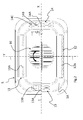
Fig. 7 , it schematically shows the direction of the air flow within the interspace 6: thefan 7 generates anair flow 16 which is concordant with the direction of rotation of the fan itself; as shown in the illustrated example, both thefan 7 and theair flow 16 circulating within theinterspace 5 rotate clockwise. - De facto, the direction of rotation of the fan is of little importance; as a matter of fact, the
air flow 16 may be either concordant with or discordant from (whether clockwise or counterclockwise) the direction of rotation of the fan depending on the type of blades fitted to the fan; all the attention should be focused, as will be discussed hereafter, on the direction of rotation of the air flow within theinterspace 6. - In
Fig. 7 , the dashed lines outline the sets ofoutlet holes bulkhead 5. - Referring also to
Fig. 2 , a first advantageous feature can be found in the fact that saidbulkhead 5 is preferably a plate, in particular a metal plate, and that the various sets of holes are distributed asymmetrically and discontinuously along theperimetric edge 5A of thebulkhead 5; the total areas of at least one pair of sets of holes adjacent to opposite sides of the bulkhead are different. - The term "total area" refers to the sum of all the areas of the single holes adjacent to one side of the
bulkhead 5. - In other words, the air passage area obtained by summing up the areas of all the
upper holes 11 is different from that of thelower holes 12, and the air passage area obtained by summing up the areas of all the left-hand side holes 13 is different from that of the right-hand side holes 14. - By observing
Figs. 2 ,3 and 4 it is possible to notice an important advantageous feature of the present invention: theperimetric edge 5A where the apertures are provided is inclined relative to thebottom plane 5B of thebulkhead 5; it thus creates an inclined perimetric annular band that extends around thebottom 5B of thebulkhead 5, which includes theaperture 10 for letting the air flow towards the fan. Of course, it is unimportant whether saidedge 5A is continuous or discontinuous, provided that the outlet section of the apertures (or sets of holes) is inclined relative to the plane of the bulkhead 5: in the latter case, in fact, it will suffice that theperimetric edge 5A includes inclined portions where the holes are provided. - More specifically, as shown more clearly in
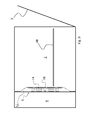
Fig. 9 , theperimetric edge 5A is inclined in a manner such that the convex side of thebulkhead 5 faces theoven chamber 2 and the concave side thereof faces the interspace 6: this causes the air flow exiting the holes to be directed first towards the chamber walls, not directly onto the foods, and more in particular it allows the fan and the resistor to be installed within theinterspace 6 without requiring additional room. - This feature improves the air flow circulation in the
chamber 2. In fact, in its first path within thechamber 2, the extremely hot air exiting through the sets ofholes chamber 2, and then it propagates towards the centre of thechamber 2. After having lapped the foods, the air flow is drawn back to the fan through thegrid 10. - The air flow exiting the holes is therefore directed first towards the walls of the
chamber 2 and only in a second time towards the foods. - According to a particularly advantageous aspect, tests have shown that it is useful in terms of air distribution to relate the total area of the upper set of
holes 11 with that of the lower set ofholes 12 so that the latter is about twice as large as the former. The reason for this is that, since hot air tends to go up, it is better to output a bigger flow from below, while however not eliminating the air flow from above, which will thus get mixed with the upward flow to ensure a more uniform hot air distribution in thechamber 5. - It has also been observed at experimental level that, if the
air flow 16 within theinterspace 6 rotates clockwise (watching the oven from the side of the door 3), the air distribution can advantageously be made more uniform by providing that the total area of the left-hand side set ofholes 13 is about half the total area of the right-hand side set ofholes 14. - Tests have shown that the best results are obtained when the sums of the total areas of the two pairs of sets of holes (
upper set 11 andlower set 12, left-hand side set 13 and right-hand side set 14) are about the same. - Of course, if the
air flow 16 within theinterspace 6 rotates counterclockwise, it will be advantageous to provide that the total area of the right-hand side set ofholes 14 is about half the total area of the left-hand side set ofholes 13. - The disproportion among the different hot air flows entering the
chamber 2 through theholes grid 10 of thefan 7, determines a better distribution of the hot air flow in thechamber 5, resulting in an actual observed improvement of the cooking of foods placed indifferent dripping pans 4B e 4C. - A further advantageous feature, the effect of which is to increase the turbulence (and therefore the distribution) of the hot air in the
chamber 2, consists in the use of a combination ofcircular holes holes holes 14C. - More specifically, the four sets of
holes holes 11 consists of a first row of four holes close together and a second row of four holes close together located at a distance from the first row, theholes 11A of both rows being all circular in shape. - The opposite lower set of
holes 12 also consists ofcircular holes 12A arranged in one row. - The two lateral sets of
holes circular holes holes flow 16 rotates clockwise) additionally comprises four short slottedholes 14C. - Of course, as aforementioned, the sets of holes may be replaced with single apertures, so long as the above-described area asymmetry is observed, as in the example shown in
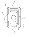
Fig. 8 , wherein by way of example theholes apertures side apertures - It should be pointed out that in this case as well (as for the above-described sets of holes), the apertures 110,120,130 and 140 are provided on the
peripheral edge 5A of thebulkhead 5, which is inclined relative to the plane in which thebulkhead 5 lies, coinciding with theplane 5B that represents the central portion of the bulkhead. - Although the
bulkhead 5 has been described above in combination with anoven 1 according to a basic configuration, it may be installed into any type of ventilated oven for providing the aforementioned effects and for obtaining the resulting advantages in multilevel cooking, which is made possible by the uniform temperature achieved in the chamber. - A particular type of oven in which the
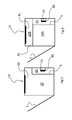
bulkhead 5 exerts particularly advantageous effects is the one shown inFigs. 5 and 6 in two different operating conditions. - With reference to
Fig. 6 , it can be observed that thisoven 10, just like theoven 1, comprises afan 70, anelectric resistor 80 adapted to heat the air drawn by thefan 70, and abulkhead 5 like the one described above, which separates achamber 20 from aninterspace 60 wherein the air drawn by the fan circulates before returning into thechamber 20 through the holes provided in thebulkhead 5, which is arranged behind thechamber 20 in the area opposite to thedoor 3. - The
oven 10 also comprises an upperelectric resistor 81 mounted to the ceiling of thechamber 20, which is normally used for the so-called "GRILL" cooking. - As shown in
Fig. 6 , thechamber 20 can be subdivided into twochambers 20A (lower) and 20B (upper) by means of aremovable septum 40, which is inserted into thechamber 20 at a predefined height; more in particular, it has been observed that the best effects on the cooking of foods are obtained when theremovable septum 40 is positioned at a height such that the volume of theupper chamber 20B is one third of the total volume of thechamber 20. - The
bulkhead 5 extends from the bottom of thechamber 20 up to a point where it meets theremovable septum 40; therefore, in the illustrated preferred configuration the height thereof is equal to approximately two thirds of the total height of thechamber 20. -
Figs. 5 and 6 show two different operating modes of the oven 10: inFig. 5 theseptum 40 is absent and the wholeinner chamber 20 is affected by the circulating air drawn by thefan 70, heated by theresistor 80 and circulated through theholes bulkhead 5. - The resulting situation is thus essentially similar to the one described previously, the only difference being that in this case the
fan 70 is not placed in the middle of thechamber 20, but it has been moved downwards, thereby further improving the distribution of the air flow, thanks to greater turbulences, for the purpose of achieving a more uniform air distribution in thechamber 20; in this regard, the upperelectric resistor 81 may be turned on or off as desired by the user. - In the configuration of
Fig. 6 theremovable septum 40 has been placed into thechamber 20, thus dividing the latter into alower chamber 20A and anupper chamber 20B: The condition of thechamber 20A is exactly the same as that of theoven 1 described previously, and therefore it will not be discussed any further; as regards theupper chamber 20B, however, when theupper resistor 81 is on it works as a GRILL chamber without ventilation. - Assuming that the
removable septum 40 in use is insulated (or anyway that it is quite thick, if made of steel, so as to limit the thermal exchange between the twochambers upper resistor 81 is off, the operation of the oven will be limited to thelower chamber 20A only, which is useful, for example, when the foods to be cooked are just a few and therefore it is not economically advisable to use the whole volume of thechamber 20, thus saving some energy. - The configuration of the
oven 10 shown inFig. 6 offers the big advantage that twochambers chambers removable septum 40 allows to keep thechambers - Of course, many alternatives or variants of the invention as described above are still possible, e.g. there may be an additional electric resistor arranged on the chamber bottom, or other additional resistors.
- Likewise, the
fan grid 10 may be replaced with any other suitable aperture, such as a simple hole or the like. - It should be pointed out that it is also possible to employ two or more fans, or even ducts for delivering the air from the fan to the various sets of holes, thereby limiting the circulation thereof to the interspace behind the chamber or even making it unnecessary.
- The present invention is advantageously applicable to ovens having a capacity of over 60 litres, preferably of approximately 70 litres, which can be embedded into a recess having a width of 60 cm and a height of 60 cm: when applied to such ovens, the present invention in fact allows to obtain a temperature distribution within the
chamber 20 such as to ensure the simultaneous cooking of foods arranged at four levels (i.e. in four dripping pans). It is apparent from the above that the present invention also offers a considerable advantage in terms of energy consumption, since it allows a larger number of foods to be cooked simultaneously in a single cooking cycle.
Claims (15)
- Ventilated oven (1,10), comprising a chamber (2,20) where foods to be cooked are placed, which is in fluidic communication with an interspace (6,60) that houses an electric resistor (8,80) and a fan (7,70) for generating a hot air flow (16) which is conveyed from the interspace (6,60) to the chamber (2,20) through apertures (11,12,13,14,110,120,130,140) provided in a dividing bulkhead (5) arranged between the chamber and the interspace (6,60),
characterized in that the apertures (11,12,13,14,110,120,130,140) are distributed asymmetrically and discontinuously along the perimetric edge (5A) of the bulkhead (5), so that in the chamber (2,20) a differentiated air flow is generated along the perimeter of the rear bulkhead of the chamber itself. - Oven (1,10) according to claim 1, wherein the bulkhead comprises a bottom (5B), and wherein the portions of the perimetric edge (5A) of the bulkhead (5) where apertures (11,12,13,14,110,120,130,140) are provided are inclined relative to the bottom (5B) of the bulkhead (5), thus directing the air flow against the walls of the chamber (2,20).
- Oven (1,10) according to claim 1 or 2, wherein the bulkhead has four sides along which there are upper apertures (11,110), lower apertures (12,120) and side apertures (13,14,130,140), the total areas of the upper (11,110) and lower (12,120) apertures being different from each other, and the total areas of the side apertures (13,14,130,140) being different from each other, in particular the sum of the total areas of the upper and lower apertures (11,12,110,120) being approximately equal to the sum of the total areas of the side apertures (13,14,130,140).
- Oven (1,10) according to any of the preceding claims, wherein the total area of the upper aperture (11,110) is approximately twice as large as the total area of the lower aperture (12,120).
- Oven (1,10) according to any of the preceding claims, wherein the total area of one side aperture (13,130) is approximately twice as large as the total area of the other aperture (14,140), the total area of the aperture immediately downstream of the upper aperture (11) in the direction of rotation of the air flow (16) within the interspace (6,60) being preferably approximately twice as large as the total area of the aperture immediately upstream of the upper aperture (11) in the direction of rotation of the air flow (16) within the interspace (6,60).
- Oven (1,10) according to any of the preceding claims, wherein the apertures comprise sets of holes (11,12,13,14).
- Oven (1,10) according to claim 6, wherein the sets of holes (13,14) comprise differently sized holes.
- Oven (1,10) according to claim 7, wherein the holes have a circular (11A,12A,13A,14A) or slotted (13B,14B,14C) shape, and wherein preferably:i) the upper set of holes (11) and the lower one comprise circular holes (11A) aligned with one another, orii) the two lateral sets of holes (13,14) comprise two side-by-side rows of holes consisting of circular holes (13A, 14A) and slotted holes (13B, 14B, 14C) arranged in parallel rows.
- Oven (1,10) according to any of the preceding claims, wherein the bulkhead comprises a grid (10), a hole or the like for letting the air flow into the interspace (6) from the chamber (2), which grid is arranged on the bottom of the bulkhead (5B), and wherein the perimetric edge (5A) is a perimetric annular band inclined relative to the bottom (5B) and extending around the latter, so that the convex face of the bulkhead faces the chamber (2,20).
- Oven (10) according to any of the preceding claims, further comprising an upper electric resistor (81) mounted to the ceiling of the chamber (20).
- Oven (1,10) according to claim 10, wherein the chamber (20) can be subdivided into two chambers (20A,20B) by means of a removable septum (40) which can be inserted into the chamber (20), said two chambers (20A,20B) being usable either simultaneously or separately by the user according to the type of foods to be cooked.
- Oven (1,10) according to claim 11, wherein said removable septum (40) is arranged at a height such that the volume of the upper chamber (20B) is one third of the total volume of the chamber (20), the bulkhead (5) preferably extending from the bottom of the chamber (20) up to the point where the removable septum (40) is inserted.
- Oven (1,10) according to claim 11 or 12, wherein the removable septum (40) is insulated, so as to limit the thermal exchange between the two chambers (20A,20B).
- Oven (1,10) according to any of the preceding claims, which has a capacity of over 60 litres, preferably of approximately 70 litres, and which can be embedded into a recess having a width of 60 cm and a height of 60 cm.
- Bulkhead (5) for an oven according to any of the preceding claims, characterized by comprising a plate (5) on which apertures (11,12,13,14,110,120,130,140) are distributed asymmetrically and discontinuously along the perimetric edge (5A) of said bulkhead (5), wherein the total areas of at least one pair of apertures (11,12,13,14,110,120,130,140) adjacent to opposite sides of the bulkhead (5) are different.
Applications Claiming Priority (1)
| Application Number | Priority Date | Filing Date | Title |
|---|---|---|---|
| ITTO20080296 ITTO20080296A1 (en) | 2008-04-15 | 2008-04-15 | VENTILATED OVEN |
Publications (2)
| Publication Number | Publication Date |
|---|---|
| EP2110612A2 true EP2110612A2 (en) | 2009-10-21 |
| EP2110612A3 EP2110612A3 (en) | 2012-09-05 |
Family
ID=40297311
Family Applications (1)
| Application Number | Title | Priority Date | Filing Date |
|---|---|---|---|
| EP09156224A Withdrawn EP2110612A3 (en) | 2008-04-15 | 2009-03-25 | Ventilated oven |
Country Status (2)
| Country | Link |
|---|---|
| EP (1) | EP2110612A3 (en) |
| IT (1) | ITTO20080296A1 (en) |
Cited By (5)
| Publication number | Priority date | Publication date | Assignee | Title |
|---|---|---|---|---|
| WO2018102082A1 (en) * | 2016-11-30 | 2018-06-07 | Illinois Tool Works Inc. | Convection system for employment with an rf oven |
| EP3546832A1 (en) * | 2018-03-27 | 2019-10-02 | Steel S.R.L. | Kitchen oven with hybrid power supply |
| CN111096686A (en) * | 2018-10-25 | 2020-05-05 | 宁波方太厨具有限公司 | Embedded oven |
| CN117297349A (en) * | 2022-06-22 | 2023-12-29 | 广东美的厨房电器制造有限公司 | Hot air hood and steam oven |
| CN117297348A (en) * | 2022-06-22 | 2023-12-29 | 广东美的厨房电器制造有限公司 | Hot air hood and microwave oven |
Citations (1)
| Publication number | Priority date | Publication date | Assignee | Title |
|---|---|---|---|---|
| EP0641976A1 (en) | 1993-09-04 | 1995-03-08 | AEG Hausgeräte GmbH | Electrical baking and roasting stove |
Family Cites Families (8)
| Publication number | Priority date | Publication date | Assignee | Title |
|---|---|---|---|---|
| GB1309078A (en) * | 1969-06-12 | 1973-03-07 | Everson Sons Ltd G R | Ovens |
| DE2950946C2 (en) * | 1979-12-18 | 1984-08-09 | Bosch-Siemens Hausgeräte GmbH, 7000 Stuttgart | Oven with fan and grill element |
| GB8802575D0 (en) * | 1988-02-05 | 1988-03-02 | Microwave Ovens Ltd | Microwave ovens & methods of defrosting food therein |
| FR2637053B1 (en) * | 1988-09-29 | 1990-11-16 | Scholtes Ets Eugen | MIXED COOKING OVEN |
| DE4224797C2 (en) * | 1992-07-27 | 1994-09-01 | Bosch Siemens Hausgeraete | oven |
| DE4304524C2 (en) * | 1993-02-15 | 2002-01-24 | Bsh Bosch Siemens Hausgeraete | oven |
| JP2004093092A (en) * | 2002-09-04 | 2004-03-25 | Toshiba Corp | Cooking device |
| KR101106636B1 (en) * | 2005-06-10 | 2012-01-18 | 삼성전자주식회사 | Oven |
-
2008
- 2008-04-15 IT ITTO20080296 patent/ITTO20080296A1/en unknown
-
2009
- 2009-03-25 EP EP09156224A patent/EP2110612A3/en not_active Withdrawn
Patent Citations (1)
| Publication number | Priority date | Publication date | Assignee | Title |
|---|---|---|---|---|
| EP0641976A1 (en) | 1993-09-04 | 1995-03-08 | AEG Hausgeräte GmbH | Electrical baking and roasting stove |
Cited By (8)
| Publication number | Priority date | Publication date | Assignee | Title |
|---|---|---|---|---|
| WO2018102082A1 (en) * | 2016-11-30 | 2018-06-07 | Illinois Tool Works Inc. | Convection system for employment with an rf oven |
| CN110313217A (en) * | 2016-11-30 | 2019-10-08 | 伊利诺斯工具制品有限公司 | Contracurrent system for radio frequency oven |
| CN110313217B (en) * | 2016-11-30 | 2022-06-24 | 伊利诺斯工具制品有限公司 | Convection Systems for RF Ovens |
| US11388787B2 (en) | 2016-11-30 | 2022-07-12 | Illinois Tool Works Inc. | Convection system for employment with an RF oven |
| EP3546832A1 (en) * | 2018-03-27 | 2019-10-02 | Steel S.R.L. | Kitchen oven with hybrid power supply |
| CN111096686A (en) * | 2018-10-25 | 2020-05-05 | 宁波方太厨具有限公司 | Embedded oven |
| CN117297349A (en) * | 2022-06-22 | 2023-12-29 | 广东美的厨房电器制造有限公司 | Hot air hood and steam oven |
| CN117297348A (en) * | 2022-06-22 | 2023-12-29 | 广东美的厨房电器制造有限公司 | Hot air hood and microwave oven |
Also Published As
| Publication number | Publication date |
|---|---|
| ITTO20080296A1 (en) | 2009-10-16 |
| EP2110612A3 (en) | 2012-09-05 |
Similar Documents
| Publication | Publication Date | Title |
|---|---|---|
| RU2660074C2 (en) | Air-based fryer pan | |
| US8113191B2 (en) | Flame tamers and arrangement thereof for barbeque grills | |
| CN102216690B (en) | Oven with dual fan convection performance distributor | |
| EP2110612A2 (en) | Ventilated oven | |
| CN108720650B (en) | Food cooking equipment | |
| KR101207641B1 (en) | Heating cooker | |
| WO2006025133A1 (en) | Heating cooking apparatus | |
| CN108095567A (en) | Cooking apparatus | |
| WO2012062679A1 (en) | Forced convection oven | |
| EP3425286B1 (en) | A cooking device and an operation method thereof | |
| CN216907658U (en) | Air fryer | |
| CN218870095U (en) | Cooking utensil | |
| KR20160082349A (en) | Steam plate for direct fire grilled | |
| EP3770511B1 (en) | Electric convection cooking oven | |
| CN216907657U (en) | Air fryer | |
| JP5377133B2 (en) | Cooker | |
| JP5377132B2 (en) | Cooker | |
| CN216907659U (en) | Air fryer | |
| EP2301397A1 (en) | Flame tamers and arrangement thereof for barbeque grills | |
| KR20040071022A (en) | cooking unit | |
| EP1739362A2 (en) | Domestic oven with air circulation system | |
| CN224193320U (en) | Cooking utensils | |
| JP6423479B2 (en) | Electric heater for cooking | |
| CN216293752U (en) | Evaporate roast inner bag structure and evaporate roast all-in-one | |
| CN224112515U (en) | A uniformly heated air duct baffle structure |
Legal Events
| Date | Code | Title | Description |
|---|---|---|---|
| PUAI | Public reference made under article 153(3) epc to a published international application that has entered the european phase |
Free format text: ORIGINAL CODE: 0009012 |
|
| AK | Designated contracting states |
Kind code of ref document: A2 Designated state(s): AT BE BG CH CY CZ DE DK EE ES FI FR GB GR HR HU IE IS IT LI LT LU LV MC MK MT NL NO PL PT RO SE SI SK TR |
|
| AX | Request for extension of the european patent |
Extension state: AL BA RS |
|
| PUAL | Search report despatched |
Free format text: ORIGINAL CODE: 0009013 |
|
| AK | Designated contracting states |
Kind code of ref document: A3 Designated state(s): AT BE BG CH CY CZ DE DK EE ES FI FR GB GR HR HU IE IS IT LI LT LU LV MC MK MT NL NO PL PT RO SE SI SK TR |
|
| AX | Request for extension of the european patent |
Extension state: AL BA RS |
|
| RIC1 | Information provided on ipc code assigned before grant |
Ipc: F24C 15/32 20060101AFI20120802BHEP |
|
| STAA | Information on the status of an ep patent application or granted ep patent |
Free format text: STATUS: THE APPLICATION IS DEEMED TO BE WITHDRAWN |
|
| 18D | Application deemed to be withdrawn |
Effective date: 20121002 |