EP2107975B1 - Verfahren zur herstellung einer dichtungsanordnung, insbesondere für ein kraftfahrzeug, und eine solche dichtungsanordnung - Google Patents
Verfahren zur herstellung einer dichtungsanordnung, insbesondere für ein kraftfahrzeug, und eine solche dichtungsanordnung Download PDFInfo
- Publication number
- EP2107975B1 EP2107975B1 EP08735491A EP08735491A EP2107975B1 EP 2107975 B1 EP2107975 B1 EP 2107975B1 EP 08735491 A EP08735491 A EP 08735491A EP 08735491 A EP08735491 A EP 08735491A EP 2107975 B1 EP2107975 B1 EP 2107975B1
- Authority
- EP
- European Patent Office
- Prior art keywords
- sealing element
- sealing
- carrier
- injection
- window pane
- Prior art date
- Legal status (The legal status is an assumption and is not a legal conclusion. Google has not performed a legal analysis and makes no representation as to the accuracy of the status listed.)
- Not-in-force
Links
Images

Classifications
-
- B—PERFORMING OPERATIONS; TRANSPORTING
- B60—VEHICLES IN GENERAL
- B60J—WINDOWS, WINDSCREENS, NON-FIXED ROOFS, DOORS, OR SIMILAR DEVICES FOR VEHICLES; REMOVABLE EXTERNAL PROTECTIVE COVERINGS SPECIALLY ADAPTED FOR VEHICLES
- B60J10/00—Sealing arrangements
- B60J10/70—Sealing arrangements specially adapted for windows or windscreens
- B60J10/74—Sealing arrangements specially adapted for windows or windscreens for sliding window panes, e.g. sash guides
- B60J10/78—Sealing arrangements specially adapted for windows or windscreens for sliding window panes, e.g. sash guides adjacent to corner pieces, mirror supports or quarter windows
-
- B—PERFORMING OPERATIONS; TRANSPORTING
- B60—VEHICLES IN GENERAL
- B60J—WINDOWS, WINDSCREENS, NON-FIXED ROOFS, DOORS, OR SIMILAR DEVICES FOR VEHICLES; REMOVABLE EXTERNAL PROTECTIVE COVERINGS SPECIALLY ADAPTED FOR VEHICLES
- B60J10/00—Sealing arrangements
- B60J10/70—Sealing arrangements specially adapted for windows or windscreens
Definitions
- the present invention relates to a method for producing a sealing arrangement, in particular for a motor vehicle, wherein the sealing arrangement comprises a first sealing element, a second sealing element and a carrier.
- the invention further relates to such a sealing arrangement.
- the gasket comprises a crosspiece which divides the window frame of the door of a motor vehicle into two areas in such a way that a fixed window pane and a movable window pane are received.
- the seal also includes a sealing profile, a separation support and a web made of hard rubber, metal or plastic. Both in the sealing profile and in the separation support channels are introduced, on the one hand record the movable window and on the other hand, the fixed window.
- the sealing profile is attached to the web in a form-fitting manner, and then the separating support is integrally molded onto the sealing profile and the web.
- the sealing profile is fastened to the web and then introduced into a casting mold together with the stationary window pane. Then the separation support is cast.
- This fastener has a metal bracket and a U-shaped plastic part forming a groove into which a metal sheet is inserted. Between the plastic part and the metal bracket cavities are formed, which are ejected and then vulcanized.
- a trim strip for a motor vehicle which comprises a profile strip which is positively connected to a glass guide channel, and an elastomeric ring which is integrally connected to the profile strip comprises.
- the profile strip is inserted into a casting mold and then with ejected an elastomeric material.
- the window guide channel is positively inserted into a channel formed by the profile strip.
- the invention has for its object to provide a method for producing a seal assembly, in particular for a motor vehicle, specify, so that the seal assembly can be produced in a simple manner in a few steps.
- the method according to the invention is based on the knowledge of positioning the first sealing element together with the carrier in the injection mold in such a way that a cavity defining the shape of the second sealing element arises or remains and subsequently the injection molding compound is introduced into the cavity in such a way that the second sealing element is formed and at the same time connected to the carrier.
- This compound is preferably formed by adhesion.
- the seal assembly can be quickly and easily prepared by providing the carrier and the first, preferably extruded, sealing member in one process step.
- an additional support for the first sealing element in its position relative to the carrier can be made possible by the shape of the second sealing element.
- the injection-molding compound can also be introduced in such a way that, in addition to a cohesive connection of the carrier and the second sealing element to be created, at the same time a cohesive connection with the first sealing element is produced. To this Way, an additional fixation of the elements of the seal assembly is created.
- the seal assembly produced by the method according to the invention is used in particular for holding, guiding and sealing a movable and a fixed window pane of a motor vehicle door.
- an elastomeric material is preferably used as an injection molding.
- a mold core which determines the shape of the second sealing element is positioned in the injection mold.
- the injection molding process can also be used to form a suitable receiving channel for later fixing a preferably fixed window.
- the channel can be formed with a correspondingly shaped inner wall, so that the window can be inserted into the channel, but can not easily pull out. This is advantageously achieved in that the inner wall has elevations and / or projections.
- the mandrel is also applied at least in sections to the carrier.
- the carrier and the cavity or the sealing element extends along a longitudinal direction.
- the mold core which likewise advantageously also extends along this longitudinal direction, can be applied in sections or at points to the carrier.
- the carrier is held in addition to the mold core in the injection mold.
- a shaped core that is shaped variably along the longitudinal direction when viewed in cross section between the adjoining sections makes it possible to form a suitable channel for receiving the window pane later.
- these contact portions of the mandrel are spaced equidistantly in the longitudinal direction.
- a correspondingly shaped outer surface of the mold core allows the formation of a survey or a stop for the introduced into the channel window or serves to form a suitably shaped base of the receiving channel.
- the injection-molding compound is introduced in such a way that the second sealing element is additionally connected to the first sealing element.
- an additional fixation of the first sealing element to the carrier can be achieved. It is created in a compact sealing arrangement with secure mutual support of the individual components.
- the positioning of the first sealing element and the carrier in the injection mold is advantageously achieved by attaching the first sealing element to the carrier.
- This attachment of the first sealing element to the carrier is preferably carried out by positive engagement, for example on at least one leg of the carrier.
- the first sealing element can be fixed in a form-fitting manner in the gap resulting from the shape of the support.
- a holding unit for holding the carrier and / or the first sealing element is positioned in the cavity.
- the holding unit can be positioned in the region of the receiving channel. It may be a holding unit extending along the longitudinal direction of the injection mold over the entire length or a holding unit in the form of a slide, which is carried along the longitudinal direction of the injection mold during the injection of the injection molding, can be used.
- the sealing arrangement according to the invention comprises a first sealing element, a second sealing element and a carrier, wherein the first sealing element is positively fixed to the carrier and the second sealing element is integrally connected by injection molding with the carrier.
- this seal assembly is made by the method described above.
- a sealing arrangement produced in this way makes use of the advantages of the method according to the invention.
- the carrier comprises an outer side and an inner side, wherein the first sealing element is attached to the inside and the second sealing element to the outside.
- This embodiment can be easily with a cross-section Realize H, L or U-shaped carrier.
- the carrier comprises a recess for the form-fitting engagement of a projection of the first sealing element.
- the carrier extends along a longitudinal direction and the second sealing element has a longitudinally variable cross-section.
- this variable cross-section can be caused by the above-mentioned mandrel for forming the receiving channel.
- the second sealing element along the longitudinal direction can be connected in sections cohesively with the first sealing element.
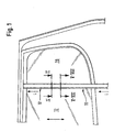
- Fig. 1 shows a view of several sealing profiles of a motor vehicle door.
- One of these sealing profiles forms the seal arrangement 10 explained in detail below for sealing and guiding a first window pane 12 and for sealing and holding a second window pane 16.
- the first window pane 12 is, as indicated by the arrow in FIG Fig. 1 indicated, raised and lowered, whereas the second window pane 16 is fixed.
- the sealing arrangement 10 forms a kind of holding / sealing web between the two window panes 12, 16.
- the seal assembly 10 each have a first extruded sealing member 20, a second injection-molded sealing member 50 and a carrier 90.
- the first extruded sealing element is separate in Fig. 3 shown.
- Fig. 4 shows the carrier 90 alone.
- the first sealing element 20 is used for guiding, holding and sealing the first window pane 12.
- the second sealing element 50 serves for holding and sealing the second window pane 16.
- the first window pane 12 has an inner surface 13, an outer surface 14 and an end face 15.
- the second window pane 16 has an inner surface 17, an outer surface 18 and an end surface 19.
- the sealing section 30 comprises in each case three sealing lips 32, 34, 36, which are each provided with a flock 37.
- the sealing lip 32 comes in the later mounting position sealingly against the inner surface 13, the sealing lip 34 sealingly against the outer surface 14 and the sealing lip 36 to lie sealingly on the end face 15.
- the flocking layer 37 allows a friction-reduced guidance of the window pane 12 perpendicular to the plane of the drawing Fig. 5 to 8 ,
- the fastening section 40 has a base 42 in the connection region of the sealing section 30. From the base 42 protrude projections in the form of two locking legs 44, 46, which allow a form-liquid fixing of the first sealing member 20 to the carrier 90.
- the sealing section 30 has two grooves 38, 39 (see FIG Fig. 3 ). Thus, the two leg-like portions of the sealing portion 30 can be moved towards each other to some extent, so as to allow easier positive fastening.
- the carrier 90 is according to the 2 and 4 to 8 (see in particular Fig. 4 H-shaped and comprises a central web 92 with a first side surface 94 and a second side surface 96. Further, the carrier 90 comprises two substantially perpendicular to the web 92 connected flanges 100, 110. The from the two flanges 100, 110 and the carrier 92 formed carrier 90 is integrally formed.
- the flange 100 has an outer side 102, an inner side 104 and an end face 106.
- the recess 108 is provided in the region of the inner side 104.
- the flange 110 accordingly has an outer side 112, an inner side 114 and an end face 116.
- the recess 118 is provided on the inner side 114.
- the second sealing element 50 produced according to the method to be explained below has an inner surface 56, which is firmly bonded to the flanges 100, 110, and an outer surface 54.
- the outer surface 54 and the inner surface 56 form an outline surface 52 of the second seal member 50.
- the second sealing element 50 comprises a first fastening section 70, which is fastened in a material-locking manner to the flange 100, and a second fastening section 72, which is fastened in a material-locking manner on the flange 110.
- the second sealing element 50 also has a channel 80 for receiving the second window pane 16.
- the regions of the second sealing element 50 surrounding the channel 80 thus serve at the same time as a sealing section 60.
- This sealing section 60 is configured in such a way that the second window pane 16 can be inserted into the channel 80 and is sufficiently sealed and permanently fixed there by the sealing section 60.
- the window pane 16 is held on the carrier 90.
- the channel 80 along the longitudinal direction L of the seal assembly 10 has a variable in cross-section elevation 84.
- This elevation 84 forms a base 82 of the channel 80.
- the elevation 84 lies completely on the side surface 96 of the carrier 90.
- the height of the elevation 84 varies along the longitudinal direction L. This shape of the elevation 84 results from the manufacturing method explained in more detail below.
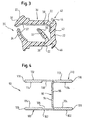
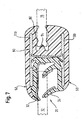
- an injection mold 120 with two tool parts 130, 140 is used (see Fig. 2 ).
- the simplicity Half was in the Fig. 5 to 8 omitted the representation of the injection mold 120 and in particular the tool parts 130, 140.
- the injection molding tool 120 or the tool parts 130, 140 are substantially the same as in FIG Fig. 2 trained and arranged.
- the tool parts 130, 140 each have an inner surface 132, 142 and a projection 134, 144.
- the inner surfaces 132, 142 provide a cavity.
- Tool parts 130, 140 with differently shaped inner surfaces 132, 142 can be used to selectively achieve a material-bonded connection of the second sealing element 50 to the first sealing element 20.
- the projections 134, 144 may also be grooved (see Fig. 5 ) to avoid expulsion of the displaced air at this point.
- the injection molding tool 120 comprises a mold core 150 having an outer surface 152 for forming the channel 80 and the elevation 84.
- the first sealing element 20 is fastened in a form-fitting manner to the carrier 90.
- the two legs of the sealing portion 30 are slightly pressed together via the grooves 38, 39 and the first sealing element 20 is pressed into the free space formed by the flanges 100, 110 and the web 92.
- the outside of the base 42 contacts the first side surface of the web 92 at least in sections, and the two locking legs 44, 46 engage in the recesses 108, 118.
- the first sealing element 20 is fixed in a form-fitting manner to the carrier 90.
- This assembly is now positioned within the injection mold 120 in the cavity in a predetermined position so that the remaining cavity has the predetermined shape of the second seal member 50 to be made.
- the original cavity bounded by the inner surfaces 132, 142 is reduced by the volume of the carrier 90 and the first sealing member 20.
- 90 on the one hand contributes to the first sealing member 20, which at least partially sealingly with the sealing lips 32, 34 against the inner surfaces 132, 142 of the tool parts 130, 140.
- the two projections 134, 144 of the tool parts 130, 140 also ensure this sealing contact.
- a holding unit or a slide can alternatively be provided be positioned in the cavity in the in the Fig. 5 to 8 indicated position of the later window pane 12.
- the holding unit has suitable dimensions, in particular with respect to the width, so that the first sealing element 20 and in particular the sealing portion 30 with the sealing lips 32, 34 sufficiently strong to the outer surfaces 102, 112 and the end faces 106, 116 of the flanges 100, 110 are pressed, so that the injection molding material fills only the predetermined cavity.
- a mandrel 150 co-determining the shape of a second sealing element 50 is positioned in the injection mold 120 such that the channel 80 can be formed.
- the mandrel 150 along the longitudinal direction L which corresponds to the advancing direction of the injection molding process, a variable cross section, so that the elevation 84 can be formed.
- the mold core 150 along the longitudinal direction L is viewed only in sections or at points on the side surface 96.
- the injection molding compound After complete introduction of the injection molding compound and formation of the second sealing element 50 along the desired length, the injection molding compound is vulcanized, and the finished sealing arrangement 10 can be removed from the injection molding tool 120.
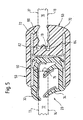
- FIGS. 2 and 5 to 8 essentially in the form of the second sealing element 50 and its possible connection to the first sealing element 20
- Fig. 5 the cohesive connection of the second sealing element 50 to the first sealing element 20 in the region of the sealing lips 32, 34 shaped differently.
- the sealing lips 32, 34 have on their outer side grooves for engagement with the correspondingly shaped projections 134, 144 of the tool parts 130, 140.
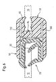
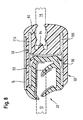
- Fig. 6 shows another alternative connection.
- the sealing lips 32, 34 are largely over-injected with the injection molding compound.
- an improved attachment of the sealing elements 20, 50 with each other and on the carrier 90 can be achieved.
- the second sealing element has a glued-on panel 74.
- the described method for producing the sealing arrangement 10 is characterized in particular by the fact that the two sealing elements 20, 50 can be connected in a simple manner to the carrier 90, in this way a complex sealing arrangement 10 for holding and sealing both the movable window pane 12 and the stationary window pane 16 can be produced in a method comprising a few steps. Since only one operation is required, a reduction in time and personnel expenses is achieved. As a result of the injection molding process, a suitable and permanent attachment of the second sealing element 50 to the carrier 90 is provided. Furthermore, the subsequent assembly of carrier 90 and the sealing elements 20, 50 is not necessary until final assembly. Thus, the seal assembly 10 can already be delivered ready made and mounted in a simple manner on the vehicle door.
Landscapes
- Engineering & Computer Science (AREA)
- Mechanical Engineering (AREA)
- Injection Moulding Of Plastics Or The Like (AREA)
- Moulds For Moulding Plastics Or The Like (AREA)
- Insulation, Fastening Of Motor, Generator Windings (AREA)
- Sealing Material Composition (AREA)
- Seal Device For Vehicle (AREA)
Priority Applications (1)
| Application Number | Priority Date | Filing Date | Title |
|---|---|---|---|
| PL08735491T PL2107975T3 (pl) | 2007-03-30 | 2008-03-26 | Sposób wytwrarzania zestawu uszczelniającego, zwłaszcza do pojazdów samochodowych, i taki zestaw uszczelniający |
Applications Claiming Priority (2)
| Application Number | Priority Date | Filing Date | Title |
|---|---|---|---|
| DE102007015464A DE102007015464A1 (de) | 2007-03-30 | 2007-03-30 | Verfahren zur Herstellung einer Dichtungsanordnung, insbesondere für ein Kraftfahrzeug, und eine solche Dichtungsanordnung |
| PCT/EP2008/053579 WO2008119707A1 (de) | 2007-03-30 | 2008-03-26 | Verfahren zur herstellung einer dichtungsanordnung, insbesondere für ein kraftfahrzeug, und eine solche dichtungsanordnung |
Publications (2)
| Publication Number | Publication Date |
|---|---|
| EP2107975A1 EP2107975A1 (de) | 2009-10-14 |
| EP2107975B1 true EP2107975B1 (de) | 2010-12-29 |
Family
ID=39521957
Family Applications (1)
| Application Number | Title | Priority Date | Filing Date |
|---|---|---|---|
| EP08735491A Not-in-force EP2107975B1 (de) | 2007-03-30 | 2008-03-26 | Verfahren zur herstellung einer dichtungsanordnung, insbesondere für ein kraftfahrzeug, und eine solche dichtungsanordnung |
Country Status (6)
| Country | Link |
|---|---|
| EP (1) | EP2107975B1 (pl) |
| AT (1) | ATE493288T1 (pl) |
| DE (2) | DE102007015464A1 (pl) |
| ES (1) | ES2354512T3 (pl) |
| PL (1) | PL2107975T3 (pl) |
| WO (1) | WO2008119707A1 (pl) |
Family Cites Families (7)
| Publication number | Priority date | Publication date | Assignee | Title |
|---|---|---|---|---|
| FR2624191B1 (pl) * | 1987-12-04 | 1993-10-22 | Mesnel Ets | |
| JPH085092B2 (ja) * | 1991-09-25 | 1996-01-24 | 豊田合成株式会社 | ウエザストリップの製造方法 |
| DE19543971C2 (de) * | 1995-11-25 | 1998-06-04 | Mecano Rapid Gmbh | Element zur Befestigung einer Profildichtung |
| US5702148A (en) * | 1996-02-29 | 1997-12-30 | The Standard Products Company | Exterior decorative surround molding module |
| TW466190B (en) * | 1999-07-23 | 2001-12-01 | Toyoda Gosei Kk | Weather resistant strip and process for manufacturing the same |
| DE10349650A1 (de) * | 2003-10-20 | 2005-05-19 | Mayser Gmbh & Co. Kg | Profilanordnung für Einklemmschutz und Spritzgusswerkzeug |
| WO2006067622A1 (en) * | 2004-12-23 | 2006-06-29 | Gdx Automotive Rehburg Gmbh & Co. Kg | Sealing or guiding assemblies and methods of making them |
-
2007
- 2007-03-30 DE DE102007015464A patent/DE102007015464A1/de not_active Withdrawn
-
2008
- 2008-03-26 PL PL08735491T patent/PL2107975T3/pl unknown
- 2008-03-26 WO PCT/EP2008/053579 patent/WO2008119707A1/de not_active Ceased
- 2008-03-26 EP EP08735491A patent/EP2107975B1/de not_active Not-in-force
- 2008-03-26 ES ES08735491T patent/ES2354512T3/es active Active
- 2008-03-26 AT AT08735491T patent/ATE493288T1/de active
- 2008-03-26 DE DE502008002128T patent/DE502008002128D1/de active Active
Also Published As
| Publication number | Publication date |
|---|---|
| WO2008119707A1 (de) | 2008-10-09 |
| DE502008002128D1 (de) | 2011-02-10 |
| ATE493288T1 (de) | 2011-01-15 |
| EP2107975A1 (de) | 2009-10-14 |
| DE102007015464A1 (de) | 2008-10-02 |
| PL2107975T3 (pl) | 2011-05-31 |
| ES2354512T3 (es) | 2011-03-15 |
Similar Documents
| Publication | Publication Date | Title |
|---|---|---|
| DE69508132T2 (de) | Dichtungsleisteanordnung | |
| DE60018608T2 (de) | Anfügen einer autoscheibe an ein anschlusselement | |
| DE19531167C2 (de) | Kraftfahrzeug-Dichtungsprofil | |
| DE69311456T2 (de) | Formteil für Tür | |
| EP2463134B1 (de) | Dichtungsvorrichtung für eine Scheibeneinheit und dazugehöriges Herstellungsverfahren | |
| DE69409432T2 (de) | Scheibenführung für verschiebbare Fahrzeugscheiben | |
| EP1935694B1 (de) | Dichtungsprofil, insbesondere zum Abdichten einer Tür gegenüber der Karosserie eines Kraftfahrzeugs | |
| DE60320276T9 (de) | Dichtungs-, zier- oder führungsstreifen | |
| EP2310231B1 (de) | Zierprofil, insbesondere für den fensterbereich eines kraftfahrzeugs | |
| DE10159251C1 (de) | Aufnahmerahmen für eine stationäre Fensterscheibe | |
| EP2129506B1 (de) | Verfahren zur herstellung einer dichtungsanordnung, insbesondere für ein kraftfahrzeug, mit einem dichtungselement und einem träger sowie eine solche dichtungsanordnung | |
| DE102007018792B4 (de) | Verfahren zur Herstellung einer Dichtung sowie Vorrichtung zur Herstellung einer Dichtung | |
| DE10147327A1 (de) | Dachteil, insbesondere Innenhimmel für ein Fahrzeugdach, und Verfahren zu seiner Herstellung | |
| EP1946951B1 (de) | Verfahren zur Herstellung einer Dichtung, insbesondere für ein Kraftfahrzeug, und eine solche Dichtung | |
| EP2107975B1 (de) | Verfahren zur herstellung einer dichtungsanordnung, insbesondere für ein kraftfahrzeug, und eine solche dichtungsanordnung | |
| EP0155641B1 (de) | Vorrichtung zur Führung und Halterung einer beweglichen Fensterscheibe im Fensterrahmen eines Kraftfahrzeugs | |
| DE102017211291B4 (de) | Fensterschachtleistenanordnung sowie Verfahren zum Herstellen einer Fensterschachtleistenanordnung | |
| DE10137958C2 (de) | Karosseriefeste Führungsschiene für ein verstellbares Element einer Fahrzeugkarosserie | |
| EP1737692B1 (de) | Verfahren zum herstellen eines dicht-oder zierstreifens, insbesondere für ein kraftfahrzeug, sowie ein solcher dicht-oder zierstreifen | |
| DE102018123664B3 (de) | Gitterverbund für eine Luftöffnung | |
| DE102015015750B3 (de) | Wasserfangleiste zur Anordnung an einer A-Säule eines Kraftfahrzeugs, Kraftfahrzeug und Verfahren zum Fertigen einer Wasserfangleiste | |
| DE69504161T2 (de) | Verfahren zur Herstellung eines mit metallischer Armatur ausgerüsteten, extrudierten Dichtungsprofils für Kraftfahrzeuge. | |
| EP4277834B1 (de) | Dachspoiler | |
| DE102024116844A1 (de) | Dichtungsanordnung für ein Schiebefenster und Verfahren zu deren Herstellung | |
| DE102015218405A1 (de) | Verbundbauteil zur Führung und Abdichtung von Strukturelementen im Bereich einer Fahrzeugtür |
Legal Events
| Date | Code | Title | Description |
|---|---|---|---|
| PUAI | Public reference made under article 153(3) epc to a published international application that has entered the european phase |
Free format text: ORIGINAL CODE: 0009012 |
|
| 17P | Request for examination filed |
Effective date: 20090212 |
|
| AK | Designated contracting states |
Kind code of ref document: A1 Designated state(s): AT BE BG CH CY CZ DE DK EE ES FI FR GB GR HR HU IE IS IT LI LT LU LV MC MT NL NO PL PT RO SE SI SK TR |
|
| RIN1 | Information on inventor provided before grant (corrected) |
Inventor name: HOFMAIER, STEFAN Inventor name: BURGER, REINHOLD |
|
| 17Q | First examination report despatched |
Effective date: 20100303 |
|
| DAX | Request for extension of the european patent (deleted) | ||
| GRAP | Despatch of communication of intention to grant a patent |
Free format text: ORIGINAL CODE: EPIDOSNIGR1 |
|
| GRAS | Grant fee paid |
Free format text: ORIGINAL CODE: EPIDOSNIGR3 |
|
| GRAA | (expected) grant |
Free format text: ORIGINAL CODE: 0009210 |
|
| AK | Designated contracting states |
Kind code of ref document: B1 Designated state(s): AT BE BG CH CY CZ DE DK EE ES FI FR GB GR HR HU IE IS IT LI LT LU LV MC MT NL NO PL PT RO SE SI SK TR |
|
| REG | Reference to a national code |
Ref country code: GB Ref legal event code: FG4D Free format text: NOT ENGLISH |
|
| REG | Reference to a national code |
Ref country code: CH Ref legal event code: EP |
|
| REG | Reference to a national code |
Ref country code: IE Ref legal event code: FG4D Free format text: LANGUAGE OF EP DOCUMENT: GERMAN |
|
| REF | Corresponds to: |
Ref document number: 502008002128 Country of ref document: DE Date of ref document: 20110210 Kind code of ref document: P |
|
| REG | Reference to a national code |
Ref country code: DE Ref legal event code: R096 Ref document number: 502008002128 Country of ref document: DE Effective date: 20110210 |
|
| REG | Reference to a national code |
Ref country code: ES Ref legal event code: FG2A Effective date: 20110303 |
|
| REG | Reference to a national code |
Ref country code: RO Ref legal event code: EPE |
|
| REG | Reference to a national code |
Ref country code: NL Ref legal event code: VDEP Effective date: 20101229 |
|
| PG25 | Lapsed in a contracting state [announced via postgrant information from national office to epo] |
Ref country code: LT Free format text: LAPSE BECAUSE OF FAILURE TO SUBMIT A TRANSLATION OF THE DESCRIPTION OR TO PAY THE FEE WITHIN THE PRESCRIBED TIME-LIMIT Effective date: 20101229 |
|
| LTIE | Lt: invalidation of european patent or patent extension |
Effective date: 20101229 |
|
| PG25 | Lapsed in a contracting state [announced via postgrant information from national office to epo] |
Ref country code: SI Free format text: LAPSE BECAUSE OF FAILURE TO SUBMIT A TRANSLATION OF THE DESCRIPTION OR TO PAY THE FEE WITHIN THE PRESCRIBED TIME-LIMIT Effective date: 20101229 Ref country code: HR Free format text: LAPSE BECAUSE OF FAILURE TO SUBMIT A TRANSLATION OF THE DESCRIPTION OR TO PAY THE FEE WITHIN THE PRESCRIBED TIME-LIMIT Effective date: 20101229 Ref country code: CY Free format text: LAPSE BECAUSE OF FAILURE TO SUBMIT A TRANSLATION OF THE DESCRIPTION OR TO PAY THE FEE WITHIN THE PRESCRIBED TIME-LIMIT Effective date: 20101229 Ref country code: FI Free format text: LAPSE BECAUSE OF FAILURE TO SUBMIT A TRANSLATION OF THE DESCRIPTION OR TO PAY THE FEE WITHIN THE PRESCRIBED TIME-LIMIT Effective date: 20101229 Ref country code: SE Free format text: LAPSE BECAUSE OF FAILURE TO SUBMIT A TRANSLATION OF THE DESCRIPTION OR TO PAY THE FEE WITHIN THE PRESCRIBED TIME-LIMIT Effective date: 20101229 Ref country code: LV Free format text: LAPSE BECAUSE OF FAILURE TO SUBMIT A TRANSLATION OF THE DESCRIPTION OR TO PAY THE FEE WITHIN THE PRESCRIBED TIME-LIMIT Effective date: 20101229 Ref country code: BG Free format text: LAPSE BECAUSE OF FAILURE TO SUBMIT A TRANSLATION OF THE DESCRIPTION OR TO PAY THE FEE WITHIN THE PRESCRIBED TIME-LIMIT Effective date: 20110329 |
|
| REG | Reference to a national code |
Ref country code: PL Ref legal event code: T3 |
|
| REG | Reference to a national code |
Ref country code: IE Ref legal event code: FD4D |
|
| PG25 | Lapsed in a contracting state [announced via postgrant information from national office to epo] |
Ref country code: EE Free format text: LAPSE BECAUSE OF FAILURE TO SUBMIT A TRANSLATION OF THE DESCRIPTION OR TO PAY THE FEE WITHIN THE PRESCRIBED TIME-LIMIT Effective date: 20101229 Ref country code: PT Free format text: LAPSE BECAUSE OF FAILURE TO SUBMIT A TRANSLATION OF THE DESCRIPTION OR TO PAY THE FEE WITHIN THE PRESCRIBED TIME-LIMIT Effective date: 20110429 Ref country code: GR Free format text: LAPSE BECAUSE OF FAILURE TO SUBMIT A TRANSLATION OF THE DESCRIPTION OR TO PAY THE FEE WITHIN THE PRESCRIBED TIME-LIMIT Effective date: 20110330 Ref country code: IS Free format text: LAPSE BECAUSE OF FAILURE TO SUBMIT A TRANSLATION OF THE DESCRIPTION OR TO PAY THE FEE WITHIN THE PRESCRIBED TIME-LIMIT Effective date: 20110429 Ref country code: NO Free format text: LAPSE BECAUSE OF FAILURE TO SUBMIT A TRANSLATION OF THE DESCRIPTION OR TO PAY THE FEE WITHIN THE PRESCRIBED TIME-LIMIT Effective date: 20110329 |
|
| REG | Reference to a national code |
Ref country code: SK Ref legal event code: T3 Ref document number: E 9375 Country of ref document: SK |
|
| REG | Reference to a national code |
Ref country code: HU Ref legal event code: AG4A Ref document number: E010621 Country of ref document: HU |
|
| PG25 | Lapsed in a contracting state [announced via postgrant information from national office to epo] |
Ref country code: NL Free format text: LAPSE BECAUSE OF FAILURE TO SUBMIT A TRANSLATION OF THE DESCRIPTION OR TO PAY THE FEE WITHIN THE PRESCRIBED TIME-LIMIT Effective date: 20101229 |
|
| BERE | Be: lapsed |
Owner name: METZELER AUTOMOTIVE PROFILE SYSTEMS G.M.B.H. Effective date: 20110331 |
|
| PG25 | Lapsed in a contracting state [announced via postgrant information from national office to epo] |
Ref country code: DK Free format text: LAPSE BECAUSE OF FAILURE TO SUBMIT A TRANSLATION OF THE DESCRIPTION OR TO PAY THE FEE WITHIN THE PRESCRIBED TIME-LIMIT Effective date: 20101229 Ref country code: IE Free format text: LAPSE BECAUSE OF FAILURE TO SUBMIT A TRANSLATION OF THE DESCRIPTION OR TO PAY THE FEE WITHIN THE PRESCRIBED TIME-LIMIT Effective date: 20101229 Ref country code: MC Free format text: LAPSE BECAUSE OF NON-PAYMENT OF DUE FEES Effective date: 20110331 |
|
| PLBE | No opposition filed within time limit |
Free format text: ORIGINAL CODE: 0009261 |
|
| STAA | Information on the status of an ep patent application or granted ep patent |
Free format text: STATUS: NO OPPOSITION FILED WITHIN TIME LIMIT |
|
| 26N | No opposition filed |
Effective date: 20110930 |
|
| PG25 | Lapsed in a contracting state [announced via postgrant information from national office to epo] |
Ref country code: MT Free format text: LAPSE BECAUSE OF FAILURE TO SUBMIT A TRANSLATION OF THE DESCRIPTION OR TO PAY THE FEE WITHIN THE PRESCRIBED TIME-LIMIT Effective date: 20101229 Ref country code: BE Free format text: LAPSE BECAUSE OF NON-PAYMENT OF DUE FEES Effective date: 20110331 |
|
| REG | Reference to a national code |
Ref country code: DE Ref legal event code: R097 Ref document number: 502008002128 Country of ref document: DE Effective date: 20110930 |
|
| REG | Reference to a national code |
Ref country code: CH Ref legal event code: PL |
|
| PG25 | Lapsed in a contracting state [announced via postgrant information from national office to epo] |
Ref country code: LI Free format text: LAPSE BECAUSE OF NON-PAYMENT OF DUE FEES Effective date: 20120331 Ref country code: CH Free format text: LAPSE BECAUSE OF NON-PAYMENT OF DUE FEES Effective date: 20120331 |
|
| PG25 | Lapsed in a contracting state [announced via postgrant information from national office to epo] |
Ref country code: LU Free format text: LAPSE BECAUSE OF NON-PAYMENT OF DUE FEES Effective date: 20110326 |
|
| REG | Reference to a national code |
Ref country code: DE Ref legal event code: R082 Ref document number: 502008002128 Country of ref document: DE Representative=s name: FLUEGEL PREISSNER KASTEL SCHOBER, DE |
|
| REG | Reference to a national code |
Ref country code: DE Ref legal event code: R081 Ref document number: 502008002128 Country of ref document: DE Owner name: COOPER STANDARD GMBH, DE Free format text: FORMER OWNER: METZELER AUTOMOTIVE PROFILE SYSTEMS GMBH, 88131 LINDAU, DE Effective date: 20131118 Ref country code: DE Ref legal event code: R082 Ref document number: 502008002128 Country of ref document: DE Representative=s name: FLUEGEL PREISSNER KASTEL SCHOBER, DE Effective date: 20131118 Ref country code: DE Ref legal event code: R082 Ref document number: 502008002128 Country of ref document: DE Representative=s name: FLUEGEL PREISSNER KASTEL SCHOBER PATENTANWAELT, DE Effective date: 20131118 Ref country code: DE Ref legal event code: R082 Ref document number: 502008002128 Country of ref document: DE Representative=s name: FLUEGEL PREISSNER SCHOBER SEIDEL PATENTANWAELT, DE Effective date: 20131118 |
|
| REG | Reference to a national code |
Ref country code: AT Ref legal event code: MM01 Ref document number: 493288 Country of ref document: AT Kind code of ref document: T Effective date: 20130326 |
|
| PG25 | Lapsed in a contracting state [announced via postgrant information from national office to epo] |
Ref country code: AT Free format text: LAPSE BECAUSE OF NON-PAYMENT OF DUE FEES Effective date: 20130326 |
|
| REG | Reference to a national code |
Ref country code: ES Ref legal event code: PC2A Owner name: COOPER STANDARD GMBH Effective date: 20141003 |
|
| REG | Reference to a national code |
Ref country code: HU Ref legal event code: HC9C Owner name: COOPER STANDARD GMBH, DE Free format text: FORMER OWNER(S): METZELER AUTOMOTIVE PROFILE SYSTEMS GMBH, DE |
|
| REG | Reference to a national code |
Ref country code: SK Ref legal event code: TC4A Ref document number: E 9375 Country of ref document: SK Owner name: COOPER STANDARD GMBH, LINDAU/BODENSEE, DE Effective date: 20141212 |
|
| REG | Reference to a national code |
Ref country code: FR Ref legal event code: PLFP Year of fee payment: 9 |
|
| REG | Reference to a national code |
Ref country code: FR Ref legal event code: PLFP Year of fee payment: 10 |
|
| PGFP | Annual fee paid to national office [announced via postgrant information from national office to epo] |
Ref country code: RO Payment date: 20170320 Year of fee payment: 10 |
|
| PGFP | Annual fee paid to national office [announced via postgrant information from national office to epo] |
Ref country code: CZ Payment date: 20170316 Year of fee payment: 10 Ref country code: HU Payment date: 20170320 Year of fee payment: 10 Ref country code: SK Payment date: 20170316 Year of fee payment: 10 Ref country code: PL Payment date: 20170316 Year of fee payment: 10 |
|
| PGFP | Annual fee paid to national office [announced via postgrant information from national office to epo] |
Ref country code: TR Payment date: 20170322 Year of fee payment: 10 |
|
| REG | Reference to a national code |
Ref country code: FR Ref legal event code: CD Owner name: COOPER STANDARD GMBH, DE Effective date: 20170831 |
|
| REG | Reference to a national code |
Ref country code: FR Ref legal event code: PLFP Year of fee payment: 11 |
|
| PG25 | Lapsed in a contracting state [announced via postgrant information from national office to epo] |
Ref country code: RO Free format text: LAPSE BECAUSE OF NON-PAYMENT OF DUE FEES Effective date: 20180326 |
|
| PG25 | Lapsed in a contracting state [announced via postgrant information from national office to epo] |
Ref country code: CZ Free format text: LAPSE BECAUSE OF NON-PAYMENT OF DUE FEES Effective date: 20180326 |
|
| REG | Reference to a national code |
Ref country code: SK Ref legal event code: MM4A Ref document number: E 9375 Country of ref document: SK Effective date: 20180326 |
|
| PG25 | Lapsed in a contracting state [announced via postgrant information from national office to epo] |
Ref country code: HU Free format text: LAPSE BECAUSE OF NON-PAYMENT OF DUE FEES Effective date: 20180327 Ref country code: SK Free format text: LAPSE BECAUSE OF NON-PAYMENT OF DUE FEES Effective date: 20180326 |
|
| PGFP | Annual fee paid to national office [announced via postgrant information from national office to epo] |
Ref country code: FR Payment date: 20190326 Year of fee payment: 12 Ref country code: GB Payment date: 20190325 Year of fee payment: 12 Ref country code: IT Payment date: 20190321 Year of fee payment: 12 |
|
| PGFP | Annual fee paid to national office [announced via postgrant information from national office to epo] |
Ref country code: DE Payment date: 20190405 Year of fee payment: 12 Ref country code: ES Payment date: 20190424 Year of fee payment: 12 |
|
| PG25 | Lapsed in a contracting state [announced via postgrant information from national office to epo] |
Ref country code: PL Free format text: LAPSE BECAUSE OF NON-PAYMENT OF DUE FEES Effective date: 20180326 |
|
| REG | Reference to a national code |
Ref country code: DE Ref legal event code: R119 Ref document number: 502008002128 Country of ref document: DE |
|
| PG25 | Lapsed in a contracting state [announced via postgrant information from national office to epo] |
Ref country code: FR Free format text: LAPSE BECAUSE OF NON-PAYMENT OF DUE FEES Effective date: 20200331 Ref country code: DE Free format text: LAPSE BECAUSE OF NON-PAYMENT OF DUE FEES Effective date: 20201001 |
|
| GBPC | Gb: european patent ceased through non-payment of renewal fee |
Effective date: 20200326 |
|
| PG25 | Lapsed in a contracting state [announced via postgrant information from national office to epo] |
Ref country code: GB Free format text: LAPSE BECAUSE OF NON-PAYMENT OF DUE FEES Effective date: 20200326 |
|
| REG | Reference to a national code |
Ref country code: ES Ref legal event code: FD2A Effective date: 20210811 |
|
| PG25 | Lapsed in a contracting state [announced via postgrant information from national office to epo] |
Ref country code: IT Free format text: LAPSE BECAUSE OF NON-PAYMENT OF DUE FEES Effective date: 20200326 |
|
| PG25 | Lapsed in a contracting state [announced via postgrant information from national office to epo] |
Ref country code: ES Free format text: LAPSE BECAUSE OF NON-PAYMENT OF DUE FEES Effective date: 20200327 |
|
| PG25 | Lapsed in a contracting state [announced via postgrant information from national office to epo] |
Ref country code: TR Free format text: LAPSE BECAUSE OF NON-PAYMENT OF DUE FEES Effective date: 20180326 |