EP2107958B1 - Spanabhebendes werkzeug - Google Patents
Spanabhebendes werkzeug Download PDFInfo
- Publication number
- EP2107958B1 EP2107958B1 EP07856036.4A EP07856036A EP2107958B1 EP 2107958 B1 EP2107958 B1 EP 2107958B1 EP 07856036 A EP07856036 A EP 07856036A EP 2107958 B1 EP2107958 B1 EP 2107958B1
- Authority
- EP
- European Patent Office
- Prior art keywords
- adjusting
- tool
- tool according
- base body
- fluid chamber
- Prior art date
- Legal status (The legal status is an assumption and is not a legal conclusion. Google has not performed a legal analysis and makes no representation as to the accuracy of the status listed.)
- Active
Links
Images
Classifications
-
- B—PERFORMING OPERATIONS; TRANSPORTING
- B23—MACHINE TOOLS; METAL-WORKING NOT OTHERWISE PROVIDED FOR
- B23B—TURNING; BORING
- B23B29/00—Holders for non-rotary cutting tools; Boring bars or boring heads; Accessories for tool holders
- B23B29/03—Boring heads
- B23B29/034—Boring heads with tools moving radially, e.g. for making chamfers or undercuttings
- B23B29/03432—Boring heads with tools moving radially, e.g. for making chamfers or undercuttings radially adjustable during manufacturing
- B23B29/03457—Boring heads with tools moving radially, e.g. for making chamfers or undercuttings radially adjustable during manufacturing by pivoting the tool carriers or by elastic deformation
-
- B—PERFORMING OPERATIONS; TRANSPORTING
- B23—MACHINE TOOLS; METAL-WORKING NOT OTHERWISE PROVIDED FOR
- B23B—TURNING; BORING
- B23B29/00—Holders for non-rotary cutting tools; Boring bars or boring heads; Accessories for tool holders
- B23B29/03—Boring heads
- B23B29/034—Boring heads with tools moving radially, e.g. for making chamfers or undercuttings
- B23B29/03403—Boring heads with tools moving radially, e.g. for making chamfers or undercuttings radially adjustable before starting manufacturing
- B23B29/03421—Boring heads with tools moving radially, e.g. for making chamfers or undercuttings radially adjustable before starting manufacturing by pivoting the tool carriers or by elastic deformation
-
- B—PERFORMING OPERATIONS; TRANSPORTING
- B23—MACHINE TOOLS; METAL-WORKING NOT OTHERWISE PROVIDED FOR
- B23C—MILLING
- B23C2270/00—Details of milling machines, milling processes or milling tools not otherwise provided for
- B23C2270/02—Use of a particular power source
- B23C2270/025—Hydraulics
-
- B—PERFORMING OPERATIONS; TRANSPORTING
- B23—MACHINE TOOLS; METAL-WORKING NOT OTHERWISE PROVIDED FOR
- B23C—MILLING
- B23C2270/00—Details of milling machines, milling processes or milling tools not otherwise provided for
- B23C2270/02—Use of a particular power source
- B23C2270/027—Pneumatics
Definitions
- the invention relates to a cutting tool according to the preamble of claim 1.
- a support member with a cutting plate is elastically arranged on a tool base body. For particular radial positioning of the support member with cutting plate adjusting means are provided.
- the distance of a part of the support member is changed to the main body of the tool.
- DE 10 2004 017 714 discloses an adjustment and adjustment system for strip-shaped blade carrier on cutting tools, such as milling cutters, with a plurality of longitudinally inclined obliquely to the longitudinal center axis incorporated grooves base body, a plurality of received in a respective groove cutter carriers, the main body axially cross-cutting, at the two ends by each a closure pin sealed channel, a longitudinally disposed in the channel separator which separates the channel in a front channel piece and a rear channel piece, and a plurality of associated with a respective blade carrier, front and rear hydraulically displaceable actuators for adjusting the cutter carrier.
- Each actuator opens at a radially outer end into a respective groove.
- a respective front actuator opens into the front channel piece and a respective rear actuator opens into the rear channel piece.
- DE 103 50 851 which is based on the preamble of claim 1, discloses a milling tool having a plurality of axially or radially outwardly open receptacles having support body, at least one opening into a bottom of the receptacle hole in which a displaceable by means of a hydraulic fluid piston is arranged, a plurality of clamped in the recordings received and with their cutting radially over the support body protruding and each attached to a knife carrier knives and at least one screw associated with a respective knife in a bore receiving the screw.
- Each receptacle points axially in Axialnuten pointing in opposite directions
- each blade carrier has a cross-sectionally T-shaped foot with two arms, wherein a respective arm engages in one of the axially opposite axial grooves.
- At least one axial groove is in fluid communication with the bore of the screw. The axial or radial position of the cutting edge of each clamped knife by operating the at least one screw hydraulically operated finely adjustable.
- the invention has for its object to provide a cutting tool of the type described in the introduction that includes an advantageous adjustment mechanism for the alignment of the support member on the body.
- the invention is based on a cutting tool with a tool carrier, which comprises a support member with a cutting plate and a base body.
- the support member is elastically connected to the base body.
- adjusting means are provided in order to position the support member with cutting plate on the body can.
- the adjusting means have a hydraulically and / or pneumatically operable adjusting element.
- the tool carrier is integrally formed with the support member and the base body.
- a tool carrier which comprises a support member with a cutting plate and a base body.
- the support member is elastically connected to the base body.
- adjusting means are provided in order to position the support member with cutting plate on the body can.
- the adjusting means comprise a hydraulically and / or pneumatically operable adjusting element.
- a comparatively sensitive adjustment or alignment possibility for the support member and the insert located thereon can be realized first.
- this can e.g. made a wear compensation of the cutting plate.
- the actuatable adjustment member may also be accommodated in a desired position, wherein due to the hydraulic and / or pneumatic actuation, a corresponding adjustment member can be arranged substantially independently of the positioning of the adjustment member at another preferred location.
- the adjusting means comprise a hydraulically movable piston.
- the piston preferably presses on the support member to specify in the elastic region whose position or orientation with respect to the base body.
- a piston can be easily guided in a suitable bore and reliably sealed with corresponding sealing means with comparatively little effort to the outside.
- the adjusting means comprise a fluid chamber filled with fluid.
- a first opening of the fluid chamber is closed by an adjusting screw with sealant.
- the adjusting screw allows the volume of the fluid chamber to be changed.
- an adjusting element for example a piston which closes a second opening of the fluid chamber, is pushed out of this opening in accordance with the change in volume when the adjusting screw is screwed in to act on the supporting element.
- the adjustment acts directly on the support member.
- an interposed mechanism to be able to realize desired gear ratios, for example via levers or a gearbox.
- the fluid chamber is formed in the base body.
- the body regularly has sufficient volume and position capabilities to accommodate the fluid chamber and openings suitable for a set screw or a setting.
- the support member e.g. for the adjustment, an adjustable abutment is provided.
- a coarse adjustment can be made, so that only a fine adjustment must be made with the hydraulic system.
- the hydraulic system can only be fine tuned, e.g. be designed in tenths.
- the fluid chamber is formed such that the adjusting element and the adjusting screw are at an angle to each other, preferably at an angle of approximately or exactly 90 °.
- Such a geometrical arrangement not only makes it comparatively easy to form a fluid chamber through two holes which meet one another, but also one achieve favorable positioning of the hydraulic parts.
- an adjusting element and an adjusting screw are axially aligned in the tool.
- an adjusting screw be provided with a displacement element, e.g. a piston element is arranged downstream, the sealing means comprises a rempliidsch.
- a simple screw e.g. a grub screw for the adjustment of the hydraulic system are used.
- the cross-sectional area of an adjusting element and an adjusting screw or a downstream sealed displacement element are coordinated so that a desired sensitive adjustment of the adjusting element via the adjusting screw is possible, in which a displacement of a displacement element by the corresponding cross-sectional differences in particular is stocky.
- a finishing tool 1 is shown.
- the finishing tool 1 comprises a base body 2 and a supporting arm 3 arranged integrally thereon.
- a shaft 4 is provided for receiving the tool in e.g. a spindle of a machine tool.
- an insert 5 is arranged by way of example via a fastening screw 6.
- the position of the support arm 3 is determined by a hydraulic system 7, which is formed in the base body 2.
- the hydraulic system 7 comprises a setting piston 8 which is displaceably guided in a bore 8a.
- a seal 8b is provided to reliably seal the piston 8 against the wall of the bore 8a.
- the hydraulic system comprises an adjusting screw 9 in a threaded bore 9a in the main body 2.
- the adjusting screw 9 presses on a piston element 10, which in a threaded bore 9 a downstream bore 10 a slidably arranged.
- a seal 10 b is provided to seal the piston member 10 to the outside to the adjusting screw 9 reliable.
- the bore 8a and the bore 10a intersect and form a fluid chamber 11 with the volumes of the respective bores 8a and 10a not occupied by the adjusting piston 8 or its seal 8b and the piston 10 or its seal 10b.
- the fluid chamber 11 is preferably filled with a hydraulic oil.
- the piston member 10 By adjusting the adjusting screw 9, in particular screwing, the piston member 10 is moved along. For adjusting the volume of the hydraulic fluid displaced thereby, the adjusting piston 8 is pushed out of the bore 8a and presses on the support arm 3.
- a re-bearing on the support arm 3 is formed as the screw 12.
- the screw 12 has, for example, a hexagon socket to make an adjustment on the support arm 3 can.
- the adjusting screw 9 can advantageously also be actuated by a hexagon socket.
- the hydraulic system 7 has a remote-controlled operation.
- the hydraulic system 7 is connected via a hydraulic line with a control system separate from the tool 1. This can be done via a separate hydraulic line.
- the hydraulic line is formed, for example, as a central channel in the finishing tool 1.
Landscapes
- Engineering & Computer Science (AREA)
- Mechanical Engineering (AREA)
- Jigs For Machine Tools (AREA)
- Cutting Tools, Boring Holders, And Turrets (AREA)
Description
- Die Erfindung betrifft ein spanabhebendes Werkzeug nach dem Oberbegriff des Anspruchs 1.
- Bei einer bekannten Ausführungsform eines spanabhebenden Werkzeugs ist an einem Werkzeug-Grundkörper ein Tragorgan mit einer Schneidplatte elastisch angeordnet. Zur insbesondere radialen Positionierung des Tragorgans mit Schneidplatte sind Justiermittel vorgesehen.
- Mit den Justiermitteln wird der Abstand eines Teils des Tragorgans zum Grundkörper des Werkzeugs verändert.
-
DE 10 2004 017 714 offenbart ein Einstell- und Verstellsystem für leistenförmige Schneidenträger an spanend arbeitenden Werkzeugen, wie Walzenfräsern, mit einem mehrere längsseitig schräg zur Längsmittenachse geneigt eingearbeitete Nuten aufweisenden Grundkörper, mehreren in einer jeweilige Nut aufgenommenen Schneidenträgern, einem den Grundkörper axial durchgreifenden, an den beiden Enden durch jeweils einen Verschlussbolzen verschlossenen Kanal, einem längsmittig in dem Kanal angeordnetes Trennstück, das den Kanal in ein vorderes Kanalstück und ein hinteres Kanalstück trennt, sowie mehreren, einem jeweiligen Schneidenträger zugeordneten, vorderen und hinteren hydraulisch verschiebbaren Stellgliedern zum Einstellen des Schneidenträgers. Jedes Stellglied mündet an einem radial äußeren Ende in eine jeweilige Nut. Ein jeweiliges vorderes Stellglied mündet in das vordere Kanalstück und ein jeweiliges hinteres Stellglied mündet in das hintere Kanalstück. -
DE 103 50 851 , die dem Oberbegriff von Anspruch 1 zugrundeliegt, offenbart ein Fräswerkzeug mit einem mehrere axial oder radial außen offene Aufnahmen aufweisenden Tragkörper, mindestens eine in einen Grund der Aufnahme mündende Bohrung, in der ein mittels eines Hydraulikmediums verschiebbarer Kolben angeordnet ist, mehreren in den Aufnahmen festspannbar aufgenommenen und mit ihren Schneiden radial über den Tragkörper hervorstehenden und jeweils an einem Messerträger befestigten Messern und mindestens einer einem jeweiligen Messer zugeordneten Schraube in einer die Schraube aufnehmenden Bohrung. Jede Aufnahme weist axial in entgegengesetzte Richtungen weisende Axialnuten auf, und jeder Messerträger weist einen im Querschnitt T-fömigen Fuß mit zwei Armen auf, wobei ein jeweiliger Arm in eine der axial gegenüberliegenden Axialnuten eingreift. Mindestens eine Axialnut ist in Fluidkommunikation mit der Bohrung der Schraube. Die axiale oder radiale Position der Schneide eines jeden festgespannten Messers durch Betätigen der mindestens einen Schraube hydraulisch betätigt fein einstellbar. - Der Erfindung liegt die Aufgabe zugrunde, ein spanabhebendes Werkzeug der einleitend bezeichneten Art bereit zu stellen, dass einen vorteilhaften Einstellmechanismus für die Ausrichtung des Tragorgans am Grundkörper umfasst.
- Diese Aufgabe wird durch die Merkmale des Anspruchs 1 gelöst. In den abhängigen Ansprüchen sind vorteilhafte und zweckmäßige Weiterbildungen der Erfindungen angegeben.
- Die Erfindung geht von einem spanabhebenden Werkzeug mit einem Werkzeugträger aus, der ein Tragorgan mit einer Schneidplatte und einen Grundkörper umfasst. Das Tragorgan ist elastisch mit dem Grundkörper verbunden. Außerdem sind Justiermittel vorgesehen, um das Tragorgan mit Schneidplatte am Grundkörper positionieren zu können. Die Justiermittel weisen ein hydraulisch und/oder pneumatisch betätigbares Einstellelement auf.
- Erfindungsgemäß ist der Werkzeugträger mit Tragorgan und Grundkörper einstückig ausgebildet. Dadurch können in vergleichsweise einfacher Weise definierte elastische Eigenschaften zwischen Grundkörper und Tragorgan erreicht werden. einem Werkzeugträger aus, der ein Tragorgan mit einer Schneidplatte und einen Grundkörper umfasst. Das Tragorgan ist elastisch mit dem Grundkörper verbunden. Außerdem sind Justiermittel vorgesehen, um das Tragorgan mit Schneidplatte am Grundkörper positionieren zu können. Der wesentliche Aspekt der Erfindung liegt darin, dass die Justiermittel ein hydraulisch und/oder pneumatisch betätigbares Einstellelement aufweisen.
- Damit lässt sich zunächst eine vergleichsweise feinfühlige Einstell- bzw. Ausrichtungsmöglichkeit für das Tragorgan und der darauf sitzenden Schneidplatte realisieren. Bei der Feinbearbeitung von Werkstücken kann hierdurch z.B. ein Verschleißausgleich der Schneidplatte vorgenommen. Das betätigbare Einstellelement kann außerdem an einer gewünschten Position untergebracht werden, wobei sich aufgrund der hydraulischen und/oder pneumatischen Betätigung ein entsprechendes Justierorgan im Wesentlichen unabhängig von der Positionierung des Einstellelements an einer anderen bevorzugten Stelle anordnen lässt.
- In einer besonders bevorzugten Ausgestaltung der Erfindung umfassen die Justiermittel einen hydraulisch bewegbaren Kolben. Der Kolben drückt vorzugsweise auf das Tragorgan, im elastischen Bereich dessen Position bzw. Ausrichtung in Bezug auf den Grundkörper vorzugeben. Ein Kolben lässt sich in einer passenden Bohrung leicht führen und mit entsprechenden Dichtmitteln mit vergleichsweise wenig Aufwand nach außen zuverlässig abdichten.
- Vorteilhafterweise weisen die Justiermittel eine mit Fluid gefüllte Fluidkammer auf. In diesem Zusammenhang ist es überdies bevorzugt, wenn eine erste Öffnung der Fluidkammer von einer Justierschraube mit Dichtmittel verschlossen ist. Durch die Justierschraube lässt sich das Volumen der Fluidkammer verändern. Bei einem inkompressiblen Fluid hat das zur Folge, dass ein Einstellelement, z.B. ein Kolben, der eine zweite Öffnung der Fluidkammer verschließt, entsprechend der Volumenänderung beim Einschrauben der Justierschraube aus dieser Öffnung herausgeschoben wird, um dabei auf das Tragorgan einzuwirken.
- In einer besonders bevorzugten Ausgestaltung der Erfindung wirkt das Einstellelement unmittelbar auf das Tragorgan. Denkbar ist jedoch auch eine dazwischen geschaltete Mechanik, um beispielsweise über Hebel oder ein Getriebe gewünschte Übersetzungsverhältnisse realisieren zu können.
- Im weiteren ist es besonders bevorzugt, wenn die Fluidkammer im Grundkörper ausgebildet ist. Der Grundkörper besitzt regelmäßig ausreichend Volumen und Positionsmöglichkeiten, die Fluidkammer und Öffnungen für eine Einstellschraube bzw. ein Einstellelement geeignet unterbringen zu können.
- Um ein Hydrauliksystem mit hydraulischen betätigbaren Einstellelement vergleichsweise einfach auf eine Position des Tragorgans anpassen zu können, wird im Weiteren vorgeschlagen, dass am Tragorgan, z.B. für das Einstellelement, ein verstellbares Wiederlager vorgesehen ist. Mit einem derartigen Wiederlager kann beispielsweise eine Grobeinstellung vorgenommen werden, so dass mit dem Hydrauliksystem lediglich eine Feinabstimmung erfolgen muss. Entsprechend kann das Hydrauliksystem nur auf eine Feinabstimmung, z.B. im Zehntelbereich ausgelegt sein.
- In einer überdies bevorzugten Ausgestaltung der Erfindung ist die Fluidkammer derart ausgebildet, dass das Einstellelement und die Justierschraube im Winkel zueinander stehen, vorzugsweise in einem Winkel von ungefähr bzw. exakt 90°. Durch eine solche geometrische Anordnung lässt sich nicht nur vergleichsweise einfach eine Fluidkammer durch zwei aufeinander treffende Bohrungen ausbilden, sondern eine günstige Positionierung der Hydraulikteile erzielen. Es ist jedoch auch denkbar, dass ein Einstellelement und eine Justierschraube axial fluchtend im Werkzeug untergebracht sind.
- Ebenso möglich ist die Unterbringung eines Hydrauliksystems im Tragorgan. Auch eine Unterbringung des Hydrauliksystems teilweise im Tragorgan und teilweise im Grundkörper ist nicht ausgeschlossen.
- Zur Einstellung des Hydrauliksystems wird im Weiteren vorgeschlagen, dass einer Justierschraube ein Verschiebeelement z.B. ein Kolbenelement nachgeordnet ist, das Dichtmittel zu einer Flüidkammer aufweist. Durch diese Maßnahme kann eine einfache Schraube, z.B. eine Madenschraube für die Justierung des Hydrauliksystems zur Anwendung kommen. Im Weiteren ist es bevorzugt, wenn die Querschnittsfläche eines Einstellelements und einer Justierschraube bzw. eines nachgeordneten gedichteten Verschiebeelements so aufeinander abgestimmt sind, dass eine gewünschte feinfühlige Verstellung des Einstellelements über die Justierschraube möglich ist, in dem ein Verschiebeweg eines Verschiebeelements durch die entsprechenden Querschnittsunterschiede insbesondere "untersetzt" wird.
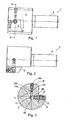
- Ein Ausführungsbeispiel der Erfindung ist in den Zeichnungen dargestellt und unter Angabe weiterer Vorteile und Einzelheiten nachstehend näher erläutert. Es zeigen
- Figur 1
- eine Seitenansicht eines Werkzeugs mit hydraulischer Schneidplatteneinstellung,
- Figur 2
- eine in Bezug auf
Figur 1 um 90° gedrehte Seitenansicht des Werkzeugs und - Figur 3
- eine Schnittansicht des Werkzeugs nach
Figur 1 bei einem Schnitt entlang der Schnittlinie A-A inFigur 1 . - In den Figuren ist ein Feinbearbeitungswerkzeug 1 abgebildet. Das Feinbearbeitungswerkzeug 1 umfasst einen Grundkörper 2 und einen daran einstückig angeordneten Tragarm 3. Zur Aufnahme des Werkzeugs in z.B. eine Spindel einer Werkzeugmaschine ist ein Schaft 4 vorgesehen.
- Am Tragarm 3 ist eine Schneidplatte 5 beispielhaft über eine Befestigungsschraube 6 angeordnet.
- Die Position des Tragarms 3 wird über ein Hydrauliksystems 7 vorgegeben, dass im Grundkörper 2 ausgebildet ist. Das Hydrauliksystem 7 umfasst einen Einstellkolben 8 der in einer Bohrung 8a verschiebbar geführt ist. An der zum Tragarm abgewandten Seite ist eine Dichtung 8b vorgesehen, um den Kolben 8 gegen die Wandung der Bohrung 8a zuverlässig abzudichten.
- Im Weiteren umfasst das Hydrauliksystem eine Justierschraube 9 in einer Gewindebohrung 9a im Grundkörper 2.
- Die Justierschraube 9 drückt auf ein Kolbenelement 10, das in einer der Gewindebohrung 9a nachgeordneten Bohrung 10a verschiebbar angeordnet ist.
- Auf der zur Justierschraube 9 entgegengesetzten Seite des Kolbenelements 10 ist eine Dichtung 10b vorgesehen, um das Kolbenelement 10 nach außen hin zur Justierschraube 9 zuverlässig abzudichten. Die Bohrung 8a und die Bohrung 10a schneiden sich und bilden mit den um den vom Einstellkolben 8 bzw. dessen Dichtung 8b und vom Kolben 10 bzw. dessen Dichtung 10b nicht eingenommenen Volumina der jeweiligen Bohrungen 8a bzw. 10a eine Fluidkammer 11 aus. Die Fluidkammer 11 ist vorzugsweise mit einem Hydrauliköl befüllt.
- Durch Verstellen der Justierschraube 9, insbesondere Eindrehen, wird das Kolbenelement 10 mitverschoben. Zum Volumenausgleich des dadurch verdrängten Hydraulikfluids wird der Einstellkolben 8 aus der Bohrung 8a hinausgeschoben und drückt auf den Tragarm 3.
- Ein Wiederlager am Tragarm 3 ist als die Schraube 12 ausgebildet. Die Schraube 12 weist beispielsweise einen Innensechskant auf, um eine Verstellung am Tragarm 3 vornehmen zu können. Damit kann z.B. eine Grobjustierung in Bezug auf die Einstellung des Hydrauliksystems 7 erfolgen.
- Die Justierschraube 9 kann vorteilhafterweise ebenfalls über einen Innensechskant betätig werden.
- In einer außerdem bevorzugten Ausgestaltung der Erfindung besitzt das Hydrauliksystem 7 eine fernbetätigte Bedienung.
- Z.B. ist das Hydrauliksystem 7 über eine Hydraulikleitung mit einem vom Werkzeug 1 separaten Steuersystem verbunden. Dies kann über eine separate Hydraulikleitung erfolgen.
- Die Hydraulikleitung ist beispielweise als zentraler Kanal im Feinbearbeitungswerkzeug 1 ausgebildet.
- Auf diese Weise kann die Versorgung des zentralen Kanals (nicht dargestellt) über eine Maschinespindel einer Werkzeugmaschine erfolgen. Dies ist insbesondere dann von Vorteil, wenn das Werkzeug 1 rotierend eingesetzt wird. Bei einer nicht rotierenden Anwendung ist es allerdings auch denkbar, eine Hydraulikleitung außerhalb der Werkzeugachse zuzuführen, gegebenenfalls auch auf der Außenseite des Werkzeugs.
-
- 1
- Feinbearbeitungswerkzeug
- 2
- Grundkörper
- 3
- Tragarm
- 4
- Schaft
- 5
- Schneidplatte
- 6
- Befestigungsschraube
- 7
- Hydrauliksystem
- 8
- Einstellkolben
- 8a
- Bohrung
- 8b
- Dichtung
- 9
- Justierschraube
- 9a
- Gewindebohrung
- 10
- Kolbenelement
- 10a
- Bohrung
- 10b
- Dichtung
- 11
- Fluidkammer
- 12
- Schraube
Claims (10)
- Spanabhebendes Werkzeug (1) mit einem Werkzeugträger, der ein Tragorgan (3) mit einer Schneidplatte (5) und einen Grundkörper (2) umfasst, wobei das Tragorgan (3) elastisch mit den Grundkörper (2) verbunden ist, sowie Justiermittel zur Positionierung des Tragorgans (3) mit Schneidplatte (5) am Grundkörper, wobei die Justiermittel ein hydraulisch und/oder pneumatisch betätigbares Einstellelement (8) aufweisen, dadurch gekennzeichnet, dass der Werkzeugträger mit Tragorgan (3) und Grundkörper (2) einstückig ausgebildet ist.
- Werkzeug nach Anspruch 1, dadurch gekennzeichnet, dass die Justiermittel eine mit Fluid gefüllte Fluidkammer (11) aufweisen.
- Werkzeug nach einem der vorhergehenden Ansprüche, dadurch gekennzeichnet, dass eine erste Öffnung der Fluidkammer (11) von einer Justierschraube (9) mit Dichtmittel (0b) verschlossen ist.
- Werkzeug nach einem der vorhergehenden Ansprüche, dadurch gekennzeichnet, dass eine zweite Öffnung der Fluidkammer (11) mit dem Einstellelement (8) verschlossen ist.
- Werkzeug nach einem der vorhergehenden Ansprüche, dadurch gekennzeichnet, dass das Einstellelement (8) unmittelbar auf das Tragorgan (3) wirkt.
- Werkzeug nach einem der vorhergehenden Ansprüche, dadurch gekennzeichnet, dass die Fluidkammer (11) im Grundkörper (2) ausgebildet ist.
- Werkzeug nach einem der vorhergehenden Ansprüche, dadurch gekennzeichnet, dass am Tragorgan (3) ein verstellbares Wiederlager (12) vorgesehen ist.
- Werkzeug nach einem der vorhergehenden Ansprüche, dadurch gekennzeichnet, dass die Fluidkammer (11) derart ausgebildet ist, dass das Einstellelement (8) und die Justierschraube (9) im Winkel zueinander stehen.
- Werkzeug nach einem der vorhergehenden Ansprüche, dadurch gekennzeichnet, dass das Einstellelement einen hydraulisch bewegbaren Kolben (8) umfasst.
- Werkzeug nach Anspruch 9, dadurch gekennzeichnet, dass der Kolben (8) mit Dichtmitteln (8b) versehen ist.
Applications Claiming Priority (2)
| Application Number | Priority Date | Filing Date | Title |
|---|---|---|---|
| DE102006057052 | 2006-11-30 | ||
| PCT/DE2007/002143 WO2008064657A2 (de) | 2006-11-30 | 2007-11-28 | Spanabhebendes werkzeug |
Publications (2)
| Publication Number | Publication Date |
|---|---|
| EP2107958A2 EP2107958A2 (de) | 2009-10-14 |
| EP2107958B1 true EP2107958B1 (de) | 2013-07-17 |
Family
ID=39462178
Family Applications (1)
| Application Number | Title | Priority Date | Filing Date |
|---|---|---|---|
| EP07856036.4A Active EP2107958B1 (de) | 2006-11-30 | 2007-11-28 | Spanabhebendes werkzeug |
Country Status (2)
| Country | Link |
|---|---|
| EP (1) | EP2107958B1 (de) |
| WO (1) | WO2008064657A2 (de) |
Families Citing this family (2)
| Publication number | Priority date | Publication date | Assignee | Title |
|---|---|---|---|---|
| DE102019215695B4 (de) * | 2019-10-11 | 2025-07-24 | Kennametal Inc. | Dichtkolben für eine hydraulische Werkzeughalterung und hydraulische Werkzeughalterung |
| CN113441770B (zh) * | 2020-03-27 | 2025-02-25 | 京瓷株式会社 | 刀柄及切削刀具 |
Family Cites Families (3)
| Publication number | Priority date | Publication date | Assignee | Title |
|---|---|---|---|---|
| CH463241A (de) * | 1967-01-23 | 1968-09-30 | Wolf Adolf | Fräswerkzeug mit einem Grundkörper und auswechselbaren Messern |
| DE10350851B4 (de) * | 2003-10-31 | 2008-11-20 | Leitz Gmbh & Co. Kg | Fräswerkzeug |
| DE102004017714B4 (de) * | 2003-12-10 | 2015-10-15 | GFE-Gesellschaft für Fertigungstechnik und Entwicklung Schmalkalden/Chemnitz mbH | Einstell- und Verstellsystem für leistenförmige Schneidenträger an spanend arbeitenden Werkzeugen |
-
2007
- 2007-11-28 EP EP07856036.4A patent/EP2107958B1/de active Active
- 2007-11-28 WO PCT/DE2007/002143 patent/WO2008064657A2/de not_active Ceased
Also Published As
| Publication number | Publication date |
|---|---|
| EP2107958A2 (de) | 2009-10-14 |
| WO2008064657A3 (de) | 2008-08-21 |
| WO2008064657A2 (de) | 2008-06-05 |
Similar Documents
| Publication | Publication Date | Title |
|---|---|---|
| EP1140400B1 (de) | Zerspanungs-werkzeug für die hochgeschwindigkeitsbearbeitung | |
| EP2370222B1 (de) | Werkzeugaufnahme | |
| DE3904259C2 (de) | ||
| EP2300183A1 (de) | Ausbohrwerkzeug | |
| EP2318165B1 (de) | Maschinenwerkzeug mit verstellbarer schneidplatte | |
| DE102005030820B3 (de) | Spannvorrichtung | |
| WO2018046036A2 (de) | Mehrschneidiges zerspanungswerkzeug und verfahren zum bearbeiten einer lagergasse | |
| WO2009033456A2 (de) | Vorrichtung zum halten von werkzeugen bei werkzeugmaschinen | |
| EP2758198B1 (de) | Werkzeugkassette und zerspanungswerkzeug mit einer werkzeugkassette | |
| DE19519639B4 (de) | Werkzeugkopf mit axial verstellbarem Spannfutter | |
| EP0486532B1 (de) | Werkzeug für den einsatz in werkzeugmaschinen | |
| EP3658318B1 (de) | Zerspanungswerkzeug mit einer justiereinrichtung | |
| EP3658321B1 (de) | Zerspanungswerkzeug | |
| EP1660262B1 (de) | Schnittstelle eines werkzeugs | |
| DE102014117247B3 (de) | Werkzeug zum Ausdrehen einer Bohrung | |
| EP2777848B1 (de) | Spann- oder Greifeinrichtung | |
| EP3658320B1 (de) | Zerspanungswerkzeug mit einer stelleinrichtung | |
| DE102007009610B4 (de) | Spanabhebendes Werkzeug | |
| WO2008064657A2 (de) | Spanabhebendes werkzeug | |
| EP2777849B1 (de) | Spann- oder Greifeinrichtung | |
| EP2777850B1 (de) | Spann- oder Greifeinrichtung | |
| DE202007004957U1 (de) | Stanzvorrichtung | |
| DE102006052051A1 (de) | Werkzeughalter | |
| DE10216538A1 (de) | Werkzeugkopf | |
| EP3670045B1 (de) | Hydrodehnspannfutter sowie bohrvorschubeinheit |
Legal Events
| Date | Code | Title | Description |
|---|---|---|---|
| PUAI | Public reference made under article 153(3) epc to a published international application that has entered the european phase |
Free format text: ORIGINAL CODE: 0009012 |
|
| 17P | Request for examination filed |
Effective date: 20090629 |
|
| AK | Designated contracting states |
Kind code of ref document: A2 Designated state(s): AT BE BG CH CY CZ DE DK EE ES FI FR GB GR HU IE IS IT LI LT LU LV MC MT NL PL PT RO SE SI SK TR |
|
| DAX | Request for extension of the european patent (deleted) | ||
| 17Q | First examination report despatched |
Effective date: 20101019 |
|
| GRAP | Despatch of communication of intention to grant a patent |
Free format text: ORIGINAL CODE: EPIDOSNIGR1 |
|
| GRAS | Grant fee paid |
Free format text: ORIGINAL CODE: EPIDOSNIGR3 |
|
| GRAA | (expected) grant |
Free format text: ORIGINAL CODE: 0009210 |
|
| AK | Designated contracting states |
Kind code of ref document: B1 Designated state(s): AT BE BG CH CY CZ DE DK EE ES FI FR GB GR HU IE IS IT LI LT LU LV MC MT NL PL PT RO SE SI SK TR |
|
| REG | Reference to a national code |
Ref country code: GB Ref legal event code: FG4D Free format text: NOT ENGLISH |
|
| REG | Reference to a national code |
Ref country code: CH Ref legal event code: EP |
|
| REG | Reference to a national code |
Ref country code: IE Ref legal event code: FG4D Free format text: LANGUAGE OF EP DOCUMENT: GERMAN |
|
| REG | Reference to a national code |
Ref country code: AT Ref legal event code: REF Ref document number: 621855 Country of ref document: AT Kind code of ref document: T Effective date: 20130815 |
|
| REG | Reference to a national code |
Ref country code: DE Ref legal event code: R096 Ref document number: 502007012061 Country of ref document: DE Effective date: 20130912 |
|
| REG | Reference to a national code |
Ref country code: NL Ref legal event code: VDEP Effective date: 20130717 |
|
| REG | Reference to a national code |
Ref country code: LT Ref legal event code: MG4D |
|
| PG25 | Lapsed in a contracting state [announced via postgrant information from national office to epo] |
Ref country code: PT Free format text: LAPSE BECAUSE OF FAILURE TO SUBMIT A TRANSLATION OF THE DESCRIPTION OR TO PAY THE FEE WITHIN THE PRESCRIBED TIME-LIMIT Effective date: 20131118 Ref country code: CY Free format text: LAPSE BECAUSE OF FAILURE TO SUBMIT A TRANSLATION OF THE DESCRIPTION OR TO PAY THE FEE WITHIN THE PRESCRIBED TIME-LIMIT Effective date: 20130807 Ref country code: IS Free format text: LAPSE BECAUSE OF FAILURE TO SUBMIT A TRANSLATION OF THE DESCRIPTION OR TO PAY THE FEE WITHIN THE PRESCRIBED TIME-LIMIT Effective date: 20131117 Ref country code: SE Free format text: LAPSE BECAUSE OF FAILURE TO SUBMIT A TRANSLATION OF THE DESCRIPTION OR TO PAY THE FEE WITHIN THE PRESCRIBED TIME-LIMIT Effective date: 20130717 Ref country code: LT Free format text: LAPSE BECAUSE OF FAILURE TO SUBMIT A TRANSLATION OF THE DESCRIPTION OR TO PAY THE FEE WITHIN THE PRESCRIBED TIME-LIMIT Effective date: 20130717 |
|
| REG | Reference to a national code |
Ref country code: DE Ref legal event code: R082 Ref document number: 502007012061 Country of ref document: DE Representative=s name: BODE MEITINGER PATENTANWALTSGESELLSCHAFT MBH, DE |
|
| PG25 | Lapsed in a contracting state [announced via postgrant information from national office to epo] |
Ref country code: PL Free format text: LAPSE BECAUSE OF FAILURE TO SUBMIT A TRANSLATION OF THE DESCRIPTION OR TO PAY THE FEE WITHIN THE PRESCRIBED TIME-LIMIT Effective date: 20130717 Ref country code: GR Free format text: LAPSE BECAUSE OF FAILURE TO SUBMIT A TRANSLATION OF THE DESCRIPTION OR TO PAY THE FEE WITHIN THE PRESCRIBED TIME-LIMIT Effective date: 20131018 Ref country code: SI Free format text: LAPSE BECAUSE OF FAILURE TO SUBMIT A TRANSLATION OF THE DESCRIPTION OR TO PAY THE FEE WITHIN THE PRESCRIBED TIME-LIMIT Effective date: 20130717 Ref country code: ES Free format text: LAPSE BECAUSE OF FAILURE TO SUBMIT A TRANSLATION OF THE DESCRIPTION OR TO PAY THE FEE WITHIN THE PRESCRIBED TIME-LIMIT Effective date: 20131028 Ref country code: LV Free format text: LAPSE BECAUSE OF FAILURE TO SUBMIT A TRANSLATION OF THE DESCRIPTION OR TO PAY THE FEE WITHIN THE PRESCRIBED TIME-LIMIT Effective date: 20130717 Ref country code: FI Free format text: LAPSE BECAUSE OF FAILURE TO SUBMIT A TRANSLATION OF THE DESCRIPTION OR TO PAY THE FEE WITHIN THE PRESCRIBED TIME-LIMIT Effective date: 20130717 Ref country code: NL Free format text: LAPSE BECAUSE OF FAILURE TO SUBMIT A TRANSLATION OF THE DESCRIPTION OR TO PAY THE FEE WITHIN THE PRESCRIBED TIME-LIMIT Effective date: 20130717 |
|
| REG | Reference to a national code |
Ref country code: DE Ref legal event code: R082 Ref document number: 502007012061 Country of ref document: DE Representative=s name: BODE MEITINGER PATENTANWALTSGESELLSCHAFT MBH, DE Effective date: 20140203 Ref country code: DE Ref legal event code: R081 Ref document number: 502007012061 Country of ref document: DE Owner name: GUEHRING KG, DE Free format text: FORMER OWNER: GUEHRING OHG, 72458 ALBSTADT, DE Effective date: 20140203 |
|
| PG25 | Lapsed in a contracting state [announced via postgrant information from national office to epo] |
Ref country code: CY Free format text: LAPSE BECAUSE OF FAILURE TO SUBMIT A TRANSLATION OF THE DESCRIPTION OR TO PAY THE FEE WITHIN THE PRESCRIBED TIME-LIMIT Effective date: 20130717 |
|
| PG25 | Lapsed in a contracting state [announced via postgrant information from national office to epo] |
Ref country code: CZ Free format text: LAPSE BECAUSE OF FAILURE TO SUBMIT A TRANSLATION OF THE DESCRIPTION OR TO PAY THE FEE WITHIN THE PRESCRIBED TIME-LIMIT Effective date: 20130717 Ref country code: RO Free format text: LAPSE BECAUSE OF FAILURE TO SUBMIT A TRANSLATION OF THE DESCRIPTION OR TO PAY THE FEE WITHIN THE PRESCRIBED TIME-LIMIT Effective date: 20130717 Ref country code: DK Free format text: LAPSE BECAUSE OF FAILURE TO SUBMIT A TRANSLATION OF THE DESCRIPTION OR TO PAY THE FEE WITHIN THE PRESCRIBED TIME-LIMIT Effective date: 20130717 Ref country code: EE Free format text: LAPSE BECAUSE OF FAILURE TO SUBMIT A TRANSLATION OF THE DESCRIPTION OR TO PAY THE FEE WITHIN THE PRESCRIBED TIME-LIMIT Effective date: 20130717 Ref country code: SK Free format text: LAPSE BECAUSE OF FAILURE TO SUBMIT A TRANSLATION OF THE DESCRIPTION OR TO PAY THE FEE WITHIN THE PRESCRIBED TIME-LIMIT Effective date: 20130717 |
|
| PLBE | No opposition filed within time limit |
Free format text: ORIGINAL CODE: 0009261 |
|
| STAA | Information on the status of an ep patent application or granted ep patent |
Free format text: STATUS: NO OPPOSITION FILED WITHIN TIME LIMIT |
|
| PG25 | Lapsed in a contracting state [announced via postgrant information from national office to epo] |
Ref country code: IT Free format text: LAPSE BECAUSE OF FAILURE TO SUBMIT A TRANSLATION OF THE DESCRIPTION OR TO PAY THE FEE WITHIN THE PRESCRIBED TIME-LIMIT Effective date: 20130717 |
|
| BERE | Be: lapsed |
Owner name: GUHRING OHG Effective date: 20131130 |
|
| 26N | No opposition filed |
Effective date: 20140422 |
|
| REG | Reference to a national code |
Ref country code: CH Ref legal event code: PL |
|
| GBPC | Gb: european patent ceased through non-payment of renewal fee |
Effective date: 20131128 |
|
| PG25 | Lapsed in a contracting state [announced via postgrant information from national office to epo] |
Ref country code: LI Free format text: LAPSE BECAUSE OF NON-PAYMENT OF DUE FEES Effective date: 20131130 Ref country code: CH Free format text: LAPSE BECAUSE OF NON-PAYMENT OF DUE FEES Effective date: 20131130 Ref country code: MC Free format text: LAPSE BECAUSE OF FAILURE TO SUBMIT A TRANSLATION OF THE DESCRIPTION OR TO PAY THE FEE WITHIN THE PRESCRIBED TIME-LIMIT Effective date: 20130717 |
|
| REG | Reference to a national code |
Ref country code: DE Ref legal event code: R097 Ref document number: 502007012061 Country of ref document: DE Effective date: 20140422 |
|
| REG | Reference to a national code |
Ref country code: FR Ref legal event code: ST Effective date: 20140731 |
|
| REG | Reference to a national code |
Ref country code: IE Ref legal event code: MM4A |
|
| PG25 | Lapsed in a contracting state [announced via postgrant information from national office to epo] |
Ref country code: BE Free format text: LAPSE BECAUSE OF NON-PAYMENT OF DUE FEES Effective date: 20131130 |
|
| PG25 | Lapsed in a contracting state [announced via postgrant information from national office to epo] |
Ref country code: IE Free format text: LAPSE BECAUSE OF NON-PAYMENT OF DUE FEES Effective date: 20131128 |
|
| PG25 | Lapsed in a contracting state [announced via postgrant information from national office to epo] |
Ref country code: FR Free format text: LAPSE BECAUSE OF NON-PAYMENT OF DUE FEES Effective date: 20131202 Ref country code: GB Free format text: LAPSE BECAUSE OF NON-PAYMENT OF DUE FEES Effective date: 20131128 |
|
| REG | Reference to a national code |
Ref country code: AT Ref legal event code: MM01 Ref document number: 621855 Country of ref document: AT Kind code of ref document: T Effective date: 20131128 |
|
| PG25 | Lapsed in a contracting state [announced via postgrant information from national office to epo] |
Ref country code: AT Free format text: LAPSE BECAUSE OF NON-PAYMENT OF DUE FEES Effective date: 20131128 |
|
| PG25 | Lapsed in a contracting state [announced via postgrant information from national office to epo] |
Ref country code: TR Free format text: LAPSE BECAUSE OF FAILURE TO SUBMIT A TRANSLATION OF THE DESCRIPTION OR TO PAY THE FEE WITHIN THE PRESCRIBED TIME-LIMIT Effective date: 20130717 |
|
| PG25 | Lapsed in a contracting state [announced via postgrant information from national office to epo] |
Ref country code: HU Free format text: LAPSE BECAUSE OF FAILURE TO SUBMIT A TRANSLATION OF THE DESCRIPTION OR TO PAY THE FEE WITHIN THE PRESCRIBED TIME-LIMIT; INVALID AB INITIO Effective date: 20071128 Ref country code: BG Free format text: LAPSE BECAUSE OF FAILURE TO SUBMIT A TRANSLATION OF THE DESCRIPTION OR TO PAY THE FEE WITHIN THE PRESCRIBED TIME-LIMIT Effective date: 20130717 Ref country code: LU Free format text: LAPSE BECAUSE OF NON-PAYMENT OF DUE FEES Effective date: 20131128 |
|
| PG25 | Lapsed in a contracting state [announced via postgrant information from national office to epo] |
Ref country code: MT Free format text: LAPSE BECAUSE OF FAILURE TO SUBMIT A TRANSLATION OF THE DESCRIPTION OR TO PAY THE FEE WITHIN THE PRESCRIBED TIME-LIMIT Effective date: 20130717 |
|
| REG | Reference to a national code |
Ref country code: DE Ref legal event code: R082 Ref document number: 502007012061 Country of ref document: DE Representative=s name: MEITINGER PATENTANWALTS GMBH, DE |
|
| PGFP | Annual fee paid to national office [announced via postgrant information from national office to epo] |
Ref country code: DE Payment date: 20251130 Year of fee payment: 19 |