EP2107561A1 - Datenseite für ein holografisches Datenspeichersystem - Google Patents
Datenseite für ein holografisches Datenspeichersystem Download PDFInfo
- Publication number
- EP2107561A1 EP2107561A1 EP08154080A EP08154080A EP2107561A1 EP 2107561 A1 EP2107561 A1 EP 2107561A1 EP 08154080 A EP08154080 A EP 08154080A EP 08154080 A EP08154080 A EP 08154080A EP 2107561 A1 EP2107561 A1 EP 2107561A1
- Authority
- EP
- European Patent Office
- Prior art keywords
- data page
- phase
- data
- phase mask
- blocks
- Prior art date
- Legal status (The legal status is an assumption and is not a legal conclusion. Google has not performed a legal analysis and makes no representation as to the accuracy of the status listed.)
- Withdrawn
Links
- 238000013500 data storage Methods 0.000 title claims abstract description 11
- 238000000034 method Methods 0.000 claims abstract description 4
- 230000010363 phase shift Effects 0.000 description 8
- 230000001629 suppression Effects 0.000 description 5
- 238000001514 detection method Methods 0.000 description 3
- 230000007704 transition Effects 0.000 description 3
- 230000000694 effects Effects 0.000 description 2
- 230000001427 coherent effect Effects 0.000 description 1
- 238000003384 imaging method Methods 0.000 description 1
- 239000011159 matrix material Substances 0.000 description 1
- 238000012986 modification Methods 0.000 description 1
- 230000004048 modification Effects 0.000 description 1
- 230000003287 optical effect Effects 0.000 description 1
- 238000001228 spectrum Methods 0.000 description 1
- 239000011232 storage material Substances 0.000 description 1
Images


Classifications
-
- G—PHYSICS
- G03—PHOTOGRAPHY; CINEMATOGRAPHY; ANALOGOUS TECHNIQUES USING WAVES OTHER THAN OPTICAL WAVES; ELECTROGRAPHY; HOLOGRAPHY
- G03H—HOLOGRAPHIC PROCESSES OR APPARATUS
- G03H1/00—Holographic processes or apparatus using light, infrared or ultraviolet waves for obtaining holograms or for obtaining an image from them; Details peculiar thereto
- G03H1/04—Processes or apparatus for producing holograms
-
- G—PHYSICS
- G11—INFORMATION STORAGE
- G11B—INFORMATION STORAGE BASED ON RELATIVE MOVEMENT BETWEEN RECORD CARRIER AND TRANSDUCER
- G11B7/00—Recording or reproducing by optical means, e.g. recording using a thermal beam of optical radiation by modifying optical properties or the physical structure, reproducing using an optical beam at lower power by sensing optical properties; Record carriers therefor
- G11B7/007—Arrangement of the information on the record carrier, e.g. form of tracks, actual track shape, e.g. wobbled, or cross-section, e.g. v-shaped; Sequential information structures, e.g. sectoring or header formats within a track
- G11B7/00772—Arrangement of the information on the record carrier, e.g. form of tracks, actual track shape, e.g. wobbled, or cross-section, e.g. v-shaped; Sequential information structures, e.g. sectoring or header formats within a track on record carriers storing information in the form of optical interference patterns, e.g. holograms
-
- G—PHYSICS
- G11—INFORMATION STORAGE
- G11B—INFORMATION STORAGE BASED ON RELATIVE MOVEMENT BETWEEN RECORD CARRIER AND TRANSDUCER
- G11B7/00—Recording or reproducing by optical means, e.g. recording using a thermal beam of optical radiation by modifying optical properties or the physical structure, reproducing using an optical beam at lower power by sensing optical properties; Record carriers therefor
- G11B7/12—Heads, e.g. forming of the optical beam spot or modulation of the optical beam
- G11B7/125—Optical beam sources therefor, e.g. laser control circuitry specially adapted for optical storage devices; Modulators, e.g. means for controlling the size or intensity of optical spots or optical traces
- G11B7/128—Modulators
-
- G—PHYSICS
- G03—PHOTOGRAPHY; CINEMATOGRAPHY; ANALOGOUS TECHNIQUES USING WAVES OTHER THAN OPTICAL WAVES; ELECTROGRAPHY; HOLOGRAPHY
- G03H—HOLOGRAPHIC PROCESSES OR APPARATUS
- G03H1/00—Holographic processes or apparatus using light, infrared or ultraviolet waves for obtaining holograms or for obtaining an image from them; Details peculiar thereto
- G03H1/04—Processes or apparatus for producing holograms
- G03H1/0402—Recording geometries or arrangements
- G03H2001/0415—Recording geometries or arrangements for recording reflection holograms
- G03H2001/0417—Recording geometries or arrangements for recording reflection holograms for recording single beam Lippmann hologram wherein the object is illuminated by reference beam passing through the recording material
-
- G—PHYSICS
- G03—PHOTOGRAPHY; CINEMATOGRAPHY; ANALOGOUS TECHNIQUES USING WAVES OTHER THAN OPTICAL WAVES; ELECTROGRAPHY; HOLOGRAPHY
- G03H—HOLOGRAPHIC PROCESSES OR APPARATUS
- G03H2210/00—Object characteristics
- G03H2210/20—2D object
- G03H2210/22—2D SLM object wherein the object beam is formed of the light modulated by the SLM
-
- G—PHYSICS
- G03—PHOTOGRAPHY; CINEMATOGRAPHY; ANALOGOUS TECHNIQUES USING WAVES OTHER THAN OPTICAL WAVES; ELECTROGRAPHY; HOLOGRAPHY
- G03H—HOLOGRAPHIC PROCESSES OR APPARATUS
- G03H2223/00—Optical components
- G03H2223/13—Phase mask
-
- G—PHYSICS
- G03—PHOTOGRAPHY; CINEMATOGRAPHY; ANALOGOUS TECHNIQUES USING WAVES OTHER THAN OPTICAL WAVES; ELECTROGRAPHY; HOLOGRAPHY
- G03H—HOLOGRAPHIC PROCESSES OR APPARATUS
- G03H2225/00—Active addressable light modulator
- G03H2225/55—Having optical element registered to each pixel
Definitions
- the present invention relates to a data page for use in a holographic data storage system, and to a method and an apparatus for writing to holographic storage media using such a data page.
- holographic data storage digital data are stored by recording the interference pattern produced by the superposition of two coherent laser beams, where one beam, the so-called 'object beam', is modulated by a spatial light modulator (SLM) and carries the information to be recorded.
- the second beam serves as a reference beam.
- the interference pattern leads to modifications of specific properties of the storage material, which depend on the local intensity of the interference pattern. Reading of a recorded hologram is performed by illuminating the hologram with the reference beam using the same conditions as during recording. This results in the reconstruction of the recorded object beam.
- holographic data storage is an increased data capacity. Contrary to conventional optical storage media, the volume of the holographic storage medium is used for storing information, not just a few layers.
- One further advantage of holographic data storage is the possibility to store multiple data in the same volume, e.g. by changing the angle between the two beams or by using shift multiplexing, etc.
- data are stored as data pages.
- a data page consists of a matrix of light-dark-patterns, i.e. a two dimensional binary array or an array of grey values, which code multiple bits. This allows to achieve increased data rates in addition to the increased storage density.
- the data page is imprinted onto the object beam by the spatial light modulator and detected with an array detector.
- a pixelated spatial light modulator is used for modulating the object beam intensity with information.
- This intensity distribution is usually Fourier transformed by an objective lens.
- the Fourier transform i.e. the spectrum of a pixelated data pattern, has a high central intensity peak, hereafter referred to as DC peak.
- the actual information is distributed around this peak on a much lower level, typically -60dB.
- the DC peak of the object beam can cause an undesired saturation of the photosensitive medium.
- the envelope of the surrounding intensity distribution can be described by a 2-dimensional sinc-function (sin(x)/x ), which results from the usual square-like shape of the pixels.
- the full information about the SLM pixel pattern is located below the so-called Nyquist limit which lies at half the distance to the first zero of the sinc-function.
- phase masks need to be aligned to better than ⁇ 10% of the pixel width of the SLM.
- the pixel width is typical 10 ⁇ m, so that the alignment tolerances are only ⁇ 1 ⁇ m in the x- and y-direction perpendicular to the object beam.
- Misalignment of the phase mask with respect to the data page pixels leads to disturbances in the recorded data page.
- the disturbances are caused by the transition zones between those areas of the phase mask with different phase, i.e. by phase jumps of the phase mask.
- the disturbances in the recorded data page decrease the reliability of the data detection and, therefore, increase the error rate.
- this object is achieved by a data page for use in a holographic data storage system with a phase mask having a plurality of phase blocks, wherein the data page has dark zones consisting of switched-off pixels, the dark zones coinciding with boundaries between the phase blocks of the phase mask.
- the data page has dark zones consisting of switched-off pixels, which coincide with boundaries between the phase blocks of the phase mask.
- a method for writing to holographic storage media in a holographic storage system includes the steps of imprinting a data page onto an object beam with a spatial light modulator, the data page having dark zones consisting of switched-off pixels, wherein the dark zones are chosen such that they coincide with boundaries between phase blocks of a phase mask of the holographic storage system.
- the alignment tolerances for the phase mask are significantly increased. No additional components are necessary for this purpose, which allows for an easy and cheap implementation of the invention.
- the dark zones slightly reduce the data capacity per data page, this reduction can be reduced to a minimum by using the dark lines as sync marks for data detection.
- the data page has data areas with a fixed block size or a variable block size.
- the choice between a fixed block size or a variable block size allows to implement different data coding schemes.
- the phase mask is a binary phase mask or a grey level phase mask.
- the choice of a specific type of phase mask depends, inter alia, on the type of holographic storage system and the desired suppression of the DC peak.
- Fig. 1 schematically depicts a known reflection type collinear holographic storage system 1.
- a laser beam 2 emitted by laser 3 and collimated by a lens 4 is deviated by a non-polarizing beam splitter 5 towards an objective lens 8, which focuses the beam into a holographic storage medium 9.
- the holographic storage medium has two cover layers 91, 9b and a hologram layer 9c.
- a transmitted beam 10 is collimated by a further objective lens 11 and sent through a binary phase plate 13 onto a reflective spatial light modulator (SLM) 14.
- the pixels of the SLM 14 can be switched between a reflective state and a transmissive or absorptive state.
- the SLM 14 reflects part 15 of the incident light beam 10 back towards the holographic storage medium 9.
- the binary phase plate 13 is pixel matched with the SLM 14 and reduces the Fourier peak of the reflected beam 15.
- the light beam 2 that goes from the non-polarizing beam splitter 5 towards the holographic storage medium 9 is the reference beam, whereas the light beam 15 reflected by the reflective SLM 14 towards the holographic storage medium 9 is the object beam.
- the reflective SLM 14 is used to imprint the data onto the wave front of the object beam 15.
- the two beams 2, 15 interfere within the holographic storage medium 9 and create a hologram.
- the reflective SLM 14 is switched in such a way that no light coming from laser 3 is reflected towards the holographic storage medium 9.
- the holographic storage medium 9 is illuminated by the light beam 2 emitted by the laser 3 via the objective lens 8.
- the hologram recorded in the holographic storage medium 9 reflects part 17 of the incident light beam 2, the reconstructed object beam 17, which corresponds to the stored data page.
- the reconstructed object beam 17 passes through the non-polarizing beam splitter 5.
- a Fourier filter 19 is introduced between two lenses 18 and 20 forming a 4f imaging system. The Fourier filter 19 allows to cancel high-frequency components generated by the binary phase plate 13. This is especially useful if the binary phase plate 13 is a phase plate consisting of individual pixels.
- a data page 30 according to the invention is depicted in Fig. 2 .
- the data page 30 consists of data areas 31 and a pattern of dark zones 32, where the object beam is always switched off and the data page 30 is dark.
- the dark zones 32 are lines with a width of one pixel. Of course, the lines can likewise have a width of more then one pixel.
- the dark zones 32 of the data page 30 are adapted to the phase pattern of the phase mask 13, as will be explained in the following with reference to Figs. 3 and 4 .
- Fig. 3 shows the phase mask 13 to which the data page of Fig. 2 is adapted.
- a binary phase plate 13 is used.
- the phase mask 13 has phase blocks 33, 34 with a constant phase.
- the dark grey phase blocks 33 denote a phase shift of ⁇
- the white phase blocks 34 denote a phase shift of 0.
- Fig. 4 The superposition of the data page of Fig.2 and the phase mask of Fig.3 is illustrated in Fig. 4 .
- the transition zones between the phase blocks 33, 34 of the phase mask 13, where the phase shift changes from ⁇ to 0 coincides with the center of the dark zones 32 of the data page 30.
- the alignment tolerances are relaxed by an additional term of ⁇ 0.5 times the width of a pixel, or even more when the width of the lines of the dark zones 32 is more than one pixel.
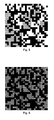
- Figs. 5 and 6 demonstrate the effects of a misalignment of the phase mask 13 with respect to the data page pixels in case of a conventional data page.
- Fig. 5 shows the superposition of the data page 30 and the phase mask 13.
- the pattern of small black and white pixels is the data page 30 generated by the SLM 14.
- the pattern of large grey and white blocks is the phase pattern generated by the phase mask.
- the phase mask 13 introduces a constant phase shift of ⁇ or 0 in phase blocks with a size of 5x5 pixels.
- the phase mask is misaligned by 0.5 pixels with respect to the data pixels.
- Fig. 6 depicts the appearance of the retrieved data page on the detector 21. As can be seen dark lines crossing the data blocks are produced by the transition zones between the phase blocks. These lines decrease the reliability of the data detection and cause an increased the error rate.
- Figs. 7 and 8 demonstrate the effects of a misalignment of the phase mask 13 with respect to the data page pixels in case of a data page 30 according to the invention.
- Fig. 7 shows the superposition of the data page 30 and the phase mask 13.
- the same phase mask with the same misalignment as in Figs. 5 and 6 is used.
- the data page 30 consists of 4x4 pixel blocks separated by a gap of one pixel.
- Fig. 8 depicts the appearance of the retrieved data page on the detector 21. Moreover, with a data page 30 according to the invention the data blocks are imaged without any disturbance by the phase shifts.
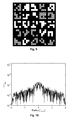
- the exemplary data page 30 depicted in Fig. 9 consists of 4x4 pixel blocks separated by a gap of one pixel.
- the phase mask 13 introduces a constant phase shift of ⁇ or 0 in phase blocks with a size of 5x5 pixels.
- the phase mask is correctly aligned with respect to the data pixels.
- Fig. 10 depicts a cut through the simulated intensity distribution of the resulting Fourier hologram. As can be seen the typical DC peak of Fourier holograms does not appear. For an optimum suppression of the DC peak the number of phase blocks 33 with a phase shift of ⁇ should be approximately the same as the number of phase blocks 34 with a phase shift of 0.
- Figs. 11 and 12 For comparison the case of a conventional data page without any phase plate is illustrated in Figs. 11 and 12.
- Fig. 11 depicts the data page
- Fig. 12 the cut through the simulated intensity distribution of the resulting Fourier hologram.
- the DC peak is present and exceeds the level of those components carrying information by orders of magnitude.
- FIGs. 13 to 16 different examples of data pages 30 according to the invention are illustrated.
- the superposition of the data page 30 and the phase mask 13 are shown.
- Fig. 13 depicts a data page with 4x4 pixel blocks separated by a gap of one pixel.
- Fig. 14 shows a data page with 8x8 pixel blocks separated by a gap of one pixel.
- a data page with pixel blocks of a variable block size separated by a gap of one pixel is illustrated in Fig. 15 .
- Fig. 16 shows a data page with pixel blocks of a variable block size separated by a gap of two pixels.
Landscapes
- Physics & Mathematics (AREA)
- Optics & Photonics (AREA)
- General Physics & Mathematics (AREA)
- Holo Graphy (AREA)
- Optical Recording Or Reproduction (AREA)
Priority Applications (5)
| Application Number | Priority Date | Filing Date | Title |
|---|---|---|---|
| EP08154080A EP2107561A1 (de) | 2008-04-04 | 2008-04-04 | Datenseite für ein holografisches Datenspeichersystem |
| US12/736,245 US8179767B2 (en) | 2008-04-04 | 2009-03-16 | Data page for use in a holographic data storage system |
| PCT/EP2009/053037 WO2009121709A1 (en) | 2008-04-04 | 2009-03-16 | Data page for use in a holographic data storage system |
| EP09729073A EP2260488B1 (de) | 2008-04-04 | 2009-03-16 | Verfahren zur speicherung auf ein holografisches datenspeichermedium |
| AT09729073T ATE521964T1 (de) | 2008-04-04 | 2009-03-16 | Verfahren zur speicherung auf ein holografisches datenspeichermedium |
Applications Claiming Priority (1)
| Application Number | Priority Date | Filing Date | Title |
|---|---|---|---|
| EP08154080A EP2107561A1 (de) | 2008-04-04 | 2008-04-04 | Datenseite für ein holografisches Datenspeichersystem |
Publications (1)
| Publication Number | Publication Date |
|---|---|
| EP2107561A1 true EP2107561A1 (de) | 2009-10-07 |
Family
ID=39671372
Family Applications (2)
| Application Number | Title | Priority Date | Filing Date |
|---|---|---|---|
| EP08154080A Withdrawn EP2107561A1 (de) | 2008-04-04 | 2008-04-04 | Datenseite für ein holografisches Datenspeichersystem |
| EP09729073A Not-in-force EP2260488B1 (de) | 2008-04-04 | 2009-03-16 | Verfahren zur speicherung auf ein holografisches datenspeichermedium |
Family Applications After (1)
| Application Number | Title | Priority Date | Filing Date |
|---|---|---|---|
| EP09729073A Not-in-force EP2260488B1 (de) | 2008-04-04 | 2009-03-16 | Verfahren zur speicherung auf ein holografisches datenspeichermedium |
Country Status (4)
| Country | Link |
|---|---|
| US (1) | US8179767B2 (de) |
| EP (2) | EP2107561A1 (de) |
| AT (1) | ATE521964T1 (de) |
| WO (1) | WO2009121709A1 (de) |
Families Citing this family (6)
| Publication number | Priority date | Publication date | Assignee | Title |
|---|---|---|---|---|
| JP5501217B2 (ja) * | 2010-12-27 | 2014-05-21 | 日立コンシューマエレクトロニクス株式会社 | 光情報再生装置及び光情報再生方法 |
| JP6143052B2 (ja) * | 2012-10-22 | 2017-06-07 | 国立研究開発法人産業技術総合研究所 | フーリエ変換ホログラム用ランダム位相マスク |
| US9823623B2 (en) | 2014-03-27 | 2017-11-21 | City University Of Hong Kong | Conversion of complex holograms to phase holograms |
| US9773128B2 (en) * | 2014-10-16 | 2017-09-26 | City University Of Hong Kong | Holographic encryption of multi-dimensional images |
| US9798290B2 (en) | 2015-09-25 | 2017-10-24 | City University Of Hong Kong | Holographic encryption of multi-dimensional images and decryption of encrypted multi-dimensional images |
| DE102020210935B3 (de) | 2020-08-31 | 2021-09-30 | Tesa Scribos Gmbh | Auslesevorrichtung zum Auslesen holographisch abgelegter Informationen, Verfahren zum Auslesen holographisch abgelegter Informationen |
Citations (4)
| Publication number | Priority date | Publication date | Assignee | Title |
|---|---|---|---|---|
| US4037918A (en) * | 1974-08-03 | 1977-07-26 | Matsushita Electric Industrial Co., Ltd. | Fourier-transform holography by pseudo-random phase shifting |
| US6281993B1 (en) * | 1998-03-30 | 2001-08-28 | International Business Machines Corporation | Phase shifting element for optical information processing storing systems |
| EP1324322A1 (de) * | 2000-08-07 | 2003-07-02 | Optware Corporation | Optisches informationsaufzeichnungsgerät und -verfahren, optisches informationswiedergabegerät und -verfahren und optisches informationsaufzeichnugns-/wiedergabegerät und -verfahren |
| US7130092B1 (en) * | 1998-02-27 | 2006-10-31 | Optware Corporation | Apparatus and method for recording and reproducing optical information |
Family Cites Families (5)
| Publication number | Priority date | Publication date | Assignee | Title |
|---|---|---|---|---|
| JP4295636B2 (ja) * | 2004-02-13 | 2009-07-15 | パイオニア株式会社 | ホログラム記録方法 |
| DE602005017257D1 (de) * | 2004-03-30 | 2009-12-03 | Pioneer Corp | 2-dimensionales modulationsverfahren zum aufzeichnen eines hologramms und hologrammeinrichtung |
| EP1873765A1 (de) * | 2006-06-27 | 2008-01-02 | Deutsche Thomson-Brandt Gmbh | Holographisches Speichersystem basierend auf Common-path-Interferometrie |
| US20100061213A1 (en) * | 2006-09-29 | 2010-03-11 | Koninklijke Philips Electronics N.V. | Optical holographic device and method with gain compensation |
| EP1970906A1 (de) * | 2007-03-15 | 2008-09-17 | Deutsche Thomson OHG | Verfahren und Speichermedium zum Kalibrieren eines holographischen Speichersystems |
-
2008
- 2008-04-04 EP EP08154080A patent/EP2107561A1/de not_active Withdrawn
-
2009
- 2009-03-16 EP EP09729073A patent/EP2260488B1/de not_active Not-in-force
- 2009-03-16 US US12/736,245 patent/US8179767B2/en not_active Expired - Fee Related
- 2009-03-16 WO PCT/EP2009/053037 patent/WO2009121709A1/en active Application Filing
- 2009-03-16 AT AT09729073T patent/ATE521964T1/de not_active IP Right Cessation
Patent Citations (4)
| Publication number | Priority date | Publication date | Assignee | Title |
|---|---|---|---|---|
| US4037918A (en) * | 1974-08-03 | 1977-07-26 | Matsushita Electric Industrial Co., Ltd. | Fourier-transform holography by pseudo-random phase shifting |
| US7130092B1 (en) * | 1998-02-27 | 2006-10-31 | Optware Corporation | Apparatus and method for recording and reproducing optical information |
| US6281993B1 (en) * | 1998-03-30 | 2001-08-28 | International Business Machines Corporation | Phase shifting element for optical information processing storing systems |
| EP1324322A1 (de) * | 2000-08-07 | 2003-07-02 | Optware Corporation | Optisches informationsaufzeichnungsgerät und -verfahren, optisches informationswiedergabegerät und -verfahren und optisches informationsaufzeichnugns-/wiedergabegerät und -verfahren |
Non-Patent Citations (1)
| Title |
|---|
| TANAKA ET AL.: "Improved performance in coaxial holographic data recording", OPT. EXPR, vol. 15, 2007, pages 16196 - 16209 |
Also Published As
| Publication number | Publication date |
|---|---|
| EP2260488A1 (de) | 2010-12-15 |
| EP2260488B1 (de) | 2011-08-24 |
| ATE521964T1 (de) | 2011-09-15 |
| US20110007620A1 (en) | 2011-01-13 |
| WO2009121709A1 (en) | 2009-10-08 |
| US8179767B2 (en) | 2012-05-15 |
Similar Documents
| Publication | Publication Date | Title |
|---|---|---|
| EP2028655B1 (de) | Vorrichtung und Verfahren zur holographischen Datenspeicherung mit einer Phasenmaske | |
| CN100568353C (zh) | 全息光信息记录再生装置以及全息光信息记录再生方法 | |
| EP2674944B1 (de) | Vorrichtung zur Aufzeichnung optischer Informationen, Verfahren zur Aufzeichnung optischer Informationen, Vorrichtung zur Wiedergabe optischer Informationen und Verfahren zur Wiedergabe optischer Informationen | |
| EP2260488B1 (de) | Verfahren zur speicherung auf ein holografisches datenspeichermedium | |
| JP3535776B2 (ja) | 2次元符号化方法 | |
| KR20060045492A (ko) | 인라인 방식 스펙클 다중 홀로그램 기록 장치 및 인라인방식 스펙클 다중 홀로그램 기록 방법 | |
| CN101826340A (zh) | 再现装置及再现方法 | |
| TWI417882B (zh) | 全像儲存系統及全像資料儲存方法 | |
| KR20090041332A (ko) | 잡음이 감소한 공통 개구의 홀로그래픽 저장 시스템 | |
| EP1983514B1 (de) | Vorrichtung zum Lesen von und/oder Schreiben auf holografischen Speichermedien | |
| JP2008130137A (ja) | 情報記録装置および情報再生装置 | |
| JP2008123657A (ja) | アポダイゼーション・フィルタを有するホログラフィック・ストレージ・システム | |
| EP2267703A1 (de) | Phasenmaske für ein Holographiespeichersystem | |
| JP2009259386A (ja) | 低雑音化ホログラム記憶システム | |
| JP2010238305A (ja) | 情報記録装置および情報記録方法 | |
| EP1837871B1 (de) | Holografisches Speichersystem und Verfahren dafür | |
| EP1933311B1 (de) | Vorbelichtung und Härtung eines lichtempfindlichen Materials zur Speicherung optischer Daten | |
| US8208184B2 (en) | Holographic storage system with improved data page quality | |
| EP1873766B1 (de) | Auf Interferometrie mit einem gemeinsamen Pfad basierendes holographisches Speichersystem | |
| Kim et al. | Digital hologram reconstruction using the dual-wavelength method | |
| Przygodda et al. | Special phase mask and related data format for page-based holographic data storage systems |
Legal Events
| Date | Code | Title | Description |
|---|---|---|---|
| PUAI | Public reference made under article 153(3) epc to a published international application that has entered the european phase |
Free format text: ORIGINAL CODE: 0009012 |
|
| AK | Designated contracting states |
Kind code of ref document: A1 Designated state(s): AT BE BG CH CY CZ DE DK EE ES FI FR GB GR HR HU IE IS IT LI LT LU LV MC MT NL NO PL PT RO SE SI SK TR |
|
| AX | Request for extension of the european patent |
Extension state: AL BA MK RS |
|
| AKX | Designation fees paid | ||
| STAA | Information on the status of an ep patent application or granted ep patent |
Free format text: STATUS: THE APPLICATION IS DEEMED TO BE WITHDRAWN |
|
| 18D | Application deemed to be withdrawn |
Effective date: 20100408 |
|
| REG | Reference to a national code |
Ref country code: DE Ref legal event code: 8566 |