EP2107347A1 - Flow detector with a housing - Google Patents
Flow detector with a housing Download PDFInfo
- Publication number
- EP2107347A1 EP2107347A1 EP08006853A EP08006853A EP2107347A1 EP 2107347 A1 EP2107347 A1 EP 2107347A1 EP 08006853 A EP08006853 A EP 08006853A EP 08006853 A EP08006853 A EP 08006853A EP 2107347 A1 EP2107347 A1 EP 2107347A1
- Authority
- EP
- European Patent Office
- Prior art keywords
- housing
- flow detector
- flow
- plate
- tongues
- Prior art date
- Legal status (The legal status is an assumption and is not a legal conclusion. Google has not performed a legal analysis and makes no representation as to the accuracy of the status listed.)
- Granted
Links
Images

Classifications
-
- G—PHYSICS
- G01—MEASURING; TESTING
- G01F—MEASURING VOLUME, VOLUME FLOW, MASS FLOW OR LIQUID LEVEL; METERING BY VOLUME
- G01F1/00—Measuring the volume flow or mass flow of fluid or fluent solid material wherein the fluid passes through a meter in a continuous flow
- G01F1/68—Measuring the volume flow or mass flow of fluid or fluent solid material wherein the fluid passes through a meter in a continuous flow by using thermal effects
- G01F1/684—Structural arrangements; Mounting of elements, e.g. in relation to fluid flow
- G01F1/6842—Structural arrangements; Mounting of elements, e.g. in relation to fluid flow with means for influencing the fluid flow
-
- G—PHYSICS
- G01—MEASURING; TESTING
- G01F—MEASURING VOLUME, VOLUME FLOW, MASS FLOW OR LIQUID LEVEL; METERING BY VOLUME
- G01F1/00—Measuring the volume flow or mass flow of fluid or fluent solid material wherein the fluid passes through a meter in a continuous flow
- G01F1/68—Measuring the volume flow or mass flow of fluid or fluent solid material wherein the fluid passes through a meter in a continuous flow by using thermal effects
- G01F1/684—Structural arrangements; Mounting of elements, e.g. in relation to fluid flow
- G01F1/688—Structural arrangements; Mounting of elements, e.g. in relation to fluid flow using a particular type of heating, cooling or sensing element
- G01F1/69—Structural arrangements; Mounting of elements, e.g. in relation to fluid flow using a particular type of heating, cooling or sensing element of resistive type
- G01F1/692—Thin-film arrangements
-
- G—PHYSICS
- G01—MEASURING; TESTING
- G01F—MEASURING VOLUME, VOLUME FLOW, MASS FLOW OR LIQUID LEVEL; METERING BY VOLUME
- G01F15/00—Details of, or accessories for, apparatus of groups G01F1/00 - G01F13/00 insofar as such details or appliances are not adapted to particular types of such apparatus
- G01F15/14—Casings, e.g. of special material
-
- G—PHYSICS
- G01—MEASURING; TESTING
- G01F—MEASURING VOLUME, VOLUME FLOW, MASS FLOW OR LIQUID LEVEL; METERING BY VOLUME
- G01F15/00—Details of, or accessories for, apparatus of groups G01F1/00 - G01F13/00 insofar as such details or appliances are not adapted to particular types of such apparatus
- G01F15/18—Supports or connecting means for meters
Definitions
- the invention relates to a flow detector with a housing, an inlet and an outlet.
- FIG. 2004/0118218 An embodiment of such a flow detector is shown in US 2004/0118218 . It comprises a housing having opposite first and second sides. An inlet and an outlet for the fluid are arranged at the first side of the housing. The inlet and outlet are connected by means of a flow channel arranged in the housing. A sensor chip is located at a side of the flow channel and measures the flow therein. At the second side of the housing, electrical connectors are provided for connecting the flow detector to an external system. The connectors extend from the second side of the housing and can e.g. be soldered into a printed circuit board. The connectors are held in a filler material of glass, which, however, may be damaged when mechanical strain is exerted to the housing.
- the problem to be solved by the present invention is to provide a flow detector of this type with higher mechanical stability.
- a plurality of flexible tongues is provided, in addition to the connectors, extending from the second side of the housing. These tongues can be used for mechanically mounting the housing to a support, such as to the printed circuit board mentioned above. Accordingly, mechanical strain can now be received by the tongues, which allows the detector to withstand additional strain.
- the tongues have a comparatively thin neck and a comparatively thick head, with the neck extending from the second side of the housing to the head.
- Such tongues allow to anchor the detector in suitably sized holes of the support and to hold it therein against pulling forces perpendicular to the support surface.
- the tongues may also have constant or tapering diameter if they are to secure the device against lateral movements.
- one or more pegs are provided at the second side of the housing, in addition to the connectors and the tongues. These pegs project perpendicularly from the second side of the housing. The diameter of the pegs remains constant or decreases with increasing distance from the second side of the housing. Such pegs allow to secure the detector in suitably sized holes of the support and to hold it therein against shearing forces parallel to the support surface.
- the housing comprises a hood forming its first side, with the tongues and/or pegs being integrally attached to the same.
- a hood forming its first side, with the tongues and/or pegs being integrally attached to the same.
- Such a design allows to transfer mechanical strain from the first side of the housing (such as exerted by tubes attached to the inlet and outlet) directly to the support.
- the detector of Figs. 1 - 6 comprises a housing generally denoted by 1 having a first side 2 ( Fig. 3 ) and a second side 3 ( Fig. 1 ).
- An inlet 4a and an outlet 4b ( Fig. 3 ) project from first side 2, each formed by a hollow stub suited for being connected to a tube guiding the fluid.
- a series of electrical connectors 5, each formed by a metal pin 6, project perpendicularly from second side 3 of housing 1 ( Fig. 1 ).
- housing 1 comprises a hood 7, which forms first side 2.
- Hood 7 is a single plastic piece e.g. manufactured by injection molding.
- Hood 7 carries at least two, advantageously four tongues 8, which extend from second side 3. They serve to mechanically mount housing 1 to a support 10, such as a printed circuit board, as shown in Fig. 5 .
- the tongues 8 as well as inlet 4a and outlet 4b are integrally attached to hood 7, i.e. hood 7, tongues 8, inlet 4a and outlet 4b are a single piece of material.
- hood 7 forms a recess 11, which receives a plate 12, e.g. a printed circuit board.
- Plate 12 carries on a first side 13 thereof, a sensor chip 14.
- Sensor chip 14 is e.g. a thermal flow sensor such as described in US 2002/0043710 .
- the backside of sensor chip 14 lies flush against plate 12, while the front side of sensor chip 14, which carries the flow sensing elements, is facing a flow channel 16 that connects inlet 4a with outlet 4b.
- Plate 12 also carries the connectors 5, which project from a second side 14 of plate 12. Leads on plate 12 as well as bond wires are used to electrically connect the connectors 5 to contact pads on sensor chip 14.
- Plate 12 forms part of the second side 3 of housing 1. It is held in recess 11 by a frame 17, which is also inserted into recess 11 and has been welded to its walls. Frame 17 pushes against second side 14 of plate 12, thereby holding it in place.
- a sealing ring 18 of an elastic material, such as silicone, is arranged between frame 17 and plate 12 for preventing the fluid from exiting at second side 3 of housing 1. Sealing ring 18 in particular covers a gap 19 between the outer rim of plate 12 and the inner walls of hood 7 for sealing the same. Sealing ring 18 obviates the need for a fluid tight seal right at the rims of flow channel 16 - such a seal would be difficult to achieve, in particular in the region of sensor chip 14.
- Flow channel 16 is formed as a groove extending along an inner side of a wall 20 of hood 7.
- Wall 20 forms first side 2 of housing 1.
- Flow channel 16 is covered by plate 12 and sensor chip 14.
- wall 20 Apart from the groove forming flow channel 16, wall 20 further comprises a recess 21, which serves to provide room for the bond wires and a protective glob used to connect sensor chip 14 to plate 12.
- flow channel 16 extends in a plane parallel to first side 2 of housing 1. It has a first end 23 connected to inlet 4a and a second end 24 connected to outlet 4b. First end 23 and/or second end 24, advantageously both of them, are looped around at least 180° of inlet 4a and outlet 4b, respectively. In this context, “looped around at least 180°” means that, the path of the end section is wound at least around 180° of the circumference of the inlet and outlet, respectively.
- Hood 7 of housing 1 is further provided with screw holders for receiving attachment screws or attachment pins, which allow, if necessary, to mount housing 1 more securely to a support.
- two types of screw holders are provided, which will in the following be called “first screw holders” and “second screw holders”.
- the first screw holders 26 extend parallel to first side 2 and second side 3 of housing 1, while the second screw holders 27 extend perpendicular thereto.
- the embodiment shown here has a total of four screw holders, namely one first and one second screw holder on a third side 30 of housing 1 ( Fig. 3 ), and one first and one second screw holder on a fourth side 31 of housing 1, with third side 30 being opposite to fourth side 31 and both of them being perpendicular to first side 2 and second side 3 of housing 1.
- Each first screw holder is formed by a first through-hole through hood 7 and each second screw holder 27 is formed by a second through-hole through hood 7.
- the through-holes are adapted to e.g. receive a screw or pin.
- the first through-hole and the second through-hole on the same side of housing 1 intersect.
- each tongue 8 serves to anchor housing 1 in support 10 and to secure it against pulling forces.
- each tongue 8 is provided with a thin neck 34 and a thicker head 35 ( Fig. 1 ).
- Neck 34 extends between hood 7 of housing 1 and head 35.
- Head 35 whose maximum diameter exceeds the diameter of neck 34, is wedge-shaped and tapered towards its end 36 facing away from housing 1.
- each tongue 8 can easily be inserted into suitably positioned and sized openings 37 in support 10 (see Fig. 5 ), where they snap in once that head 35 has passed fully.
- the heads 35 form hooks that hold housing 1 tightly in support 10, securing it against pulling forces.
- each tongue is mounted in a recessed section 38 of the side walls of hood 7, as shown in Figs. 1 and 3 , which allows to increase the length of neck 34, thereby making it more resilient.
- the tongues are arranged "with rotational asymmetry in respect to any axis of rotation extending through the first and second side of the housing". This is to be understood such that there is no axis of rotational symmetry perpendicular to the first and second side 2, 3 of housing 1.
- the detector can be mounted in a single orientation only if the tongues 8 are to be inserted into the openings 37. Thereby it can be assured that the measured signal has the correct sign and the connector 5 is oriented properly. In the embodiment of Fig. 6 , this is achieved by placing one tongue closer to the longitudinal axis 40 of housing 1 than the other tongues.
- housing 1 comprises at least one, advantageously at least two, pegs 41 projecting perpendicularly from second side 3. These pegs 41 can best be seen in Figs. 1 and 6 .
- Each peg 41 has a diameter that remains substantially constant or decreases with increasing distance from second side 3 of housing 1, such that it can be inserted tightly into a suitably sized hole 42 of support 10 ( Fig. 5 ).
- the pegs 41 are therefore able to secure housing 1 against lateral movements in respect to support 10.
- the pegs 41 are, as the tongues 8, integrally attached to hood 7.
- the connectors 5 are formed by a plurality of pins 6.
- the pins 6 are arranged in a single line. They project perpendicularly from second side 3 of housing 1.
- the pins 6 are advantageously straight such that they can be inserted into suitable openings in position 10.
- angled pins 6' have to be used, as shown in Fig. 7 and 8 .
- These angled pins have a first section 10a extending substantially perpendicularly from second side 3 of housing 1 and a second section 10b extending at a right angle to first section 10a.
Landscapes
- Physics & Mathematics (AREA)
- Fluid Mechanics (AREA)
- General Physics & Mathematics (AREA)
- Measuring Volume Flow (AREA)
Abstract
Description
- The invention relates to a flow detector with a housing, an inlet and an outlet.
- An embodiment of such a flow detector is shown in
US 2004/0118218 . It comprises a housing having opposite first and second sides. An inlet and an outlet for the fluid are arranged at the first side of the housing. The inlet and outlet are connected by means of a flow channel arranged in the housing. A sensor chip is located at a side of the flow channel and measures the flow therein. At the second side of the housing, electrical connectors are provided for connecting the flow detector to an external system. The connectors extend from the second side of the housing and can e.g. be soldered into a printed circuit board. The connectors are held in a filler material of glass, which, however, may be damaged when mechanical strain is exerted to the housing. - The problem to be solved by the present invention is to provide a flow detector of this type with higher mechanical stability.
- This problem is solved by the flow detector of
claim 1. Accordingly, a plurality of flexible tongues is provided, in addition to the connectors, extending from the second side of the housing. These tongues can be used for mechanically mounting the housing to a support, such as to the printed circuit board mentioned above. Accordingly, mechanical strain can now be received by the tongues, which allows the detector to withstand additional strain. - Advantageously, the tongues have a comparatively thin neck and a comparatively thick head, with the neck extending from the second side of the housing to the head. Such tongues allow to anchor the detector in suitably sized holes of the support and to hold it therein against pulling forces perpendicular to the support surface. However, in an alternative embodiment, the tongues may also have constant or tapering diameter if they are to secure the device against lateral movements.
- In a further advantageous embodiment, one or more pegs are provided at the second side of the housing, in addition to the connectors and the tongues. These pegs project perpendicularly from the second side of the housing. The diameter of the pegs remains constant or decreases with increasing distance from the second side of the housing. Such pegs allow to secure the detector in suitably sized holes of the support and to hold it therein against shearing forces parallel to the support surface.
- Advantageously, the housing comprises a hood forming its first side, with the tongues and/or pegs being integrally attached to the same. Such a design allows to transfer mechanical strain from the first side of the housing (such as exerted by tubes attached to the inlet and outlet) directly to the support.
- Other advantageous embodiments of the present invention are described in the dependent claims as well as in the following description. This description refers to the attached figures, wherein:
-
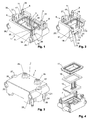
Fig. 1 is a view of an embodiment of the detector from the connector side, -
Fig. 2 is a view of the embodiment ofFig. 1 with a part sectioned off, -
Fig. 3 is a view of the embodiment ofFig. 1 from the inlet/outlet side, -
Fig. 4 is an explosive view of the embodiment ofFig. 1 , -
Fig. 5 is a view of the embodiment ofFig. 1 mounted to a support, -
Fig. 6 is a view into the (empty) hood of the embodiment ofFig. 1 from the connector side, -
Fig. 7 is a view of a second embodiment, and -
Fig. 8 is a view of the second embodiment mounted to a support. - The detector of
Figs. 1 - 6 comprises a housing generally denoted by 1 having a first side 2 (Fig. 3 ) and a second side 3 (Fig. 1 ). Aninlet 4a and anoutlet 4b (Fig. 3 ) project from first side 2, each formed by a hollow stub suited for being connected to a tube guiding the fluid. A series ofelectrical connectors 5, each formed by ametal pin 6, project perpendicularly from second side 3 of housing 1 (Fig. 1 ). - As can best be seen from
Fig. 2 ,housing 1 comprises ahood 7, which forms first side 2. Hood 7 is a single plastic piece e.g. manufactured by injection molding. Hood 7 carries at least two, advantageously fourtongues 8, which extend from second side 3. They serve to mechanically mounthousing 1 to asupport 10, such as a printed circuit board, as shown inFig. 5 . Thetongues 8 as well asinlet 4a andoutlet 4b are integrally attached tohood 7,i.e. hood 7,tongues 8,inlet 4a andoutlet 4b are a single piece of material. - As can be seen from
Fig. 2 ,hood 7 forms arecess 11, which receives aplate 12, e.g. a printed circuit board.Plate 12 carries on a first side 13 thereof, asensor chip 14.Sensor chip 14 is e.g. a thermal flow sensor such as described inUS 2002/0043710 . The backside ofsensor chip 14 lies flush againstplate 12, while the front side ofsensor chip 14, which carries the flow sensing elements, is facing aflow channel 16 that connectsinlet 4a withoutlet 4b.Plate 12 also carries theconnectors 5, which project from asecond side 14 ofplate 12. Leads onplate 12 as well as bond wires are used to electrically connect theconnectors 5 to contact pads onsensor chip 14. -
Plate 12 forms part of the second side 3 ofhousing 1. It is held inrecess 11 by aframe 17, which is also inserted intorecess 11 and has been welded to its walls.Frame 17 pushes againstsecond side 14 ofplate 12, thereby holding it in place. Asealing ring 18 of an elastic material, such as silicone, is arranged betweenframe 17 andplate 12 for preventing the fluid from exiting at second side 3 ofhousing 1.Sealing ring 18 in particular covers agap 19 between the outer rim ofplate 12 and the inner walls ofhood 7 for sealing the same.Sealing ring 18 obviates the need for a fluid tight seal right at the rims of flow channel 16 - such a seal would be difficult to achieve, in particular in the region ofsensor chip 14. -
Flow channel 16 is formed as a groove extending along an inner side of awall 20 ofhood 7.Wall 20 forms first side 2 ofhousing 1.Flow channel 16 is covered byplate 12 andsensor chip 14. - The design of the inner side of
wall 20 is best seen fromFig. 6 . Apart from the groove formingflow channel 16,wall 20 further comprises arecess 21, which serves to provide room for the bond wires and a protective glob used to connectsensor chip 14 toplate 12. - As can be seen from
Fig. 6 ,flow channel 16 extends in a plane parallel to first side 2 ofhousing 1. It has afirst end 23 connected toinlet 4a and asecond end 24 connected tooutlet 4b.First end 23 and/orsecond end 24, advantageously both of them, are looped around at least 180° ofinlet 4a andoutlet 4b, respectively. In this context, "looped around at least 180°" means that, the path of the end section is wound at least around 180° of the circumference of the inlet and outlet, respectively. - This allows to increase the actual length of
flow channel 16, which in turn decreases the risk of turbulences at the location ofsemiconductor chip 14. - Hood 7 of
housing 1 is further provided with screw holders for receiving attachment screws or attachment pins, which allow, if necessary, to mounthousing 1 more securely to a support. In the embodiment shown here, two types of screw holders are provided, which will in the following be called "first screw holders" and "second screw holders". Thefirst screw holders 26 extend parallel to first side 2 and second side 3 ofhousing 1, while thesecond screw holders 27 extend perpendicular thereto. To allow to mount thesame housing 1 in two different orientations, namely with side 3 parallel to asupport 10, such as shown inFig. 5 (where thesecond screw holders 27 can be used to attachhood 7 to base 10), or with side 3 perpendicular to support 10, such as shown in the embodiment ofFig. 8 (where thefirst screw holders 26 can be used to attachhood 7 to base 10). - As can be seen, the embodiment shown here has a total of four screw holders, namely one first and one second screw holder on a
third side 30 of housing 1 (Fig. 3 ), and one first and one second screw holder on afourth side 31 ofhousing 1, withthird side 30 being opposite tofourth side 31 and both of them being perpendicular to first side 2 and second side 3 ofhousing 1. - A larger number of screw holders could be provided as well, in particular for
large housings 1. - Each first screw holder is formed by a first through-hole through
hood 7 and eachsecond screw holder 27 is formed by a second through-hole throughhood 7. The through-holes are adapted to e.g. receive a screw or pin. In order to achieve a compact design, the first through-hole and the second through-hole on the same side ofhousing 1 intersect. - As mentioned, the
tongues 8 serve to anchorhousing 1 insupport 10 and to secure it against pulling forces. For this purpose, eachtongue 8 is provided with athin neck 34 and a thicker head 35 (Fig. 1 ).Neck 34 extends betweenhood 7 ofhousing 1 andhead 35.Head 35, whose maximum diameter exceeds the diameter ofneck 34, is wedge-shaped and tapered towards itsend 36 facing away fromhousing 1. Hence, eachtongue 8 can easily be inserted into suitably positioned andsized openings 37 in support 10 (seeFig. 5 ), where they snap in once thathead 35 has passed fully. Hence, theheads 35 form hooks that holdhousing 1 tightly insupport 10, securing it against pulling forces. - For inserting the
tongues 8 into theholes 37 ofsupport 10, the tongues need to be deformed laterally. To facilitate such a deformation, each tongue is mounted in a recessedsection 38 of the side walls ofhood 7, as shown inFigs. 1 and 3 , which allows to increase the length ofneck 34, thereby making it more resilient. - As can best be seen from
Fig. 6 , the tongues are arranged "with rotational asymmetry in respect to any axis of rotation extending through the first and second side of the housing". This is to be understood such that there is no axis of rotational symmetry perpendicular to the first and second side 2, 3 ofhousing 1. In other words, on asupport 10 parallel to first and second side 2, 3, the detector can be mounted in a single orientation only if thetongues 8 are to be inserted into theopenings 37. Thereby it can be assured that the measured signal has the correct sign and theconnector 5 is oriented properly. In the embodiment ofFig. 6 , this is achieved by placing one tongue closer to thelongitudinal axis 40 ofhousing 1 than the other tongues. - The resilience of the
necks 34 facilitates the insertion of thetongues 8 into theholes 37, but it renders thetongues 8 poorly suited to withstand lateral forces againsthousing 1. In addition to this, theholes 37 insupport 10 must have a larger diameter than thenecks 34 for allowing passage of theheads 35, which can give rise to lateral play of the fully insertedhousing 1. Hence, in addition to thetongues 8,housing 1 comprises at least one, advantageously at least two, pegs 41 projecting perpendicularly from second side 3. Thesepegs 41 can best be seen inFigs. 1 and6 . Eachpeg 41 has a diameter that remains substantially constant or decreases with increasing distance from second side 3 ofhousing 1, such that it can be inserted tightly into a suitablysized hole 42 of support 10 (Fig. 5 ). Thepegs 41 are therefore able to securehousing 1 against lateral movements in respect to support 10. - The
pegs 41 are, as thetongues 8, integrally attached tohood 7. - As mentioned, the
connectors 5 are formed by a plurality ofpins 6. In the embodiments shown here, thepins 6 are arranged in a single line. They project perpendicularly from second side 3 ofhousing 1. - If the detector is to be mounted in the position of
Fig. 5 , thepins 6 are advantageously straight such that they can be inserted into suitable openings inposition 10. - If, however, the detector is to be mounted on a
support 10 perpendicular to first side 2 and second side 3, angled pins 6' have to be used, as shown inFig. 7 and 8 . These angled pins have afirst section 10a extending substantially perpendicularly from second side 3 ofhousing 1 and asecond section 10b extending at a right angle tofirst section 10a.
Claims (17)
- A flow detector for measuring a flow of a fluid comprising
a housing (1) having opposite first and second sides (2, 3),
an inlet (4a) and an outlet (4b) for said fluid arranged at the first side (2) of said housing (1),
a flow channel (16) arranged in said housing (1) and connecting said inlet (4a) and said outlet (4b),
a sensor chip (14) arranged at a side of said flow channel (16) and adapted to measure said flow in said flow channel (16),
electrical connectors (5) connected to said sensor chip (14) for connecting said flow detector to an external system, wherein said connectors (5) extend from the second side (3) of said housing (1),
characterized by
a plurality of tongues (8), in addition to said connectors (5), extending from the second side (3) of said housing (1) for mechanically mounting said housing (1) to a support. - The flow detector of claim 1 wherein each tongue (8) comprises a head (35) and a neck (34), wherein said neck (34) extends between said second side (3) of said housing (1) and said head (35) and wherein said neck (34) has a diameter smaller than a maximum diameter of said head (35), and in particular wherein said head (35) is tapered towards an end (36) facing away from said housing (1).
- The flow detector of any of the preceding claims wherein said tongues (8) are arranged with rotational asymmetry in respect to any axis of rotation extending through said first and second side (3) of said housing (1).
- The flow detector of any of the preceding claims wherein said housing (1) comprises, in addition to said connectors (5) and said tongues (8), at least one peg (41), in particular at least two pegs, projecting perpendicularly from said second side (3) of said housing (1), wherein a diameter of said peg (41) remains constant or decreases with increasing distance from said second side (3) of said housing (1).
- The flow sensor of any of the preceding claims wherein said housing (1) comprises a hood (7) forming said first side (2) of said housing (1), wherein said tongues (8) are integrally attached to said hood (7).
- The flow sensor of the claims 4 and 5 wherein said peg or pegs (41) is/are integrally attached to said hood (7).
- The flow detector of any of the preceding claims further comprising a plate (12), in particular formed by a printed circuit board, wherein said sensor chip (14) is mounted to a first side (13) of said plate (12) and said connectors (5) project from a second side (14) of said plate (12), and in particular wherein said plate (12) forms at least part of said second side (3) of said housing (1).
- The flow detector of claim 7 wherein said sensor chip (14) lies flush against said plate (12).
- The flow detector of any of the claims 7 to 8 wherein said housing (1) comprises a hood (7) forming said first side (2) of said housing (1) and wherein said plate (12) resides in a recess of said hood (7) and is held in said recess by a frame (17) pushing towards said second side (14) of said plate (12).
- The flow detector of claim 9 further comprising a sealing ring (18), in particular a flexible sealing ring, arranged between said frame (17) and said plate (12) for preventing said fluid from exiting at said second side (3) of said housing (1).
- The flow detector of any of the claims 7 to 10 wherein said housing (1) comprises a wall (19) forming said first side (2) of said housing (1), wherein said channel (16) is formed by a groove extending at an inner side of said wall (19) and covered by said plate (12).
- The flow detector of any of the preceding claims wherein said flow channel (16) extends in a plane parallel to said first side (2) of said housing (1) and has a first end connected to said inlet (4a) and a second end connected to said outlet (4b), wherein said first end and/or said second end is/are looped around at least 180° of said inlet (4a) and/or outlet (4b), respectively.
- The flow detector of any of the preceding claims further comprising at least one first and at least one second screw holder (26, 27) for receiving an attachment screw or attachment pin, wherein said at least one first screw holder (26) extends parallel to said first and said second sides (2, 3) of said housing (1) and said at least one second screw holder (27) extends perpendicular to said first and said second sides (2, 3) of said housing (1),
and in particular wherein said flow detector comprises at least one first and at least one second screw holder (26, 27) on a third side (30) of said housing (1) and at least one first and at least one second screw holder (26, 27) on a fourth side (31) of said housing (1), wherein said fourth side (31) is opposite said third side (30). - The flow detector of claim 13 wherein said first screw holder (26) comprises a first through-hole and said second screw holder (27) comprises a second through-hole, wherein said first and said second through-holes intersect.
- The flow detector of any of the preceding claims wherein said connectors (5) comprise pins (6) projecting perpendicularly from said second side (3) of said housing.
- The flow detector of claim 15 wherein said pins (6) are straight.
- The flow detector of claim 15 wherein said pins have a first section (10a) extending perpendicularly from said second side (3) of said housing (1) and a second section (10b) extending at a right angle to said first section (10a).
Priority Applications (2)
| Application Number | Priority Date | Filing Date | Title |
|---|---|---|---|
| EP08006853.9A EP2107347B1 (en) | 2008-04-04 | 2008-04-04 | Flow detector with a housing |
| US12/383,170 US7757553B2 (en) | 2008-04-04 | 2009-03-20 | Flow detector with a housing |
Applications Claiming Priority (1)
| Application Number | Priority Date | Filing Date | Title |
|---|---|---|---|
| EP08006853.9A EP2107347B1 (en) | 2008-04-04 | 2008-04-04 | Flow detector with a housing |
Publications (2)
| Publication Number | Publication Date |
|---|---|
| EP2107347A1 true EP2107347A1 (en) | 2009-10-07 |
| EP2107347B1 EP2107347B1 (en) | 2016-08-31 |
Family
ID=40210488
Family Applications (1)
| Application Number | Title | Priority Date | Filing Date |
|---|---|---|---|
| EP08006853.9A Active EP2107347B1 (en) | 2008-04-04 | 2008-04-04 | Flow detector with a housing |
Country Status (2)
| Country | Link |
|---|---|
| US (1) | US7757553B2 (en) |
| EP (1) | EP2107347B1 (en) |
Cited By (9)
| Publication number | Priority date | Publication date | Assignee | Title |
|---|---|---|---|---|
| US10345829B2 (en) | 2015-07-17 | 2019-07-09 | Sensirion Ag | Inlet pressure perturbation insensitive mass flow controller |
| WO2019159180A1 (en) | 2018-02-19 | 2019-08-22 | Renalsense Ltd. | Sensor unit |
| EP3715158A1 (en) * | 2019-03-26 | 2020-09-30 | Valeo Systemes Thermiques | Fluid circulation housing, especially to measure particles in the fluid, air intake and heating, ventilating and/or air conditioning unit comprising said housing |
| EP2507594B1 (en) * | 2009-12-01 | 2020-10-21 | Société des Produits Nestlé S.A. | Beverage machine |
| US10942139B2 (en) | 2017-06-30 | 2021-03-09 | Sensirion Ag | Operation method for flow sensor device |
| WO2022157192A1 (en) | 2021-01-20 | 2022-07-28 | Raumedic Ag | Medical flow sensor module assembly |
| WO2023072761A1 (en) | 2021-10-29 | 2023-05-04 | Raumedic Ag | Sensor assembly for an organ transport system |
| EP4435387A1 (en) * | 2023-03-20 | 2024-09-25 | Honeywell International Inc. | Flow sensing device and associated method |
| CN118927407A (en) * | 2024-10-15 | 2024-11-12 | 江苏鹏洋节能新材料有限公司 | A mixing device for light plastering gypsum processing and use method |
Families Citing this family (17)
| Publication number | Priority date | Publication date | Assignee | Title |
|---|---|---|---|---|
| EP2175246B1 (en) * | 2008-10-09 | 2017-07-19 | Sensirion AG | A method for measuring a fluid composition parameter by means of a flow sensor |
| EP2204555B1 (en) * | 2009-01-02 | 2011-08-03 | Sensirion AG | Ammonia storage system |
| EP2406587B1 (en) * | 2009-03-10 | 2020-11-18 | Sensortechnics GmbH | Semiconductor based flow sensing device with packaging |
| US8113046B2 (en) | 2010-03-22 | 2012-02-14 | Honeywell International Inc. | Sensor assembly with hydrophobic filter |
| US8656772B2 (en) | 2010-03-22 | 2014-02-25 | Honeywell International Inc. | Flow sensor with pressure output signal |
| US8397586B2 (en) | 2010-03-22 | 2013-03-19 | Honeywell International Inc. | Flow sensor assembly with porous insert |
| US8756990B2 (en) | 2010-04-09 | 2014-06-24 | Honeywell International Inc. | Molded flow restrictor |
| US9003877B2 (en) | 2010-06-15 | 2015-04-14 | Honeywell International Inc. | Flow sensor assembly |
| US8418549B2 (en) | 2011-01-31 | 2013-04-16 | Honeywell International Inc. | Flow sensor assembly with integral bypass channel |
| US8695417B2 (en) | 2011-01-31 | 2014-04-15 | Honeywell International Inc. | Flow sensor with enhanced flow range capability |
| US9354095B2 (en) * | 2012-10-02 | 2016-05-31 | Honeywell International Inc. | Modular flow sensor |
| US9052217B2 (en) | 2012-11-09 | 2015-06-09 | Honeywell International Inc. | Variable scale sensor |
| JP5973371B2 (en) * | 2013-03-21 | 2016-08-23 | 日立オートモティブシステムズ株式会社 | Thermal flow meter |
| JP6563211B2 (en) | 2015-02-23 | 2019-08-21 | サーパス工業株式会社 | Thermal flow meter and manufacturing method thereof |
| JP6539458B2 (en) * | 2015-02-23 | 2019-07-03 | サーパス工業株式会社 | Thermal flow meter |
| US9952079B2 (en) | 2015-07-15 | 2018-04-24 | Honeywell International Inc. | Flow sensor |
| EP4467064A1 (en) * | 2023-05-25 | 2024-11-27 | Honeywell International Inc. | Devices for delivering at least one flowing media, associated sensor modules, and associated methods of mechanically and electrically coupling a sensor module to a device for delivering at least one flowing media |
Citations (5)
| Publication number | Priority date | Publication date | Assignee | Title |
|---|---|---|---|---|
| WO2001061282A2 (en) * | 2000-02-16 | 2001-08-23 | Honeywell International Inc. | Flow rate module and integrated flow restrictor |
| US20020043710A1 (en) | 2000-08-23 | 2002-04-18 | Felix Mayer | Flow sensor in a housing |
| US20040118218A1 (en) | 2002-08-27 | 2004-06-24 | Felix Mayer | Flow detector with lead-throughs and method for its production |
| US20040244511A1 (en) * | 2003-05-16 | 2004-12-09 | Gerhard Hueftle | Device for determining at least one parameter of a medium flowing in a conduit |
| US20040261522A1 (en) * | 2003-03-07 | 2004-12-30 | Dykas Thomas C | Microfluidic isolation manifold and methods for microfluidic isolation |
Family Cites Families (38)
| Publication number | Priority date | Publication date | Assignee | Title |
|---|---|---|---|---|
| US4326214A (en) * | 1976-11-01 | 1982-04-20 | National Semiconductor Corporation | Thermal shock resistant package having an ultraviolet light transmitting window for a semiconductor chip |
| US4548078A (en) | 1982-09-30 | 1985-10-22 | Honeywell Inc. | Integral flow sensor and channel assembly |
| US4677850A (en) | 1983-02-11 | 1987-07-07 | Nippon Soken, Inc. | Semiconductor-type flow rate detecting apparatus |
| US4829818A (en) | 1983-12-27 | 1989-05-16 | Honeywell Inc. | Flow sensor housing |
| US4672997A (en) | 1984-10-29 | 1987-06-16 | Btu Engineering Corporation | Modular, self-diagnostic mass-flow controller and system |
| GB8830057D0 (en) | 1988-12-23 | 1989-02-22 | Lucas Ind Plc | An electrical connection arrangement and a method of providing an electrical connection |
| US5081866A (en) | 1990-05-30 | 1992-01-21 | Yamatake-Honeywell Co., Ltd. | Respiratory air flowmeter |
| DE4038394A1 (en) | 1990-12-01 | 1992-06-04 | Bosch Gmbh Robert | ARRANGEMENT FOR SEALING A LADDER THROUGH THE WALL OF A HOUSING |
| US6002252A (en) | 1991-05-22 | 1999-12-14 | Wolff Controls Corporation | Compact sensing apparatus having transducer and signal conditioner with a plurality of mounting pins |
| JP2784286B2 (en) | 1991-12-09 | 1998-08-06 | 三菱電機株式会社 | Method for manufacturing semiconductor sensor device |
| US5228329A (en) | 1991-12-27 | 1993-07-20 | Conservation Devices, Inc. | Leak detector for fluid distribution systems serving intermittent loads |
| DE4219454C2 (en) | 1992-06-13 | 1995-09-28 | Bosch Gmbh Robert | Mass flow sensor |
| HU9402209D0 (en) | 1994-07-27 | 1994-10-28 | Magyar Gazmeroe Technika Kft | Device for consumption test and of permission gas-consumers |
| US5804717A (en) | 1996-04-05 | 1998-09-08 | Mks Instruments, Inc. | Mass flow transducer having extended flow rate measurement range |
| US5763787A (en) * | 1996-09-05 | 1998-06-09 | Rosemont Inc. | Carrier assembly for fluid sensor |
| US5750892A (en) | 1996-09-27 | 1998-05-12 | Teledyne Industries, Inc. | Laminar flow element with inboard sensor taps and coaxial laminar flow guides |
| US5944048A (en) | 1996-10-04 | 1999-08-31 | Emerson Electric Co. | Method and apparatus for detecting and controlling mass flow |
| ATE214476T1 (en) | 1996-12-17 | 2002-03-15 | Lab Fuer Physikalische Elektro | METHOD FOR APPLYING A MICROSYSTEM OR TRANSDUCER TO A SUBSTRATE AND DEVICE PRODUCABLE BY THIS METHOD |
| DE19744997A1 (en) | 1997-10-11 | 1999-04-15 | Bosch Gmbh Robert | Device for measuring the mass of a flowing medium |
| CA2310635C (en) | 1997-11-21 | 2005-01-18 | Mitsui Mining & Smelting Co., Ltd. | Flow rate sensor, temperature sensor and flow rate measuring instrument |
| US6032527A (en) | 1998-07-01 | 2000-03-07 | Memsys, Inc. | Solid state microanemometer |
| CN1515878A (en) | 1998-08-18 | 2004-07-28 | ͬ�Ϳ�ҵ��ʽ���� | Flow sensor and filter integrated flowmeter |
| US6119730A (en) | 1998-12-21 | 2000-09-19 | Mcmillan Company | Precision laminar flow element for use in thermal mass flow sensors and flow controllers |
| EP1193477A4 (en) | 1999-06-24 | 2006-10-18 | Mitsui Mining & Smelting Co | FLOW DETECTOR, FLOWMETER AND FLOW SENSOR |
| DE10191688B4 (en) | 2000-05-04 | 2010-09-16 | Sensirion Holding Ag | Sensor module and a method for its production |
| DE50107052D1 (en) | 2000-05-04 | 2005-09-15 | Sensirion Ag Zuerich | FLUID SENSOR FOR LIQUIDS |
| GB2365430B (en) * | 2000-06-08 | 2002-08-28 | Ciba Sc Holding Ag | Acylphosphine photoinitiators and intermediates |
| CH694474A5 (en) | 2000-06-23 | 2005-01-31 | Sensirion Ag | Gas meter and use of the gas meter. |
| US6591674B2 (en) | 2000-12-21 | 2003-07-15 | Honeywell International Inc. | System for sensing the motion or pressure of a fluid, the system having dimensions less than 1.5 inches, a metal lead frame with a coefficient of thermal expansion that is less than that of the body, or two rtds and a heat source |
| US6548895B1 (en) | 2001-02-21 | 2003-04-15 | Sandia Corporation | Packaging of electro-microfluidic devices |
| US6443179B1 (en) | 2001-02-21 | 2002-09-03 | Sandia Corporation | Packaging of electro-microfluidic devices |
| US6668642B2 (en) | 2001-12-21 | 2003-12-30 | Mks Instruments, Inc. | Apparatus and method for thermal isolation of thermal mass flow sensor |
| EP1351039A1 (en) | 2002-04-03 | 2003-10-08 | Sensirion AG | Flow sensor and method for producing the same |
| JP3951777B2 (en) | 2002-04-04 | 2007-08-01 | 住友電装株式会社 | Board connector |
| JP3780243B2 (en) | 2002-09-17 | 2006-05-31 | 株式会社日立製作所 | Flow rate detection device and electronic device |
| US6935144B2 (en) * | 2003-01-03 | 2005-08-30 | Council Of Scientific And Industrial Research | Device for leather processing |
| US7550319B2 (en) * | 2005-09-01 | 2009-06-23 | E. I. Du Pont De Nemours And Company | Low temperature co-fired ceramic (LTCC) tape compositions, light emitting diode (LED) modules, lighting devices and method of forming thereof |
| US7520051B2 (en) * | 2007-01-04 | 2009-04-21 | Honeywell International Inc. | Packaging methods and systems for measuring multiple measurands including bi-directional flow |
-
2008
- 2008-04-04 EP EP08006853.9A patent/EP2107347B1/en active Active
-
2009
- 2009-03-20 US US12/383,170 patent/US7757553B2/en active Active
Patent Citations (5)
| Publication number | Priority date | Publication date | Assignee | Title |
|---|---|---|---|---|
| WO2001061282A2 (en) * | 2000-02-16 | 2001-08-23 | Honeywell International Inc. | Flow rate module and integrated flow restrictor |
| US20020043710A1 (en) | 2000-08-23 | 2002-04-18 | Felix Mayer | Flow sensor in a housing |
| US20040118218A1 (en) | 2002-08-27 | 2004-06-24 | Felix Mayer | Flow detector with lead-throughs and method for its production |
| US20040261522A1 (en) * | 2003-03-07 | 2004-12-30 | Dykas Thomas C | Microfluidic isolation manifold and methods for microfluidic isolation |
| US20040244511A1 (en) * | 2003-05-16 | 2004-12-09 | Gerhard Hueftle | Device for determining at least one parameter of a medium flowing in a conduit |
Cited By (11)
| Publication number | Priority date | Publication date | Assignee | Title |
|---|---|---|---|---|
| EP2507594B1 (en) * | 2009-12-01 | 2020-10-21 | Société des Produits Nestlé S.A. | Beverage machine |
| US10345829B2 (en) | 2015-07-17 | 2019-07-09 | Sensirion Ag | Inlet pressure perturbation insensitive mass flow controller |
| US10942139B2 (en) | 2017-06-30 | 2021-03-09 | Sensirion Ag | Operation method for flow sensor device |
| WO2019159180A1 (en) | 2018-02-19 | 2019-08-22 | Renalsense Ltd. | Sensor unit |
| EP3755975A4 (en) * | 2018-02-19 | 2021-11-10 | Renalsense Ltd. | SENSOR UNIT |
| US11835366B2 (en) | 2018-02-19 | 2023-12-05 | Renalsense Ltd. | Electronic assembly for modular plug |
| EP3715158A1 (en) * | 2019-03-26 | 2020-09-30 | Valeo Systemes Thermiques | Fluid circulation housing, especially to measure particles in the fluid, air intake and heating, ventilating and/or air conditioning unit comprising said housing |
| WO2022157192A1 (en) | 2021-01-20 | 2022-07-28 | Raumedic Ag | Medical flow sensor module assembly |
| WO2023072761A1 (en) | 2021-10-29 | 2023-05-04 | Raumedic Ag | Sensor assembly for an organ transport system |
| EP4435387A1 (en) * | 2023-03-20 | 2024-09-25 | Honeywell International Inc. | Flow sensing device and associated method |
| CN118927407A (en) * | 2024-10-15 | 2024-11-12 | 江苏鹏洋节能新材料有限公司 | A mixing device for light plastering gypsum processing and use method |
Also Published As
| Publication number | Publication date |
|---|---|
| EP2107347B1 (en) | 2016-08-31 |
| US20090249869A1 (en) | 2009-10-08 |
| US7757553B2 (en) | 2010-07-20 |
Similar Documents
| Publication | Publication Date | Title |
|---|---|---|
| US7757553B2 (en) | Flow detector with a housing | |
| US7819021B2 (en) | Fluid meter | |
| ES2835649T3 (en) | Physical quantity measuring device | |
| CN104428632B (en) | flow meter | |
| CN107014557B (en) | Physical quantity measuring device | |
| JP4827961B2 (en) | Flow measuring device | |
| US20140213103A1 (en) | Adapter device with mechanical interface | |
| US20090282896A1 (en) | Connecting component for a breathing tube with a sensor for measuring the gas flow | |
| JP2001033338A (en) | Pressure sensor device | |
| CN219178628U (en) | Temperature and pressure compound sensor | |
| US20240219253A1 (en) | Adaptation Device for Coupling at least One Sensor to a Tube Shell Wall of a Tube for Fluid Measurement, and Sensor Device Having an Adaptation Device of this Type | |
| US20160313200A1 (en) | Relative Pressure Sensor | |
| US11892333B2 (en) | Flow-rate measuring device | |
| WO2025007976A1 (en) | Pressure sensor | |
| JP4726434B2 (en) | Electrical connector for pressure sensor stem | |
| US12449404B2 (en) | Ultrasonic patch transducer for monitoring the condition of a structural asset | |
| CN216251232U (en) | Aviation plug | |
| EP4040124A1 (en) | Temperature measuring device and flange assembly for securing the temperature measuring device to a fluid container | |
| CN220649631U (en) | Packaging structure of thermal flow sensor | |
| JP6986170B2 (en) | Mounting structure of coupler of electric appliance and electric appliance | |
| CN116036442B (en) | Sensor assembly of sensing device | |
| CN219551558U (en) | Digital display sensor | |
| CN111912561B (en) | A differential pressure sensor | |
| CN116086535A (en) | Temperature and pressure compound sensor | |
| CN213685753U (en) | Multi-instrument installation pipeline joint |
Legal Events
| Date | Code | Title | Description |
|---|---|---|---|
| PUAI | Public reference made under article 153(3) epc to a published international application that has entered the european phase |
Free format text: ORIGINAL CODE: 0009012 |
|
| AK | Designated contracting states |
Kind code of ref document: A1 Designated state(s): AT BE BG CH CY CZ DE DK EE ES FI FR GB GR HR HU IE IS IT LI LT LU LV MC MT NL NO PL PT RO SE SI SK TR |
|
| AX | Request for extension of the european patent |
Extension state: AL BA MK RS |
|
| 17P | Request for examination filed |
Effective date: 20100406 |
|
| AKX | Designation fees paid |
Designated state(s): DE GB |
|
| GRAP | Despatch of communication of intention to grant a patent |
Free format text: ORIGINAL CODE: EPIDOSNIGR1 |
|
| INTG | Intention to grant announced |
Effective date: 20160615 |
|
| GRAS | Grant fee paid |
Free format text: ORIGINAL CODE: EPIDOSNIGR3 |
|
| GRAA | (expected) grant |
Free format text: ORIGINAL CODE: 0009210 |
|
| AK | Designated contracting states |
Kind code of ref document: B1 Designated state(s): DE GB |
|
| REG | Reference to a national code |
Ref country code: GB Ref legal event code: FG4D |
|
| REG | Reference to a national code |
Ref country code: DE Ref legal event code: R096 Ref document number: 602008045949 Country of ref document: DE |
|
| REG | Reference to a national code |
Ref country code: DE Ref legal event code: R097 Ref document number: 602008045949 Country of ref document: DE |
|
| PLBE | No opposition filed within time limit |
Free format text: ORIGINAL CODE: 0009261 |
|
| STAA | Information on the status of an ep patent application or granted ep patent |
Free format text: STATUS: NO OPPOSITION FILED WITHIN TIME LIMIT |
|
| 26N | No opposition filed |
Effective date: 20170601 |
|
| GBPC | Gb: european patent ceased through non-payment of renewal fee |
Effective date: 20170404 |
|
| PG25 | Lapsed in a contracting state [announced via postgrant information from national office to epo] |
Ref country code: GB Free format text: LAPSE BECAUSE OF NON-PAYMENT OF DUE FEES Effective date: 20170404 |
|
| P01 | Opt-out of the competence of the unified patent court (upc) registered |
Effective date: 20230602 |
|
| PGFP | Annual fee paid to national office [announced via postgrant information from national office to epo] |
Ref country code: DE Payment date: 20250417 Year of fee payment: 18 |