EP2107204B1 - Ventilation element with adjustable elements - Google Patents
Ventilation element with adjustable elements Download PDFInfo
- Publication number
- EP2107204B1 EP2107204B1 EP09004446.2A EP09004446A EP2107204B1 EP 2107204 B1 EP2107204 B1 EP 2107204B1 EP 09004446 A EP09004446 A EP 09004446A EP 2107204 B1 EP2107204 B1 EP 2107204B1
- Authority
- EP
- European Patent Office
- Prior art keywords
- support
- blocks
- ventilating element
- outer shell
- inner shell
- Prior art date
- Legal status (The legal status is an assumption and is not a legal conclusion. Google has not performed a legal analysis and makes no representation as to the accuracy of the status listed.)
- Active
Links
Images



Classifications
-
- E—FIXED CONSTRUCTIONS
- E06—DOORS, WINDOWS, SHUTTERS, OR ROLLER BLINDS IN GENERAL; LADDERS
- E06B—FIXED OR MOVABLE CLOSURES FOR OPENINGS IN BUILDINGS, VEHICLES, FENCES OR LIKE ENCLOSURES IN GENERAL, e.g. DOORS, WINDOWS, BLINDS, GATES
- E06B7/00—Special arrangements or measures in connection with doors or windows
- E06B7/02—Special arrangements or measures in connection with doors or windows for providing ventilation, e.g. through double windows; Arrangement of ventilation roses
Definitions
- the present invention concerns a ventilating element.
- the invention concerns a ventilating element which can be placed above a window.
- Such ventilating element can be inserted through a hole in a window frame such as for instance shown in GB 2394767 , but can also be installed above a window frame, such as shown in DE 10 2006 025 372 .
- a further known ventilating element is formed of two extruded aluminium shells, i.e. an inner shell and an outer shell, which correspond to two extruded plastic shells on which the aluminium shells are provided.
- the two plastic shells can be provided on top of one another, in particular in different mutual positions, such that one and the same ventilating element can be provided on different types of windows with deviating thickness dimensions.
- the shells are provided with ribs, grooves and teeth to cooperate in an appropriate manner with glass rubbers, window jambs or other elements that are usually provided in a window.
- openings which make it possible for a flow of air to pass from the outside to the inside or vice versa.
- the present invention aims to remedy said problem.
- the ventilating element according to the invention comprises two extruded shells, namely an inner shell and an outer shell, and a support provided between the aforesaid shells, whereby the support is provided with an air passage reaching from the inner shell to the outer shell, and whereby the supports can be telescopically adjusted so as to be adapted to several wall thicknesses.
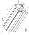
- FIGS 1 to 3 show a ventilating element 1 according to the invention.
- the ventilating element 1 mainly consists of two extruded shells, namely an inner shell 2 and an outer shell 3 respectively, designed to be provided on the inside and the outside of the building.
- a support 4 Between both shells 2 and 3 is provided a support 4. In the support 4 is provided an air passage 5 which reaches from the inner shell 2 to the outer shell 3.
- the plastic support 4 is made in two parts here and thus comprises a first block 6 on which the inner shell 2 is provided, and a second block 7 on which the outer shell 3 is provided.
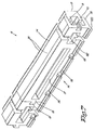
- the second block 7 has a 3D design here with a variable section in its longitudinal direction, corresponding with the 3D design of the first block 6 which also has a variable section in its longitudinal direction, such that both blocks 6 and 7 can be fixed and clamped to one another in various positions in order to obtain an adjustable total width B of the support 4.
- the first block 6 can be regarded as a jamb with a predominantly U-shaped section, with a back 8 and legs 9 and 10, whereby the back 8 is provided with a recess 12 in the central part 11.
- the second block 7 can be regarded as a jamb with a predominantly U-shaped section, with a back 13 and legs 14 and 15, whereby the back 13 is provided with a recess 17 in the central part 16.
- the back 8, the legs 9 and 10, the back 13 and the legs 14 are thick-walled or in this case massive, in particular with thicknesses of more than 2 mm, in this case between 5 mm and 30 mm.
- a few water discharge channels 18 reach from the inner part of the recess 17 to the connection of the back 13 with the leg 15 situated at the bottom.
- the inner walls of the legs 14 and 15 are situated at a distance D2, which corresponds in an appropriate manner with or is even somewhat smaller than the outside dimension D1 of the first block 6, such that they can be clamped together.
- the blocks 6 and 7 have such a design on the outside, in particular with a few edges 19, and near the transition from the back 13 into the leg 15 they have a shoulder 20 corresponding with the inner shell 2 and the outer shell 3 and designed to fix the latter on the blocks 6 and 7.
- Said inner shell 2 is provided to that end with a first pair of protruding flanks 21 which, as is shown in figures 1 to 3 , co-operate in an appropriate manner with the outside of the first block 6, and with a second pair of protruding flanks 22, the topmost flank 22 of which cooperates in an appropriate manner with the outside of the second block 7, and whose bottommost flank 22 is provided with teeth 23 to co-operate with a plastic fixing post 24 between the inner shell 2 and the outer shell 3.
- the inner shell 2 In line with the air passage 5, the inner shell 2 is provided with a recess 25 and further in line therewith with a rotating stop valve 26.
- the outer shell 3 is provided, in line with the air passage 5 there, with a recess 27 and in line therewith with a self-regulating stop valve 28 made of plastic.
- This self-regulating stop valve 28 is provided in a rotating manner in a screening cap 29 provided on the outer shell 3 by means of what is called a clip connection 30.
- the self-regulating stop valve 28 is predominantly Y-shaped.
- the working of the ventilating element 1 according to the invention is simple and as follows.
- the ventilating element 1 When there are no stop valves 26 and 28, the ventilating element 1 according to the invention provides for an isolated element which, in the orientation as shown, can be provided above a window jamb in which is provided a passage 5 which connects to openings 26 and 27 in the aluminium shells 2 and 3 forming a housing of the ventilating element 1.
- Air can then be moved unhindered from the inside to the outside, or vice versa, depending on the differential pressure over the inside and the outside of the building.
- the ventilating element 1 When there is an equilibrium of pressure, the ventilating element 1, for the time being still being considered without any stop valves 26 and 28, would form a good insulating element, but without any particular use however.
- the blocks 6 and 7 and the plastic fixing post 24 between the inner shell 2 and the outer shell 3 provide for a good insulation between the inside and the outside of the building on the one hand, and between the ventilating element 1 and the window jamb on the other hand.
- the plastic fixing post 24 thereby maintains the thermal separation between an inner frame and an outer frame of a usually underlying window.
- the blocks 6 and 7 are clamped onto one another, which allows for a telescopic adjustment which may be optionally variable.
- the used hard foam in this case hard EPS, is advantageous in that it is a relatively hard plastic, but nevertheless sufficiently flexible and deformable or compressible, which makes it possible to provide a mould with limited tolerances of for example 0.1 mm.
- the support 4 is thick-walled in this case, such that the structure as a whole offers sufficient rigidity.
- the walls in particular have a thickness larger than 2 mm, and preferably larger than 3 mm, in this case in particular between 5 and 30 mm, but depending on the dimensions of the ventilating element 1, the used plastic or the required characteristics, sizes may vary.
- This characteristic offers the advantage that the used material must not have the same strength as the materials that are usually applied, such as PVC.
- the support 4 can be made of a strongly insulating material which is easy to process, which are important qualities for the present application.
- This lifting is procured by the differential pressure between the outside and the inside and possibly also by any additional changes in pressure caused by the air flow itself and the specific rendering of the ventilating element 1 there, among others due to the venturi action at the self-regulating stop valve 28.
- the self-regulating stop valve 28 has a special distribution of weight in relation to its hinge pin.
- the specific Y-shaped section makes sure here that the centre of gravity of the self-regulating stop valve 28 is mainly situated on the leg with which the self-regulating stop valve 28 is hinge-mounted.
- the counterweight increases as the self-regulating stop valve 28 is tilted as a result of an overpressure on the outside of the ventilating element 1. This prevents it from closing off too quickly.
- the stop valve 26 makes it possible to close off the air passage 5 manually from the inside.
- the blocks 6 and 7 are provided with fastening means 31 on one or on both free ends, in this case in the shape of a tooth or a groove in the shape of a dovetail directed crosswise to the longitudinal direction of the blocks 6 and 7.
- Said fastening means 31 make it possible to extend the support 4 by connecting blocks 6 or 7 with one another, or by providing adapters, connecting pieces or end parts or the like on the latter.
- Additional recesses 32 may also be provided at the far ends which may serve as parts of the air passage 5.
- first block 6 is provided with a tooth or a groove 31 on at least one far end
- second block 7 is provided with a tooth or a groove 31 on at least the other far end
- this will make it possible to saw the blocks 6 and 7 at the required lengths and to provide an extension piece, an end part or a connecting piece on both far ends which must then be provided with a corresponding groove or tooth.
- the blocks 6 and 7 are sawn on the free ends that are moved away from one another, such that the support 4, when the blocks 6 and 7 are joined after having been sawn, is still provided with connecting means on each of the free ends, be it then only on one of the blocks 6 and 7.
- ventilating elements 1 with an arbitrary length, whereby they can still be provided with an extension piece, an end part or a connecting piece or the like on both free ends.
- the blocks 6 and 7 are clamped onto one another, which offers the possibility, in case of a crossed mutual positioning, to extend the blocks with additional blocks or to provide them with adapters, connecting pieces or end parts or the like.
- the clamping co-operation between the blocks 6 and 7 allows for a telescopic adjustment, which may be optionally variable, but it is clear that this adjustability for a given support 4 is restricted to a certain interval.
- the support 4 or the blocks 6 and 7 can be made in different lengths, for example in lengths of one metre.
- a support 4 can be made of various materials, or that a single support 4 can be composed of different materials.
- the inner shell 2 as well as the outer shell 3 can be provided with connecting means to apply numerous accessories, such as an insect netting or a pollen filter which are preferably replaceable, external operation means, a fan, sound deadening means or heat recycling means.
- an insect netting or a pollen filter which are preferably replaceable, external operation means, a fan, sound deadening means or heat recycling means.
Landscapes
- Engineering & Computer Science (AREA)
- Civil Engineering (AREA)
- Structural Engineering (AREA)
- Specific Sealing Or Ventilating Devices For Doors And Windows (AREA)
- Catching Or Destruction (AREA)
Abstract
Description
- The present invention concerns a ventilating element.
- In particular, the invention concerns a ventilating element which can be placed above a window.
- Such ventilating element can be inserted through a hole in a window frame such as for instance shown in
GB 2394767 DE 10 2006 025 372 - A further known ventilating element is formed of two extruded aluminium shells, i.e. an inner shell and an outer shell, which correspond to two extruded plastic shells on which the aluminium shells are provided.
- The two plastic shells can be provided on top of one another, in particular in different mutual positions, such that one and the same ventilating element can be provided on different types of windows with deviating thickness dimensions.
- The shells are provided with ribs, grooves and teeth to cooperate in an appropriate manner with glass rubbers, window jambs or other elements that are usually provided in a window.
- In the aluminium jambs and in the supports are provided openings which make it possible for a flow of air to pass from the outside to the inside or vice versa.
- However, these last-mentioned known ventilating elements require the supports to be adjusted to the different wall thickness that must be spanned.
- The present invention aims to remedy said problem.
- To this end, the ventilating element according to the invention comprises two extruded shells, namely an inner shell and an outer shell, and a support provided between the aforesaid shells, whereby the support is provided with an air passage reaching from the inner shell to the outer shell, and whereby the supports can be telescopically adjusted so as to be adapted to several wall thicknesses.
- In order to better explain the characteristics of the invention, the following preferred embodiments are described by way of example only without being limitative in any way, with reference to the accompanying drawings, in which:
-
figures 1 and2 show a ventilating element according to the invention, seen in perspective from different angles; -
figure 3 shows a section according to line III-III infigure 1 ; -
figures 4 and5 show the part, indicated by arrow F4 infigure 1 , seen in perspective from different angles; -
figures 6 and7 show an alternative embodiment of the part, indicated by arrow F4 infigure 1 , seen in perspective from different angles. -
Figures 1 to 3 show a ventilating element 1 according to the invention. - The ventilating element 1 mainly consists of two extruded shells, namely an
inner shell 2 and an outer shell 3 respectively, designed to be provided on the inside and the outside of the building. - Between both
shells 2 and 3 is provided a support 4. In the support 4 is provided an air passage 5 which reaches from theinner shell 2 to the outer shell 3. - The plastic support 4 is made in two parts here and thus comprises a
first block 6 on which theinner shell 2 is provided, and a second block 7 on which the outer shell 3 is provided. - The second block 7 has a 3D design here with a variable section in its longitudinal direction, corresponding with the 3D design of the
first block 6 which also has a variable section in its longitudinal direction, such that bothblocks 6 and 7 can be fixed and clamped to one another in various positions in order to obtain an adjustable total width B of the support 4. - The 3D design of both
blocks 6 and 7 is illustrated infigures 4 and5 . - The
first block 6 can be regarded as a jamb with a predominantly U-shaped section, with aback 8 andlegs 9 and 10, whereby theback 8 is provided with arecess 12 in the central part 11. - The outer walls of these
legs 9 and 10 are situated at a distance D1. - The second block 7 can be regarded as a jamb with a predominantly U-shaped section, with a
back 13 andlegs back 13 is provided with arecess 17 in thecentral part 16. - The
back 8, thelegs 9 and 10, theback 13 and thelegs 14 are thick-walled or in this case massive, in particular with thicknesses of more than 2 mm, in this case between 5 mm and 30 mm. - A few
water discharge channels 18 reach from the inner part of therecess 17 to the connection of theback 13 with theleg 15 situated at the bottom. - The inner walls of the
legs first block 6, such that they can be clamped together. - The
blocks 6 and 7 have such a design on the outside, in particular with afew edges 19, and near the transition from theback 13 into theleg 15 they have ashoulder 20 corresponding with theinner shell 2 and the outer shell 3 and designed to fix the latter on theblocks 6 and 7. - Said
inner shell 2 is provided to that end with a first pair of protruding flanks 21 which, as is shown infigures 1 to 3 , co-operate in an appropriate manner with the outside of thefirst block 6, and with a second pair of protrudingflanks 22, thetopmost flank 22 of which cooperates in an appropriate manner with the outside of the second block 7, and whosebottommost flank 22 is provided with teeth 23 to co-operate with aplastic fixing post 24 between theinner shell 2 and the outer shell 3. - In line with the air passage 5, the
inner shell 2 is provided with arecess 25 and further in line therewith with a rotatingstop valve 26. - In analogy with what precedes, also the outer shell 3 is provided, in line with the air passage 5 there, with a recess 27 and in line therewith with a self-regulating
stop valve 28 made of plastic. - This self-regulating
stop valve 28 is provided in a rotating manner in ascreening cap 29 provided on the outer shell 3 by means of what is called aclip connection 30. - The self-regulating
stop valve 28 is predominantly Y-shaped. - The working of the ventilating element 1 according to the invention is simple and as follows.
- When there are no
stop valves openings 26 and 27 in thealuminium shells 2 and 3 forming a housing of the ventilating element 1. - Air can then be moved unhindered from the inside to the outside, or vice versa, depending on the differential pressure over the inside and the outside of the building.
- When there is an equilibrium of pressure, the ventilating element 1, for the time being still being considered without any
stop valves - Indeed, the
blocks 6 and 7 and theplastic fixing post 24 between theinner shell 2 and the outer shell 3 provide for a good insulation between the inside and the outside of the building on the one hand, and between the ventilating element 1 and the window jamb on the other hand. - The
plastic fixing post 24 thereby maintains the thermal separation between an inner frame and an outer frame of a usually underlying window. - The
blocks 6 and 7 are clamped onto one another, which allows for a telescopic adjustment which may be optionally variable. - The used hard foam, in this case hard EPS, is advantageous in that it is a relatively hard plastic, but nevertheless sufficiently flexible and deformable or compressible, which makes it possible to provide a mould with limited tolerances of for example 0.1 mm.
- The support 4 is thick-walled in this case, such that the structure as a whole offers sufficient rigidity. The walls in particular have a thickness larger than 2 mm, and preferably larger than 3 mm, in this case in particular between 5 and 30 mm, but depending on the dimensions of the ventilating element 1, the used plastic or the required characteristics, sizes may vary.
- This characteristic offers the advantage that the used material must not have the same strength as the materials that are usually applied, such as PVC.
- Thanks to said characteristic, the support 4 can be made of a strongly insulating material which is easy to process, which are important qualities for the present application.
- In what follows, the
stop valves - Thanks to the presence of the self-regulating
stop valve 28, the free flow of air from the outside to the inside will be restricted in case of a differential pressure. - Indeed, as the overpressure between the outside and the inside increases, for example due to the influence of the wind, the tendency for the free flow of air to increase through the air passage is restricted as the self-regulating
stop valve 28 is lifted. - This lifting is procured by the differential pressure between the outside and the inside and possibly also by any additional changes in pressure caused by the air flow itself and the specific rendering of the ventilating element 1 there, among others due to the venturi action at the self-regulating
stop valve 28. - To this end, the self-regulating
stop valve 28 has a special distribution of weight in relation to its hinge pin. - In particular, the specific Y-shaped section makes sure here that the centre of gravity of the self-regulating
stop valve 28 is mainly situated on the leg with which the self-regulatingstop valve 28 is hinge-mounted. - The counterweight increases as the self-regulating
stop valve 28 is tilted as a result of an overpressure on the outside of the ventilating element 1. This prevents it from closing off too quickly. - The
stop valve 26 makes it possible to close off the air passage 5 manually from the inside. - According to a special embodiment, represented in
figures 6 and7 , theblocks 6 and 7 are provided withfastening means 31 on one or on both free ends, in this case in the shape of a tooth or a groove in the shape of a dovetail directed crosswise to the longitudinal direction of theblocks 6 and 7. - Said fastening means 31 make it possible to extend the support 4 by connecting
blocks 6 or 7 with one another, or by providing adapters, connecting pieces or end parts or the like on the latter. -
Additional recesses 32 may also be provided at the far ends which may serve as parts of the air passage 5. - When a
first block 6 is provided with a tooth or agroove 31 on at least one far end, whereas the second block 7 is provided with a tooth or agroove 31 on at least the other far end, this will make it possible to saw theblocks 6 and 7 at the required lengths and to provide an extension piece, an end part or a connecting piece on both far ends which must then be provided with a corresponding groove or tooth. - To that end, the
blocks 6 and 7 are sawn on the free ends that are moved away from one another, such that the support 4, when theblocks 6 and 7 are joined after having been sawn, is still provided with connecting means on each of the free ends, be it then only on one of theblocks 6 and 7. - This makes it possible to provide ventilating elements 1 with an arbitrary length, whereby they can still be provided with an extension piece, an end part or a connecting piece or the like on both free ends.
- Besides, the
blocks 6 and 7 are clamped onto one another, which offers the possibility, in case of a crossed mutual positioning, to extend the blocks with additional blocks or to provide them with adapters, connecting pieces or end parts or the like. - The clamping co-operation between the
blocks 6 and 7 allows for a telescopic adjustment, which may be optionally variable, but it is clear that this adjustability for a given support 4 is restricted to a certain interval. - It is clear that the
blocks 6 and 7 can also be integrated and made in one piece. This results in a cheaper but less flexible support 4. - The support 4 or the
blocks 6 and 7 can be made in different lengths, for example in lengths of one metre. - It is also clear that a support 4 can be made of various materials, or that a single support 4 can be composed of different materials.
- The
inner shell 2 as well as the outer shell 3 can be provided with connecting means to apply numerous accessories, such as an insect netting or a pollen filter which are preferably replaceable, external operation means, a fan, sound deadening means or heat recycling means. - The present invention is by no means restricted to the embodiments described by way of example and represented in the accompanying drawings; on the contrary, such a ventilating element according to the invention can be made in many different shapes and dimensions while still remaining within the scope of the invention as defined by the appended claims.
Claims (7)
- Ventilating element to form a ventilating passage between two spaces comprising two extruded shells, namely an inner shell (2) and an outer shell (3), and a support (4) provided between the aforesaid shells (2,3), whereby the support (4) is provided with an air passage (5) reaching from the inner shell (2) to the outer shell (3), and whereby the support (4) is built of two blocks (6 and 7) on which are respectively provided the inner shell and the outer shell, characterised in that the two blocks are telescopically adjustable.
- Ventilating element according to claim 1, characterised in that the support (4) comprises walls with a thickness of more than 2 mm.
- Ventilating element according to claim 1, characterised in that the support (4) comprises walls with a thickness of more than 5 mm.
- Ventilating element according to one or several of the preceding claims, characterised in that the support (4) is provided with water discharge channels (18).
- Ventilating element according to one or several of the preceding claims, characterised in that between the inner shell (2) and the outer shell (3) is provided a plastic fixing post (24).
- Ventilating element according to one or several of the preceding claims, characterised in that the support (4), or if necessary at least one of the blocks (6,7), is provided with fastening means on at least one of its free ends for fixing an end part, a connecting piece or an extension piece or the like.
- Ventilating element according to claims 9 and 2, characterised in that the first block (6) is provided with fastening means on one far end, whereas the second block (7) is provided with fastening means on the other far end.
Priority Applications (1)
| Application Number | Priority Date | Filing Date | Title |
|---|---|---|---|
| PL09004446T PL2107204T3 (en) | 2008-04-03 | 2009-03-27 | Ventilation element with adjustable elements |
Applications Claiming Priority (1)
| Application Number | Priority Date | Filing Date | Title |
|---|---|---|---|
| BE2008/0208A BE1018086A5 (en) | 2008-04-03 | 2008-04-03 | VENTILATION ELEMENT AND METHOD FOR MANUFACTURING IT. |
Publications (3)
| Publication Number | Publication Date |
|---|---|
| EP2107204A1 EP2107204A1 (en) | 2009-10-07 |
| EP2107204A8 EP2107204A8 (en) | 2009-12-09 |
| EP2107204B1 true EP2107204B1 (en) | 2013-12-18 |
Family
ID=40002944
Family Applications (1)
| Application Number | Title | Priority Date | Filing Date |
|---|---|---|---|
| EP09004446.2A Active EP2107204B1 (en) | 2008-04-03 | 2009-03-27 | Ventilation element with adjustable elements |
Country Status (5)
| Country | Link |
|---|---|
| EP (1) | EP2107204B1 (en) |
| BE (1) | BE1018086A5 (en) |
| ES (1) | ES2445153T3 (en) |
| PL (1) | PL2107204T3 (en) |
| PT (1) | PT2107204E (en) |
Cited By (1)
| Publication number | Priority date | Publication date | Assignee | Title |
|---|---|---|---|---|
| EP2886780A1 (en) * | 2013-12-17 | 2015-06-24 | MACO Technologie GmbH | Window rebate ventilator |
Families Citing this family (2)
| Publication number | Priority date | Publication date | Assignee | Title |
|---|---|---|---|---|
| DE102014007842A1 (en) * | 2014-05-22 | 2015-11-26 | Roto Frank Ag | Insulating block for a window or the like |
| BE1028363B1 (en) * | 2020-06-01 | 2022-01-11 | Renson Ventilation Nv | FRAME CONSTRUCTION WITH VENTILATION DEVICE |
Family Cites Families (5)
| Publication number | Priority date | Publication date | Assignee | Title |
|---|---|---|---|---|
| DE3301508C2 (en) * | 1982-03-11 | 1985-01-17 | Siegenia-Frank Kg, 5900 Siegen | Ventilation device for installation in windows and / or other wall openings in buildings |
| DE19723485C2 (en) * | 1997-06-05 | 2003-05-22 | Michael Schwarz | Device for ventilating rooms |
| DE19751959A1 (en) * | 1997-11-24 | 1999-06-02 | Christian Hirschfelder | Acoustic insulation for window of building |
| GB0302805D0 (en) * | 2003-02-07 | 2003-03-12 | Harding Jane C M | Window vent |
| DE102006025372A1 (en) * | 2006-05-31 | 2007-12-06 | Josef Hain Gmbh & Co. Kg | Window e.g. basement window, for use in building, has kit with upper and lower parts screwed with each other and sealed together in water-tight manner, where each part has sash fastened at or in parts and fills frame opening |
-
2008
- 2008-04-03 BE BE2008/0208A patent/BE1018086A5/en not_active IP Right Cessation
-
2009
- 2009-03-27 EP EP09004446.2A patent/EP2107204B1/en active Active
- 2009-03-27 PL PL09004446T patent/PL2107204T3/en unknown
- 2009-03-27 ES ES09004446.2T patent/ES2445153T3/en active Active
- 2009-03-27 PT PT90044462T patent/PT2107204E/en unknown
Cited By (2)
| Publication number | Priority date | Publication date | Assignee | Title |
|---|---|---|---|---|
| EP2886780A1 (en) * | 2013-12-17 | 2015-06-24 | MACO Technologie GmbH | Window rebate ventilator |
| DE102013114250A1 (en) * | 2013-12-17 | 2015-07-02 | Maco Technologie Gmbh | Falzlüfter |
Also Published As
| Publication number | Publication date |
|---|---|
| BE1018086A5 (en) | 2010-05-04 |
| EP2107204A8 (en) | 2009-12-09 |
| PT2107204E (en) | 2014-01-08 |
| ES2445153T3 (en) | 2014-02-28 |
| EP2107204A1 (en) | 2009-10-07 |
| PL2107204T3 (en) | 2014-05-30 |
Similar Documents
| Publication | Publication Date | Title |
|---|---|---|
| KR101027310B1 (en) | Multifunctional sliding gap guard of sliding window | |
| US20080196342A1 (en) | Thermal composite window | |
| KR102060165B1 (en) | Glass handrail and window having the same | |
| KR20150000653U (en) | Project windows with enhanced insulation | |
| EP2107204A1 (en) | Ventilation element with adjustable elements | |
| EP2299016B1 (en) | Door frame set and door assembly | |
| US5802785A (en) | Aluminum framed window molding | |
| GB2194038A (en) | Window vent | |
| JP7057231B2 (en) | Joinery | |
| KR101318730B1 (en) | Complex casement window | |
| JP2023123840A5 (en) | sash window | |
| KR200281154Y1 (en) | Structure for soundproof and protection against wind of a sash | |
| US5901509A (en) | Component for a window frame | |
| KR101516008B1 (en) | Size variable door | |
| CN205778381U (en) | A kind of entry door | |
| JP7773870B2 (en) | Shoji screens and fittings | |
| EP1654432B1 (en) | Profile of a window frame or the like | |
| EP1691022A2 (en) | Corner piece and joinery which is provided with such a corner piece | |
| KR20170035685A (en) | Natural ventilating apparatus | |
| USRE24704E (en) | kunkel | |
| EP2362053A1 (en) | Adjustable counter-frame for door and window fittings | |
| KR100870240B1 (en) | Door frame and window frame structure with plate | |
| JP2004293245A (en) | Building profile | |
| RU23310U1 (en) | WINDOW WITH A VENTILATION DEVICE | |
| EP2975206A1 (en) | Reinforced profile for sash frames and set of profiles for window frames and sash frames |
Legal Events
| Date | Code | Title | Description |
|---|---|---|---|
| PUAI | Public reference made under article 153(3) epc to a published international application that has entered the european phase |
Free format text: ORIGINAL CODE: 0009012 |
|
| AK | Designated contracting states |
Kind code of ref document: A1 Designated state(s): AT BE BG CH CY CZ DE DK EE ES FI FR GB GR HR HU IE IS IT LI LT LU LV MC MK MT NL NO PL PT RO SE SI SK TR |
|
| AX | Request for extension of the european patent |
Extension state: AL BA RS |
|
| RAP1 | Party data changed (applicant data changed or rights of an application transferred) |
Owner name: KLIMADELTA GMBH Owner name: VAN PARYS, REMI EMIEL |
|
| 17P | Request for examination filed |
Effective date: 20091204 |
|
| AKX | Designation fees paid |
Designated state(s): AT BE BG CH CY CZ DE DK EE ES FI FR GB GR HR HU IE IS IT LI LT LU LV MC MK MT NL NO PL PT RO SE SI SK TR |
|
| 17Q | First examination report despatched |
Effective date: 20120727 |
|
| GRAP | Despatch of communication of intention to grant a patent |
Free format text: ORIGINAL CODE: EPIDOSNIGR1 |
|
| INTG | Intention to grant announced |
Effective date: 20130624 |
|
| GRAS | Grant fee paid |
Free format text: ORIGINAL CODE: EPIDOSNIGR3 |
|
| GRAA | (expected) grant |
Free format text: ORIGINAL CODE: 0009210 |
|
| AK | Designated contracting states |
Kind code of ref document: B1 Designated state(s): AT BE BG CH CY CZ DE DK EE ES FI FR GB GR HR HU IE IS IT LI LT LU LV MC MK MT NL NO PL PT RO SE SI SK TR |
|
| RAP1 | Party data changed (applicant data changed or rights of an application transferred) |
Owner name: SOBINCO NV Owner name: VAN PARYS, REMI EMIEL |
|
| REG | Reference to a national code |
Ref country code: GB Ref legal event code: FG4D |
|
| REG | Reference to a national code |
Ref country code: CH Ref legal event code: EP |
|
| REG | Reference to a national code |
Ref country code: PT Ref legal event code: SC4A Free format text: AVAILABILITY OF NATIONAL TRANSLATION Effective date: 20131231 |
|
| REG | Reference to a national code |
Ref country code: AT Ref legal event code: REF Ref document number: 645743 Country of ref document: AT Kind code of ref document: T Effective date: 20140115 |
|
| REG | Reference to a national code |
Ref country code: NL Ref legal event code: T3 Ref country code: IE Ref legal event code: FG4D |
|
| REG | Reference to a national code |
Ref country code: NL Ref legal event code: T3 |
|
| REG | Reference to a national code |
Ref country code: DE Ref legal event code: R096 Ref document number: 602009020782 Country of ref document: DE Effective date: 20140213 |
|
| REG | Reference to a national code |
Ref country code: ES Ref legal event code: FG2A Ref document number: 2445153 Country of ref document: ES Kind code of ref document: T3 Effective date: 20140228 |
|
| PG25 | Lapsed in a contracting state [announced via postgrant information from national office to epo] |
Ref country code: HR Free format text: LAPSE BECAUSE OF FAILURE TO SUBMIT A TRANSLATION OF THE DESCRIPTION OR TO PAY THE FEE WITHIN THE PRESCRIBED TIME-LIMIT Effective date: 20131218 Ref country code: NO Free format text: LAPSE BECAUSE OF FAILURE TO SUBMIT A TRANSLATION OF THE DESCRIPTION OR TO PAY THE FEE WITHIN THE PRESCRIBED TIME-LIMIT Effective date: 20140318 Ref country code: LT Free format text: LAPSE BECAUSE OF FAILURE TO SUBMIT A TRANSLATION OF THE DESCRIPTION OR TO PAY THE FEE WITHIN THE PRESCRIBED TIME-LIMIT Effective date: 20131218 Ref country code: SE Free format text: LAPSE BECAUSE OF FAILURE TO SUBMIT A TRANSLATION OF THE DESCRIPTION OR TO PAY THE FEE WITHIN THE PRESCRIBED TIME-LIMIT Effective date: 20131218 Ref country code: FI Free format text: LAPSE BECAUSE OF FAILURE TO SUBMIT A TRANSLATION OF THE DESCRIPTION OR TO PAY THE FEE WITHIN THE PRESCRIBED TIME-LIMIT Effective date: 20131218 |
|
| REG | Reference to a national code |
Ref country code: LT Ref legal event code: MG4D |
|
| PG25 | Lapsed in a contracting state [announced via postgrant information from national office to epo] |
Ref country code: LV Free format text: LAPSE BECAUSE OF FAILURE TO SUBMIT A TRANSLATION OF THE DESCRIPTION OR TO PAY THE FEE WITHIN THE PRESCRIBED TIME-LIMIT Effective date: 20131218 |
|
| REG | Reference to a national code |
Ref country code: PL Ref legal event code: T3 |
|
| PG25 | Lapsed in a contracting state [announced via postgrant information from national office to epo] |
Ref country code: EE Free format text: LAPSE BECAUSE OF FAILURE TO SUBMIT A TRANSLATION OF THE DESCRIPTION OR TO PAY THE FEE WITHIN THE PRESCRIBED TIME-LIMIT Effective date: 20131218 Ref country code: IS Free format text: LAPSE BECAUSE OF FAILURE TO SUBMIT A TRANSLATION OF THE DESCRIPTION OR TO PAY THE FEE WITHIN THE PRESCRIBED TIME-LIMIT Effective date: 20140418 |
|
| PG25 | Lapsed in a contracting state [announced via postgrant information from national office to epo] |
Ref country code: CZ Free format text: LAPSE BECAUSE OF FAILURE TO SUBMIT A TRANSLATION OF THE DESCRIPTION OR TO PAY THE FEE WITHIN THE PRESCRIBED TIME-LIMIT Effective date: 20131218 Ref country code: CY Free format text: LAPSE BECAUSE OF FAILURE TO SUBMIT A TRANSLATION OF THE DESCRIPTION OR TO PAY THE FEE WITHIN THE PRESCRIBED TIME-LIMIT Effective date: 20131218 Ref country code: RO Free format text: LAPSE BECAUSE OF FAILURE TO SUBMIT A TRANSLATION OF THE DESCRIPTION OR TO PAY THE FEE WITHIN THE PRESCRIBED TIME-LIMIT Effective date: 20131218 Ref country code: SK Free format text: LAPSE BECAUSE OF FAILURE TO SUBMIT A TRANSLATION OF THE DESCRIPTION OR TO PAY THE FEE WITHIN THE PRESCRIBED TIME-LIMIT Effective date: 20131218 |
|
| REG | Reference to a national code |
Ref country code: DE Ref legal event code: R097 Ref document number: 602009020782 Country of ref document: DE |
|
| PLBE | No opposition filed within time limit |
Free format text: ORIGINAL CODE: 0009261 |
|
| STAA | Information on the status of an ep patent application or granted ep patent |
Free format text: STATUS: NO OPPOSITION FILED WITHIN TIME LIMIT |
|
| PG25 | Lapsed in a contracting state [announced via postgrant information from national office to epo] |
Ref country code: LU Free format text: LAPSE BECAUSE OF FAILURE TO SUBMIT A TRANSLATION OF THE DESCRIPTION OR TO PAY THE FEE WITHIN THE PRESCRIBED TIME-LIMIT Effective date: 20140327 Ref country code: DK Free format text: LAPSE BECAUSE OF FAILURE TO SUBMIT A TRANSLATION OF THE DESCRIPTION OR TO PAY THE FEE WITHIN THE PRESCRIBED TIME-LIMIT Effective date: 20131218 |
|
| REG | Reference to a national code |
Ref country code: CH Ref legal event code: PL |
|
| 26N | No opposition filed |
Effective date: 20140919 |
|
| REG | Reference to a national code |
Ref country code: IE Ref legal event code: MM4A Ref country code: DE Ref legal event code: R097 Ref document number: 602009020782 Country of ref document: DE Effective date: 20140919 |
|
| PG25 | Lapsed in a contracting state [announced via postgrant information from national office to epo] |
Ref country code: IE Free format text: LAPSE BECAUSE OF NON-PAYMENT OF DUE FEES Effective date: 20140327 Ref country code: CH Free format text: LAPSE BECAUSE OF NON-PAYMENT OF DUE FEES Effective date: 20140331 Ref country code: LI Free format text: LAPSE BECAUSE OF NON-PAYMENT OF DUE FEES Effective date: 20140331 |
|
| PG25 | Lapsed in a contracting state [announced via postgrant information from national office to epo] |
Ref country code: SI Free format text: LAPSE BECAUSE OF FAILURE TO SUBMIT A TRANSLATION OF THE DESCRIPTION OR TO PAY THE FEE WITHIN THE PRESCRIBED TIME-LIMIT Effective date: 20131218 |
|
| REG | Reference to a national code |
Ref country code: FR Ref legal event code: PLFP Year of fee payment: 8 |
|
| PG25 | Lapsed in a contracting state [announced via postgrant information from national office to epo] |
Ref country code: MT Free format text: LAPSE BECAUSE OF FAILURE TO SUBMIT A TRANSLATION OF THE DESCRIPTION OR TO PAY THE FEE WITHIN THE PRESCRIBED TIME-LIMIT Effective date: 20131218 |
|
| PGFP | Annual fee paid to national office [announced via postgrant information from national office to epo] |
Ref country code: FR Payment date: 20151221 Year of fee payment: 8 |
|
| PGFP | Annual fee paid to national office [announced via postgrant information from national office to epo] |
Ref country code: NL Payment date: 20151221 Year of fee payment: 8 |
|
| PGFP | Annual fee paid to national office [announced via postgrant information from national office to epo] |
Ref country code: IT Payment date: 20160223 Year of fee payment: 8 Ref country code: DE Payment date: 20151221 Year of fee payment: 8 |
|
| PG25 | Lapsed in a contracting state [announced via postgrant information from national office to epo] |
Ref country code: MC Free format text: LAPSE BECAUSE OF FAILURE TO SUBMIT A TRANSLATION OF THE DESCRIPTION OR TO PAY THE FEE WITHIN THE PRESCRIBED TIME-LIMIT Effective date: 20131218 |
|
| PGFP | Annual fee paid to national office [announced via postgrant information from national office to epo] |
Ref country code: GB Payment date: 20160115 Year of fee payment: 8 Ref country code: PL Payment date: 20160107 Year of fee payment: 8 Ref country code: AT Payment date: 20160218 Year of fee payment: 8 |
|
| PG25 | Lapsed in a contracting state [announced via postgrant information from national office to epo] |
Ref country code: BG Free format text: LAPSE BECAUSE OF FAILURE TO SUBMIT A TRANSLATION OF THE DESCRIPTION OR TO PAY THE FEE WITHIN THE PRESCRIBED TIME-LIMIT Effective date: 20131218 Ref country code: GR Free format text: LAPSE BECAUSE OF FAILURE TO SUBMIT A TRANSLATION OF THE DESCRIPTION OR TO PAY THE FEE WITHIN THE PRESCRIBED TIME-LIMIT Effective date: 20140319 |
|
| PG25 | Lapsed in a contracting state [announced via postgrant information from national office to epo] |
Ref country code: TR Free format text: LAPSE BECAUSE OF FAILURE TO SUBMIT A TRANSLATION OF THE DESCRIPTION OR TO PAY THE FEE WITHIN THE PRESCRIBED TIME-LIMIT Effective date: 20131218 Ref country code: HU Free format text: LAPSE BECAUSE OF FAILURE TO SUBMIT A TRANSLATION OF THE DESCRIPTION OR TO PAY THE FEE WITHIN THE PRESCRIBED TIME-LIMIT; INVALID AB INITIO Effective date: 20090327 |
|
| PGFP | Annual fee paid to national office [announced via postgrant information from national office to epo] |
Ref country code: ES Payment date: 20160421 Year of fee payment: 8 |
|
| REG | Reference to a national code |
Ref country code: DE Ref legal event code: R119 Ref document number: 602009020782 Country of ref document: DE |
|
| REG | Reference to a national code |
Ref country code: NL Ref legal event code: MM Effective date: 20170401 |
|
| REG | Reference to a national code |
Ref country code: AT Ref legal event code: MM01 Ref document number: 645743 Country of ref document: AT Kind code of ref document: T Effective date: 20170327 |
|
| GBPC | Gb: european patent ceased through non-payment of renewal fee |
Effective date: 20170327 |
|
| REG | Reference to a national code |
Ref country code: FR Ref legal event code: ST Effective date: 20171130 |
|
| PG25 | Lapsed in a contracting state [announced via postgrant information from national office to epo] |
Ref country code: AT Free format text: LAPSE BECAUSE OF NON-PAYMENT OF DUE FEES Effective date: 20170327 Ref country code: DE Free format text: LAPSE BECAUSE OF NON-PAYMENT OF DUE FEES Effective date: 20171003 Ref country code: FR Free format text: LAPSE BECAUSE OF NON-PAYMENT OF DUE FEES Effective date: 20170331 Ref country code: NL Free format text: LAPSE BECAUSE OF NON-PAYMENT OF DUE FEES Effective date: 20170401 |
|
| PG25 | Lapsed in a contracting state [announced via postgrant information from national office to epo] |
Ref country code: GB Free format text: LAPSE BECAUSE OF NON-PAYMENT OF DUE FEES Effective date: 20170327 Ref country code: IT Free format text: LAPSE BECAUSE OF NON-PAYMENT OF DUE FEES Effective date: 20170327 |
|
| PG25 | Lapsed in a contracting state [announced via postgrant information from national office to epo] |
Ref country code: MK Free format text: LAPSE BECAUSE OF FAILURE TO SUBMIT A TRANSLATION OF THE DESCRIPTION OR TO PAY THE FEE WITHIN THE PRESCRIBED TIME-LIMIT Effective date: 20131218 |
|
| REG | Reference to a national code |
Ref country code: ES Ref legal event code: FD2A Effective date: 20180705 |
|
| PG25 | Lapsed in a contracting state [announced via postgrant information from national office to epo] |
Ref country code: ES Free format text: LAPSE BECAUSE OF NON-PAYMENT OF DUE FEES Effective date: 20170328 |
|
| PG25 | Lapsed in a contracting state [announced via postgrant information from national office to epo] |
Ref country code: PL Free format text: LAPSE BECAUSE OF NON-PAYMENT OF DUE FEES Effective date: 20170327 |
|
| P01 | Opt-out of the competence of the unified patent court (upc) registered |
Effective date: 20230530 |
|
| PGFP | Annual fee paid to national office [announced via postgrant information from national office to epo] |
Ref country code: PT Payment date: 20231127 Year of fee payment: 16 |
|
| PGFP | Annual fee paid to national office [announced via postgrant information from national office to epo] |
Ref country code: BE Payment date: 20231123 Year of fee payment: 16 |
|
| REG | Reference to a national code |
Ref country code: BE Ref legal event code: MM Effective date: 20250331 |
|
| PG25 | Lapsed in a contracting state [announced via postgrant information from national office to epo] |
Ref country code: BE Free format text: LAPSE BECAUSE OF NON-PAYMENT OF DUE FEES Effective date: 20250331 |