EP2106866A1 - Continuous casting method of steel - Google Patents
Continuous casting method of steel Download PDFInfo
- Publication number
- EP2106866A1 EP2106866A1 EP07828971A EP07828971A EP2106866A1 EP 2106866 A1 EP2106866 A1 EP 2106866A1 EP 07828971 A EP07828971 A EP 07828971A EP 07828971 A EP07828971 A EP 07828971A EP 2106866 A1 EP2106866 A1 EP 2106866A1
- Authority
- EP
- European Patent Office
- Prior art keywords
- molten steel
- electrode
- path
- steel path
- current
- Prior art date
- Legal status (The legal status is an assumption and is not a legal conclusion. Google has not performed a legal analysis and makes no representation as to the accuracy of the status listed.)
- Withdrawn
Links
Images



Classifications
-
- B—PERFORMING OPERATIONS; TRANSPORTING
- B22—CASTING; POWDER METALLURGY
- B22D—CASTING OF METALS; CASTING OF OTHER SUBSTANCES BY THE SAME PROCESSES OR DEVICES
- B22D11/00—Continuous casting of metals, i.e. casting in indefinite lengths
- B22D11/10—Supplying or treating molten metal
-
- B—PERFORMING OPERATIONS; TRANSPORTING
- B22—CASTING; POWDER METALLURGY
- B22D—CASTING OF METALS; CASTING OF OTHER SUBSTANCES BY THE SAME PROCESSES OR DEVICES
- B22D27/00—Treating the metal in the mould while it is molten or ductile ; Pressure or vacuum casting
- B22D27/02—Use of electric or magnetic effects
Definitions
- the present invention relates to a continuous casting process in which the clogging of a molten steel path such as a submerged entry nozzle is prevented. More particularly, the invention relates to a steel continuous casting process, in which an amount of non-metallic inclusions deposited onto an inner surface of the molten steel path is reduced by electrifying between the inner surface of the molten steel path and molten steel passing through the inside of the path, thereby preventing the clogging of the molten steel path.
- one important challenge is to prevent the clogging of the molten steel path due to adhesion of non-metallic inclusions, typified by alumina (Al 2 O 3 ), to an inner surface of the molten steel path from a tundish to a submerged entry nozzle.
- many countermeasures have been proposed in order to prevent the clogging of the molten steel path.
- Examples of the conventional countermeasures to prevent the clogging of the molten steel path include improvements of quality and shape of materials constituting the molten steel path, prevention of adhesion of depositions by gas purging, and prevention of clogging by applying electrochemical means.
- Japanese Patent Application Publication Nos. 05-318057 , 11-123509 , and 2001-129645 each disclose a technique of preventing stagnation of molten steel flow in a nozzle to suppress the adhesion of non-metallic inclusions.
- Japanese Patent Application Publication Nos. 05-318057 and 2001-129645 each disclose a submerged entry nozzle in which a ratio of flow path sectional area and an outlet port sectional area in a continuous casting submerged entry nozzle falls within a specific range.
- Japanese Patent Application Publication No. 11-123509 discloses a continuous casting submerged entry nozzle having a single- or plural-bump structure in the inner wall of the nozzle.
- the improvement of the shape generally exerts the effect only in cases where a flow rate of the molten steel or a purging amount of inert gas satisfies a specific condition, and it is difficult to prevent the adhesion of the inclusions under broad casting conditions.
- Japanese Patent Application Publication No. 04-319055 discloses a method for purging an inert gas or reducing gas from a stopper, slidingnozzle, submerged entry nozzle or the like of the tundish.
- Japanese Patent Application Publication Nos. 2001-170742 and 2001-170761 each disclose a technique, in which the inner surface of a metal vessel or a flow path that contacts with a molten metal is made of a solid electrolyte as oxygen ion conductor and a direct current is applied between the inner surface and the molten metal to thereby prevent the adhesion of the inclusions.
- a direct current is applied between the inner surface and the molten metal to thereby prevent the adhesion of the inclusions.
- the improvement technique from the electrochemical standpoint exerts the excellent effect of preventing the inclusion adhesion.
- the solid electrolyte is used among the techniques, disadvantageously the solid electrolyte is expensive or has a low resistance to thermal shock. Therefore, it has been difficult for the method to be widely applied to the continuous casting process.
- the present invention is attempted, and the task of the present invention is to provide a continuous casting process in which the clogging of the molten steel path from the tundish to the submerged entry nozzle is prevented.
- the invention is applied to a casting method in which a carbon containing refractory such as widely-used alumina graphite is used for the molten steel path, among the casting methods in which the inclusion adhesion is prevented by the above-described electrochemical improvement.
- An object of the present invention is to provide a steel continuous casting process in which an excellent inclusion adhesion preventing effect is exerted by optimizing the voltage or current waveform to be applied.
- the present inventors further performed research and development on a casting method in which the inclusions are prevented from adhering to the inner surface of the molten steel path by electrifying between the molten steel and the inner wall surface of the refractory constituting the molten steel path.
- the inventors obtained the following findings or understandings (a) to (d).
- a CO gas generating reaction as being one process of dissolution wastage reaction of the refractory can be prevented by electrifying while the refractory constituting the molten steel path is used as a cathode.
- the electrifying method has such merit that the CO gas becomes an oxygen source to oxidize Al in the molten steel, thereby preventing the Al 2 O 3 generating reaction.
- the present invention has been made based on the above findings and understandings, and the gist thereof is summarized in the following steel continuous casting processes (1) to (3).
- a steel continuous casting process in which: a molten steel path from an upper nozzle of a tundish to a submerged entry nozzle through a sliding gate is provided; the whole or part of the molten steel path constitutes one electrode; and electrifying is performed by providing a potential difference between the inner surface of the molten steel path and molten steel passing through the inside of the molten steel path, the process being characterized in that : the other electrode is provided in a portion except for a refractory constituting said one electrode in the tundish to thereby form an electrical circuit between said portion and the molten steel path; the polarity of the molten steel path and the polarity of the other electrode repeatedly alternate between the cathode and the anode in a time period of 1 to 100 ms (millisecond); and electrifying is performed such that the polarity of the molten steel path, which is defined by an average current or an average voltage, is regarded as the cathode while the other electrode becomes the anode, when
- average potential difference means a value obtained by time-averaged absolute values of instantaneous values of the potential difference for one cycle of the waveform.
- An average potential difference during the time period in which the molten steel path is the cathode while the other electrode is the anode is larger than that of the reversed condition, namely, during the time period in which the other electrode is reversely the cathode while the molten steel path being the anode
- a value obtained by time-averaged absolute values of instantaneous values of the potential difference during the time period in which the molten steel path is the cathode while the other electrode is the anode for the period is larger than that of the reversed condition, namely, a value obtained by time-averaged absolute values of instantaneous potential difference readings during the time period in which the other electrode is reversely the cathode while the molten steel path being the anode for the period.
- a time period in which the molten steel path is the cathode while the other electrode being the anode is longer than that of the reversed condition, namely, a time period in which the other electrode is the cathode while the molten steel path is the anode" is defined as an independent subject matter.
- An average current or an average voltage means a value obtained by time-averaged instantaneous values of the current or voltage for one cycle of the waveform
- average current density means a value obtained by time-averaged absolute values of instantaneous current density readings for one cycle of the waveform.
- the current or voltage waveform is controlled to electrify between the inner surface of the molten steel path from the upper nozzle of the tundish to the submerged entry nozzle via the sliding gate and the molten steel passing through the inside of the molten steel path such that the polarities are periodically alternated and such that the time period in which the molten steel path is the cathode is longer than that of the reversed condition, namely, the time period in which the molten steel path reversely is the anode, and/or such that the molten steel path polarity defined by the average current or average voltage is regarded as the cathode.
- the method of the present invention exhibits more excellent effect of preventing the adhesion of the inclusions.
- the present invention provides a steel continuous casting process in which a molten steel path from an upper nozzle of a tundish to a submerged entry nozzle is provided, the whole or part of the molten steel path constitutes one electrode and electrifying is performed by providing a potential difference between the inner surface of the molten steel path and molten steel passing through the inside of the molten steel path, characterized in that : the other electrode is provided in a portion except for a refractory constituting said one electrode in the tundish to thereby form an electrical circuit between said portion and the molten steel path; the polarity of the molten steel path and the polarity of the other electrode alternate in a time period of 1 to 100 ms; and electrifying is performed such that the molten steel path polarity, which is defined by an average current or an average voltage, is regarded as the cathode while the other electrode becomes the anode.
- Fig. 1 is a view schematically showing an example of a configuration of a machine used to perform a continuous casting process according to the present invention.
- a molten steel 2 supplied from a ladle (not shown) to a tundish 1 passes through an upper nozzle 3 and a sliding gate 4 adjusts a flow rate of the molten steel 2, and thereafter, the molten steel 2 is poured into a casting mold 7 from a nozzle outlet port 6 via a submerged entry nozzle 5.
- the molten steel 2 forms a solidified shell 8 formed from a contact portion with the casting mold by a heat removing effect of the casting mold 7, and is withdrawn downward to yield cast products 9.
- the numeral 10 designates mold powders.
- the whole or part of the molten steel path from the upper nozzle 3 of the tundish to the submerged entry nozzle 5 via the sliding gate 4 constitutes one electrode, and the other electrode is provided in the portion except for the upper nozzle 3 in the tundish 1 and the sliding gate 4.
- one electrode 11 is placed in the submerged entry nozzle 5
- the other electrode 12 is placed so as to be submerged into the molten steel 2 from above the tundish 1 by means of an electrode supporting member 15 formed by an insulating element.
- the electricity supplied from a power supply 13 is controlled to the desired voltage and current waveform by a voltage current control unit 14, and the electricity is supplied to each electrode through electrical wiring 16.
- the first invention is the steel continuous casting process, characterized in that a current or voltage waveform is controlled to electrify between the inner surface of the molten steel path from the upper nozzle of the tundish to the submerged entry nozzle and the molten steel passing through the inside of the molten steel path such that the polarities alternate in a time period of 1 to 100 ms and such that the molten steel path polarity as being defined by the average current or average voltage is regarded as the cathode.
- the voltage or current necessary to obtain the merit (a) "a CO gas generating reaction as being one process of dissolution wastage reaction of the refractory can be prevented by electrifying while the refractory being used as the cathode, thereby preventing the Al 2 O 3 generation caused by the oxidization of Al in the molten steel" is relatively small. Keeping the voltage or current at a small value is also effective to restrains the above demerit (b) to the minimum level.
- the present inventors have found an electrifying method in which the polarities are repeatedly alternated between the cathode and the anode in a periodical manner and the molten steel path polarity turns to the cathode when the polarity is defined by the average voltage or average current, as a method of suppressing the average voltage or average current at lower level while the high effective voltage or effective current is applied. That is, as described above, the molten steel path polarity can be the cathode by adopting the waveform where a time period in which the molten steel path is the cathode is lengthened and/or the waveform where an average potential difference is increased during the time period in which the molten steel path is the cathode.
- the time period of alternation between the molten steel path polarity and the other electrode polarity ranges from 1 to 100 ms.
- the time period is shorter than 1 ms, the effect (d) of movements of ions or electrons at the interface is not generated sufficiently, and therefore the effect of preventing the inclusion adhesion is not exhibited adequately.
- the polarity alternating period is longer than 100 ms, the inclusion adhesion preventing effect is reduced due to the oxygen ion elution described in the above (b). Morepreferably, thepolarityalternatingperiod ranges from 3 to 50 ms.
- the second invention is the steel continuous casting process described in the above (1), in which an average current density ranges from 3 to 200 A/m 2 .
- the reason why the average current density preferably ranges from 3 to 200 A/m 2 will be described below.
- the average current density When the average current density is lower than 3 A/m 2 , the merit (a) of the effect as suppressing the CO gas generating reaction is reduced. When the average current density exceeds 200 A/m 2 , the inclusion adhesion preventing effect is lowered due to the demerit (b) of the oxygen ion elution. More preferably, the average current density ranges from not less than 5 A/m 2 to less than 100 A/m 2 .
- the third invention is the steel continuous casting process described in the above (1) or (2), in which the polarity of said one electrode and the polarity of the other electrode change and alternate in a pulse-like steep waveform.
- the reason why the polarity of the molten steel path from the upper nozzle of the tundish to the submerged entry nozzle and the polarity of the other electrode are preferably changed and alternated in a pulse-like steep waveform in the third invention will be described below.
- the carriers of electric charges such as free electrons, cations, and oxygen ions start to be mobilized in the refractory or in a slag layer including an antioxidant on the surface of the refractory.
- the voltage or current is changed in a steep waveform, other carriers of electric charges are preferentially moved rather than the oxygen ions having the large ion radii, so that the oxygen ions can be prevented from being mobilized toward the molten steel side.
- the change of the steep waveform is not particularly required. However, since it is difficult to selectively change the waveform according to the direction of the polarity change, it is practical to perform the change of the voltage or current in either direction by the pulse-like steep waveform.
- the present invention is similar to the method proposed in Japanese Patent Application Publication No. 2005-66689 by the present inventors in that the voltage or current is periodically changed. However, in the present invention, it is not necessary to provide a time in which the voltage of substantial 0V is applied in the voltage waveform in order to exhibit the effect of the invention. Additionally, it is not necessary to provide an electrical release time between electrodes or an electrical short circuit time between electrodes in order to exhibit the effect of the invention. The present invention differs from the method proposed in Japanese Patent Application Publication No. 2005-66689 by the present inventors in these points.
- a first basic philosophy of the present invention is to increase the effective current or effective voltage to maximally utilize the effect of movements of ions and the like at the interface.
- a second basic philosophy of the present invention is that, when the polarity is defined by the average current or average voltage, the molten steel path polarity is set as the cathode, and the average current or average voltage are controlled such that the demerit (b) is restricted while the merit (a) is obtained.
- a third basic philosophy of the present invention is to increase the effective current to at least three times or five times the average current.
- adjective current” or “effective voltage” means a square root of the time-averaged square of instantaneous current or voltage readings for one cycle of the waveform.
- the present invention essentially differs from any conventional technique in the casting method in which the above first to third basic philosophies can be simultaneously realized.
- the effect of the present invention is expected to be increased with increasing the effective current.
- the effective current when the effective current is excessively increased, an electrifying cable becomes too large, and the cable is difficult to handle. Therefore, the practical effective current has an upper limit of about 300A.
- the effective current density When an effective current density is excessively small, the effect of the present invention is reduced, and therefore, it is necessary that the effective current density be at least 100 A/m 2 or more, more preferably 200 A/m 2 or more. It should be noted that the effective current density is higher than the average current density in the present invention.
- Fig. 2 is a view showing examples of current and voltage waveforms to be applied according to the present invention, in which Fig. 2(a) shows the current waveform, and Fig. 2(b) shows the voltage waveform.
- an alternating current of the sine-shaped curve having a frequency of 50 Hz, that is, the current maximum of +50A and the current minimum of -50A in one period of electrical waveform cycle of 20 ms is passed through the continuous casting machine shown in Fig. 1 while being shifted by 20A toward the negative side such that the molten steel path polarity becomes the cathode.
- the examples of Fig. 2 are the current and voltage waveforms that satisfy the condition defined in the first invention of the present invention.
- the electrical circuit of the continuous casting machine had a resistance of 0.1 ⁇ .
- Fig. 2 shows that the average current is -20A and the molten steel path polarity is the cathode.
- the current waveform has a current peak value of -70A in the negative territory and a current peak value of +30A in the positive territory.
- the voltage waveform has a voltage peak value of -7V in the negative territory and a voltage peak value of +3V in the positive territory.
- the average current in the negative territory is -43A and the average current in the positive territory is +20A.
- the effective current becomes 41A from the above described definition. Accordingly, the effective current becomes about double the absolute value of the average current.
- Fig. 3 is a view showing other examples of the current and voltage waveforms applied according to the present invention, in which Fig. 3(a) shows the current waveform, and Fig. 3(b) shows the voltage waveform.
- Fig. 3(a) shows the current waveform
- Fig. 3(b) shows the voltage waveform.
- an alternating current of a rectangular waveform in which the polarities are changed and alternated in the pulse-like steep waveform is passed through the continuous casting machine shown in Fig. 1
- the examples of Fig. 3 is the current and voltage waveforms that satisfy the conditions defined in the first and third inventions.
- the current waveform has the negative-territory current of -100A, and the electrifying duration thereof is 2.2 ms.
- the current waveform has the positive-territory current of +100A, and the electrifying duration thereof is 1.8 ms.
- the voltage waveform has the negative-territory voltage of -10V and the positive-territory voltage of +10V. Combining the two durations as above, the time period of electrical waveform cycle becomes 4 ms.
- the average current is -10A, and the effective current is 100A. Accordingly, the effective current becomes ten times the absolute value of the average current.
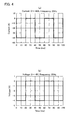
- Fig. 4 is a view showing examples of applied current and voltage waveforms that are outside the scope of the present invention, in which Fig. 4 (a) shows the current waveform, and Fig. 4(b) shows the voltage waveform.
- the duration in which the molten steel path is the cathode is set to 20 ms
- a break time in which the current is not passed is set to 20 ms
- this arrangement is repeated in a time period of electrical waveform cycle of 40 ms.
- the current waveform has the negative-territory current of -40A and the average current of -20A.
- the effective current is 20A, which is equal to the absolute value of the average current.
- Fig. 5 is a view showing other examples of applied current and voltage waveforms that are outside the scope of the present invention, in which Fig. 5(a) shows the current waveform, and Fig. 5(b) shows the voltage waveform.
- Fig. 5 shows current and voltage patterns when the constant negative direct current of -20A is continuously passed through such that the molten steel path becomes the cathode.
- a vertical-bending type continuous casting machine having a casting mold size of 0.3m by 0.4m and a tundish capacity of 15 tons (t) was used in the continuous casting test, and thicknesses of non-metallic inclusions adhering to the inner surface of the submerged entry nozzle 5 after the casting were measured and compared in the following cases: one is the case where the alternating current having the voltage waveform of Fig. 3 was passed through the electrical circuit; another is the case where the direct current having the voltage pattern of Fig. 5 was passed through the electrical circuit; yet another is the case where no electrifying is performed.
- the other electrode 12 made of alumina graphite having a diameter of 100 mm and a length of 800 mm was suspended so as to be immersed in the molten steel 2 from above the tundish 1 by means of the electrode supporting member 15 formed by an insulating element.
- the alumina graphite that constitutes the other electrode 12 has a graphite content of 33 mass % and has electric conductivity.
- the molten steel of Al killed or Si-Al killed plain carbon steel having a chemical composition, in terms of mass %, C: 0.07 to 0.5%, Si: 0.02 to 0.5%, Mn: 0.5 to 1.5%, P: 0.01 to 0.03%, S: 0.01 to 0.08%, and Al: 0.02 to 0.05% was used in the bloom continuous casting test.
- the casting rate was set in the range of 0.6 to 0.7 m/min, and the superheat (temperature difference in which molten steel temperature is subtracted from liquidus temperature) during the casting was set in the range of 20 to 45°C.
- the thickness of the non-metallic inclusions mainly containing alumina and adhering to the inner surface of the submerged entry nozzle 5 was measured by the following method.
- the submerged entry nozzle is cut in a direction perpendicular to the axis of the submerged entry nozzle at a position corresponding to a height of the molten steel surface in the casting mold during the casting, the thickness of the inclusion adhesion in the cut surface (cross-sectional surface) was measured at four points in a circumferential direction, and an average value of the thickness was obtained and regarded as the thickness of the non-metallic inclusion adhesion.
- the inclusions mainly contain white alumina, and the substrate steel was included therein.
- Table 1 shows the condition of applied current voltage and the measurement result of the thickness of the non-metallic inclusion.
- the thickness of non-metallic inclusion adhesion is indicated in terms of relative thickness based on a reference thickness of 10 of the non-metallic inclusion adhesion in Test No. 3 in which the inside of the submerged entry nozzle is not electrified.
- Test No. 2 of the comparative example in which the direct current of Fig. 5 not satisfying the condition defined in the present invention is applied the relative adhesion thickness of the non-metallic inclusions was reduced to 7.5.
- Test No. 2 is not sufficient to exhibit the effect of preventing the inclusion adhesion, although the adhesion thickness is reduced compared with the case of Test No. 3 in which the electrifying is not performed.
- the current or voltage is controlled to electrify between the inner surface of the molten steel path from the upper nozzle of the tundish to the submerged entry nozzle via the sliding gate and the molten steel passing through the inside of the molten steel path such that the polarities alternate in a time period of 1 to 100 ms and such that the molten steel path polarity as being defined by the average current or average voltage becomes the cathode. Therefore, while the generation of the depositions mainly containing alumina is prevented, the adhesion of the inclusions can be suppressed by effectively utilizing the change in wettability between the refractory and the molten steel by electrifying.
- the method of the present invention exhibits the excellent effect of preventing the inclusion adhesion compared with the conventional continuous casting process in which the casting is performed while electrifying, and the method of the present invention can be widely applied as the continuous casting process capable of producing the high-quality cast products under stable operations.
Landscapes
- Engineering & Computer Science (AREA)
- Mechanical Engineering (AREA)
- Continuous Casting (AREA)
- Treatment Of Steel In Its Molten State (AREA)
Abstract
Description
- The present invention relates to a continuous casting process in which the clogging of a molten steel path such as a submerged entry nozzle is prevented. More particularly, the invention relates to a steel continuous casting process, in which an amount of non-metallic inclusions deposited onto an inner surface of the molten steel path is reduced by electrifying between the inner surface of the molten steel path and molten steel passing through the inside of the path, thereby preventing the clogging of the molten steel path.
- In the steel continuous casting, one important challenge is to prevent the clogging of the molten steel path due to adhesion of non-metallic inclusions, typified by alumina (Al2O3), to an inner surface of the molten steel path from a tundish to a submerged entry nozzle. Conventionally, many countermeasures have been proposed in order to prevent the clogging of the molten steel path. Examples of the conventional countermeasures to prevent the clogging of the molten steel path include improvements of quality and shape of materials constituting the molten steel path, prevention of adhesion of depositions by gas purging, and prevention of clogging by applying electrochemical means.
- As to an approach from the standpoint of materials constituting the molten steel path, there is a well known technique, in which a refractory containing neither SiO2 as low-grade oxide nor carbon as a potential CO gas source is provided in the inner surface of the path, and the reaction between the refractory and the molten steel is suppressed to prevent the generation and adhesion of Al2O3 as reaction product. In addition, there is a well known method in which a CaO containing refractory that reacts with Al2O3 to lower a melting point is provided in the inner surface of the molten steel path to wash off Al2O3.
- An effect of the material improvement is limited, or there still remains a problem in that the washed-off coarse inclusions are caught and mingled into the molten steel and taken into cast products.
- As to an approach from the standpoint of the shape improvement, Japanese Patent Application Publication Nos.
05-318057 11-123509 2001-129645 05-318057 2001-129645 11-123509 - The improvement of the shape generally exerts the effect only in cases where a flow rate of the molten steel or a purging amount of inert gas satisfies a specific condition, and it is difficult to prevent the adhesion of the inclusions under broad casting conditions.
- As to the method for purging gas into the nozzle, for example, Japanese Patent Application Publication No.
04-319055 - In these gas purging techniques, an amount of bubbles taken into cast products to form a pinhole therein is increased as the purging amount is increased, resulting in a problem that the quality of cast products is deteriorated.
- As to the countermeasure from the electrochemical standpoint, for example, Japanese Patent Application Publication Nos.
2001-170742 2001-170761 2003-200242 2005-66689 - The improvement technique from the electrochemical standpoint exerts the excellent effect of preventing the inclusion adhesion. However, in the method in which the solid electrolyte is used among the techniques, disadvantageously the solid electrolyte is expensive or has a low resistance to thermal shock. Therefore, it has been difficult for the method to be widely applied to the continuous casting process.
- In view of the above problems, the present invention is attempted, and the task of the present invention is to provide a continuous casting process in which the clogging of the molten steel path from the tundish to the submerged entry nozzle is prevented. Particularly, the invention is applied to a casting method in which a carbon containing refractory such as widely-used alumina graphite is used for the molten steel path, among the casting methods in which the inclusion adhesion is prevented by the above-described electrochemical improvement. An object of the present invention is to provide a steel continuous casting process in which an excellent inclusion adhesion preventing effect is exerted by optimizing the voltage or current waveform to be applied.
- As the casting methods described in Japanese Patent Application Publication Nos.
2003-200242 2005-66689 - (a) A CO gas generating reaction as being one process of dissolution wastage reaction of the refractory can be prevented by electrifying while the refractory constituting the molten steel path is used as a cathode. As a result, the electrifying method has such merit that the CO gas becomes an oxygen source to oxidize Al in the molten steel, thereby preventing the Al2O3 generating reaction.
- (b) However, when electrifying is performed while the refractory is set as the cathode, there arises such demerit that oxygen ion elution simultaneously progresses and the oxygen ion becomes the oxygen source to oxidize Al in the molten steel, thereby generating Al2O3.
- (c) As a result of coexistence of the above merit and demerit, the effect is limited when electrifying only is performed while the refractory is simply used as the cathode. For example, as the voltage or current is increased, the proportion of the demerit is relatively increased and the adhesion of inclusions is rather promoted.
- (d) In spite of the refractory polarity (that is, whether the refractory is set to the cathode or anode) during electrifying, when the voltage or current is increased, wettability between the refractory and the molten steel becomes well by movements of ions or electrons at an interface. As a result, the action on driving out the inclusions in the molten steel toward the refractory side by a repelling force in the molten steel is reduced to decrease the frequencies that the inclusions contact with the inner wall surface of the refractory, so that the inclusions are prevented from adhering to the refractory.
- The present inventors gave further tests and considerations to achieve the present invention in a process of uncovering the method for restraining the demerit of (b) while the merit of (a) and the effect of (d) aremaximallyenjoyed.
- The present invention has been made based on the above findings and understandings, and the gist thereof is summarized in the following steel continuous casting processes (1) to (3).
- (1) A steel continuous casting process in which: a molten steel path from an upper nozzle of a tundish to a submerged entry nozzle through a sliding gate is provided; the whole or part of the molten steel path constitutes one electrode; and electrifying is performed by providing a potential difference between the inner surface of the molten steel path and molten steel passing through the inside of the molten steel path, the process being characterized in that: the other electrode is provided in a portion except for a refractory constituting said one electrode in the tundish to thereby form an electrical circuit between said portion and the molten steel path; the polarity of the molten steel path and the polarity of the other electrode repeatedly alternate between the cathode and the anode in a time period of 1 to 100 ms (millisecond); and electrifying is performed such that the polarity of the molten steel path, which is defined by an average current or an average voltage, is regarded as the cathode while the other electrode becomes the anode, when the time period in which the molten steel path is the cathode while the other electrode being the anode is longer than that of the reversed condition, namely, the other electrode reversely being the cathode while the molten steel path being the anode and/or when an average potential difference during the time period in which the molten steel path is the cathode while the other electrode being the anode is larger than that of the reversed condition, namely, during the time period in which the other electrode is the cathode while the molten steel path being the anode (hereinafter referred to as "a first invention").
- (2) The steel continuous casting process described in the above (1), in which an average current density ranges from 3 to 200 A/m2 (hereinafter referred to as "a second invention").
- (3) The steel continuous casting process described in the above (1) or (2), in which the polarity of one electrode and the polarity of the other electrode change and alternate in a pulse-like steep waveform (hereinafter referred to as "a third invention").
- As used herein, "average potential difference" means a value obtained by time-averaged absolute values of instantaneous values of the potential difference for one cycle of the waveform.
- "An average potential difference during the time period in which the molten steel path is the cathode while the other electrode is the anode is larger than that of the reversed condition, namely, during the time period in which the other electrode is reversely the cathode while the molten steel path being the anode" means that a value obtained by time-averaged absolute values of instantaneous values of the potential difference during the time period in which the molten steel path is the cathode while the other electrode is the anode for the period, is larger than that of the reversed condition, namely, a value obtained by time-averaged absolute values of instantaneous potential difference readings during the time period in which the other electrode is reversely the cathode while the molten steel path being the anode for the period. This is synonymous with the condition "a time period in which the molten steel path is the cathode while the other electrode being the anode is longer than that of the reversed condition, namely, a time period in which the other electrode is reversely the cathode while the molten steel path being the anode" when the voltage waveform is a sine-shaped waveform. However, since this is not always synonymous when the voltage waveform is a pulse-like waveform or a rectangular waveform, "a time period in which the molten steel path is the cathode while the other electrode being the anode is longer than that of the reversed condition, namely, a time period in which the other electrode is the cathode while the molten steel path is the anode" is defined as an independent subject matter.
- "An average current or an average voltage" means a value obtained by time-averaged instantaneous values of the current or voltage for one cycle of the waveform, and "average current density" means a value obtained by time-averaged absolute values of instantaneous current density readings for one cycle of the waveform.
- According to the continuous casting process of the present invention, the current or voltage waveform is controlled to electrify between the inner surface of the molten steel path from the upper nozzle of the tundish to the submerged entry nozzle via the sliding gate and the molten steel passing through the inside of the molten steel path such that the polarities are periodically alternated and such that the time period in which the molten steel path is the cathode is longer than that of the reversed condition, namely, the time period in which the molten steel path reversely is the anode, and/or such that the molten steel path polarity defined by the average current or average voltage is regarded as the cathode. Therefore, the change in wettability by electrifying is effectively utilized while the generation of Al2O3 is prevented, whereby the adhesion of the inclusions can be suppressed. Accordingly, compared with the conventional continuous casting process in which casting is performed with electrifying, the method of the present invention exhibits more excellent effect of preventing the adhesion of the inclusions.
-
-
Fig. 1 is a view schematically showing an example of a configuration of a machine used to perform a continuous casting process according to the present invention. -
Fig. 2 is a view showing examples of current and voltage waveforms to be applied according to the present invention, in whichFig. 2(a) shows the current waveform, andFig. 2(b) shows the voltage waveform. -
Fig. 3 is a view showing other examples of the current and voltage waveforms to be applied according to the present invention, in whichFig. 3 (a) shows the current waveform, andFig. 3(b) shows the voltage waveform. -
Fig. 4 is a view showing examples of applied current and voltage waveforms that are outside the scope of the present invention, in whichFig. 4 (a) shows the current waveform, andFig. 4(b) shows the voltage waveform. -
Fig. 5 is a view showing other examples of applied current and voltage waveforms that are outside the scope of the present invention, in whichFig. 5(a) shows the current waveform, andFig. 5(b) shows the voltage waveform. - As described above, the present invention provides a steel continuous casting process in which a molten steel path from an upper nozzle of a tundish to a submerged entry nozzle is provided, the whole or part of the molten steel path constitutes one electrode and electrifying is performed by providing a potential difference between the inner surface of the molten steel path and molten steel passing through the inside of the molten steel path, characterized in that: the other electrode is provided in a portion except for a refractory constituting said one electrode in the tundish to thereby form an electrical circuit between said portion and the molten steel path; the polarity of the molten steel path and the polarity of the other electrode alternate in a time period of 1 to 100 ms; and electrifying is performed such that the molten steel path polarity, which is defined by an average current or an average voltage, is regarded as the cathode while the other electrode becomes the anode.
-
Fig. 1 is a view schematically showing an example of a configuration of a machine used to perform a continuous casting process according to the present invention. Amolten steel 2 supplied from a ladle (not shown) to a tundish 1 passes through anupper nozzle 3 and asliding gate 4 adjusts a flow rate of themolten steel 2, and thereafter, themolten steel 2 is poured into a casting mold 7 from anozzle outlet port 6 via a submergedentry nozzle 5. Themolten steel 2 forms asolidified shell 8 formed from a contact portion with the casting mold by a heat removing effect of the casting mold 7, and is withdrawn downward to yieldcast products 9. InFig. 1 , thenumeral 10 designates mold powders. - In the method of the present invention, the whole or part of the molten steel path from the
upper nozzle 3 of the tundish to the submergedentry nozzle 5 via thesliding gate 4 constitutes one electrode, and the other electrode is provided in the portion except for theupper nozzle 3 in the tundish 1 and thesliding gate 4. In the example ofFig. 1 , oneelectrode 11 is placed in the submergedentry nozzle 5, theother electrode 12 is placed so as to be submerged into themolten steel 2 from above the tundish 1 by means of anelectrode supporting member 15 formed by an insulating element. The electricity supplied from apower supply 13 is controlled to the desired voltage and current waveform by a voltagecurrent control unit 14, and the electricity is supplied to each electrode throughelectrical wiring 16. - The reason why the present invention is defined as described above and preferred modes will be described below.
- As described above, the first invention is the steel continuous casting process, characterized in that a current or voltage waveform is controlled to electrify between the inner surface of the molten steel path from the upper nozzle of the tundish to the submerged entry nozzle and the molten steel passing through the inside of the molten steel path such that the polarities alternate in a time period of 1 to 100 ms and such that the molten steel path polarity as being defined by the average current or average voltage is regarded as the cathode.
- In the first invention, the alternation between the molten steel path polarity and the other electrode polarity will be described in detail.
- The voltage or current necessary to obtain the merit (a) : "a CO gas generating reaction as being one process of dissolution wastage reaction of the refractory can be prevented by electrifying while the refractory being used as the cathode, thereby preventing the Al2O3 generation caused by the oxidization of Al in the molten steel" is relatively small. Keeping the voltage or current at a small value is also effective to restrains the above demerit (b) to the minimum level.
- On the other hand, in order to obtain the above effect (d), it is necessary to apply high voltage or current as much as possible.
- Therefore, the present inventors have found an electrifying method in which the polarities are repeatedly alternated between the cathode and the anode in a periodical manner and the molten steel path polarity turns to the cathode when the polarity is defined by the average voltage or average current, as a method of suppressing the average voltage or average current at lower level while the high effective voltage or effective current is applied. That is, as described above, the molten steel path polarity can be the cathode by adopting the waveform where a time period in which the molten steel path is the cathode is lengthened and/or the waveform where an average potential difference is increased during the time period in which the molten steel path is the cathode.
- At this point, the time period of alternation between the molten steel path polarity and the other electrode polarity ranges from 1 to 100 ms. When the time period is shorter than 1 ms, the effect (d) of movements of ions or electrons at the interface is not generated sufficiently, and therefore the effect of preventing the inclusion adhesion is not exhibited adequately. On the other hand, when the polarity alternating period is longer than 100 ms, the inclusion adhesion preventing effect is reduced due to the oxygen ion elution described in the above (b). Morepreferably, thepolarityalternatingperiod ranges from 3 to 50 ms.
- The second invention is the steel continuous casting process described in the above (1), in which an average current density ranges from 3 to 200 A/m2. The reason why the average current density preferably ranges from 3 to 200 A/m2 will be described below.
- When the average current density is lower than 3 A/m2, the merit (a) of the effect as suppressing the CO gas generating reaction is reduced. When the average current density exceeds 200 A/m2, the inclusion adhesion preventing effect is lowered due to the demerit (b) of the oxygen ion elution. More preferably, the average current density ranges from not less than 5 A/m2 to less than 100 A/m2.
- The third invention is the steel continuous casting process described in the above (1) or (2), in which the polarity of said one electrode and the polarity of the other electrode change and alternate in a pulse-like steep waveform. The reason why the polarity of the molten steel path from the upper nozzle of the tundish to the submerged entry nozzle and the polarity of the other electrode are preferably changed and alternated in a pulse-like steep waveform in the third invention will be described below.
- When the molten steel path polarity turns from the anode to the cathode, the carriers of electric charges such as free electrons, cations, and oxygen ions start to be mobilized in the refractory or in a slag layer including an antioxidant on the surface of the refractory. At this point, when the voltage or current is changed in a steep waveform, other carriers of electric charges are preferentially moved rather than the oxygen ions having the large ion radii, so that the oxygen ions can be prevented from being mobilized toward the molten steel side. When the molten steel path polarity turns from the cathode to the anode, the change of the steep waveform is not particularly required. However, since it is difficult to selectively change the waveform according to the direction of the polarity change, it is practical to perform the change of the voltage or current in either direction by the pulse-like steep waveform.
- The present invention is similar to the method proposed in Japanese Patent Application Publication No.
2005-66689 2005-66689 - A first basic philosophy of the present invention is to increase the effective current or effective voltage to maximally utilize the effect of movements of ions and the like at the interface. A second basic philosophy of the present invention is that, when the polarity is defined by the average current or average voltage, the molten steel path polarity is set as the cathode, and the average current or average voltage are controlled such that the demerit (b) is restricted while the merit (a) is obtained. A third basic philosophy of the present invention is to increase the effective current to at least three times or five times the average current. As used herein, "affective current" or "effective voltage" means a square root of the time-averaged square of instantaneous current or voltage readings for one cycle of the waveform.
- That is, the present invention essentially differs from any conventional technique in the casting method in which the above first to third basic philosophies can be simultaneously realized.
- The effect of the present invention is expected to be increased with increasing the effective current. However, when the effective current is excessively increased, an electrifying cable becomes too large, and the cable is difficult to handle. Therefore, the practical effective current has an upper limit of about 300A. When an effective current density is excessively small, the effect of the present invention is reduced, and therefore, it is necessary that the effective current density be at least 100 A/m2 or more, more preferably 200 A/m2 or more. It should be noted that the effective current density is higher than the average current density in the present invention.
- In order to confirm the effect of the steel continuous casting process of the present invention, the following test was performed to evaluate the result.
-
Fig. 2 is a view showing examples of current and voltage waveforms to be applied according to the present invention, in whichFig. 2(a) shows the current waveform, andFig. 2(b) shows the voltage waveform. Referring toFig. 2 , an alternating current of the sine-shaped curve having a frequency of 50 Hz, that is, the current maximum of +50A and the current minimum of -50A in one period of electrical waveform cycle of 20 ms is passed through the continuous casting machine shown inFig. 1 while being shifted by 20A toward the negative side such that the molten steel path polarity becomes the cathode. The examples ofFig. 2 are the current and voltage waveforms that satisfy the condition defined in the first invention of the present invention. The electrical circuit of the continuous casting machine had a resistance of 0.1Ω. -
Fig. 2 shows that the average current is -20A and the molten steel path polarity is the cathode. The current waveform has a current peak value of -70A in the negative territory and a current peak value of +30A in the positive territory. The voltage waveform has a voltage peak value of -7V in the negative territory and a voltage peak value of +3V in the positive territory. The average current in the negative territory is -43A and the average current in the positive territory is +20A. The effective current becomes 41A from the above described definition. Accordingly, the effective current becomes about double the absolute value of the average current. -
Fig. 3 is a view showing other examples of the current and voltage waveforms applied according to the present invention, in whichFig. 3(a) shows the current waveform, andFig. 3(b) shows the voltage waveform. Referring toFig. 3 , an alternating current of a rectangular waveform in which the polarities are changed and alternated in the pulse-like steep waveform is passed through the continuous casting machine shown inFig. 1 , and the examples ofFig. 3 is the current and voltage waveforms that satisfy the conditions defined in the first and third inventions. - In
Fig. 3 , the current waveform has the negative-territory current of -100A, and the electrifying duration thereof is 2.2 ms. The current waveform has the positive-territory current of +100A, and the electrifying duration thereof is 1.8 ms. The voltage waveform has the negative-territory voltage of -10V and the positive-territory voltage of +10V. Combining the two durations as above, the time period of electrical waveform cycle becomes 4 ms. The average current is -10A, and the effective current is 100A. Accordingly, the effective current becomes ten times the absolute value of the average current. -
Fig. 4 is a view showing examples of applied current and voltage waveforms that are outside the scope of the present invention, in whichFig. 4 (a) shows the current waveform, andFig. 4(b) shows the voltage waveform. Referring toFig. 4 , the duration in which the molten steel path is the cathode is set to 20 ms, a break time in which the current is not passed is set to 20 ms, and this arrangement is repeated in a time period of electrical waveform cycle of 40 ms. - In
Fig. 4 , the current waveform has the negative-territory current of -40A and the average current of -20A. The effective current is 20A, which is equal to the absolute value of the average current. -
Fig. 5 is a view showing other examples of applied current and voltage waveforms that are outside the scope of the present invention, in whichFig. 5(a) shows the current waveform, andFig. 5(b) shows the voltage waveform.Fig. 5 shows current and voltage patterns when the constant negative direct current of -20A is continuously passed through such that the molten steel path becomes the cathode. - The effect of the present invention was confirmed by applying the continuous casting process of the present invention to a bloom continuous casting in which the continuous casting machine shown in
Fig. 1 was used. - A vertical-bending type continuous casting machine having a casting mold size of 0.3m by 0.4m and a tundish capacity of 15 tons (t) was used in the continuous casting test, and thicknesses of non-metallic inclusions adhering to the inner surface of the submerged
entry nozzle 5 after the casting were measured and compared in the following cases: one is the case where the alternating current having the voltage waveform ofFig. 3 was passed through the electrical circuit; another is the case where the direct current having the voltage pattern ofFig. 5 was passed through the electrical circuit; yet another is the case where no electrifying is performed. - In performing the continuous casting test in which the electric power having the voltage waveforms of
Figs. 3 and5 was applied, theother electrode 12 made of alumina graphite having a diameter of 100 mm and a length of 800 mm was suspended so as to be immersed in themolten steel 2 from above thetundish 1 by means of theelectrode supporting member 15 formed by an insulating element. The alumina graphite that constitutes theother electrode 12 has a graphite content of 33 mass % and has electric conductivity. The submergedentry nozzle 5 comprises a main body made of alumina graphite, and a slag-in outer circumferential portion made of zirconia graphite, wherein the alumina graphite that constitutes the main body has a graphite content of 28 mass % and has electric conductivity. Since the electrifying portion of the submergedentry nozzle 5 had an area of 0.25m2, the average current density became 10A/0.25m2=40A/m2 in the casting test in which the alternating current ofFig. 3 was applied, and the conditions defined in the first and second inventions were satisfied. - The molten steel of Al killed or Si-Al killed plain carbon steel having a chemical composition, in terms of mass %, C: 0.07 to 0.5%, Si: 0.02 to 0.5%, Mn: 0.5 to 1.5%, P: 0.01 to 0.03%, S: 0.01 to 0.08%, and Al: 0.02 to 0.05% was used in the bloom continuous casting test. The casting rate was set in the range of 0.6 to 0.7 m/min, and the superheat (temperature difference in which molten steel temperature is subtracted from liquidus temperature) during the casting was set in the range of 20 to 45°C.
- After the molten steel of about 80 tons was continuously cast per a single submerged entry nozzle on the above-described condition, the thickness of the non-metallic inclusions mainly containing alumina and adhering to the inner surface of the submerged
entry nozzle 5 was measured by the following method. - After the casting, the submerged entry nozzle is cut in a direction perpendicular to the axis of the submerged entry nozzle at a position corresponding to a height of the molten steel surface in the casting mold during the casting, the thickness of the inclusion adhesion in the cut surface (cross-sectional surface) was measured at four points in a circumferential direction, and an average value of the thickness was obtained and regarded as the thickness of the non-metallic inclusion adhesion. The inclusions mainly contain white alumina, and the substrate steel was included therein.
- Table 1 shows the condition of applied current voltage and the measurement result of the thickness of the non-metallic inclusion.
- [Table 1]
Table 1 Test No. 1 2 3 Classification Inventive example Comparative example Comparative example Condition of Applied current voltage Condition of Fig. 3 Condition of Fig. 5 Without electrifying Thickness of non-metallic inclusion adhesion 5.5 7.5 10.0 (reference) - In Table 1, the thickness of non-metallic inclusion adhesion is indicated in terms of relative thickness based on a reference thickness of 10 of the non-metallic inclusion adhesion in Test No. 3 in which the inside of the submerged entry nozzle is not electrified.
- In Test No. 1 of the inventive example in which casting was performed while the alternating current having the current and voltage waveforms of
Fig. 3 satisfying all the conditions defined in the first, second and third inventions was applied, the relative adhesion thickness of the non-metallic inclusions was reduced to 5.5. - On the other hand, in Test No. 2 of the comparative example in which the direct current of
Fig. 5 not satisfying the condition defined in the present invention is applied, the relative adhesion thickness of the non-metallic inclusions was reduced to 7.5. Test No. 2 is not sufficient to exhibit the effect of preventing the inclusion adhesion, although the adhesion thickness is reduced compared with the case of Test No. 3 in which the electrifying is not performed. - According to the continuous casting process of the present invention, the current or voltage is controlled to electrify between the inner surface of the molten steel path from the upper nozzle of the tundish to the submerged entry nozzle via the sliding gate and the molten steel passing through the inside of the molten steel path such that the polarities alternate in a time period of 1 to 100 ms and such that the molten steel path polarity as being defined by the average current or average voltage becomes the cathode. Therefore, while the generation of the depositions mainly containing alumina is prevented, the adhesion of the inclusions can be suppressed by effectively utilizing the change in wettability between the refractory and the molten steel by electrifying.
- Accordingly, the method of the present invention exhibits the excellent effect of preventing the inclusion adhesion compared with the conventional continuous casting process in which the casting is performed while electrifying, and the method of the present invention can be widely applied as the continuous casting process capable of producing the high-quality cast products under stable operations.
Claims (3)
- A steel continuous casting process in which a molten steel path from an upper nozzle of a tundish to a submerged entry nozzle via a sliding gate is provided, the whole or part of the molten steel path constituting one electrode and generating an electric current due to a potential difference provided between the inner surface of the molten steel path and molten steel passing through the inside of the molten steel path,
characterized in that:the other electrode is provided in a portion except for a refractory constituting said one electrode in the tundish to thereby form an electrical circuit between said portion and the molten steel path;the polarity of the molten steel path and the polarity of the other electrode repeatedly alternate between the cathode and the anode in a time period of 1 to 100 ms (millisecond); andelectrifying is performed such that the polarity of the molten steel path, which is defined by an average current or an average voltage, is regarded as the cathode while the other electrode being the anode, when a time period in which the molten steel path is regarded as the cathode while the other electrode being the anode is longer than that of the reversed condition, namely, the time period in which the other electrode reversely is the cathode while the molten steel path being regarded as the anode, and/or when an average potential difference during the time period in which the molten steel path is regarded as the cathode while the other electrode is the anode is larger than that of the reversed condition, namely, an average potential difference during the time period in which the other electrode is the cathode while the molten steel path being regarded as the anode. - The steel continuous casting process according to claim 1, characterized in that an average current density ranges from 3 to 200 A/m2.
- The steel continuous casting process according to claim 1 or 2, characterized in that the polarity of said one electrode and the polarity of the other electrode change and alternate in a pulse-like steep waveform.
Applications Claiming Priority (2)
| Application Number | Priority Date | Filing Date | Title |
|---|---|---|---|
| JP2007014471 | 2007-01-25 | ||
| PCT/JP2007/069231 WO2008090649A1 (en) | 2007-01-25 | 2007-10-02 | Continuous casting method of steel |
Publications (2)
| Publication Number | Publication Date |
|---|---|
| EP2106866A1 true EP2106866A1 (en) | 2009-10-07 |
| EP2106866A4 EP2106866A4 (en) | 2016-10-19 |
Family
ID=39644227
Family Applications (1)
| Application Number | Title | Priority Date | Filing Date |
|---|---|---|---|
| EP07828971.7A Withdrawn EP2106866A4 (en) | 2007-01-25 | 2007-10-02 | PROCESS FOR CONTINUOUS CASTING OF STEEL |
Country Status (5)
| Country | Link |
|---|---|
| EP (1) | EP2106866A4 (en) |
| JP (1) | JP5024296B2 (en) |
| KR (1) | KR101085349B1 (en) |
| CN (1) | CN101583447B (en) |
| WO (1) | WO2008090649A1 (en) |
Cited By (4)
| Publication number | Priority date | Publication date | Assignee | Title |
|---|---|---|---|---|
| CN104128592A (en) * | 2014-08-14 | 2014-11-05 | 昆明理工大学 | Device for refining metal solidification structure with electric current pulses |
| EP3078434A4 (en) * | 2013-12-06 | 2016-10-12 | Posco | Molten metal treating apparatus and molten metal treating method |
| JP2020011261A (en) * | 2018-07-18 | 2020-01-23 | 日本製鉄株式会社 | Apparatus and method for producing fine oxide-dispersed metal lump |
| CN112024864A (en) * | 2020-08-25 | 2020-12-04 | 辽宁科技大学 | A method for removing inclusions in tundish steel by using pulse current |
Families Citing this family (13)
| Publication number | Priority date | Publication date | Assignee | Title |
|---|---|---|---|---|
| JP5316327B2 (en) * | 2009-02-09 | 2013-10-16 | 新日鐵住金株式会社 | Steel continuous casting method |
| JP5869748B2 (en) * | 2009-12-08 | 2016-02-24 | 新日鐵住金株式会社 | Continuous casting method of Al killed steel |
| JP5304716B2 (en) * | 2010-04-13 | 2013-10-02 | 新日鐵住金株式会社 | Continuous casting method of steel containing rare earth metal |
| CN101850406B (en) * | 2010-06-30 | 2012-02-08 | 西安建筑科技大学 | A graphite electrode for applying pulse current to continuous casting tundish |
| JP5360024B2 (en) * | 2010-09-07 | 2013-12-04 | 新日鐵住金株式会社 | Manufacturing method of continuous cast slab |
| JP5768773B2 (en) * | 2012-07-02 | 2015-08-26 | 新日鐵住金株式会社 | Continuous casting method using immersion nozzle |
| JP5768919B2 (en) * | 2014-07-07 | 2015-08-26 | 新日鐵住金株式会社 | Continuous casting method of Al killed steel |
| JP6572658B2 (en) * | 2015-07-28 | 2019-09-11 | 日本製鉄株式会社 | Bubble generating device and bubble generating method in molten metal |
| CN106541123A (en) * | 2015-09-17 | 2017-03-29 | 上海梅山钢铁股份有限公司 | A kind of method for reducing aluminum carbonaceous submersed nozzle inwall dross speed |
| CN107999718B (en) * | 2017-12-07 | 2019-05-31 | 安徽工业大学 | A method of improving micro-alloyed steel continuous casting process castability |
| KR102033631B1 (en) * | 2017-12-22 | 2019-11-08 | 주식회사 포스코 | Flow control Apparatus and Method |
| CN112658241B (en) * | 2020-12-10 | 2022-11-08 | 东北大学 | Method for preventing decarburization and reaction behavior of rare earth steel nozzle by applying interface electric field |
| CN113102744A (en) * | 2021-04-19 | 2021-07-13 | 辽宁科技大学 | A kind of method and operation steps of inhibiting continuous casting nozzle erosion |
Family Cites Families (12)
| Publication number | Priority date | Publication date | Assignee | Title |
|---|---|---|---|---|
| LU85858A1 (en) * | 1985-04-19 | 1986-11-05 | Electro Nite | PROCESS FOR PREVENTING DEPOSITS ON THE WALLS OF METALLURGICAL CONTAINERS AND METALLURGICAL CONTAINER SUITABLE FOR IMPLEMENTING THIS PROCESS |
| JP2891307B2 (en) | 1991-04-16 | 1999-05-17 | 新日本製鐵株式会社 | Steel continuous casting method |
| JPH05318057A (en) | 1992-05-13 | 1993-12-03 | Nippon Steel Corp | Immersion nozzle for continuous casting |
| JP3207793B2 (en) | 1997-10-21 | 2001-09-10 | 品川白煉瓦株式会社 | Immersion nozzle for continuous casting |
| JP2001129645A (en) | 1999-10-29 | 2001-05-15 | Shinagawa Refract Co Ltd | Immersion nozzle for continuous casting and continuous casting method |
| JP4231176B2 (en) | 1999-12-13 | 2009-02-25 | 新日本製鐵株式会社 | Stopper for metallurgy container and / or upper nozzle |
| JP4150142B2 (en) | 1999-12-13 | 2008-09-17 | 新日本製鐵株式会社 | Sliding nozzle of metallurgical container |
| BR0108635A (en) * | 2000-12-25 | 2002-12-10 | Sumitomo Metal Ind | Melting steel supply apparatus for continuous casting, and continuous casting method for the same |
| JP3747848B2 (en) * | 2000-12-25 | 2006-02-22 | 住友金属工業株式会社 | Continuous casting method |
| JP2003200242A (en) | 2001-12-27 | 2003-07-15 | Sumitomo Metal Ind Ltd | Immersion nozzle for continuous casting and continuous casting method for molten steel |
| JP4089556B2 (en) * | 2003-08-28 | 2008-05-28 | 住友金属工業株式会社 | Metal continuous casting method |
| JP4419811B2 (en) * | 2004-11-18 | 2010-02-24 | 住友金属工業株式会社 | Continuous casting method for molten steel |
-
2007
- 2007-10-02 CN CN2007800499094A patent/CN101583447B/en active Active
- 2007-10-02 KR KR1020097014367A patent/KR101085349B1/en active Active
- 2007-10-02 EP EP07828971.7A patent/EP2106866A4/en not_active Withdrawn
- 2007-10-02 JP JP2008554961A patent/JP5024296B2/en active Active
- 2007-10-02 WO PCT/JP2007/069231 patent/WO2008090649A1/en not_active Ceased
Non-Patent Citations (1)
| Title |
|---|
| See references of WO2008090649A1 * |
Cited By (5)
| Publication number | Priority date | Publication date | Assignee | Title |
|---|---|---|---|---|
| EP3078434A4 (en) * | 2013-12-06 | 2016-10-12 | Posco | Molten metal treating apparatus and molten metal treating method |
| US9927177B2 (en) | 2013-12-06 | 2018-03-27 | Posco | Molten steel treatment apparatus and molten steel treatment method |
| CN104128592A (en) * | 2014-08-14 | 2014-11-05 | 昆明理工大学 | Device for refining metal solidification structure with electric current pulses |
| JP2020011261A (en) * | 2018-07-18 | 2020-01-23 | 日本製鉄株式会社 | Apparatus and method for producing fine oxide-dispersed metal lump |
| CN112024864A (en) * | 2020-08-25 | 2020-12-04 | 辽宁科技大学 | A method for removing inclusions in tundish steel by using pulse current |
Also Published As
| Publication number | Publication date |
|---|---|
| CN101583447B (en) | 2011-12-28 |
| CN101583447A (en) | 2009-11-18 |
| EP2106866A4 (en) | 2016-10-19 |
| WO2008090649A1 (en) | 2008-07-31 |
| JP5024296B2 (en) | 2012-09-12 |
| JPWO2008090649A1 (en) | 2010-05-13 |
| KR101085349B1 (en) | 2011-11-23 |
| KR20090095644A (en) | 2009-09-09 |
Similar Documents
| Publication | Publication Date | Title |
|---|---|---|
| KR101085349B1 (en) | Continuous casting method of steel | |
| JP5360024B2 (en) | Manufacturing method of continuous cast slab | |
| JP5316327B2 (en) | Steel continuous casting method | |
| CN108778568B (en) | Nozzle, casting device and casting method | |
| JP5768919B2 (en) | Continuous casting method of Al killed steel | |
| DE3232551A1 (en) | METHOD AND DEVICE FOR TREATING AND REFINING LIQUID METAL ALLOYS BY MEANS OF DC-ARC HEATING | |
| CN112658241A (en) | Method for preventing decarburization and reaction behavior of rare earth steel nozzle by applying interface electric field | |
| JP5768773B2 (en) | Continuous casting method using immersion nozzle | |
| JP5869748B2 (en) | Continuous casting method of Al killed steel | |
| JP6572658B2 (en) | Bubble generating device and bubble generating method in molten metal | |
| CN101176914A (en) | A method for preventing clogging and reducing erosion of continuous casting nozzle of steel casting furnace | |
| JP4231176B2 (en) | Stopper for metallurgy container and / or upper nozzle | |
| JP5803851B2 (en) | Continuous casting method of steel containing rare earth metal | |
| JP2020011261A (en) | Apparatus and method for producing fine oxide-dispersed metal lump | |
| JP7393638B2 (en) | Continuous steel casting method | |
| JP4150142B2 (en) | Sliding nozzle of metallurgical container | |
| US6913066B2 (en) | Method and device for producing ingots or strands of metal by melting electrodes in an electroconductive slag bath | |
| KR20170062204A (en) | Casting apparatus and casting method using the same | |
| JP6167778B2 (en) | Steel continuous casting method | |
| JP2568076B2 (en) | Method for preventing the formation of deposits on the walls of metallurgical vessels and metallurgical vessels suitable for carrying out this method | |
| EP1870182B1 (en) | Process for the casting of molten alloy | |
| JP4844376B2 (en) | Method for continuous casting of molten metal | |
| JP6398673B2 (en) | Bubble generation method in molten metal | |
| KR101760489B1 (en) | Device and method for producing magnesium alloy | |
| RU1524298C (en) | Method of continuous casting of bimetal ingots from aluminium alloys |
Legal Events
| Date | Code | Title | Description |
|---|---|---|---|
| PUAI | Public reference made under article 153(3) epc to a published international application that has entered the european phase |
Free format text: ORIGINAL CODE: 0009012 |
|
| 17P | Request for examination filed |
Effective date: 20090616 |
|
| AK | Designated contracting states |
Kind code of ref document: A1 Designated state(s): AT BE BG CH CY CZ DE DK EE ES FI FR GB GR HU IE IS IT LI LT LU LV MC MT NL PL PT RO SE SI SK TR |
|
| DAX | Request for extension of the european patent (deleted) | ||
| RAP1 | Party data changed (applicant data changed or rights of an application transferred) |
Owner name: NIPPON STEEL & SUMITOMO METAL CORPORATION |
|
| RA4 | Supplementary search report drawn up and despatched (corrected) |
Effective date: 20160920 |
|
| RIC1 | Information provided on ipc code assigned before grant |
Ipc: B22D 11/10 20060101AFI20160909BHEP |
|
| STAA | Information on the status of an ep patent application or granted ep patent |
Free format text: STATUS: EXAMINATION IS IN PROGRESS |
|
| 17Q | First examination report despatched |
Effective date: 20170410 |
|
| RAP1 | Party data changed (applicant data changed or rights of an application transferred) |
Owner name: NIPPON STEEL CORPORATION |
|
| GRAP | Despatch of communication of intention to grant a patent |
Free format text: ORIGINAL CODE: EPIDOSNIGR1 |
|
| STAA | Information on the status of an ep patent application or granted ep patent |
Free format text: STATUS: GRANT OF PATENT IS INTENDED |
|
| GRAJ | Information related to disapproval of communication of intention to grant by the applicant or resumption of examination proceedings by the epo deleted |
Free format text: ORIGINAL CODE: EPIDOSDIGR1 |
|
| GRAP | Despatch of communication of intention to grant a patent |
Free format text: ORIGINAL CODE: EPIDOSNIGR1 |
|
| INTG | Intention to grant announced |
Effective date: 20200420 |
|
| INTG | Intention to grant announced |
Effective date: 20200504 |
|
| STAA | Information on the status of an ep patent application or granted ep patent |
Free format text: STATUS: THE APPLICATION IS DEEMED TO BE WITHDRAWN |
|
| 18D | Application deemed to be withdrawn |
Effective date: 20200915 |