EP2106848A2 - Verfahren und Vorrichtung zur Verpuffungsdruckabschwächung - Google Patents
Verfahren und Vorrichtung zur Verpuffungsdruckabschwächung Download PDFInfo
- Publication number
- EP2106848A2 EP2106848A2 EP09155306A EP09155306A EP2106848A2 EP 2106848 A2 EP2106848 A2 EP 2106848A2 EP 09155306 A EP09155306 A EP 09155306A EP 09155306 A EP09155306 A EP 09155306A EP 2106848 A2 EP2106848 A2 EP 2106848A2
- Authority
- EP
- European Patent Office
- Prior art keywords
- attenuating material
- pressure
- deflagration
- attenuating
- pmax
- Prior art date
- Legal status (The legal status is an assumption and is not a legal conclusion. Google has not performed a legal analysis and makes no representation as to the accuracy of the status listed.)
- Granted
Links
Images








Classifications
-
- B—PERFORMING OPERATIONS; TRANSPORTING
- B01—PHYSICAL OR CHEMICAL PROCESSES OR APPARATUS IN GENERAL
- B01J—CHEMICAL OR PHYSICAL PROCESSES, e.g. CATALYSIS OR COLLOID CHEMISTRY; THEIR RELEVANT APPARATUS
- B01J8/00—Chemical or physical processes in general, conducted in the presence of fluids and solid particles; Apparatus for such processes
- B01J8/02—Chemical or physical processes in general, conducted in the presence of fluids and solid particles; Apparatus for such processes with stationary particles, e.g. in fixed beds
- B01J8/06—Chemical or physical processes in general, conducted in the presence of fluids and solid particles; Apparatus for such processes with stationary particles, e.g. in fixed beds in tube reactors; the solid particles being arranged in tubes
-
- B—PERFORMING OPERATIONS; TRANSPORTING
- B01—PHYSICAL OR CHEMICAL PROCESSES OR APPARATUS IN GENERAL
- B01J—CHEMICAL OR PHYSICAL PROCESSES, e.g. CATALYSIS OR COLLOID CHEMISTRY; THEIR RELEVANT APPARATUS
- B01J19/00—Chemical, physical or physico-chemical processes in general; Their relevant apparatus
- B01J19/0006—Controlling or regulating processes
- B01J19/002—Avoiding undesirable reactions or side-effects, e.g. avoiding explosions, or improving the yield by suppressing side-reactions
-
- F—MECHANICAL ENGINEERING; LIGHTING; HEATING; WEAPONS; BLASTING
- F23—COMBUSTION APPARATUS; COMBUSTION PROCESSES
- F23M—CASINGS, LININGS, WALLS OR DOORS SPECIALLY ADAPTED FOR COMBUSTION CHAMBERS, e.g. FIREBRIDGES; DEVICES FOR DEFLECTING AIR, FLAMES OR COMBUSTION PRODUCTS IN COMBUSTION CHAMBERS; SAFETY ARRANGEMENTS SPECIALLY ADAPTED FOR COMBUSTION APPARATUS; DETAILS OF COMBUSTION CHAMBERS, NOT OTHERWISE PROVIDED FOR
- F23M11/00—Safety arrangements
-
- B—PERFORMING OPERATIONS; TRANSPORTING
- B01—PHYSICAL OR CHEMICAL PROCESSES OR APPARATUS IN GENERAL
- B01J—CHEMICAL OR PHYSICAL PROCESSES, e.g. CATALYSIS OR COLLOID CHEMISTRY; THEIR RELEVANT APPARATUS
- B01J2219/00—Chemical, physical or physico-chemical processes in general; Their relevant apparatus
- B01J2219/00049—Controlling or regulating processes
- B01J2219/00245—Avoiding undesirable reactions or side-effects
- B01J2219/00259—Preventing runaway of the chemical reaction
- B01J2219/00261—Predicting runaway of the chemical reaction
-
- B—PERFORMING OPERATIONS; TRANSPORTING
- B01—PHYSICAL OR CHEMICAL PROCESSES OR APPARATUS IN GENERAL
- B01J—CHEMICAL OR PHYSICAL PROCESSES, e.g. CATALYSIS OR COLLOID CHEMISTRY; THEIR RELEVANT APPARATUS
- B01J2219/00—Chemical, physical or physico-chemical processes in general; Their relevant apparatus
- B01J2219/00049—Controlling or regulating processes
- B01J2219/00245—Avoiding undesirable reactions or side-effects
- B01J2219/00259—Preventing runaway of the chemical reaction
- B01J2219/00263—Preventing explosion of the chemical mixture
Definitions
- the present invention relates to a method and apparatus for controlling, containing and suppressing explosion of combustible gas in a process vessel.
- Combustible materials are often present in the form of liquids, gases, or both, in the reactors, conduits, storage vessels, separations apparatus, etc. of various manufacturing processes, such as those which produce (meth)acrylates, (meth)acrcylate esters, nitriles, and various other materials.
- combustible gas When combustible gas is present in sufficient concentrations, by volume, with oxygen, exposure to an ignition source, such as a spark, a chemical reaction, a hot wire or other hot surface, or even a hot spot (i.e., a localized region of increased temperature in a body of fluid) may initiate localized deflagration in the combustible gas.
- Combustible gases generally deflagrate at concentrations above the lower explosive limit and below the upper explosive limit of the combustible gas.
- Combustible gas may, of course, be comprised of a single kind of gas, but is often a mixture of one or more different gases, the particular composition of which renders the mixture combustible. Where a combustible gas is present, there is always some risk of deflagration because inadvertent ignitions cannot be 100% prevented.
- the deflagration may or may not progress, ultimately, to one or more further damaging events such as detonation or explosion.
- further damaging events such as detonation or explosion.
- such events have the potential to cause severe damage to equipment, as well as serious injury, or even death, to personnel who operate and monitor the equipment.
- the control, containment and suppression of ignition, combustion, deflagration and detonation or explosion of combustible materials are of critical importance to the safe and ongoing operation of many industrial manufacturing and processing operations. While some apparatus and technologies address avoidance of ignition, others attempt to contain, suppress, and extinguish a combustion event which would otherwise develop following inadvertent ignition. See, e.g., Grossel, Stanley S., Ed., Deflagration and Detonation Flame Arresters, AIChE (Center for Chemical Process Safety), New York, New York (2002), Chapter 5, pp.77-138 .
- US Patent No. 3,356,256 discloses the use of heat-dissipating metal netting within fuel storage containers as a means to absorb heat within the container that might otherwise lead to ignition.
- US Patent No. 4,613,054 discloses the use of aluminum foil balls with high thermal conductivity to accomplish the same result. Both approaches seek to employ a heat-sink to prevent sustained combustion from being achieved.
- Fauske See, Fauske, Hans K., Expanded-Metal Networks: A Safety Net to Thwart Gas Explosions, Chemical Engineering Progress, Dec 2001, pp.66-71 ) proposes the use of expanded metal foils as heat sinks within storage tanks to prevent flame-front propagation by removing combustion zone heat-energy. Fauske mimics the design of deflagration arrestors by employing high surface area (400m 2 /m 3 and higher) metal foils with tight passages for flame quenching. In relatively static storage tanks, such tight passages are of little consequence. However, in process vessels, such as reactors, the flow of process fluids through tight passages raises pressure drop across the vessel and consequently increases motive-force energy consumption.
- ⁇ T temperature differential
- process vessels used to handle, react or store combustible gases are operated under conditions of elevated temperatures and/or pressures.
- increased heat and pressure both widens flammability limits (greater range of composition supports combustion) and reduces the incremental energy required to maintain self-sustaining combustion.
- heat-dissipating components such as expanded metal foils
- Propagation of the deflagration pressure wave and flame front in such high temperature and pressure process vessels are simply too fast for heat absorption to occur at a rate that is sufficient to quench the combustion.
- US Patent No. 5,495,893 discloses an apparatus and method to control deflagration of gases, wherein the apparatus includes a combustible substance detector which triggers delivery of a deflagration suppressant into the combustible substance, by a liquid atomizing device for controlling the size of the liquid suppressant droplets.
- the disclosure of this patent states that deflagration can be effectively suppressed by heat absorption, such as by utilizing a fine mist liquid stream (i.e., the deflagration suppressant) that can be rapidly vaporized to quickly remove the heat by which a deflagration propagates.
- This solution is based on the understanding that, in a deflagration, the combustion of a combustible gas initiates a chemical reaction that propagates outward by transferring heat and/or free radicals to adjacent molecules of the combustible gas.
- the transfer of heat and/or free radicals ignites the adjacent molecules and, in this manner, the deflagration propagates or expands outward through the combustible gas.
- US Patent No. 6,540,029 discloses a deflagration suppression and explosion isolation system which has the goal of suppressing the deflagration stage of an explosion and preventing deflagration phenomena originating in a containment structure from propagating into an associated conduit and then transitioning into detonation phenomena in the conduit.
- the system described in this patent includes a pressure detector for detecting a rapid rise of pressure, which is indicative of an incipient explosion, and a suppressant device which directs a fire suppression agent into the combustible gases, as well as a gate valve assembly which closes in tandem with release of the suppressant agent to redirect the flame and combustion generated pressures.
- a pressure detector for detecting a rapid rise of pressure, which is indicative of an incipient explosion
- a suppressant device which directs a fire suppression agent into the combustible gases
- a gate valve assembly which closes in tandem with release of the suppressant agent to redirect the flame and combustion generated pressures.
- 6,540,029 operates to introduce an additional material, a suppressant agent, into the combustible gas for absorption of heat which otherwise facilitates propagation of the deflagration and its transition to detonation.
- a pressure wave and a flame front are generated at the point of ignition and propagate outward in all directions therefrom, with the pressure wave traveling faster than the flame front.
- obstacles and bends in a pipe or conduit containing the combustible gas will increase turbulence (i.e., mixing) which, in turn, accelerates the transition from deflagration to detonation.
- turbulence i.e., mixing
- US Patent No. 6,932,950 is an attempt to minimize or eliminate secondary reactions, including but not limited to ignition and deflagration, which have greater risk of occurring at the inlet side of a tubular reactor where the feed gas mixture is a combustible gas coming in contact with the hot spots proximate to the inlet tube-sheet of the reactor.
- This patent discusses the previously known practices of placing a layer of ceramic materials, or wire mesh, in the inlet chamber, adjacent to the inlet tube sheet on the inlet gas side, but not filling more than about 20% of the chamber's volume, to create a barrier between the incoming feed gas and the hot tube-sheet.
- a device for physically diverting the flame front of a deflagration event is described in US Patent No. 7,000,630 , wherein a flame front diverter directs the high-speed pressure wave towards a bi-directional rupturable disc causing the rupturable disc to open thus creating an aspiration effect on the opposite bi-directional rupturable disc, which creates an escape path for the pressure wave and flame front, as well as drawing in fresh air as a diluent.
- the flame front diverter described in this patent is designed to prevent a deflagration from propagating from one vessel to another.
- the present invention provides a method for attenuating deflagration pressure produced by combustion of combustible gas in a defined region of a process vessel under known operating conditions comprising initial feed gas composition, temperature and pressure, wherein a peak pressure is reached in the defined region after ignition.
- the method generally comprises selecting and placing attenuating material in the defined region of the process vessel, wherein the selected attenuating material maintains its physical shape under the operating conditions and has a plurality of components, all of which have a geometry and an effective diameter.
- the attenuating material should occupy at least 20% of the defined region of the process vessel.
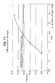
- the first step of the inventive method is determining the maximum effective diameter of components of the attenuating material which is suitable for use in the defined region of the process vessel by developing empirical data comprising associated pairs of peak deflagration pressures and deflagration mixing factors, which demonstrates a linear relationship between a plurality of attenuating materials, at least one of which has components with an effective diameter which differs from the effective diameters of the components of the other attenuating materials, and the peak pressures reached after ignition of combustible gas having the same composition as the initial feed gas composition.
- steps are followed by linearizing the empirical data comprising associated pairs of peak deflagration pressures and deflagration mixing factors ([Pmax(0), DMF(0)]; [Pmax(1) DMF(1)], [Pmax(2), DMF(2)], .. [Pmax(n), DMF(n)]) by determining the value of variables M and B based on the following mathematical relationship: Pmax(
- a suitable attenuating material is selected.
- a suitable attenuating material will have an effective diameter Ds less than or equal to the calculated maximum effective diameter (Ds(a)) for the particular process vessel and placing the selected attenuating material in the defined region of the process vessel.
- the attenuating materials may be simply poured into, or manually arranged in, the defined region of the process vessel, depending on whether the components of the attenuating material are self-ordering, such that void spaces and open pathways between the components are minimized.
- the step of empirically determining the peak deflagration pressure (Pmax(0)) may comprise: (a) igniting the combustible gas in the test sphere, which is otherwise empty, under the pressure and temperature of the predetermined operating conditions; and then (b) measuring the highest pressure (Pmax(0)) reached in the test sphere, after ignition.
- the step of empirically determining at least a first and a second peak deflagration pressure (Pmax(1), Pmax(2)) comprises: (a) igniting combustible gas in the test sphere, after filling it with the first selected attenuating material, under the pressure and temperature of the predetermined operating conditions; (b) measuring the highest pressure (Pmax(1)) reached in the test sphere filled with the first selected attenuating material, after ignition; (c) igniting combustible gas in the test sphere, after filling it with the second selected attenuating material, under the pressure and temperature of the predetermined operating conditions; and (d) measuring the highest pressure (Pmax(2)) reached in the test sphere filled with the second selected attenuating material, after ignition.
- the combustible gas comprises hydrocarbons and oxygen and the process vessel may be a shell and tube reactor which is operating under flowing conditions.
- the present invention also provides a tubular reactor adapted for attenuation of deflagration pressure resulting from combustion of combustible gas therein.
- the inventive tubular reactor comprises attenuating material having a plurality of components, all of which have a geometry and which are placed such that void spaces and open pathways between the components are minimized, wherein the attenuating material occupies at least 20% of at least one of the defined inlet region and the defined outlet regions of the process vessel.
- (DMF(a)) is the deflagration mixing factor associated with the attenuating material and which is determined empirically by the method of the present invention described above.
- R(v) is the radius of whichever defined inlet or outlet region is occupied by the attenuating material.
- the present invention further provides a method for performing gas phase reactions safely under flammable operating conditions, which comprise a gas feed composition, temperature and pressure.
- This method involves: (A) providing a reaction vessel having a defined region through which said gas feed composition passes, said defined region being at least 20% by volume occupied by at least one attenuating material which maintains its physical shape under the flammable operating conditions; (B) providing one or more gaseous materials comprising a hydrocarbon, an oxygen-containing gas and, optionally, an inert material, to said reaction vessel to form said gaseous feed composition which passes through said defined region; and (C ) subjecting said gaseous feed composition to one or more reactions in the reaction vessel, at a temperature and pressure under which said gaseous feed composition is flammable.
- the attenuating material may be selected according to the method for attenuating deflagration pressure produced by combustion of combustible gas described above.
- the hydrocarbon comprises propylene which is subjected to oxidation in a reaction vessel having attenuating materials comprising crimped wire mesh cylinders and crimped wire mesh polyhedrons.
- the gaseous materials further comprise ammonia
- the hydrocarbon comprises methane
- the gas phase reactions comprise ammoxidation of the methane
- the attenuating materials comprise ceramic foam polyhedrons.
- the method of the present invention is suitable for attenuating deflagration pressure produced by combustion of combustible gas in a defined region of a process vessel.
- the method involves selecting and placing attenuating material in the defined region to deflect and fragment the pressure wave associated with the deflagration.
- a “process vessel” means any apparatus that is used in connection with the storage, transport, reaction, manufacture, handling, or other manipulation of combustible substances.
- a “defined region,” as this term is used herein, is the designated area in a process vessel to be protected from the effects of a deflagration.
- the defined region is typically an enclosed area containing a combustible gas or an area in the process vessel within which the risk of a deflagration is greatest.
- the location, geometry and volume of the defined region will vary depending upon the application and process vessel.
- volume-fill refers to the apparent volume occupied by attenuating material in a defined region and is equal to the combined volume actually occupied by the attenuating material components and the interstitial void spaces between those components.
- Combustible gases are gases which are present in sufficient compositions and concentrations, by volume, with oxygen, and whose exposure to an ignition source, such as a spark, a chemical reaction, a hot wire or other hot surface, or even a hot spot (i.e., a localized region of increased temperature in a body of fluid) may initiate localized deflagration in the combustible gas.
- Combustible gas may, of course, be comprised of a single species of gas, such as hydrogen, butane, propylene, etc., but is often a mixture of one or more different gases, the particular composition of which renders the mixture combustible.
- a spherical flame front and a spherical pressure wave are formed by the local combustion of the combustible gas at the ignition source. Both the pressure wave and flame front tend to propagate radially, in all directions, outward and away from the ignition point, into the unaffected portions of the combustible gas. It has been long understood that propagation of the flame front involves heat transfer and proceeds much slower than propagation of the pressure wave, which travels at the speed of sound. This stage of an incipient explosion is generally referred to as a deflagration, i.e., when the pressure wave and flame front are traveling separately, with the pressure wave in advance.
- a free radical is any reactive group of atoms containing unpaired electrons, such as OH, H, and CH 3 .
- the energy of the pressure wave may compress uncombusted portions of the combustible gas ahead of the pressure wave, reducing the thermal energy demand needed to sustain combustion in those portions of combustible gas, thereby facilitating further combustion, accelerating the progression of the flame front, and reinforcing the advancing pressure wave.
- This strengthening of the pressure wave continues up to the point where the pressure wave alone is strong enough to initiate the combustion reaction, thereby initiating the detonation stage.
- the detonation wave will propagate into the compressed combustible gas and catch up to the foremost pressure wave, becoming a stable detonation with a constant velocity.
- a stable detonation wave consists of a pressure wave closely coupled with a flame front such that the energy released by the flame front supports the pressure wave.
- the flame front When deflagration occurs in a pipe or conduit, in which materials tend to travel axially, and the flame front reaches the wall of the pipe or conduit, it changes from spherical form to an essentially planar front. As the planar flame front continues to propagate down the length of the pipe, it begins to elongate and the surface of the flame increases. As the surface area increases, the burning rate increases and as a result, the flame propagation velocity increases. In other words, the propagating flame front may rapidly transition from an initial deflagration state to a detonation state within a conduit.
- the size of the molecules of the combustible material affects the overall explosion phenomena, as does the diameter of the conduit or vessel through which the products of combustion are flowing.
- pipes of larger diameter provide smaller heat sinks than smaller diameter pipes or conduits.
- the longitudinal configuration of piping or conduits also affects the propagation of the flame front and pressure wave. It is known in the art that obstacles and bends in the pipe or conduit can increase turbulence which in turn will tend to increase flame surface area, which leads to enlargement of the flame front and causes faster transition to detonation.
- FIG 8 a simplified explosion diagram which is typical for combustible gas mixtures is shown.
- each such explosion diagram would be specific to a particular composition of combustible gas.
- Such diagrams are well-known in the technical literature, such as discussed in, for example, " Explosions” W. Bartknecht, Springer-Verlag, New York, 1981 (in particular, see Chapter 2, Explosions in Closed Vessels ).
- Standardized testing methodologies have been developed to collect the data needed to produce such diagrams (see for example European Standards DIN EN 13673-1 and DIN EN 13673-2, September 2003). These methodologies generally require that the combustible gas mixture to be tested is initially held in a static condition, within a sealed, adiabatic, and otherwise empty (e.g., free from fill material) testing sphere.
- the diagram of Figure 8 illustrates the typical progression of the deflagration pressure (or "explosion pressure") event in a volume of combustible gas as a function of the elapsed time relative to the moment when the combustible gas is ignited.
- the diagram generally comprises three sequential stages.
- the gas mixture In the first stage, prior to ignition, the gas mixture exists in a static condition at a constant initial pressure (P initial ) and initial temperature.
- time interval, ⁇ t of this transitional state is on the order of only about 100 to 300 microseconds in duration.
- heat transfer sufficient to dampen or slow the deflagration event would require significantly more time, such as on the order of about 500 to 1000 microseconds (i.e., 0.5 to 1.0 seconds).
- the pressure within the test sphere declines over time interval ⁇ T until a lower, "steady-state" pressure, P final , is reached.
- P final steady-state pressure
- the time interval, ⁇ T, necessary to reach P final is on the order of 1000 microseconds or more in duration.
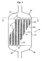
- Figure 1 a schematic, partially cut-away elevational side view is provided of a process vessel to which the method of the present invention may suitably be applied.
- Figure 1 shows a partially cut-away elevational side view of a tubular reactor 10 suitable for catalytic gas phase reactions.
- the tubular reactor 10 has a plurality of tubes 12a, 12b, 12c, 12d, each of which extends between a first perforated plate 14 and a second perforated plate 16, and contains solid materials S, such as one or more types of catalyst and inert materials.
- the plurality of tubes 12a, 12b, 12c, 12d, as well as the first and second perforated plates 14, 16, are enclosed in a shell 18 which forms a region for circulation of heat transfer fluid (not shown per se) around the plurality of tubes 12a, 12b, 12c, 12d for temperature control purposes.
- a flanged cap or "reactor head” 24, is sealingly affixed to the perimeter of the reactor 10 proximate the first tube sheet 14, to form a defined inlet region 20 in fluid communication with the reactor tubes 12a, 12b, 12c, 12d, for allowing reactants (not shown) and other fluids to flow therethrough.
- another flanged cap, or “reactor head” 26 is sealingly affixed to the perimeter of the reactor 10 proximate the second tube sheet 16, to form a defined outlet region 22, which is also in fluid communication with the reactor tubes 12a, 12b, 12c, 12d for allowing reactants, products and other fluids (not shown) to flow therethrough.
- one or more chemical reactions occur, such as, for example, oxidation, during operation of the tubular reactor 10 under flowing conditions.
- monitoring instrumentation may be positioned in the defined region of the process vessel for detection of combustion, local temperature increase, or local pressure increase, such that adjustments to operating conditions may be made, including but not limited to troubleshooting, reduction in operating rates, or shut down of process.
- monitoring instrumentation may include one or more of thermocouples, pressure transducers, fire eyes, and gas composition analyzers and may optionally be connected to distributed process control systems in order to initiate an automated response.
- the monitoring instrumentation (not shown) may be incorporated into safety interlock logic systems along with other process calculations and measurements, such as, for example, flammability calculations or reactor feed stream flow rates.
- redundant monitoring devices may be used to enhance reliability of the monitoring system. If redundant devices are used, they may optionally be configured as part of a computerized voting-logic system, in which two or more measurements must simultaneously register an abnormal condition before automated action is initiated.
- a defined inlet region (inlet head) of a down-flow tubular oxidation reactor contains ceramic sphere components and at least ten multi-point thermocouple assemblies, each of which has about 10 measurement points per assembly.
- Each thermocouple assembly is inserted through sealable openings in the top portion of the (inlet) reactor head, manually positioned by bending to form a predetermined series of evenly-spaced, concentric circles, and then clipped to pre-existing anchoring brackets on the inlet tube sheet.
- a defined inlet region of an up-flow tubular oxidation reactor contains wire mesh cylinder components and at least six "K"-type multi-point thermocouple assemblies with 316 stainless steel sheaths (commercially available from Gayesco of Pasadena, Texas, USA).
- the multi-point thermocouple assemblies of this embodiment are inserted through SWAGELOK packing glands (commercially available from Swagelok Company of Solon, Ohio, USA) which are mounted onto the sidewall of the inlet reactor head, manually positioned by bending to lay proximate to a predetermined distribution of measurement locations, and then affixed at multiple locations along their length to the mesh cylinders, using short lengths of wire.
- samples of the combustible gas feed mixture within the defined inlet region (inlet head) of an oxidation reactor are continuously analyzed by gas chromatograph to detect an increase in the concentration of combustion products, such as, for example, carbon dioxide, carbon monoxide, and water or a decrease in the concentration of combustible hydrocarbons.
- the defined inlet region (inlet head) of an oxygen-enriched hydrogen cyanide reactor comprises 100% volume-fill of 40ppi reticulated ceramic foam and also contains at least two fast-acting pressure transducers (suitable models are commercially available from Kulite Semiconductor Products of New Jersey, USA) in order to detect possible deflagrations within the defined inlet region, and to automatically initiate shutdown of the reaction system via the distributed process control system in the event a deflagration is detected.
- the above described embodiments of the present invention incorporating monitoring instrumentation are but a few examples and are not intended to describe the full scope of possible configurations that may be utilized in accordance with the present invention.
- the selection and specification of appropriate monitoring instrumentation and associated process controls, safety systems, and interlock logic systems will be within the ability of one of ordinary skill in chemical process design and instrumentation, given the benefit of the present disclosure.
- Figure 2 shows a cross-sectional schematic top plan view of the defined inlet region 20 of the tubular reactor 10 of Figure 1 , taken along line A-A and looking in the direction of the arrows.
- the perforated plate 14 and the plurality of tubes 12a, 12b, 12c, 12d are visible in this view. It is in this defined inlet region that the reactants and other materials fed to the tubular reactor 10 all come into contact with one another prior to entering the tubes 12a, 12b, 12c, 12d and contacting the catalyst materials S therein to commence one or more chemical reactions within the tubes 12a, 12b, 12c, 12d.
- combustible gas may be present in the defined inlet region 20, which is susceptible to inadvertent ignition from any number of sources including, but not limited to, hot spots generated proximate to the perforated plate 14 and sparks generated by friction or contact with other apparatus present in the defined inlet region 20. As discussed hereinabove, such ignition may become a deflagration event, which may, in turn, propagate until it transitions to detonation or explosion.
- deflection and fragmenting of the deflagration pressure wave may slow propagation of the pressure wave and lower the maximum pressure attained by the deflagration sufficiently to quench the overall deflagration event and prevent transition to detonation and reduce the peak pressure (Pmax) achieved.
- successful deflection and fragmentation of the deflagration pressure wave may be achieved by selecting and placing suitable attenuating materials in a defined region wherein combustion and deflagration are likely to occur, such as in the defined inlet region 20 of the tubular reactor 10.
- suitable attenuating materials means attenuating materials selected based on their geometry, which includes both size and shape, relative to the size and shape of the defined region.
- Figure 3A is a schematic cross-sectional elevational side view of the empty defined inlet region 20, i.e., without any attenuating materials placed therein, which correlates to attenuating materials occupying 0% of the volume of the defined inlet region 20.
- the defined inlet region 20 is shown bounded by the inlet tube sheet 14 and the reactor head 24.
- Figure 3B shows one embodiment of the present invention wherein the defined inlet region 20 of Figure 3A contains attenuating material which comprises ceramic sphere components 28 and provides a volume-fill of at least 20% by volume of the defined inlet region 20.
- the defined inlet region 20 is located at the top of the process vessel and the process vessel is a tubular reactor with parallel vertical tubes, it is advisable to install a barrier, such as a ceramic mesh or wire screen sheet 30, across the cross-sectional area (see, e.g., Figure 2 ) of the defined inlet region 20 to prevent the components 28 of the attenuating material from entering the tubes 12a, 12b, 12c, 12d through the perforated tube sheet 14 (see, e.g., Figure 1 ).
- a barrier such as a ceramic mesh or wire screen sheet 30 across the cross-sectional area (see, e.g., Figure 2 ) of the defined inlet region 20 to prevent the components 28 of the attenuating material from entering the tubes 12a, 12b, 12c, 12d through the perforated tube sheet 14 (see, e.g., Figure 1 ).
- barrier 30 is especially beneficial because it allows an empty space, or "void region,” to be maintained in the uppermost section of each of the tubes 12a, 12b, 12c, 12d, where the tube ends pass through the first tube sheet 14. Because of the typically large thickness of the tube sheets 14, 16 in such tubular reactors used for oxidation reactions, there is limited cooling in this uppermost section of each tube. Thus, if this region contained attenuating material, oxidation catalyst, or even inert diluent materials, it would be subject to overheating which may, ultimately, cause failure of the welded connection between the tube and tube sheet 14.
- cooling salt typically comprising nitrates and nitrites (e.g., HITEC salt commercially available from DuPont of Wilmington, Delaware, USA) into the defined inlet region 20, and the subsequent decomposition reactions that occur, will culminate in the undesireable autoignition of the propylene oxidation reactor feed gas.
- a layer of 50-millimeter ("mm") (2-inch) thick, (40 pores per inch (“ppi")) reticulated ceramic foam tiles are placed directly on the inlet tube sheet of a downflow propylene oxidation tubular reactor to form a continuous barrier covering the total cross sectional area of the tube sheet, preventing any of the attenuating material from falling into the ends of the tubes.
- a void region i.e., empty of any materials, and which is equivalent in length to the thickness of the reactor inlet tube sheet, is therefore maintained in the upper tube ends of each reactor tube, such that overheating of the welded connections between the tubes and tube sheet is avoided.
- Attenuating material comprising 13 mm (1/2-inch) DENSTONE 2000 support spheres (commercially available from Saint-Gobain Norpro of Stow, Ohio, USA, formerly known as and now merged with Norton Chemical Process Products Corp.) are then placed in the defined inlet region, on top of this barrier, to attenuate deflagration pressure in accordance with the present invention.
- the reticulated ceramic foam tiles may be considered part of the attenuating material, along with the DENSTONE spheres.
- the attenuating material in this case, the ceramic foam and the spheres, should occupy at least 20%, for example, at least 25%, or even at least 30% or at least 50% of the total volume of the defined inlet region 20, wherein the volume occupied by the attenuating material is the sum of the volume of the components of the attenuating material and the volumes of the void spaces therebetween.
- an amount of attenuating material is placed in the defined region which provides at least 20% volume-fill in the defined region.
- Axial mixing is mixing that increases turbulence in the axial direction, which is the direction in which the pressure wave and flame front are propagating
- lateral mixing is mixing that increases turbulence of the combustible gas in directions other than axially, for example, without limitation, substantially perpendicular to the axial direction. It has been found that such lateral mixing is desirably increased as solid or tortuously porous attenuating materials that have smaller effective diameters are used, however, this preference for smaller materials is limited somewhat by the need to avoid too great a pressure drop in the throughput of reactants which occurs when very small materials are used. For example, sand may provide excellent attenuating and fragmentation of a pressure wave, but it will also cause an enormous and generally unacceptable pressure drop during normal operation of the reactor and, therefore, would not typically be a good choice as the only attenuating material.
- the material of construction of the attenuating material components is less important than its geometry with respect to the attenuation of maximum deflagration pressure achieved after ignition, Pmax.
- geometries have proved to be significantly more effective than others, for example, geometries that present minimal axial pathways through which combustible gases may pass (e.g., solid spheres), or present more tortuous and shorter axial pathways (reticulated foam, tightly rolled wire mesh material), tend to deflect and fragment deflagration pressure waves better than materials having geometries that present open, extended axial pathways when placed into the defined region containing the combustible gas (e.g., rings, hollow cylinders).
- minimizing axial pathways may be achieved, at least in part, by maximizing the packing factor and/or minimizing the volumetric (interstitial) void space between components of the attenuating material placed in the defined region of a process vessel, which is further known to depend upon the particular geometry (size and shape) of the attenuating material and its components.
- the determination and calculation of packing factors and volumetric void space is well within the skill of persons having ordinary skill in the art with reference to basic texts and treatises. For example, bulk density & void fraction data can be measured empirically (fill a fixed volume with material, determine the mass of the material used, and then divide by the density of a single particle to ascertain how much free space there is included on a % basis).
- the degree of success achieved by a particular type of attenuating material, having a selected geometry and material of construction, is assessed, at least in part, by its ability to decrease the maximum pressure (Pmax) attained by a deflagration pressure wave in combustible gas in an otherwise empty defined region, as compared to the maximum pressure attained in the combustible gas under the same operating conditions in the same defined region when filled with the attenuating material.
- Pmax maximum pressure
- Example 1 hereinbelow provides data showing that 2-inch (50.8mm) Pall rings placed in a defined region surprisingly increased, rather than decreased, the maximum deflagration pressure attained by combustible gas ignited in the defined region, as compared to an empty defined region.
- Example 1 The results of the experiments described in Example 1 also demonstrate that layers of crimped wire mesh in the defined region, which appear to have provided a significantly larger total surface area, consistently decrease the maximum deflagration pressure after ignition of the combustible gas, but, notably, fail to extinguish combustion via heat removal mechanisms.
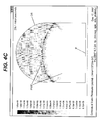
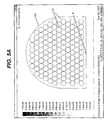
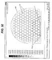
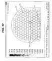
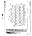
- Figures 4A-4C and 5A-5J are each a series of graphical images produced by computer model software, showing the progression of a deflagration Pressure Wave Front (PWF), at various time intervals not exceeding a total elapsed time of 200 microseconds, beginning with ignition at a single point (P) in a defined region (DR).
- the defined region is the dome-shaped inlet region of a tubular reactor vessel (such as was discussed above in connection with Figures 1-3 ).
- the images of Figures 4A-4C and 5A-5J display the defined region from a side view, similar to that provided in Figures 3A & B .
- the shading of the pressure wave varies with pressure such that the darker grey color of a portion of a pressure wave indicates a higher localized pressure than in other portions of the pressure wave.
- the leading edge (PWF) of the deflagration pressure wave front is a dark shade of grey compared to the slightly lighter, but not particularly light, shade of grey seen behind the leading front and closer to the point of ignition (P).
- Figures 4A-4C show the progression of a deflagration pressure wave front (PWF) from the point of ignition (P) in the defined region (DR) containing no attenuating materials.
- PWF deflagration pressure wave front
- the deflagration pressure wave front propagates through the empty vessel, steadily in all directions away from the ignition point, as shown in Figures 4A-4C , by the semicircular leading edge of the PWF.
- Figures 5A-5J show the progression of a deflagration (PWF) from the point of ignition (P) in the defined region (DR), but the defined region (DR) now contains attenuating material comprising ceramic spheres (CS).
- the deflagration pressure wave front still proceeds outwardly in all directions from the point of ignition, but that the smooth, continuous, semicircular wave front is deflected and fragmented when it contacts the attenuating material. Even though a maximum deflagration pressure (Pmax) is still achieved when attenuating material is used, the Pmax reached is less than the Pmax reached by the deflagration in the empty test vessel. It can also be seen that the propagation of the deflagration pressure wave front takes very little time - on the order of a couple of hundred microseconds. This indicates that lateral deflection of the deflagration pressure wave by some kind of attenuating material comprising solid components decreases the maximum pressure ultimately reached by the pressure wave.
- the "effective diameter" is a quantifiable characteristic of attenuating material having a plurality of components, such as ceramic spheres, or Pall rings, etc., which was developed by the inventors to quantify the cross-sectional profile of each component of the attenuating material available for impeding the propagation of the pressure wave front during deflagration.
- the "effective diameter,” as used herein, is analogous to the "hydraulic diameter” concept which is known by persons of ordinary skill in the art of flame arrestor design.
- the concept of hydraulic diameter provides means to quantify the effect of geometry and surface area of non-circular pipes and conduits with respect to the removal of thermal energy from fluids flowing through them.
- the concept of "effective diameter” has been developed to provide analogous quantification of the effects of geometry of attenuating material having non-spherical components on the propagation of a pressure wave front therethrough, as compared to generally spherical components, which present a consistently circular cross-sectional profile as an impediment to pressure wave propagation.
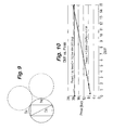
- Mathematical calculation of the inscribed volume ratio can be readily accomplished by those of ordinary skill in geometry and trigonometry.
- the "effective diameter" of the components of attenuating material means the average diameter of a sphere in which a single average component is inscribed. "Equal effective diameter” means an effective diameter that is numerically the same to within a measurement tolerance of about +/- 5%, for example, or even 10% or 20%.
- Applicants have discovered that both the geometry and effective diameter of the individual pressure attenuating components (e.g., component geometry), as well as the ordering or packing of these components relative to one other can affect the degree of pressure attenuation achieved in a particular process vessel. Generally speaking, the smaller the effective diameter of the components, the greater the pressure attenuation. Additionally, applicants have found that multiple layers of the components of attenuating material produce a greater degree of deflagration pressure attenuation than a single layer of components, and that the greatest attenuation is possible when the majority of the defined area of the process vessel is filled with attenuating material.
- Channeling means development of relatively unobstructed flow of fluid along the path in a configuration of obstacles or equipment which presents at least semi-contiguous passageways through which the fluid can easily and steadily flow, rather than being deflected or hindered.
- Attenuating materials whose components tend to be self-ordering enable the efficient filling of a vessel by simply pouring or dumping of attenuating material into the defined area of the process vessel.
- Attenuating material comprising generally spherical components of equal effective diameter approximates this idealsphere behavior quite well, with particles that have higher inscribed volume ratios most closely approximating this ideal sphere behavior.
- Attenuating material comprising generally spherical particles, of equal effective diameter
- High pressure drop requires increased pressurization of the gas fed into the process vessel (through, for example, the use of a gas compression system), which is costly.
- increased pressurization of the gas feeds has an adverse effect on the flammability limits and autoignition temperature of the system.
- the objective of minimizing pressure drop is in direct opposition to the objective of maximizing pressure attenuation through the use of small particles (as stated above) and it becomes difficult in practice to rectify this situation without performing a prohibitively large number of expensive laboratory tests.
- the DMF provides a basis for identifying the maximum effective diameter that may be used in a given process vessel in order to obtain deflagration pressure attenuation. Without such a method, it would be necessary to construct full scale testing systems in the laboratory in order to obtain this information. Given that many process vessels may be 20 or more feet (6.1 or more meters) in diameter, such a testing approach is impractical. In our example, solid, hollow ceramic balls of 3.6 inches (9.14 centimeters) diameter can be effectively used in a commercial vessel having a diameter of 22 feet (6.7 meters), based on successful testing of 1 ⁇ 4-inch DENSTONE spheres in the 10 liter laboratory testing vessel.
- the method of the present invention has been developed for use with attenuating materials having generally spherical components of equal effective diameter. We believe that the method most accurately predicts pressure attenuating behavior when the inscribed volume ratio is high and, therefore, it is preferred to use attenuating materials having components with an inscribed volume ratio of > 0.3 (DENSTONE cylinder), more preferably, components with an inscribed volume ratio of > 0.6 (cube), or even components with an inscribed volume ratio of > 0.9 (DENSTONE spheres).
- the method may be effectively used with attenuating material comprising reticulated ceramic foam components, wherein the diameter of the average pore size is substituted for the effective diameter of a spherical component.
- ceramic foam with a nominal porosity of 20 pores per inch (“ppi") would have an effective diameter of 1.27mm (25.4mm / 20).
- the method will also be reasonably effective at predicting the behavior of a attenuating material comprising a mixture of two generally spherical components, such as, for example, DENSTONE spheres and DENSTONE cylinders. If the effective diameters of the two component types are the same, the mixture will approximate the performance of a single component-type attenuating material, and the accuracy of that prediction will be best at smaller effective diameters.
- the ratio of the component diameters (D large /D small ) be at least 100, for example, at least 1000. Differences in diameters can negatively impact the ordering of the component layers, creating channel-like voids at the interface region between two adjacent (different sized) particles, which of course diminishes the local pressure attenuation in that region. As the size difference increases, the large diameter component begins to have less detrimental effect on the pressure attenuation, because the smaller particles can more easily pack into the interface regions between the large diameter particles.
- the large component's radius of curvature becomes slight in the interface region and the geometry of the large component is equivalent to the vessel wall relative to adjacent small components.
- This approach of using very different sized 'particles' is especially valuable when filling the entire volume with small particles is a problem (for example, where components are so dense that maximum weight limitations for the process vessel are exceeded), and the larger component has a density less than the density of the small component, such as where the larger component is hollow.
- a method for attenuating deflagration pressure produced by combustion of combustible gas in a defined region of a process vessel.
- the process vessel may be, as shown in Figure 1 , a shell and tube reactor used for catalytic oxidation of hydrocarbons, and the defined region may be the inlet region of the reactor, bounded by the reactor head 24 and first tube sheet 14.
- the process vessel has a maximum allowable containment pressure, P(c) (often provided by the manufacturer as part of the design and operating specifications) and the defined region has a cross-sectional radius, R(v).
- P(c) maximum allowable containment pressure
- R(v) cross-sectional radius
- the process vessel is operated under known operating conditions which comprise initial feed gas composition, temperature and pressure.
- the initial feed gas composition may further comprise a flammable mixture of hydrocarbons and oxygen under said operating conditions.
- a deflagration pressure wave propagates and attains a peak pressure P(max) in the defined region.
- P(max) peak pressure
- the deflagration pressure resulting from the aforesaid ignition is attenuated by selecting and placing suitable attenuating material in the defined region of the process vessel.
- suitable attenuating material maintains its physical shape under the operating conditions of the process and has a plurality of components.
- the components of the attenuating material have a effective diameter and may also have a geometry.
- the first step of the method according to the present invention is determining the maximum effective diameter of components of the attenuating material which is suitable for use in the defined region of the process vessel wherein a particular combustible gas will be present. This is accomplished by developing empirical data comprising associated pairs of peak deflagration pressures and deflagration mixing factors, which demonstrates a linear relationship between a plurality of attenuating materials, at least one of which has components with an effective diameter which differs from the effective diameters of the components of the other attenuating materials, and the peak pressures reached after ignition of combustible gas having the same composition as the initial feed gas composition.
- the empirical data comprising associated pairs of peak deflagration pressures (Pmax) and deflagration mixing factors (DMF) is developed by performing multiple experimental tests using a test sphere and a combustible gas of known, consistent composition and fixed conditions of initial combustible gas temperature and pressure, for each experiment.
- the test sphere has a radius, R(ts) and is equipped with sensors and detectors for collecting and recording temperature and pressure data during the experimental tests.
- the test sphere is filled with the combustible gas, at known operating conditions, such as initial pressure and temperature, and then the combustible gas is ignited.
- the combustible gas may comprise, for example, without limitation, one or more hydrocarbons and oxygen.
- the maximum, or "peak”, deflagration pressure achieved during the deflagration is measured and recorded for each experimental test. Initially, the test sphere contains no attenuating materials when the combustible gas is fed to the test sphere and ignited. The peak deflagration pressure, Pmax(0), resulting from ignition of the combustible gas in the absence of any attenuating material is recorded and the sphere evacuated in preparation for the next experimental test.
- test sphere being filled with the same composition of combustible gas, but with different attenuating materials in the test sphere for each test.
- the peak deflagration pressure is recorded for each attenuating material tested. More particularly, the test sphere is filled with a first selected attenuating material having a first effective diameter, Ds(1), then the combustible gas is provided and ignited, after which a first peak deflagration pressure, Pmax(1), associated with the first selected attenuating material, is recorded.
- At least one more experimental test is conducted wherein the test sphere is filled with a second selected attenuating material having a second effective diameter Ds(2), then the combustible gas is provided and ignited, after which a second peak deflagration pressure, Pmax(2), associated with the second selected attenuating material, is recorded.
- additional experimental tests may be performed, using additional types of attenuating materials with different effective diameters.
- additional experimental tests will provide additional empirical data, which would be expected to provide a more robust and reliable model for determining the type and size of attenuating material to use in an actual industrial scale process vessel, but to produce a linear model such as the one utilized herein, a minimum of two data points is required.
- test spheres of varied volume e.g., having different radii
- one test sphere of 5 liters, another of 10 liters, and another of 20 liters volume for example, one test sphere of 5 liters, another of 10 liters, and another of 20 liters volume.
- Attenuating material of the same geometry and effective diameter as the tested material may be placed in the defined region in a quantity which provides at least 20% volume-fill. There will be a pressure drop across the defined region as a result of placing the attenuating materials therein, however, if the amount of pressure drop is acceptable, then further experimental testing can be avoided.
- deflagration pressure attenuation has been found to be dependent on the quantity of attenuating material used (i.e., the percentage volume-fill within the defined region); thus, the greatest reduction in Pmax for any given attenuating material will be obtained when 100% volume-fill of that specific attenuating material is used.
- the use of less than about 20% volume-fill provides little if any measurable reduction in Pmax and is not recommended. It will, therefore, be apparent to one of ordinary skill, given the benefit of the present disclosure, that when multiple experimental tests are performed to create a linear model such as the one described above, a more robust and reliable model will be obtained if all experiments are performed using the same percentage of volume-fill within the test sphere.
- test testing be performed using the equivalent quantity of attenuating material in the test sphere. For example, if it is desired to utilize a 50% volume-fill of a given attenuating material in a given process vessel, experimental testing should be performed with an equivalent 50% volume-fill in the test sphere in order to obtain the most representative experimental data for scale-up.
- the geometry of the components of the attenuating material may be, for example without limitation, one or more of the following shapes: spherical, oval, cylindrical, saddle-shaped, block-shaped, elongated and polyhedral, and should have at least one characteristic selected from the group consisting of: solid, hollow, porous, and having at least one through passage.
- the attenuating material may be made of at least one type of material selected from the group consisting of: ceramic, mineral, metal, and polymer.
- the geometry in particular, the effective diameter (Ds(1)), of the components of the first selected attenuating material is different from the geometry, i.e., the effective diameter (Ds(2)), of the components of the second attenuating material.
- DMF(a) P c - B / M .
- a attenuating material suitable for the particular process vessel at hand is be selected wherein, the components of the attenuating material have an effective diameter less than or equal to the calculated maximum effective diameter (Ds(a)).
- the selected attenuating material is placed in the defined region of the process vessel, in a manner that minimizes void spaces and open pathways between the components.
- the attenuating material should occupy at least 20% by volume of the defined region, for example, at least 40%, or even at least 60% or at least 80%.
- Attenuating materials comprise components which are self ordering when provided to a vessel or defined region therein, and naturally settle and align themselves such that void spaces and open pathways between them are fairly uniform and minimized.
- the step of placing them in the defined region requires manually positioning each component of the attenuating material in the defined region to minimize void spaces and open pathways between the components and make such spaces and pathways as uniform as possible.
- the step of empirically determining the peak deflagration pressure (Pmax(0)) may be performed by igniting the combustible gas in the test sphere, which is otherwise empty, under the pressure and temperature of the predetermined operating conditions, and then measuring the highest pressure (Pmax(0)) reached in the test sphere, after ignition.
- the step of empirically determining a first peak deflagration pressure (Pmax(1)) may be performed by igniting combustible gas in the test sphere, after filling it with the first selected attenuating material, under the pressure and temperature of the predetermined operating conditions, and then measuring the highest pressure (Pmax(1)) reached in the test sphere filled with the first selected attenuating material, after ignition.
- the step of empirically determining a second peak deflagration pressure (Pmax(2)) may be performed by igniting combustible gas in the test sphere, after filling it with the second selected attenuating material, under the pressure and temperature of the predetermined operating conditions, and then measuring the highest pressure (Pmax(2)) reached in the test sphere filled with the second selected attenuating material, after ignition.
- Maximum pressures (Pmax(n)) for additional (i.e., third, fourth, etc.) types and sizes of attenuating materials are determined by the same method as described hereinabove.
- a tubular reactor which is adapted for attenuation of deflagration pressure resulting from combustion of combustible gas therein.
- the tubular reactor is of a generally conventional configuration, as described above in connection with Figure 1 , in that it comprises a plurality of tubes each extending between a first and a second perforated plate, all of which are enclosed in a shell. Enclosure of the tubes and perforated plates by the shell forms a shell-side region for circulation of fluid around the plurality of tubes, and a reaction-side region.
- the reaction side region comprises a defined inlet region, bounded on one side by the first perforated plate and having a radius substantially equal to the radius of the first perforated plate, and a defined outlet region bounded on one side by the second perforated plate and having a radius substantially equal to the radius of the second perforated plate.
- Each of the plurality of tubes is in fluid communication with both the defined inlet and defined outlet regions for throughput of reaction fluids.
- the tubular reactor in accordance with the present invention further comprising attenuating material having a plurality of components, all of which have a geometry and which are placed such that void spaces and open pathways between the components are minimized.
- the attenuating material occupies at least 20%, for example, at least 40%, or at least 60% or at least 80% of at least one of the defined inlet region and the defined outlet region.
- tubular reactor is used for the gas phase catalytic oxidation of C 1 -C 8 hydrocarbons, for example C 3 -C 8 hydrocarbons, to produce their corresponding oxygenate products, including, but not limited to, unsaturated aldehydes and unsaturated carboxylic acids
- combustible gas is present in the defined regions.
- the combustible gas is often a mixture of one or more C 1 -C 8 hydrocarbons and oxygen, among other possible components, such as one or more oxygenate products and inert materials.
- gas phase catalytic oxidations include but are not limited to: oxidation of isobutylene to methacrolein or methacrylic acid; oxidation of isobutane to methacrolein or methacrylic acid; oxidation of butane to maleic anhydride; oxidation of propane to acrolein or acrylic acid; oxidation of propylene to acrolein or acrylic acid; and ammoxidation of methane to hydrogen cyanide.
- the geometry of the attenuating material comprises at least one shape selected from the group consisting of: spherical, oval, cylindrical, saddle-shaped, block-shaped, elongated and polyhedral, and at least one characteristic selected from the group consisting of: solid, hollow, porous, and having at least one through passage.
- the attenuating material comprises at least one type of material selected from the group consisting of: ceramic, mineral, metal and polymer.
- Suitable attenuating materials include but are not limited to: ceramic saddles, vermiculite particles, cylinders comprising rolled FIBERFRAX ceramic blanket (FIBERFRAX material is commercially available from Unifrax of Niagra Falls, New York, USA), glass marbles, spent mixed metal oxide type oxidation-catalyst, calcium carbonate particles, aluminum Raschig rings, pre-cast cylinders comprising bubble alumina, phenolic resin billiard balls, hollow stainless steel balls, reticulated copper foam tiles, Pentaring bed-topping media (commercially available from Saint-Gobain Norpro of Stow, Ohio, USA), and silicon carbide ball bearings.
- two or more attenuating materials are present in at least one of the defined inlet region and defined outlet region and at least one of the attenuating materials has components with a geometry different from the geometry of the components of the other attenuating material.
- Ds(a) DMF a ⁇ R v / 40
- the present invention also provides a method for performing gas phase reactions safely under flammable operating conditions, which comprise a gas feed composition, reaction temperature and reaction pressure.
- flammable operating conditions exist in any given reaction system will, of course, depend on a number of variables, including, but not limited to, the type of gas materials and their proportions contained in the gas feed composition, as well as the temperature and pressure at which the reaction(s) is/are performed (i.e., the reaction temperature and the reaction pressure).
- flammable operating conditions are those under which there is the potential for gaseous streams containing combustible gas, such as alkanes and alkenes, and oxygen, to ignite, combust, and/or explode when the relative concentrations, or ratios, of combustible gas and oxygen in the same gaseous stream fall within the explosive region between the Upper Explosive Limit (UEL) and the Lower Explosive Limit (LEL), such limits depending upon the particular constituents of the feed streams, the temperature, and the pressure at which they exist in the processes.
- combustible gas such as alkanes and alkenes
- LEL Lower Explosive Limit
- the relative amounts of combustible gas (alkanes, alkenes) and oxygen in the gaseous feed streams of such oxidation processes are typically maintained at values outside of the explosive region, for example at ratios below the LEL or, alternatively, above the UEL.
- This approach limits the amount of reactant throughput that can be employed during reaction and, therefore, also limits the quantity of product that can be produced, depending upon the temperature and pressure required for the particular reaction of concern to proceed at an economically viable rate.
- Persons of ordinary skill in the art are well-acquainted with the various methods of determining whether flammable operating conditions exist for a particular gas feed composition, which comprises hydrocarbons and oxygen, under particular reaction temperature and pressure.
- one way to determine flammability of a particular reaction system is to perform laboratory measurements as described in European Standard DIN EN 1839: January 2004.
- the method of the present invention for performing gas phase reactions safely under flammable operating conditions involves providing a reaction vessel which has a defined region through which the gas feed composition passes and the defined region is at least 20% by volume occupied by at least one attenuating material which maintains its physical shape under the flammable operating conditions.
- This method of performing gas phase reactions further involves providing one or more gaseous materials to the reaction vessel to form the gaseous feed composition which passes through the reaction vessel's defined region and subjecting the gaseous feed composition to one or more reactions in the reaction vessel, at a temperature and pressure under which said gaseous feed composition is flammable.
- the one or more gaseous materials comprise a hydrocarbon, an oxygen-containing gas and, optionally, one or more inert materials.
- Hydrocarbons include, for example, without limitation, alkanes such as methane, propane and butane, and alkenes such as propylene and iso-butylene, as well as more complex hydrocarbon compounds.
- oxygen-containing gas means any gas comprising from 0.01% up to 100% oxygen or oxygen-containing compounds, including for example, without limitation: air, oxygen-enriched air, nitrous oxide, nitrogen dioxide, pure oxygen, mixtures of pure oxygen or oxygen-containing compounds with at least one inert gas, such as nitrogen, and mixtures thereof.
- oxygen containing gas may be pure oxygen gas, it is usually more economical to use an oxygen containing gas, such as air, when purity is not particularly required.
- inert materials include any material which is substantially inert, i.e., does not participate in, is unaffected by, and/or is inactive, in the particular reaction of concern and, for example, may include, but are not limited to: nitrogen, steam, noble gases and carbon dioxide.
- the attenuating material may be selected according to the method of the present invention described hereinabove which involves performing experimental tests to determine the maximum suitable effective diameter of the components of the attenuating material.
- the attenuating material may be any type of material selected from the group consisting of: ceramic, mineral, metal and polymer.
- the components of the attenuating material each has a geometry comprising at least one shape selected from the group consisting of: spherical, oval, cylindrical, wire, saddle-shaped, block-shaped, elongated and polyhedral, and at least one characteristic selected from the group consisting of: solid, hollow, porous, and having at least one through passage.
- the hydrocarbon comprises propylene
- the gas phase reactions comprise oxidation of the propylene.
- the attenuating materials may for example, comprise crimped wire mesh cylinders and crimped wire mesh polyhedrons.
- the gaseous materials further comprise ammonia
- the hydrocarbon comprises methane
- the gas phase reactions comprise ammoxidation of the methane.
- the attenuating materials used in the reactor for ammoxidation of methane may suitably comprise ceramic foam polyhedrons.
- the empty pressure vessel was filled with combustible gas, having the composition of 4 vol% propylene, 11 vol% nitrogen and 85 vol% air, based on the total volume of the combustible gas, and ignited, and the actual maximum deflagration pressure reached was measured.
- the pressure vessel was filled with stainless steel Pall rings of 2- inch (5.1 cm) diameter, achieving a surface area of 35 ft 2 /ft 3 (1.15 cm 2 /cm 3 ), and then again filled with the aforesaid combustible gas, which was ignited and pressure measurements taken.
- the shell and tube reactor of this example comprised over 25,000 tubes welded to a 6750 millimeter (22 feet) diameter horizontal inlet tube sheet (not shown per se, but refer generally to Figure 1 and the accompanying description).
- the shell and tube reactor was configured as a single reactor shell, which means that multiple reaction zones, having different catalyst compositions, were present within the single vessel, each tube having multiple reaction zones and sub-zones for optimal reaction conditions.
- the headspace (i.e., the defined inlet region) of this upflow shell and tube reactor meaning the defined inlet region is located at the "bottom" of the reactor, i.e., defined region 22 in Figure 1 ) was filled with attenuating material comprising pressure attenuating components which attenuate deflagration pressure in accordance with the method of the present invention.
- the attenuating material comprised a variety of wire mesh components which were manually positioned within the reactor head to minimize axial flow pathways (e.g., to prevent channeling).
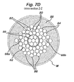
- Figures 6 and 7A-7D generally illustrate the resulting configuration of wire mesh components for this embodiment, which is described in greater detail hereinafter.
- the reactor in accordance with the inventive embodiment of this example, was safely operated under the following feed conditions: Inlet Temperature 207°C Inlet Pressure 22 psig % Propylene 7.80 % Propane 0.50 % N2 65.43 % O2 14.62 % H2O 10.40 % CO2 + CO 0.50 %
- Other - includes: acetic, formic, maleic, & acrylic acid; acetaldehyde; acetone; acrolein; formaldehyde; and argon 0.75
- an elevational side view of the reactor inlet-head assembly 30 is shown, connected to the reactor 32 (only partially shown) so as to form an enclosed headspace (defined inlet region 34) with the inlet tube sheet 36.
- An inlet piping flange 38 is positioned on the centerline 40 of the inlet-head assembly 30 to allow feed gas (not shown per se) to enter the headspace (defined inlet region 34).
- the reactor inlet-head assembly 30 comprises a torispherical head 42 welded to an 1855 millimeter (6.1 feet) long, straight-wall channel section 44.
- the headspace dimensions of the reactor are, therefore, about 6750 millimeters (22 feet) in diameter and about 3125 millimeters (10.25 feet) tall overall as measured at the centerline 40 of the inlet-head assembly 30.
- the enclosed headspace 34 has a volume of 96.1 cubic meters (3393 cubic feet).
- the specific wire mesh used to make the components of this embodiment was a knitted wire mesh, comprising 0.0105 inch diameter 304L Stainless Steel wire - commonly referred to as "bulk mesh” - which was crimped and rolled to achieve a density of 288 kilograms/cubic meter (18 pounds/cubic foot) and obtained from ACS Industries of Hartford, CT.
- Suitable wire mesh can also be commercially obtained from Koch-Otto York Separations Technology of Wichita, KS or Metex Corporation of Edison, NJ.
- such wire mesh is constructed as a knitted tube and is then either flattened for use in a double-ply “blanket” form, or split for use in a single-ply sheet form.
- a combination of wire mesh components comprising cylinders and rectangular pads, were placed within the enclosed headspace 34.
- cylindrical wire mesh components rectangular sections of two-ply wire mesh were first crimped and then coiled to form a cylinder of a specified final height and diameter, with a bulk density of about 288 kilograms/cubic meter (18 pounds/cubic foot), with a tolerance of +/- 0.5 pound/cubic foot.
- rectangular pad wire mesh components (“blankets"), rectangular sections of two-ply wire mesh were first crimped and then layered to form a rectangular pad of a specified final length, width, and height, with a bulk density of about 288 kilograms/cubic meter (18 pounds/cubic foot).
- uncrimped two-ply wire mesh may be used to form wire mesh rolls and wire mesh blankets with a bulk density of about 416 kilogram/cubic meter (26 pounds/cubic foot).
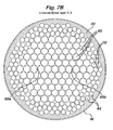
- the five levels within the defined inlet area 34 closest to the tube sheet i.e., levels R-R, S-S, T-T, U-U and V-V (see Figure 6 ), respectively, were packed similarly, as shown in Figure 7A , since they were of the same geometry, particularly, the same diameter.
- wire mesh rolls 50 that were 18 inches in diameter and 14.6 inches high were used to fill the majority of the headspace at these levels, while wire mesh rolls 52 sized 12 inches in diameter and 14.6 inches high were positioned around the perimeter of the plurality of larger wire mesh rolls 50.
- wire mesh rolls 54 having 2.6 inches in diameter and being 14.6 inches high were positioned in void spaces between the largest wire mesh rolls 50 to fill at least some of the void spaces between those large wire mesh rolls 50.
- the wire mesh rolls of height 14.6 inches were stacked, end-to-end, on top of one another, in a staggered manner to break up the void channels that would otherwise be formed.
- Wire mesh blankets 56 sized 3 inches thick, 73 inches high and 24 inches wide were compressed in a layer around the perimeter of the defined inlet region and cover the total height of levels R-R, S-S, T-T, U-U and V-V. Smaller wire mesh blankets 58 sized 3 inches thick, 14.6 inches high and 12 inches wide were inserted in the voids spaces between the larger wire mesh blankets 56 and the medium sized wire mesh rolls 52 around the perimeter.
- Figure 7B shows the configuration of wire mesh rolls and blankets at level X-X, which has a smaller diameter than the aforementioned five levels represented by
- FIG. 7A a combination of wire mesh rolls and blankets was again employed with the largest rolls 60 on this level X-X being 18 inches in diameter and 13 inches high and being placed centrally so as to occupy the majority of the cross-sectional area of the level.
- Smaller wire mesh rolls 62 having 12 inches diameter, but the same height at 13 inches, were placed around the perimeter of the largest wire mesh rolls 60.
- Additional wire mesh rolls 64 having the same 12 inches diameter, but being even at 8 inches high, to accommodate the tapered wall of the headspace 34 (defined inlet region) at this height, were placed around the perimeter of the smaller wire mesh rolls 62.
- the outermost volume of level X-X, around the perimeter of the 8-inch tall wire mesh rolls 64 was filled with wire mesh blankets 66.
- the wire mesh components may be trimmed, i.e., portions cut away, to accommodate such obstacles, as is readily understood by persons of ordinary skill in the art.
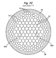
- Figure 7C shows the configuration of wire mesh rolls and blankets at level Y-Y, which has a still smaller diameter than the aforementioned level X-X represented by
- the largest wire mesh rolls 70 measure 18 inches in diameter and 13 inches in height and were placed centrally in the cross-sectional area of level Y-Y.
- Wire mesh rolls 72 having 12 inches diameter and only 6 inches in height were placed around the perimeter of the largest wire mesh rolls 70, and even shorter wire mesh rolls 74, which also have 12-inch diameter, but were only 4 inches in height, were placed around the perimeter of the 6-inch-high wire mesh rolls 72.
- Wire mesh blankets 76 were used to fill the remaining space between the 4-inch-high wire mesh rolls 74 and the vessel wall W.
- the posts 68a and 68b extend downward from level X-X and into level Y-Y, so that at least a few of the 12-inch-high wire mesh rolls 72 were trimmed as in the previous level.
- Figure 7D shows the configuration of wire mesh rolls and blankets at level Z-Z, which has a still smaller diameter than the aforementioned level Y-Y represented by
- FIG. 7C As shown, wire mesh rolls of different heights, but all having 12-inch diameters, were used to fill level Z-Z. More particularly, the tallest wire mesh rolls 80 used in level Z-Z were 11 in height, and the next tallest wire mesh rolls 82, which were placed around the perimeter of the tallest rolls 80, have a height of 8 inches. Wire mesh rolls 84 that were 6 inches high (still with 12-inch diameters) were placed about the perimeter of the 11-inch-high wire mesh rolls 82, and still shorter wire mesh rolls 86, having a height of only 4 inches, were placed around the perimeter of the 6-inch-high wire mesh rolls 84. As in every other level, wire mesh blankets 88 were placed around the perimeter of the outermost wire mesh rolls 86 to fill the remaining space to the vessel wall W.
- the wire diameter of one or more components of attenuating materials may be varied - for example, a wire diameter of 0.008 inch, or of 0.011 inch may be used - and the wire mesh size of the knit for one or more components may be varied - for example, 30 needle mesh, or 90 needle mesh, may be used - without deviating from the spirit of the inventive method.
- Such changes, in combination with optional crimping, may be made to optimize variables such as cost, ease of handling, bulk density, and durability and are within the ability of one of ordinary skill in the art, given the benefit of the present disclosure.
- the wire mesh may comprise copper to resist polymeric fouling by components that may be present in recycled gases.
- the wire mesh may comprise magnetic stainless steel.
- the mesh is formed from knit ceramic fibers comprising one or more materials selected from silica, alumina, and zirconia.
- the process vessel comprises multiple shell and tube reactors arranged in tandem, with or without intermediate cooling exchangers, each reactor containing a catalyst composition for facilitating one or more chemical reactions, with or without sub-zones
- the attenuating material may be placed in one or more of: the defined outlet region of an upstream shell and tube reactor, the optional intermediate heat exchangers, and the inlet of the subsequent downstream shell and tube reactor.
- the outlet gas composition of the upstream reactor may comprise one or more compounds capable of forming a combustible gas mixture in subsequent downstream process vessels.
- supplemental oxidant e.g., air or other mixtures comprising oxygen
- a process vessel used for catalytic oxidation concerns a process vessel used for catalytic oxidation
- the method and apparatus of the present invention are equally and beneficially applicable to process vessels configured to perform other types of chemical reactions, such as, for example, ammoxidation of methane in an Adrussow hydrogen cyanide reactor.
- a cyanide-producing reaction vessel may have a conical-shaped headspace ("defined inlet region") which is at least 50% filled with reticulated ceramic foam.
- Deflagration attenuation in accordance with the method of the present invention is particularly beneficial when hydrogen cyanide reactors are operated under flammable feed conditions; such conditions may occur, for example, when the reactor is operated at greater than atmospheric pressure (e.g., pressures of 30psig or more), or when the reactor is operated with oxygen-enriched feeds. Due to the especially energetic pressure rises that may occur upon combustion of combustible gas feed within oxygen-enriched hydrogen cyanide reactors, it is especially preferred to employ the method of the present invention to hydrogen cyanide reactors wherein the ratio of oxygen to nitrogen in the feed gas, as measured in the region immediately upstream of the catalyst, is greater than about 25:75, for example, greater than about 30:70, or even greater than about 50:50.
- the process vessel was a shell and tube (i.e., tubular) type oxidation reactor, similar to the reactor of Figure 1 , and was operated in a downflow configuration, with combustible gas entering the top head of the vessel at an operating pressure of 3.42bar (35psig) and an operating temperature of 225°C.
- the existing reactor was not fitted with emergency pressure relief devices, such as rupture disks, and so must be capable of containing the pressure increase from any deflagration events.
- the inlet head of the vessel had an internal diameter of 675cm (22 feet) and sufficient wall thickness to provide a maximum allowable containment pressure, P(c), of 12bar (160psig) under these operating conditions.
- P(c) maximum allowable containment pressure
- the combustible gas composition in the defined region of the inlet reactor head was 5.5 vol% propylene, 19.5% oxygen, 73.3% nitrogen, and 1.7% water.
- deflagration pressure in the reactor inlet head may be attenuated by completely filling the defined region of the reactor inlet head with 90mm hollow alumina spheres (commercially available from DeepSea Power & Light of San Diego, CA USA). Although these spheres are fabricated from 99.9% alumina, they have a bulk density less than that of water, beneficially minimizing the total weight of attenuating material that the reactor must support.
- Attenuating materials having small-scale components were first evaluated in the laboratory-scale test apparatus to assess their capability for pressure attenuation in the example system.
- tests were performed with 6mm solid ceramic spheres, 6mm x 10mm solid ceramic cylinders, and 20ppi ceramic foam.
- a 10-liter adiabatic explosion-test apparatus designed in accordance with the requirements for European Standards DIN EN 13673-1 and DIN EN 13673-2, September 2003, was used.
- the apparatus included a 10 liter insulated test sphere with an internal radius of 13.4cm (5.3 inches).
- the sphere was fitted with a fast-acting pressure transducer (model HEM-375-TM, manufactured by Kulite Semiconductor Products of New Jersey, USA), as well as two thermocouples, and an electric ignition source.
- test gas composition matching the intended combustible gas composition of 5.5 vol% propylene, 19.5% oxygen, 73.3% nitrogen, and 1.7% water was prepared by mixing pure component gases in a heated premixing vessel. This test gas composition was used for all Pmax determinations in this example.
- Test A Empty Vessel
- the empty test vessel (containing no attenuating material) was first evacuated ( ⁇ 1 mbar pressure).
- the premixed test gas mixture was then introduced into the vessel to achieve an internal gas pressure of 3.4 bar (35 psig) and an initial temperature of 225°C.
- the gas was then ignited and the pressures and temperatures monitored to obtain a measurement of Pmax for the resulting deflagration in the empty test vessel.
- Test B Solid Ceramic Spheres
- DENSTONE 57 support spheres commercially available from Norton Chemical Products Corp. of Akron, Ohio, USA
- the vessel was next evacuated and then charged with test gas to achieve an internal gas pressure of 3.4 bar (35 psig) and an initial temperature of 225°C. The gas was then ignited to obtain a measurement of Pmax of the resulting deflagration in the test vessel with ceramic spheres.
- the effective diameter, Ds, of these ceramic spheres is determined to be 0.64cm (1/4").
- DMF deflagration mixing factor
- the vessel was evacuated and then charged with test gas to achieve an internal gas pressure of 3.4 bar (35 psig) and an initial temperature of 225°C.
- the gas was then ignited to obtain a measurement of Pmax of the resulting deflagration event in the test vessel with ceramic foam.
- the effective diameter, Ds, of the ceramic foam can be determined easily by simply converting the pores-per-inch (ppi) measure to centimeters.
- Table 3 Component Shape/Geometry Ds, (cm) DMF Pmax (bar) (psig) A Empty Vessel - - - - - - 0.00 19.2 263.3 B Ceramic Sphere 6mm diameter 0.64 1.90 7.8 98.0 C Ceramic Cylinder 10mm long x 6mm dia. 1.14 3.42 9.6 124.0 D Ceramic Foam 20 ppi 0.127 0.38 6.8 83.9
- any attenuating materials selected for use in accordance with the method of the present invention must have a DMF of less than about 14 inches in order to provide any measurable attenuation of Pmax in the example system.
- the DMF for the 90mm hollow alumina spheres was determined next.
- the internal volume of the cylindrical wire-screen cage was varied as a means to adjust the volume of pressure attenuating material within the test vessel.
- Three sizes of wire-screen cage were used: 0.28-liter, 0.57- liter, and 2.4-liter.
- test gas composition 5.5 vol% propylene, 19.5% oxygen, 73.3% nitrogen, and 1.7% water was prepared by mixing pure component gases in a heated premixing vessel. This test gas composition was used for all Pmax determinations in this example.
- the test vessel igniter was fitted with a 2.4 liter wire-screen cage. Approximately 10.7 kg of 6mm (1 ⁇ 4") diameter DENSTONE 57 Support Spheres (commercially available from Norton Chemical Products Corp. of Akron, Ohio, USA) were poured into the test vessel and allowed to self-assemble (no manual adjustments were made to the packing density). This represented a 76% volume-fill of ceramic spheres (7.6 liters of spheres + 2.4 liters of space within the wire-screen cage). As in the previous case, the vessel was next evacuated and then charged with test gas to achieve an internal gas pressure of 3.4 bar (35 psig) and an initial temperature of 225°C. The gas was then ignited to obtain a measurement of Pmax of the resulting deflagration event in the test vessel with ceramic spheres.
- the test vessel igniter was fitted with a 0.57 liter (9cm diameter by 9cm long) wire-screen cage. Approximately 13.4 kg of 6mm (1 ⁇ 4-inch) diameter DENSTONE 57 Support Spheres (commercially available from Norton Chemical Products Corp. of Akron, Ohio, USA) were poured into the same test vessel and allowed to self-assemble (no manual adjustments were made to the packing density). This represented a 94% volume-fill of ceramic spheres (9.43 liters of spheres + 0.57 liters of space within the wire-screen cage). As in the previous case, the vessel was next evacuated and then charged with test gas to achieve an internal gas pressure of 3.4 bar (35 psig) and an initial temperature of 225°C. The gas was then ignited to obtain a measurement of Pmax of the resulting deflagration event in the test vessel with ceramic spheres.
- the test vessel igniter was fitted with a 0.28 liter (9cm diameter by 4.5cm long) wire-screen cage. Approximately 14kg of 6mm (1 ⁇ 4-inch) diameter DENSTONE 57 Support Spheres (commercially available from Norton Chemical Products Corp. of Akron, Ohio, USA) were poured into the same test vessel and allowed to self-assemble (no manual adjustments were made to the packing density). This represented a 97% volume-fill of ceramic spheres (9.72 liters of spheres + 0.28 liters of space within the wire-screen cage). As in the previous case, the vessel was next evacuated and then charged with test gas to achieve an internal gas pressure of 3.4 bar (35 psig) and an initial temperature of 225°C. The gas was then ignited to obtain a measurement of Pmax of the resulting deflagration event in the test vessel with ceramic spheres.
- Table 4 Component Void Volume ( liters ) % Volume-Fill Pmax (bar) (psig) A Empty Vessel 10 0% 19.2 263.3 E 6mm Ceramic Sphere 2.4 76% 10.5 138.0 F 6mm Ceramic Sphere 0.57 94% 7.8 98.0 G 6mm Ceramic Sphere 0.28 97% 7.0 86.1
- Pall Rings are one common example of an attenuating material having components with at least one through passage.
- Table 5 Component External Geometry Number of Through-passages Pmax (bar) (psig) A Empty Vessel - - - - - - 19.2 263 K Proware TM Ty-pak ® Bow-tie 2 13.3 178 L Proware TM Ty-pak ® Bow-tie 2 12.1 161 M Proware TM Ty-pak ® Bow-tie 2 13.2 177 N HexPak TM 90 Hexagon 91 16.4 223 O HexPak TM 90 Hexagon 91 17.5 239
- test gas composition of 5.5 vol% propylene, 19.5% oxygen, 73.3% nitrogen, and 1.7% water was prepared by mixing pure component gases in a heated premixing vessel. This test gas composition was used for all Pmax determinations in this example.
- Crimped wire mesh cylinders were prepared from rectangular sheets of crimped, 18lb/cuft, 304L stainless steel wire mesh. The sheets were rolled into cylinders measuring about 7.6cm (3 inches) in diameter and about 15.2cm (6 inches) in length. Some of these cylinders were used as-is, while some were cut to shorter length in order to better fit the curvature of the test vessel. Approximately 2.4 kg of crimped wire mesh cylinders were manually placed into the test vessel to provide a closely packed fill that minimized voids and channels. This represented a 93% volume-fill of mesh cylinders.
- wire mesh can be compressed, it is possible to provide a close-fit that cannot be achieved with rigid components such as ceramic spheres or ceramic foam.
- the DMF value was developed to account for the easily reproducible effects of geometry, size, and packing fraction of rigid components, rather than compressible components. As a result, it does not appear that the DMF concept can be reliably applied to the scale-up to wire mesh components; if one chooses to use wire mesh cylinders, it is recommended that direct testing be performed as described herein to assure proper implementation of the inventive concept and further, that substantial care be taken to make the packing of such components as reproducible as possible.
- wire mesh blankets can be used within a process vessel in accordance with the method of the present invention, such blankets - especially when used as the majority component within the process vessel - are susceptible to settling and compression.
- wire mesh first be rolled into cylinders before placement within the process vessel in order to provide greater resistance to settling and compression.
- uncrimped wire mesh may be used to form wire mesh cylinders, or crimped wire mesh may be used, in order to minimize the total weight of the attenuating materials in the process vessel.
Landscapes
- Chemical & Material Sciences (AREA)
- Engineering & Computer Science (AREA)
- Organic Chemistry (AREA)
- Chemical Kinetics & Catalysis (AREA)
- Combustion & Propulsion (AREA)
- Mechanical Engineering (AREA)
- General Engineering & Computer Science (AREA)
- Physical Or Chemical Processes And Apparatus (AREA)
- Hydrogen, Water And Hydrids (AREA)
- Devices And Processes Conducted In The Presence Of Fluids And Solid Particles (AREA)
Applications Claiming Priority (1)
| Application Number | Priority Date | Filing Date | Title |
|---|---|---|---|
| US7250208P | 2008-03-31 | 2008-03-31 |
Publications (3)
| Publication Number | Publication Date |
|---|---|
| EP2106848A2 true EP2106848A2 (de) | 2009-10-07 |
| EP2106848A3 EP2106848A3 (de) | 2017-09-13 |
| EP2106848B1 EP2106848B1 (de) | 2019-10-02 |
Family
ID=40833590
Family Applications (1)
| Application Number | Title | Priority Date | Filing Date |
|---|---|---|---|
| EP09155306.5A Active EP2106848B1 (de) | 2008-03-31 | 2009-03-17 | Verfahren und Vorrichtung zur Verpuffungsdruckabschwächung |
Country Status (7)
| Country | Link |
|---|---|
| US (1) | US8002047B2 (de) |
| EP (1) | EP2106848B1 (de) |
| JP (1) | JP5006358B2 (de) |
| CN (1) | CN101584916B (de) |
| BR (1) | BRPI0900957B1 (de) |
| MX (1) | MX2009003274A (de) |
| TW (1) | TWI390145B (de) |
Cited By (3)
| Publication number | Priority date | Publication date | Assignee | Title |
|---|---|---|---|---|
| WO2014099570A1 (en) * | 2012-12-18 | 2014-06-26 | Invista Technologies S.A R.L. | Operational controls for inert gas blanketing for andrussow process |
| CN113158489A (zh) * | 2021-05-13 | 2021-07-23 | 中国石油大学(华东) | 一种基于等效载荷的抗爆管道壁厚的计算方法 |
| DE102023101925A1 (de) | 2023-01-26 | 2024-08-01 | Man Energy Solutions Se | Rohrbündelreaktor |
Families Citing this family (17)
| Publication number | Priority date | Publication date | Assignee | Title |
|---|---|---|---|---|
| JP5083289B2 (ja) * | 2009-10-19 | 2012-11-28 | トヨタ自動車株式会社 | タンク及びタンクの製造方法 |
| JP5942391B2 (ja) * | 2011-11-15 | 2016-06-29 | Jsr株式会社 | 反応管、多管式反応器及びこれを用いた不飽和化合物の製造方法 |
| EP2856144B1 (de) | 2012-06-04 | 2020-01-08 | Apix Analytics | Vorrichtung zur flüssigkeitsanalyse mit einem brennbaren medium sowie entsprechendes verfahren |
| US20130333445A1 (en) * | 2012-06-04 | 2013-12-19 | Eif - Astute | Analyzer for fluids containing an inflammable substance and corresponding method |
| US20160136467A1 (en) * | 2014-11-18 | 2016-05-19 | Air Liquide Large Industries U.S. Lp | Detonation arrestor for cavern storage |
| US20180056100A1 (en) * | 2016-08-31 | 2018-03-01 | Emerson Process Management Regulator Technologies Tulsa, Llc | Method for Manufacturing a Flame Arrestor |
| US9987508B2 (en) | 2016-08-31 | 2018-06-05 | Emerson Process Management Regulator Technologies Tulsa, Llc | Hybrid composite flame cell |
| US10286241B2 (en) * | 2017-03-28 | 2019-05-14 | The Boeing Company | Combustion arrester quantification systems and methods |
| US10543387B2 (en) | 2017-03-28 | 2020-01-28 | The Boeing Company | Combustion arrester test systems and methods |
| US10119779B1 (en) | 2017-06-27 | 2018-11-06 | Smith & Wesson Corp. | Suppressor for firearm and baffle cup therefor |
| CN109212154B (zh) * | 2018-07-03 | 2023-11-10 | 中国人民解放军陆军工程大学 | 气体爆炸热力耦合破坏效应实验装置 |
| CN110028061B (zh) * | 2019-04-12 | 2020-08-28 | 青岛华高墨烯科技股份有限公司 | 一种石墨烯制备降温降压消尘装置 |
| CN112666209B (zh) * | 2020-12-02 | 2022-07-19 | 西南交通大学 | 一种强迫油循环导向绕组传热强化能力的评估方法 |
| CN113639521B (zh) * | 2021-08-04 | 2022-12-13 | 南京密尔克卫化工供应链服务有限公司 | 一种化工防爆系统 |
| CN116026980B (zh) * | 2022-12-17 | 2025-03-07 | 河南大学 | 一种加快燃烧波衰减的系统及方法 |
| CN119793340A (zh) * | 2023-10-11 | 2025-04-11 | 中国石油化工股份有限公司 | 一种防爆反应器及应用 |
| WO2025155820A1 (en) * | 2024-01-19 | 2025-07-24 | Evoqua Water Technologies Llc | System and method for vapor space monitoring and control |
Citations (13)
| Publication number | Priority date | Publication date | Assignee | Title |
|---|---|---|---|---|
| US3356256A (en) | 1965-10-23 | 1967-12-05 | Szego Joseph | Safety container for explosive fluids |
| US4613054A (en) | 1984-09-20 | 1986-09-23 | Hannes Schrenk | Filler body for receptacles for combustible fluids and method of making same |
| US5495893A (en) | 1994-05-10 | 1996-03-05 | Ada Technologies, Inc. | Apparatus and method to control deflagration of gases |
| US6540029B2 (en) | 2001-02-23 | 2003-04-01 | Fike Corporation | Deflagration and explosion suppression and isolation apparatus for contained hazardous material |
| US6649137B2 (en) | 2000-05-23 | 2003-11-18 | Rohm And Haas Company | Apparatus with improved safety features for high temperature industrial processes |
| US6932950B1 (en) | 1998-02-18 | 2005-08-23 | Man Dwe Gmbh | Tubular reactor for catalytic gas phase reactions |
| US7000630B2 (en) | 2003-11-21 | 2006-02-21 | Eastman Kodak Company | Flame front diverter element |
| US20060111575A1 (en) | 2004-11-22 | 2006-05-25 | Decourcy Michael S | Non-routine reactor shutdown method |
| US7074955B2 (en) | 2002-07-17 | 2006-07-11 | Basf Aktiengesellschaft | Safe operation of a continuous heterogeneously catalyzed gas-phase partial oxidation of at least one organic compound |
| US20060166365A1 (en) | 2003-07-14 | 2006-07-27 | Mitsubishi Rayon Co., Ltd. | Method for supplying reaction gases in catalytic vapor phase oxidation process |
| US7102030B2 (en) | 2003-03-14 | 2006-09-05 | Nippon Shokubai, Co., Ltd | Method for managing operation of gas phase reaction apparatus |
| US20060292046A1 (en) | 2003-07-31 | 2006-12-28 | Dow Global Technologies Inc. | Oxidation process and reactor with modified feed system |
| US7326810B2 (en) | 2000-08-07 | 2008-02-05 | Nippon Shokubai Co., Ltd. | Method for starting up reactor |
Family Cites Families (13)
| Publication number | Priority date | Publication date | Assignee | Title |
|---|---|---|---|---|
| JPS5432408A (en) * | 1977-08-13 | 1979-03-09 | Mitsubishi Petrochem Co Ltd | Preparation of ethylene oxide and its reaction vessel |
| US4751154A (en) * | 1987-08-21 | 1988-06-14 | Globe-Union Inc. | Battery explosion attenuation material and method |
| ES2079933T3 (es) | 1993-08-24 | 1996-01-16 | Anlagen Und Reaktorsicherheit | Disposicion para la inertizacion pasiva de la mezcla de gases en la vasija de seguridad de una central nuclear. |
| JPH07235325A (ja) * | 1994-02-23 | 1995-09-05 | Aisin Seiki Co Ltd | 鉛蓄電池 |
| US5718293A (en) | 1995-01-20 | 1998-02-17 | Minnesota Mining And Manufacturing Company | Fire extinguishing process and composition |
| US5617208A (en) | 1995-02-03 | 1997-04-01 | Huntsman Petrochemical Corporation | Ignition detection method and device for a reaction vessel |
| US5750278A (en) * | 1995-08-10 | 1998-05-12 | Westinghouse Electric Corporation | Self-cooling mono-container fuel cell generators and power plants using an array of such generators |
| AU702825C (en) * | 1995-09-01 | 2002-09-19 | Lucite International Uk Limited | Hydrogen cyanide process and apparatus therefor |
| US5613453A (en) | 1995-12-29 | 1997-03-25 | Donovan; John L. | Method and apparatus for containing and suppressing explosive detonations |
| US20010022302A1 (en) * | 1999-12-22 | 2001-09-20 | Eric Dunn | Vaulted fluid storage systems |
| WO2004067164A1 (de) * | 2003-01-31 | 2004-08-12 | Man Dwe Gmbh | Mantelrohrreaktor zur durchführung katalytischer gasphasenreaktionen und verfahren zum betreiben eines solchen |
| FR2851246A1 (fr) * | 2003-02-14 | 2004-08-20 | Bp Lavera Snc | Procede de fabrication d'oxyde d'ethylene |
| CN1819869A (zh) * | 2003-07-31 | 2006-08-16 | 陶氏环球技术公司 | 氧化方法和具有改良进料系统的反应器 |
-
2009
- 2009-02-27 TW TW098106331A patent/TWI390145B/zh not_active IP Right Cessation
- 2009-03-16 JP JP2009062634A patent/JP5006358B2/ja active Active
- 2009-03-17 EP EP09155306.5A patent/EP2106848B1/de active Active
- 2009-03-26 MX MX2009003274A patent/MX2009003274A/es active IP Right Grant
- 2009-03-27 BR BRPI0900957-4A patent/BRPI0900957B1/pt active IP Right Grant
- 2009-03-30 CN CN2009101283473A patent/CN101584916B/zh active Active
- 2009-03-30 US US12/383,909 patent/US8002047B2/en active Active
Patent Citations (13)
| Publication number | Priority date | Publication date | Assignee | Title |
|---|---|---|---|---|
| US3356256A (en) | 1965-10-23 | 1967-12-05 | Szego Joseph | Safety container for explosive fluids |
| US4613054A (en) | 1984-09-20 | 1986-09-23 | Hannes Schrenk | Filler body for receptacles for combustible fluids and method of making same |
| US5495893A (en) | 1994-05-10 | 1996-03-05 | Ada Technologies, Inc. | Apparatus and method to control deflagration of gases |
| US6932950B1 (en) | 1998-02-18 | 2005-08-23 | Man Dwe Gmbh | Tubular reactor for catalytic gas phase reactions |
| US6649137B2 (en) | 2000-05-23 | 2003-11-18 | Rohm And Haas Company | Apparatus with improved safety features for high temperature industrial processes |
| US7326810B2 (en) | 2000-08-07 | 2008-02-05 | Nippon Shokubai Co., Ltd. | Method for starting up reactor |
| US6540029B2 (en) | 2001-02-23 | 2003-04-01 | Fike Corporation | Deflagration and explosion suppression and isolation apparatus for contained hazardous material |
| US7074955B2 (en) | 2002-07-17 | 2006-07-11 | Basf Aktiengesellschaft | Safe operation of a continuous heterogeneously catalyzed gas-phase partial oxidation of at least one organic compound |
| US7102030B2 (en) | 2003-03-14 | 2006-09-05 | Nippon Shokubai, Co., Ltd | Method for managing operation of gas phase reaction apparatus |
| US20060166365A1 (en) | 2003-07-14 | 2006-07-27 | Mitsubishi Rayon Co., Ltd. | Method for supplying reaction gases in catalytic vapor phase oxidation process |
| US20060292046A1 (en) | 2003-07-31 | 2006-12-28 | Dow Global Technologies Inc. | Oxidation process and reactor with modified feed system |
| US7000630B2 (en) | 2003-11-21 | 2006-02-21 | Eastman Kodak Company | Flame front diverter element |
| US20060111575A1 (en) | 2004-11-22 | 2006-05-25 | Decourcy Michael S | Non-routine reactor shutdown method |
Non-Patent Citations (7)
| Title |
|---|
| "Deflagration and Detonation Flame Arresters, AIChE", 2002, CENTER FOR CHEMICAL PROCESS SAFETY, pages: 77 - 138 |
| EUROPEAN STANDARD DIN EN 1839, January 2004 (2004-01-01) |
| EUROPEAN STANDARDS DIN EN 13673-1 AND DIN EN 13673-2, September 2003 (2003-09-01) |
| FAUSKE, HANS K.: "Expanded-Metal Networks: A Safety Net to Thwart Gas Explosions", CHEMICAL ENGINEERING PROGRESS, December 2001 (2001-12-01), pages 66 - 71 |
| RAZUS D. ET AL.: "Closed vessel combustion of propylene-air mixtures in the presence of exhaust gas", FUEL, 2007 |
| W. BARTKNECHT: "Explosions", 1981, SPRINGER-VERLAG |
| W. L. MCCABE; J.C. SMITH: "Unit Operations of Chemical Engineering", 1976, MCGRAW-HILL |
Cited By (4)
| Publication number | Priority date | Publication date | Assignee | Title |
|---|---|---|---|---|
| WO2014099570A1 (en) * | 2012-12-18 | 2014-06-26 | Invista Technologies S.A R.L. | Operational controls for inert gas blanketing for andrussow process |
| CN113158489A (zh) * | 2021-05-13 | 2021-07-23 | 中国石油大学(华东) | 一种基于等效载荷的抗爆管道壁厚的计算方法 |
| DE102023101925A1 (de) | 2023-01-26 | 2024-08-01 | Man Energy Solutions Se | Rohrbündelreaktor |
| WO2024156524A1 (de) | 2023-01-26 | 2024-08-02 | Man Energy Solutions Se | Rohrbündelreaktor |
Also Published As
| Publication number | Publication date |
|---|---|
| BRPI0900957B1 (pt) | 2020-03-10 |
| CN101584916B (zh) | 2012-05-30 |
| US8002047B2 (en) | 2011-08-23 |
| JP5006358B2 (ja) | 2012-08-22 |
| TW200940866A (en) | 2009-10-01 |
| EP2106848B1 (de) | 2019-10-02 |
| BRPI0900957A2 (pt) | 2010-07-20 |
| CN101584916A (zh) | 2009-11-25 |
| JP2009255060A (ja) | 2009-11-05 |
| EP2106848A3 (de) | 2017-09-13 |
| TWI390145B (zh) | 2013-03-21 |
| MX2009003274A (es) | 2009-10-05 |
| US20090277655A1 (en) | 2009-11-12 |
Similar Documents
| Publication | Publication Date | Title |
|---|---|---|
| EP2106848B1 (de) | Verfahren und Vorrichtung zur Verpuffungsdruckabschwächung | |
| EP0649327B1 (de) | Flammen- und explosionsschutzsicherung | |
| EP1874411B1 (de) | Detonationsflammensperre | |
| KR100810446B1 (ko) | 고온 산업 공정에서의 향상된 안전 특성을 가진 장치 | |
| CN106170320B (zh) | 阻火器 | |
| KR102139695B1 (ko) | 폭발 압력 배출 및 화염 방출 방지 장치 | |
| CN101678297B (zh) | 用于催化的气相反应的装置和方法及其应用 | |
| US8852538B2 (en) | Reactor for carrying out an autothermal gas-phase dehydrogenation | |
| JP2007521126A (ja) | 改良された供給システムを用いる酸化方法及び反応器 | |
| CN108926990A (zh) | 一种用于VOCs气体净化的催化反应器 | |
| CN103702753B (zh) | 用于实施自热气相脱氢的反应器 | |
| KR101105336B1 (ko) | 폭연 압력 감소를 위한 방법 및 장치 | |
| EA005982B1 (ru) | Способ и устройство для загрузки твердых частиц в вертикальную трубу | |
| KR101831507B1 (ko) | 등온반응 유도용 자체 열공급 탈수소 반응기 | |
| WO2021023613A1 (en) | Method for preventing the fluidization of a catalytic fixed bed in a tubular upward-flow reactor of a steam methane reformer | |
| CA2139360C (en) | Flame arrestor apparatus | |
| RU1782641C (ru) | Реактор дл проведени каталитических процессов | |
| CN120826273A (zh) | 管束反应器 |
Legal Events
| Date | Code | Title | Description |
|---|---|---|---|
| PUAI | Public reference made under article 153(3) epc to a published international application that has entered the european phase |
Free format text: ORIGINAL CODE: 0009012 |
|
| 17P | Request for examination filed |
Effective date: 20090317 |
|
| AK | Designated contracting states |
Kind code of ref document: A2 Designated state(s): AT BE BG CH CY CZ DE DK EE ES FI FR GB GR HR HU IE IS IT LI LT LU LV MC MK MT NL NO PL PT RO SE SI SK TR |
|
| AX | Request for extension of the european patent |
Extension state: AL BA RS |
|
| PUAL | Search report despatched |
Free format text: ORIGINAL CODE: 0009013 |
|
| AK | Designated contracting states |
Kind code of ref document: A3 Designated state(s): AT BE BG CH CY CZ DE DK EE ES FI FR GB GR HR HU IE IS IT LI LT LU LV MC MK MT NL NO PL PT RO SE SI SK TR |
|
| AX | Request for extension of the european patent |
Extension state: AL BA RS |
|
| RIC1 | Information provided on ipc code assigned before grant |
Ipc: B01J 8/02 20060101ALI20170807BHEP Ipc: B01J 8/06 20060101AFI20170807BHEP Ipc: B01J 19/00 20060101ALI20170807BHEP |
|
| STAA | Information on the status of an ep patent application or granted ep patent |
Free format text: STATUS: EXAMINATION IS IN PROGRESS |
|
| 17Q | First examination report despatched |
Effective date: 20170921 |
|
| AKX | Designation fees paid |
Designated state(s): DE FR GB |
|
| AXX | Extension fees paid |
Extension state: RS Extension state: AL Extension state: BA |
|
| GRAP | Despatch of communication of intention to grant a patent |
Free format text: ORIGINAL CODE: EPIDOSNIGR1 |
|
| STAA | Information on the status of an ep patent application or granted ep patent |
Free format text: STATUS: GRANT OF PATENT IS INTENDED |
|
| INTG | Intention to grant announced |
Effective date: 20190430 |
|
| GRAS | Grant fee paid |
Free format text: ORIGINAL CODE: EPIDOSNIGR3 |
|
| GRAA | (expected) grant |
Free format text: ORIGINAL CODE: 0009210 |
|
| STAA | Information on the status of an ep patent application or granted ep patent |
Free format text: STATUS: THE PATENT HAS BEEN GRANTED |
|
| AK | Designated contracting states |
Kind code of ref document: B1 Designated state(s): DE FR GB |
|
| REG | Reference to a national code |
Ref country code: GB Ref legal event code: FG4D |
|
| REG | Reference to a national code |
Ref country code: DE Ref legal event code: R096 Ref document number: 602009059992 Country of ref document: DE |
|
| REG | Reference to a national code |
Ref country code: DE Ref legal event code: R097 Ref document number: 602009059992 Country of ref document: DE |
|
| PLBE | No opposition filed within time limit |
Free format text: ORIGINAL CODE: 0009261 |
|
| STAA | Information on the status of an ep patent application or granted ep patent |
Free format text: STATUS: NO OPPOSITION FILED WITHIN TIME LIMIT |
|
| 26N | No opposition filed |
Effective date: 20200703 |
|
| GBPC | Gb: european patent ceased through non-payment of renewal fee |
Effective date: 20200317 |
|
| PG25 | Lapsed in a contracting state [announced via postgrant information from national office to epo] |
Ref country code: GB Free format text: LAPSE BECAUSE OF NON-PAYMENT OF DUE FEES Effective date: 20200317 |
|
| P01 | Opt-out of the competence of the unified patent court (upc) registered |
Effective date: 20230525 |
|
| PGFP | Annual fee paid to national office [announced via postgrant information from national office to epo] |
Ref country code: FR Payment date: 20251231 Year of fee payment: 18 |
|
| PGFP | Annual fee paid to national office [announced via postgrant information from national office to epo] |
Ref country code: DE Payment date: 20260102 Year of fee payment: 18 |