EP2106723A1 - Seat reclining mechanism - Google Patents
Seat reclining mechanism Download PDFInfo
- Publication number
- EP2106723A1 EP2106723A1 EP08016224A EP08016224A EP2106723A1 EP 2106723 A1 EP2106723 A1 EP 2106723A1 EP 08016224 A EP08016224 A EP 08016224A EP 08016224 A EP08016224 A EP 08016224A EP 2106723 A1 EP2106723 A1 EP 2106723A1
- Authority
- EP
- European Patent Office
- Prior art keywords
- lock
- guide bracket
- gear member
- internal gear
- seat back
- Prior art date
- Legal status (The legal status is an assumption and is not a legal conclusion. Google has not performed a legal analysis and makes no representation as to the accuracy of the status listed.)
- Granted
Links
- 238000000034 method Methods 0.000 claims description 13
- 229940084428 freezone Drugs 0.000 description 32
- YGSDEFSMJLZEOE-UHFFFAOYSA-N salicylic acid Chemical compound OC(=O)C1=CC=CC=C1O YGSDEFSMJLZEOE-UHFFFAOYSA-N 0.000 description 32
- 230000002093 peripheral effect Effects 0.000 description 16
- 230000004048 modification Effects 0.000 description 8
- 238000012986 modification Methods 0.000 description 8
- 230000009467 reduction Effects 0.000 description 6
- 238000009434 installation Methods 0.000 description 2
- 230000000149 penetrating effect Effects 0.000 description 1
Images






Classifications
-
- B—PERFORMING OPERATIONS; TRANSPORTING
- B60—VEHICLES IN GENERAL
- B60N—SEATS SPECIALLY ADAPTED FOR VEHICLES; VEHICLE PASSENGER ACCOMMODATION NOT OTHERWISE PROVIDED FOR
- B60N2/00—Seats specially adapted for vehicles; Arrangement or mounting of seats in vehicles
- B60N2/02—Seats specially adapted for vehicles; Arrangement or mounting of seats in vehicles the seat or part thereof being movable, e.g. adjustable
- B60N2/22—Seats specially adapted for vehicles; Arrangement or mounting of seats in vehicles the seat or part thereof being movable, e.g. adjustable the back-rest being adjustable
- B60N2/235—Seats specially adapted for vehicles; Arrangement or mounting of seats in vehicles the seat or part thereof being movable, e.g. adjustable the back-rest being adjustable by gear-pawl type mechanisms
- B60N2/2356—Seats specially adapted for vehicles; Arrangement or mounting of seats in vehicles the seat or part thereof being movable, e.g. adjustable the back-rest being adjustable by gear-pawl type mechanisms with internal pawls
- B60N2/236—Seats specially adapted for vehicles; Arrangement or mounting of seats in vehicles the seat or part thereof being movable, e.g. adjustable the back-rest being adjustable by gear-pawl type mechanisms with internal pawls linearly movable
Definitions
- the present invention relates to a seat reclining mechanism.
- JP 2001-17259A and JP 2004-154585A disclose a reclining mechanism which comprises a guide bracket adapted to be mounted to either one of a seat cushion and a seat back, an internal gear member (i.e., internally-toothed gear member) adapted to be mounted to a remaining one of the seat cushion and the seat back, a plurality of lock gear members disposed between the guide bracket and the internal gear member and adapted to be slidingly guided in a radial direction, a rotatable cam adapted to move the lock gear members in both a lock direction causing the lock gear members to be brought into engagement with the internal gear member and an unlock direction causing the lock gear members to be released from the engagement with the internal gear member, and a lock spring biasing the rotatable cam in a lock-causing rotation direction.
- a stopper for positioning a seat back at a forwardmost inclined position or a rearwardmost inclined position typically comprises a structure adapted to allow a stopper bracket fixed to a back frame of the seat back to be brought into contact with a stopper portion of a seat cushion.
- the stopper is disposed to protrude outwardly from the reclining mechanism to cause an increase in outside dimension of a seat and impose restrictions on seat layout.
- a need for using a stopper member having relatively large size, such as the stopper bracket, causes a problem about an increase in weight of a seat.
- the present invention provides a seat reclining mechanism designed to be mounted to a seat cushion and a seat back so as to allow the seat back to be reclined.
- the seat reclining mechanism comprises: a guide bracket adapted to be mounted to either one of the seat cushion and the seat back; an internal gear member adapted to be mounted to a remaining one of the seat cushion and the seat back, wherein the internal gear member is coupled to the guide bracket in a rotatable manner about a rotation axis thereof with respect to the guide bracket, and formed with internal teeth along a circle having a center on the rotation axis; a plurality of lock gear members disposed between the guide bracket and the internal gear member to extend radially from the rotation axis, wherein each of the lock gear members is formed with external teeth meshingly engageable with the internal teeth, and supported by the guide bracket in such a manner as to be slidable in both a lock direction causing the external teeth to be brought into meshing engagement with the internal teeth and an unlock direction causing the external teeth to be
- a seat reclining mechanism is designed to be mounted to a seat cushion and a seat back of a seat so as to allow the seat back to be reclined.
- the mechanism comprises a guide bracket 1 adapted to be mounted to the seat cushion, an internal gear member 2 adapted to be mounted to the seat back, four lock gear members 3, a rotatable cam 4, a lock spring 5, a stopper plate 6, and a ring 7.
- the guide bracket 1 is formed in a circular disk shape.
- the guide bracket 1 has a fitting portion which comprises a fitting hole 1a concentrically formed in the guide bracket 1.
- the fitting hole 1a includes a cutout 1b formed to lock an outer end 5a of the lock spring 5 which is a spiral spring.
- the guide bracket 1 has four guide grooves 1c which are formed in an inner surface thereof through a half blanking process to extend from an inner peripheral edge of the fitting hole 1a in a radially outward direction of the guide bracket 1 in a spoke-like pattern.
- the four guide grooves 1c are arranged to form a cross shape, and the fitting hole 1a is formed in a central region of the guide grooves 1c.
- the inner surface of the guide bracket 1 means a surface of the guide bracket 1 located in opposed relation to the internal gear member 2.
- Each of the guide grooves 1c has a columnar-shaped convex portion 1d formed through a half blanking process to protrude outwardly from an outer surface of the guide bracket 1.
- the convex portions 1d serve as a positioning means to be used when the guide bracket 1 is mounted to the seat cushion.
- the guide bracket 1 also has a semi-columnar-shaped forwardmost-inclination stopper protrusion 1f and a semi-columnar-shaped rearwardmost-inclination stopper protrusion 1g which are formed, respectively, in two regions defined between a horizontally-extending right one and a downwardly-extending one of the four guide grooves 1c and between a horizontally-extending left one and the downwardly-extending one of the four guide grooves 1c in FIG. 3A , to protrude inwardly from the inner surface the guide bracket 1.
- These stopper protrusions 1f, 1g are formed through a half blanking process.
- the forwardmost-inclination stopper protrusion 1f and the rearwardmost-inclination stopper protrusion 1g are adapted to come into contact with the stopper plate 6 when the seat back is moved to a forwardmost inclined position and a rearwardmost inclined position, respectively, as will be described in detail later.
- the internal gear member 2 is formed in a circular disk shape.
- the internal gear member 2 is coupled to the guide bracket 1 in a rotatable manner about a rotation axis thereof with respect to the guide bracket 1.
- the center of the guide bracket 1 is located on the rotation axis of the internal gear member 2.
- the internal gear member 2 has two steps of concave portions formed in an inner surface of thereof through a half blanking process. Two sidewalls constituting respective ones of the first-step concave portion 2k and the second-step concave portion 2m are formed, respectively, in a circular shape and a circular arc shape in front view. Each of the circular-shaped sidewall and the circular arc-shaped sidewall are formed in concentric relation with an after-mentioned through-hole 2a.
- the inner surface of the internal gear member 2 means a surface of the internal gear member 2 located in opposed relation to the guide bracket 1.
- the sidewall of the first-step concave portion 2k has internal teeth 2e formed over the entire inner peripheral surface thereof.
- the internal teeth 2e are formed through a half blanking process.
- the second-step concave portion 2m has a bottom wall 2b formed with a through-hole 2a having a diameter less than that of the fitting hole 1a of the guide bracket 1, and six columnar-shaped convex portions 2c each protruding outwardly from an outer surface of the internal gear member 2, and four lock protrusions 2d each protruding inwardly from the inner surface of the internal gear member 2.
- the through-hole 2a has a center located on the rotation axis of the internal gear member 2.
- the convex portions 2c serve as a positioning means to be used when the internal gear member 2 is mounted to the seat back.
- the lock protrusions 2d serve as a means to position and lock the stopper plate 6, as will be described in detail later.
- Each of the convex portions 2c and the lock protrusions 2d are formed through a half blanking process.
- the sidewall of the second-step concave portion 2m is formed to have an inner peripheral surface which comprises a first free-zone arc portion 2f, a first lock-zone arc portion 2h, a second free-zone arc portion 2g, and a second lock-zone arc portion 2j.
- Each of the arc portions 2f, 2h, 2g, 2j has a center located on the rotation axis of the internal gear member 2.
- the first free-zone arc portion 2f is located in opposed relation to the second free-zone arc portion 2g, and the first and second free-zone arc portions 2f, 2g are formed along a common circle.
- the first lock-zone arc portion 2h is located in opposed relation to the second lock-zone arc portion 2j, and the first and second lock-zone arc portions 2h, 2j are formed along a common circle.
- the first free-zone arc portion 2f has an arc length greater than that of the second free-zone arc portion 2g. That is, a center angle ⁇ 1 of the first free-zone arc portion 2f is greater than a center angle ⁇ 2 of the second free-zone arc portion 2g.
- Each of the free-zone arc portions 2f, 2g has a curvature radius less than that of each of the lock-zone arc portions 2h, 2j.
- the free-zone arc portions 2f, 2g are formed to allow an after-mentioned protrusion 3c of one of the lock gear members 3 to be in contact with either one thereof when the lock gear members 3 are located at a position where an after-mentioned external teeth 3a of the lock gear members 3 are not in meshing engagement with the internal teeth 2e of the internal gear member 2.
- the lock-zone arc portions 2h, 2j are formed to allow the after-mentioned protrusion 3c to be in contact with either one thereof when the lock gear members 3 are located at a position where the after-mentioned external teeth 3a are in meshing engagement with the internal teeth 2e.
- the four lock gear members 3 are disposed between the guide bracket 1 and the internal gear member 2 to extend radially from the rotation axis in a cross-like pattern. That is, the four lock gear members are arranged at intervals of about 90 degrees. This provides enhanced stability and safety in a locked state.
- each of the lock gear members 3 has an arc-shaped surface located in opposed relation to the internal teeth 2e of the internal gear member 2 and formed with external teeth 3a meshingly engageable with the internal teeth 2e.
- Each of the lock gear members 3 is supported by a corresponding one of the guide grooves 1c of the guide bracket 1 in such a manner as to be slidable in both a lock direction R2 causing the external teeth 3a to be brought into meshing engagement with the internal teeth 2e and an unlock direction U2 causing the external teeth 3a to be released from the meshing engagement with the internal teeth 2e.
- Each of the lock gear members 3 has an engagement groove 3b formed on a leading side of the unlock direction U2 to allow a corresponding one of after-mentioned engagement pawls 4e of the rotatable cam 4 to be brought into engagement therewith.
- the engagement groove 3b is formed in a shape which allows the after-mentioned engagement pawl 4e to be inserted thereinto when the rotatable cam 4 is rotated in an after-mentioned unlock-causing rotation direction U1.
- one of the four lock gear members 3 has a protrusion 3c protruding toward the internal gear member 2.
- the protrusion 3c is formed through a half blanking process.
- the rotatable cam 4 is rotatably supported by the fitting hole 1a of the guide bracket 1, and adapted to be rotatable in both a lock-causing rotation direction R1 and an unlock-causing rotation direction U1 illustrated in FIG. 5C .
- the rotatable cam 4 has a cam body 4n, four engagement pawls 4e protruding from the cam body 4n in the unlock-causing rotation direction U1, a fitting boss 4c protruding from the cam body 4n toward the guide bracket 1, and a raised portion 4m protruding from the fitting boss 4c toward the guide bracket 1.
- the rotatable cam 4 has two steps of recesses concaved toward the guide bracket 1, when viewed from the side of the internal gear member 2.
- the recesses are formed through a half blanking process.
- the fitting boss 4c is created by forming the first-step recess, and the raised portion 4m is created by forming the second-step recess.
- the rotatable cam 4 has an elongate hole 4a formed in a central region thereof to have a shape close to an oval shape.
- the elongate hole 4a is formed to penetrate through a bottom wall 4b of the second-step recess.
- Each of the fitting boss 4c, the raised portion 4m and the elongate hole 4a has a center located on the rotation axis of the internal gear member 2.
- the fitting boss 4c has an annular-shaped boss body 4j, and four protrusions 4k which protrude radially from the boss body 4j toward an inner peripheral surface of the fitting hole 1a in a cross-like pattern, in such a manner that an outer peripheral surface of each of the protrusions 4k comes into slide contact with the inner peripheral surface of the fitting hole 1a.
- the fitting boss 4c is fitted in (roughly guided by) the fitting hole 1a under a condition that the respective outer peripheral surfaces of the protrusions 4k are in contact with the inner peripheral surface of the fitting hole 1a. This provides a centering function to the reclining mechanism so as to prevent axial wobbling of the rotatable cam 4 relative to the fitting hole 1a.
- the boss body i.e., the fitting boss 4c
- the boss body will be designed to have an outer diameter approximately equal to an inner diameter of the fitting hole 1a in which the boss body is fitted.
- the outer diameter of the boss body is necessarily set at a value less than an outer diameter of the cam body 4n.
- the fitting boss 4c comprises the boss body 4j and the protrusions 4k, and each of the protrusions is formed to extend toward a root of a corresponding one of the engagement pawls 4e
- the fitting boss has an outer diameter equal to a distance between the rotation axis and the outer peripheral surface of each of the protrusions 4k, so that each of the outer diameter of the fitting boss 4c and the inner diameter of the fitting hole 1a can be set at a value greater than the outer diameter of the cam body 4n. This makes it possible to more stably rotate the rotatable cam 4 in its fitted state.
- the raised portion 4m is formed with a cutout 4d for locking an inner end 5b of the lock spring 5.
- the outer end 5a of the lock spring 5 is locked by the cutout 1b of the guide bracket 1, as mentioned above.
- the lock spring 5 biases the rotatable cam 4 in the lock-causing rotation direction R1.
- An operation member such as an operation rod connected to an operation lever or the like, penetrating through the fitting hole 1a of the guide bracket 1 and the through-hole 2a of the internal gear member 2, is fitted in the elongate hole 4a in a non-rotatable manner relative thereto.
- the rotatable cam 4 can be rotated by the operation member.
- the operation member is not supported by the guide bracket 1 and the internal gear member 2.
- the four engagement pawls 4e are formed to protrude in a direction approximately tangential to a circle having a center on the rotation axis of the internal gear member 2, and arranged at approximately even intervals.
- the stopper plate 6 is formed with four catch holes 6a engageable with the respective lock protrusions 2d provided on the inner surface of the internal gear member 2.
- the stopper plate 6 has a forwardmost-inclination stopper portion 6b (see FIG.
- the stopper portions 6b, 6c is formed by respective circumferentially opposite edges of an arc-shaped protrusion protruding radially from a plate body 6d of the stopper plate 6.
- the forwardmost-inclination stopper protrusion 1f and the rearwardmost-inclination stopper protrusion 1g are formed in the guide bracket 1, and the stopper plate 6 is fixed to the internal gear member 2, so that a stopper can be incorporated in the reclining mechanism.
- a need for a large-size stopper bracket can be eliminated to facilitate a reduction in weight of a seat.
- the forwardmost-inclination stopper protrusion 1f and the rearwardmost-inclination stopper protrusion 1g are formed in the guide bracket 1 through a half blanking process to facilitate a reduction in cost. It is understood that each of the forwardmost-inclination stopper protrusion 1f and the rearwardmost-inclination stopper protrusion 1g may be prepared as a separate component. In this case, the stopper protrusions 1f, 1g can be attached to the guide bracket 1 or the internal gear member 2 after preparing the guide bracket 1 or the internal gear member 2, so that a stopper position can be readily changed in the event of design changes for a configuration or mounting position of a reclining mechanism.
- the ring 7 is fitted on an outer periphery of the guide bracket 1 and the internal gear member 2 after the lock gear members 3, the rotatable cam 4, the stopper plate 6 are installed between the guide bracket 1 and the internal gear member 2. In this manner, the reclining mechanism is unitized.
- the lock spring 5 can be installed from the fitting hole 1a of the guide bracket 1 to allow the outer end 5a and the inner end 5b to be locked by the cutout 1b of the guide bracket 1 and the cutout 4d of the rotatable cam 4, respectively.
- the guide bracket 1 is mounted to a seat cushion, and the internal gear member 2 is mounted to a seat back. Then, an operation member, such as an operation rod connected to an operation lever or the like, is inserted from the fitting hole 1a of the guide bracket 1, and fitted in the elongate hole 4a of the rotatable cam 4 in a non-rotatable manner relative thereto.
- the protrusion 3c of one of the lock gear members 3 is brought into contact with either one of the free-zone arc portions 2f, 2g.
- the lock gear members 3 are restrained, and thereby an unlocked state (lock-released state) is maintained.
- the first free-zone arc portion 2f is used for a reclining mechanism of a "type designed to keep a seat back from being locked at a forwardmost inclined position".
- the second free-zone arc portion 2g is used for a reclining mechanism of a "type designed to lock a seat back at a forwardmost inclined position”.
- the first free-zone arc portion 2f has a center angle greater than that of the second free-zone arc portion 2g.
- the center angle ⁇ 1 of the first free-zone arc portion 2f is set at 106 degree
- the center angle ⁇ 2 of the second free-zone arc portion 2g is set at 90 degree.
- an internal gear member is formed with only either one of the free-zone arc portions.
- the internal gear member 2 is formed with both the first free-zone arc portion 2f and the second free-zone arc portion 2g.
- an installation position of the protrusion 3c of one of the lock gear members 3 can be selected such that either one of the first free-zone arc portion 2f and the second free-zone arc portion 2g of the internal gear member 2 is located relative to the protrusion 3c.
- the installation position of the protrusion 3c can be changed to select either one of the type designed to keep a seat back from being locked at a forwardmost inclined position (i.e., lock free type), and the type designed to lock a seat back at a forwardmost inclined position. This makes it possible to facilitate a reduction in cost of the reclining mechanism.
- FIGS. 8A and 8B are front views showing the reclining mechanism set as the type designed to lock a seat back at a forwardmost inclined position, wherein FIG. 8A shows the reclining mechanism in a state when the seat back is at the forwardmost inclined position, and FIG. 8B shows the reclining mechanism in a state when the seat back is at an initial locked position (e.g., upright position) where it is initially locked after being inclined rearwardly from the forwardmost inclined position.
- an initial locked position e.g., upright position
- the seat back is inclined forwardly from a rearwardly inclined position, for example, from the state illustrated in FIG. 6B , the internal gear member 2 is rotated in a counterclockwise direction in FIG. 6B , and one edge of the second free-zone arc portion 2g is moved beyond the protrusion 3c to allow the protrusion 3c to be placed on the first lock-zone arc portion 2h.
- the restraint on movement of the lock gear members 3 in the lock direction R2 is released, and thereby the lock gear members 3 are slidingly moved in the lock direction R2 to allow the external teeth 3a to be brought into meshing engagement with the internal teeth 2e.
- the seat back is locked at the forwardmost inclined position (the state illustrated in FIG. 8A ). In this state, the forwardmost-inclination stopper portion 6b of the stopper plate 6 is in contact with the forwardmost-inclination stopper protrusion 1f of the guide bracket 1.
- the rotatable cam 4 is rotated in the unlock-causing rotation direction U1 using the operation member to allow the engagement pawls 4e of the rotatable cam 4 to be brought into engagement with the respective engagement grooves 3b of the lock gear members 3.
- the lock gear members 3 are slidingly moved along the respective guide grooves 1c in the unlock direction U2, and thereby the meshing engagement between the external teeth 3a and the internal teeth 2e is released, i.e., the locked state is released. Consequently, the internal gear member 2 becomes rotatable relative to the guide bracket 1.
- the seat back is further inclined rearwardly from the state illustrated in FIG. 6B , the other edge of the second free-zone arc portion 2g is moved beyond the protrusion 3c to allow the protrusion 3c to be placed on the second lock-zone arc portion 2j.
- the restraint on movement of the lock gear members 3 in the lock direction R2 is released, and thereby the lock gear members 3 are slidingly moved in the lock direction R2 to allow the external teeth 3a to be brought into meshing engagement with the internal teeth 2e.
- the seat back is locked at the initial locked position (e.g., upright position) (the state illustrated in FIG. 8B ).
- the seat back can be further inclined from the initial locked position illustrated in FIG. 8B up to a rearwardmost inclined position illustrated in FIG 7B .
- the protrusion 3c is placed on the second lock-zone arc portion 2j, and thereby the external teeth 3a is in meshing engagement with the internal teeth 2e, i.e., the reclining mechanism is in the locked state.
- the rotatable cam 4 is rotated in the unlock-causing rotation direction U1 using the operation member so as to slidingly move the lock gear members 3 in the unlock direction U2 to release the locked state, and then the seat back is inclined rearwardly.
- FIGS. 9A and 9B are front views showing the reclining mechanism set as the type designed to keep the seat back from being locked at the forwardmost inclined position, wherein FIG 9A shows the reclining mechanism in a state when the seat back is at the forwardmost inclined position, and FIG 9B shows the reclining mechanism in a state when the seat back is at the initial locked position (e.g., upright position) where it is initially locked after being inclined rearwardly from the forwardmost inclined position.
- the initial locked position e.g., upright position
- the first free-zone arc portion 2f having an arc length greater than that of the second free-zone arc portion 2g is used.
- the internal gear member 2 is rotated.
- the seat back reaches the forwardmost inclined position (the state illustrated in FIG. 9A )
- the protrusion 3c is still placed on the first free-zone arc portion 2f.
- the seat back is not locked at the forwardmost inclined position.
- the remaining operations are the same as those in the type designed to lock the seat back at the forwardmost inclined position, and their description will be omitted.
- the fitting boss 4c formed on the rotatable cam 4 is fitted in the fitting hole 1a formed in the guide bracket 1.
- the rotatable cam 4 may be configured to have a plurality of (in this modification, four) shaft-shaped protrusions 4g formed at positions to be in contact with the inner peripheral surface of the fitting hole 1a, wherein the protrusions 4g are fitted in the fitting hole 1a.
- each of the protrusions 4g is located on a common circle having a center on a rotation axis of the rotatable cam 4 (i.e., on the rotation axis of the internal gear member 2), the protrusions 4g are not necessarily arranged at even intervals.
- a disk-shaped raised portion having an outer peripheral surface fittable in the inner peripheral surface of the fitting hole 1a as indicated by the two-dot chain line in FIG 10 may be formed, wherein the raised portion is fitted in the fitting hole 1a.
- a recess 1h adapted to come into circumscribing contact with the engagement pawls 4e of the rotatable cam 4 may be formed in the inner surface of the guide bracket 1, wherein respective outer peripheral portions of the engagement pawls 4e of the rotatable cam 4 are fitted in an inner peripheral surface of the recess 1h, as shown in FIGS. 11A and 11B .
- an outer peripheral portion of the rotatable cam 4 is fitted in the fitting recess 1h, so that the rotatable cam 4 can be stably rotated in its fitted state.
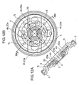
- a plurality of (in this modification, four) shaft-shaped protrusions 1j may be formed on the inner surface of the guide bracket 1 in such a manner as to come into contact with an outer peripheral surface of a circular plate 20 which is formed with a plurality of engagement holes 20a and a center hole 20b, and disposed between the guide bracket 1 and the internal gear member 2, as shown in FIGS. 12A and 12B .
- the rotatable cam 4 is formed with a plurality of (in this modification, four) shaft-shaped protrusions 4h.
- the protrusions 4h are inserted into the respective engagement holes 20a of the circular plate 20 to allow the circular plate 20 to be integrated with the rotatable cam 4.
- the operation member is inserted into the center hole 20b of the circular plate 20.
- the protrusions 1j are not necessarily arranged at even intervals. In this manner, the circular plate 20 integral with the rotatable cam 4 is fitted inside the protrusions 1j, so that the rotatable cam 4 can be stably rotated in its fitted state.
- the internal gear member and the guide bracket may be mounted, respectively, to the seat cushion and the seat back.
- the number of the lock gear members may be two or three or may be five or more.
- a seat reclining mechanism designed to be mounted to a seat cushion and a seat back so as to allow the seat back to be reclined.
- the seat reclining mechanism comprises: a guide bracket adapted to be mounted to either one of the seat cushion and the seat back; an internal gear member adapted to be mounted to a remaining one of the seat cushion and the seat back, wherein the internal gear member is coupled to the guide bracket in a rotatable manner about a rotation axis thereof with respect to the guide bracket, and formed with internal teeth along a circle having a center on the rotation axis; a plurality of lock gear members disposed between the guide bracket and the internal gear member to have a center on the rotation axis and extend radially in a spoke-like pattern, wherein each of the lock gear members is formed with external teeth meshingly engageable with the internal teeth, and supported by the guide bracket in such a manner as to be slidable in both a lock direction causing the external teeth to be brought into meshing engagement with the
- the stopper plate is designed to have the forwardmost-inclination stopper portion adapted to be brought into contact with the forwardmost-inclination stopper protrusion when the seat back is at the forwardmost inclined position, and the rearwardmost-inclination stopper portion adapted to be brought into contact with the rearwardmost-inclination stopper protrusion when the seat back is at the rearwardmost inclined position, so that a stopper can be incorporated in the reclining mechanism.
- This makes it possible to prevent an increase in outside dimension of a seat so as to provide enhanced flexibility of seat layout.
- a need for using a stopper member having a relatively large size, such as a stopper bracket can be eliminated to facilitate reductions in cost and weight of a seat.
- the forwardmost-inclination stopper protrusion and the rearwardmost-inclination stopper protrusion are formed on the one of the guide bracket and the internal gear member through a half blanking process.
- the forwardmost-inclination stopper protrusion and the rearwardmost-inclination stopper protrusion can be formed through a half blanking process to more facilitate the reduction in cost.
Landscapes
- Engineering & Computer Science (AREA)
- Aviation & Aerospace Engineering (AREA)
- Transportation (AREA)
- Mechanical Engineering (AREA)
- Chairs For Special Purposes, Such As Reclining Chairs (AREA)
Abstract
Description
- The present invention relates to a seat reclining mechanism.
- Heretofore, there has been known a seat reclining mechanism designed to be mounted to a seat cushion and a seat back so as to allow the seat back to be reclined.
JP 2001-17259A JP 2004-154585A - In this mechanism, when an operator operates an operation lever to rotate the rotatable cam in a direction opposite to the lock-causing rotation direction, the lock gear members are moved in the unlock direction through a circular lever (actuating plate), and released from the engagement with the internal gear member. Thus, the seat back can be forwardly or rearwardly inclined. Then, when the operator releases his/her hand from the operation lever, the rotatable cam is rotated in the lock-causing rotation direction by a biasing force of the lock spring, and the lock gear members are moved in the lock direction and brought into engagement with the internal gear member. Thus, the seat back is locked at an intended inclined position.
- In such a reclining mechanism, a stopper for positioning a seat back at a forwardmost inclined position or a rearwardmost inclined position typically comprises a structure adapted to allow a stopper bracket fixed to a back frame of the seat back to be brought into contact with a stopper portion of a seat cushion.
- Thus, in this conventional structure, the stopper is disposed to protrude outwardly from the reclining mechanism to cause an increase in outside dimension of a seat and impose restrictions on seat layout. Moreover, a need for using a stopper member having relatively large size, such as the stopper bracket, causes a problem about an increase in weight of a seat.
- In view of the above problem, it is an object of the present invention to provide a seat reclining mechanism capable of facilitating reductions in cost and weight while allowing downsizing and less restrictions on seat layout.
- In order to achieve this object, the present invention provides a seat reclining mechanism designed to be mounted to a seat cushion and a seat back so as to allow the seat back to be reclined. The seat reclining mechanism comprises: a guide bracket adapted to be mounted to either one of the seat cushion and the seat back; an internal gear member adapted to be mounted to a remaining one of the seat cushion and the seat back, wherein the internal gear member is coupled to the guide bracket in a rotatable manner about a rotation axis thereof with respect to the guide bracket, and formed with internal teeth along a circle having a center on the rotation axis; a plurality of lock gear members disposed between the guide bracket and the internal gear member to extend radially from the rotation axis, wherein each of the lock gear members is formed with external teeth meshingly engageable with the internal teeth, and supported by the guide bracket in such a manner as to be slidable in both a lock direction causing the external teeth to be brought into meshing engagement with the internal teeth and an unlock direction causing the external teeth to be released from the meshing engagement with the internal teeth; a rotatable cam rotatably supported by either one of the guide bracket and the internal gear member, and adapted to be rotatable in both a lock-causing rotation direction causing the lock gear members to be slidingly moved in the lock direction and an unlock-causing rotation direction causing the lock gear members to be slidingly moved in the unlock direction; a lock spring biasing the rotatable cam in the lock-causing rotation direction; a forwardmost-inclination stopper protrusion and a rearwardmost-inclination stopper protrusion which are provided on either one of the guide bracket and the internal gear member; and a stopper plate fixed to a remaining one of the guide bracket and the internal gear member, wherein the stopper plate has a forwardmost-inclination stopper portion adapted to be brought into contact with the forwardmost-inclination stopper protrusion when the seat back is at a forwardmost inclined position, and a rearwardmost-inclination stopper portion adapted to be brought into contact with the rearwardmost-inclination stopper protrusion when the seat back is at a rearwardmost inclined position.
-
-
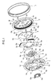
FIG. 1 is an exploded perspective view showing a reclining mechanism according to one embodiment of the present invention. -
FIG. 2A is a sectional view showing the mechanism, taken along the line IIA-IIA inFIG. 2B . -
FIG. 2B is a see-through front view showing the mechanism, when viewed from the side of an internal gear member. -
FIG 3A is a front view of a guide bracket in the mechanism, when viewed from the side of an inner surface thereof. -
FIG. 3B is a back view showing the guide bracket, when viewed from the side of an outer surface thereof. -
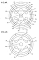
FIG. 4A is a front view showing the internal gear member in the mechanism, when viewed from the side of an inner surface thereof. -
FIG. 4B is a back view showing the internal gear member, when viewed from the side of an outer surface thereof. -
FIG. 5A is a front view showing a lock gear member having a protrusion, which is one of a plurality of lock gear members in the mechanism. -
FIG. 5B is a front view showing a lock gear member devoid of the protrusion, which is one of the plurality of lock gear members. -
FIG. 5C is a front view showing a rotatable cam in the mechanism. -
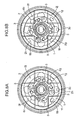
FIG. 6A is a see-through front view showing the mechanism, when viewed from the side of the internal gear member, in a state after a seat back is set at an initial locked position. -
FIG. 6B is a see-through front view showing the mechanism, when viewed from the side of the internal gear member, wherein the protrusion is located on a free-zone arc portion. -
FIG. 7A is a see-through front view showing the mechanism, when viewed from the side of the internal gear member, wherein a forwardmost-inclination stopper portion is in contact with a forwardmost-inclination stopper protrusion. -
FIG 7B is a see-through front view showing the mechanism, when viewed from the side of the internal gear member, wherein a rearwardmost-inclination stopper portion is in contact with a rearwardmost-inclination stopper protrusion. -
FIG. 8A is a see-through front view showing a reclining mechanism of a type designed to lock a seat back at a forwardmost inclined position, when viewed from the side of an internal gear member, in a state when the seat back is locked at the forwardmost inclined position. -
FIG. 8B is a see-through front view showing the mechanism inFIG 8A , when viewed from the side of the internal gear member, in a state when the seat back is locked at an initial locked position, e.g., an upright position. -
FIG. 9A is a see-through front view showing a reclining mechanism of a type designed to keep a seat back from being locked at a forwardmost inclined position, when viewed from the side of an internal gear member, in a state when the seat back is set at the forwardmost inclined position without being locked. -
FIG. 9B is a see-through front view showing the mechanism inFIG. 9A , when viewed from the side of an internal gear member, in a state when the seat back is locked at an initial locked position, e.g., an upright position. -
FIG. 10 is a local front view showing a reclining mechanism as a first modification of the embodiment illustrated inFIG. 1 -
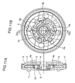
FIG. 11A is a sectional view showing a reclining mechanism as a second modification of the embodiment illustrated inFIG. 1 , taken along the line XIA-XIA inFIG. 11B . -
FIG. 11B is a see-through front view showing the mechanism as the second modification, when viewed from the side of an internal gear member. -
FIG. 12A is a sectional view showing a reclining mechanism as a third modification of the embodiment illustrated inFIG. 1 , taken along the line XIIA-XIIA inFIG. 12B . -
FIG. 12B is a see-through front view showing the mechanism as the third modification, when viewed from the side of an internal gear member. - With reference to the drawings, the present invention will now be specifically described based on a preferred embodiment thereof.
- As shown in
FIGS. 1 ,2A and 2B , a seat reclining mechanism according to one embodiment of the present invention is designed to be mounted to a seat cushion and a seat back of a seat so as to allow the seat back to be reclined. The mechanism comprises aguide bracket 1 adapted to be mounted to the seat cushion, aninternal gear member 2 adapted to be mounted to the seat back, fourlock gear members 3, arotatable cam 4, alock spring 5, astopper plate 6, and aring 7. - As shown in
FIGS. 3A and 3B , theguide bracket 1 is formed in a circular disk shape. Theguide bracket 1 has a fitting portion which comprises afitting hole 1a concentrically formed in theguide bracket 1. Thefitting hole 1a includes acutout 1b formed to lock anouter end 5a of thelock spring 5 which is a spiral spring. - The
guide bracket 1 has fourguide grooves 1c which are formed in an inner surface thereof through a half blanking process to extend from an inner peripheral edge of thefitting hole 1a in a radially outward direction of theguide bracket 1 in a spoke-like pattern. The fourguide grooves 1c are arranged to form a cross shape, and thefitting hole 1a is formed in a central region of theguide grooves 1c. The inner surface of theguide bracket 1 means a surface of theguide bracket 1 located in opposed relation to theinternal gear member 2. - Each of the
guide grooves 1c has a columnar-shapedconvex portion 1d formed through a half blanking process to protrude outwardly from an outer surface of theguide bracket 1. Theconvex portions 1d serve as a positioning means to be used when theguide bracket 1 is mounted to the seat cushion. - The
guide bracket 1 also has a semi-columnar-shaped forwardmost-inclination stopper protrusion 1f and a semi-columnar-shaped rearwardmost-inclination stopper protrusion 1g which are formed, respectively, in two regions defined between a horizontally-extending right one and a downwardly-extending one of the fourguide grooves 1c and between a horizontally-extending left one and the downwardly-extending one of the fourguide grooves 1c inFIG. 3A , to protrude inwardly from the inner surface theguide bracket 1. Thesestopper protrusions inclination stopper protrusion 1f and the rearwardmost-inclination stopper protrusion 1g are adapted to come into contact with thestopper plate 6 when the seat back is moved to a forwardmost inclined position and a rearwardmost inclined position, respectively, as will be described in detail later. - As shown in
FIGS. 4A and 4B , theinternal gear member 2 is formed in a circular disk shape. Theinternal gear member 2 is coupled to theguide bracket 1 in a rotatable manner about a rotation axis thereof with respect to theguide bracket 1. The center of theguide bracket 1 is located on the rotation axis of theinternal gear member 2. - The
internal gear member 2 has two steps of concave portions formed in an inner surface of thereof through a half blanking process. Two sidewalls constituting respective ones of the first-stepconcave portion 2k and the second-stepconcave portion 2m are formed, respectively, in a circular shape and a circular arc shape in front view. Each of the circular-shaped sidewall and the circular arc-shaped sidewall are formed in concentric relation with an after-mentioned through-hole 2a. The inner surface of theinternal gear member 2 means a surface of theinternal gear member 2 located in opposed relation to theguide bracket 1. - The sidewall of the first-step
concave portion 2k hasinternal teeth 2e formed over the entire inner peripheral surface thereof. Theinternal teeth 2e are formed through a half blanking process. - The second-step
concave portion 2m has abottom wall 2b formed with a through-hole 2a having a diameter less than that of thefitting hole 1a of theguide bracket 1, and six columnar-shapedconvex portions 2c each protruding outwardly from an outer surface of theinternal gear member 2, and fourlock protrusions 2d each protruding inwardly from the inner surface of theinternal gear member 2. The through-hole 2a has a center located on the rotation axis of theinternal gear member 2. Theconvex portions 2c serve as a positioning means to be used when theinternal gear member 2 is mounted to the seat back. Thelock protrusions 2d serve as a means to position and lock thestopper plate 6, as will be described in detail later. Each of theconvex portions 2c and thelock protrusions 2d are formed through a half blanking process. - The sidewall of the second-step
concave portion 2m is formed to have an inner peripheral surface which comprises a first free-zone arc portion 2f, a first lock-zone arc portion 2h, a second free-zone arc portion 2g, and a second lock-zone arc portion 2j. Each of thearc portions internal gear member 2. - The first free-
zone arc portion 2f is located in opposed relation to the second free-zone arc portion 2g, and the first and second free-zone arc portions zone arc portion 2h is located in opposed relation to the second lock-zone arc portion 2j, and the first and second lock-zone arc portions - The first free-
zone arc portion 2f has an arc length greater than that of the second free-zone arc portion 2g. That is, a center angle θ1 of the first free-zone arc portion 2f is greater than a center angle θ2 of the second free-zone arc portion 2g. Each of the free-zone arc portions zone arc portions - The free-
zone arc portions protrusion 3c of one of thelock gear members 3 to be in contact with either one thereof when thelock gear members 3 are located at a position where an after-mentionedexternal teeth 3a of thelock gear members 3 are not in meshing engagement with theinternal teeth 2e of theinternal gear member 2. Further, the lock-zone arc portions protrusion 3c to be in contact with either one thereof when thelock gear members 3 are located at a position where the after-mentionedexternal teeth 3a are in meshing engagement with theinternal teeth 2e. - As shown in
FIGS. 1 ,2A and 2B , the fourlock gear members 3 are disposed between theguide bracket 1 and theinternal gear member 2 to extend radially from the rotation axis in a cross-like pattern. That is, the four lock gear members are arranged at intervals of about 90 degrees. This provides enhanced stability and safety in a locked state. - As shown in
FIGS. 5A and 5B , each of thelock gear members 3 has an arc-shaped surface located in opposed relation to theinternal teeth 2e of theinternal gear member 2 and formed withexternal teeth 3a meshingly engageable with theinternal teeth 2e. Each of thelock gear members 3 is supported by a corresponding one of theguide grooves 1c of theguide bracket 1 in such a manner as to be slidable in both a lock direction R2 causing theexternal teeth 3a to be brought into meshing engagement with theinternal teeth 2e and an unlock direction U2 causing theexternal teeth 3a to be released from the meshing engagement with theinternal teeth 2e. - Each of the
lock gear members 3 has anengagement groove 3b formed on a leading side of the unlock direction U2 to allow a corresponding one of after-mentionedengagement pawls 4e of therotatable cam 4 to be brought into engagement therewith. Theengagement groove 3b is formed in a shape which allows the after-mentionedengagement pawl 4e to be inserted thereinto when therotatable cam 4 is rotated in an after-mentioned unlock-causing rotation direction U1. As shown inFIG. 5A , one of the fourlock gear members 3 has aprotrusion 3c protruding toward theinternal gear member 2. Theprotrusion 3c is formed through a half blanking process. - As shown in
FIGS. 1 ,2A and5C , therotatable cam 4 is rotatably supported by thefitting hole 1a of theguide bracket 1, and adapted to be rotatable in both a lock-causing rotation direction R1 and an unlock-causing rotation direction U1 illustrated inFIG. 5C . Therotatable cam 4 has acam body 4n, fourengagement pawls 4e protruding from thecam body 4n in the unlock-causing rotation direction U1, afitting boss 4c protruding from thecam body 4n toward theguide bracket 1, and a raisedportion 4m protruding from thefitting boss 4c toward theguide bracket 1. - The
rotatable cam 4 has two steps of recesses concaved toward theguide bracket 1, when viewed from the side of theinternal gear member 2. The recesses are formed through a half blanking process. Thefitting boss 4c is created by forming the first-step recess, and the raisedportion 4m is created by forming the second-step recess. - The
rotatable cam 4 has anelongate hole 4a formed in a central region thereof to have a shape close to an oval shape. Theelongate hole 4a is formed to penetrate through abottom wall 4b of the second-step recess. Each of thefitting boss 4c, the raisedportion 4m and theelongate hole 4a has a center located on the rotation axis of theinternal gear member 2. - The
fitting boss 4c has an annular-shapedboss body 4j, and fourprotrusions 4k which protrude radially from theboss body 4j toward an inner peripheral surface of thefitting hole 1a in a cross-like pattern, in such a manner that an outer peripheral surface of each of theprotrusions 4k comes into slide contact with the inner peripheral surface of thefitting hole 1a. In this manner, thefitting boss 4c is fitted in (roughly guided by) thefitting hole 1a under a condition that the respective outer peripheral surfaces of theprotrusions 4k are in contact with the inner peripheral surface of thefitting hole 1a. This provides a centering function to the reclining mechanism so as to prevent axial wobbling of therotatable cam 4 relative to thefitting hole 1a. - For example, if the
fitting boss 4c consists only of an annular-shaped boss body, the boss body (i.e., thefitting boss 4c) will be designed to have an outer diameter approximately equal to an inner diameter of thefitting hole 1a in which the boss body is fitted. In this case, the outer diameter of the boss body is necessarily set at a value less than an outer diameter of thecam body 4n. By contrast, when thefitting boss 4c comprises theboss body 4j and theprotrusions 4k, and each of the protrusions is formed to extend toward a root of a corresponding one of theengagement pawls 4e, as in this embodiment, the fitting boss has an outer diameter equal to a distance between the rotation axis and the outer peripheral surface of each of theprotrusions 4k, so that each of the outer diameter of thefitting boss 4c and the inner diameter of thefitting hole 1a can be set at a value greater than the outer diameter of thecam body 4n. This makes it possible to more stably rotate therotatable cam 4 in its fitted state. - The raised
portion 4m is formed with acutout 4d for locking aninner end 5b of thelock spring 5. Theouter end 5a of thelock spring 5 is locked by thecutout 1b of theguide bracket 1, as mentioned above. Thus, thelock spring 5 biases therotatable cam 4 in the lock-causing rotation direction R1. - An operation member, such as an operation rod connected to an operation lever or the like, penetrating through the
fitting hole 1a of theguide bracket 1 and the through-hole 2a of theinternal gear member 2, is fitted in theelongate hole 4a in a non-rotatable manner relative thereto. Thus, therotatable cam 4 can be rotated by the operation member. The operation member is not supported by theguide bracket 1 and theinternal gear member 2. - The four
engagement pawls 4e are formed to protrude in a direction approximately tangential to a circle having a center on the rotation axis of theinternal gear member 2, and arranged at approximately even intervals. - As shown in
FIGS. 5A, 5B and 5C , when therotatable cam 4 is rotated in the lock-causing rotation direction R1, theengagement pawls 4e push respective outside walls 3b2 of theengagement grooves 3b in the lock direction R2. Thus, thelock gear members 3 are slidingly moved in the lock direction R2, so that theexternal teeth 3a of thelock gear members 3 are brought into meshing engagement with theinternal teeth 2e of the internal gear member 2 (seeFIG. 6A ). - When the
rotatable cam 4 is rotated in the unlock-causing rotation direction U1, theengagement pawls 4e are brought into engagement with therespective engagement grooves 3b to pull respective inside walls 3b1 of theengagement grooves 3b in the unlock direction U2. Thus, thelock gear members 3 are slidingly moved in the unlock direction U2, so that theexternal teeth 3a of thelock gear members 3 are moved apart from theinternal teeth 2e of theinternal gear member 2 to release the meshing engagement between theexternal teeth 3a and theinternal teeth 2e (seeFIGS. 2B and6B ). - As shown in
FIGS. 1 ,7A and 7B , thestopper plate 6 is formed with fourcatch holes 6a engageable with therespective lock protrusions 2d provided on the inner surface of theinternal gear member 2. Thus, thestopper plate 6 is positioned and locked relative to theinternal gear member 2. Thestopper plate 6 has a forwardmost-inclination stopper portion 6b (seeFIG. 7A ) adapted to be brought into contact with the forwardmost-inclination stopper protrusion 1f of theguide bracket 1 when the seat back is moved to a forwardmost inclined position, and a rearwardmost-inclination stopper portion 6c (seeFIG 7B ) adapted to be brought into the rearwardmost-inclination stopper protrusion 1g of theguide bracket 1 when the seat back is moved to a rearwardmost inclined position. Thestopper portions plate body 6d of thestopper plate 6. - As above, the forwardmost-
inclination stopper protrusion 1f and the rearwardmost-inclination stopper protrusion 1g are formed in theguide bracket 1, and thestopper plate 6 is fixed to theinternal gear member 2, so that a stopper can be incorporated in the reclining mechanism. This makes it possible to prevent an increase in outside dimension of a seat so as to provide enhanced flexibility of seat layout. In addition, a need for a large-size stopper bracket can be eliminated to facilitate a reduction in weight of a seat. - The forwardmost-
inclination stopper protrusion 1f and the rearwardmost-inclination stopper protrusion 1g are formed in theguide bracket 1 through a half blanking process to facilitate a reduction in cost. It is understood that each of the forwardmost-inclination stopper protrusion 1f and the rearwardmost-inclination stopper protrusion 1g may be prepared as a separate component. In this case, thestopper protrusions guide bracket 1 or theinternal gear member 2 after preparing theguide bracket 1 or theinternal gear member 2, so that a stopper position can be readily changed in the event of design changes for a configuration or mounting position of a reclining mechanism. - The
ring 7 is fitted on an outer periphery of theguide bracket 1 and theinternal gear member 2 after thelock gear members 3, therotatable cam 4, thestopper plate 6 are installed between theguide bracket 1 and theinternal gear member 2. In this manner, the reclining mechanism is unitized. Thelock spring 5 can be installed from thefitting hole 1a of theguide bracket 1 to allow theouter end 5a and theinner end 5b to be locked by thecutout 1b of theguide bracket 1 and thecutout 4d of therotatable cam 4, respectively. - In a process of assembling the unitized reclining mechanism to a seat, the
guide bracket 1 is mounted to a seat cushion, and theinternal gear member 2 is mounted to a seat back. Then, an operation member, such as an operation rod connected to an operation lever or the like, is inserted from thefitting hole 1a of theguide bracket 1, and fitted in theelongate hole 4a of therotatable cam 4 in a non-rotatable manner relative thereto. - A relationship between respective ones of the
rotatable cam 4, thelock gear members 3, and thearc portions internal gear member 2, will be described below. - Before the
lock gear members 3 are brought into meshing engagement with theinternal gear member 2, theprotrusion 3c of one of thelock gear members 3 is brought into contact with either one of the free-zone arc portions protrusion 3c is brought into contact with either one of the free-zone arc portions lock gear members 3 are restrained, and thereby an unlocked state (lock-released state) is maintained. - The first free-
zone arc portion 2f is used for a reclining mechanism of a "type designed to keep a seat back from being locked at a forwardmost inclined position". The second free-zone arc portion 2g is used for a reclining mechanism of a "type designed to lock a seat back at a forwardmost inclined position". - As shown in
FIG. 4A , the first free-zone arc portion 2f has a center angle greater than that of the second free-zone arc portion 2g. For example, the center angle θ1 of the first free-zone arc portion 2f is set at 106 degree, and the center angle θ2 of the second free-zone arc portion 2g is set at 90 degree. - In a conventional seat reclining mechanism, an internal gear member is formed with only either one of the free-zone arc portions. Differently, in this embodiment, the
internal gear member 2 is formed with both the first free-zone arc portion 2f and the second free-zone arc portion 2g. - Thus, in an operation of installing the
lock gear members 3 between theguide bracket 1 and theinternal gear member 2, an installation position of theprotrusion 3c of one of thelock gear members 3 can be selected such that either one of the first free-zone arc portion 2f and the second free-zone arc portion 2g of theinternal gear member 2 is located relative to theprotrusion 3c. Thus, in this embodiment using theinternal gear member 2, the installation position of theprotrusion 3c can be changed to select either one of the type designed to keep a seat back from being locked at a forwardmost inclined position (i.e., lock free type), and the type designed to lock a seat back at a forwardmost inclined position. This makes it possible to facilitate a reduction in cost of the reclining mechanism. -
FIGS. 8A and 8B are front views showing the reclining mechanism set as the type designed to lock a seat back at a forwardmost inclined position, whereinFIG. 8A shows the reclining mechanism in a state when the seat back is at the forwardmost inclined position, andFIG. 8B shows the reclining mechanism in a state when the seat back is at an initial locked position (e.g., upright position) where it is initially locked after being inclined rearwardly from the forwardmost inclined position. - In this type, as the seat back is inclined forwardly from a rearwardly inclined position, for example, from the state illustrated in
FIG. 6B , theinternal gear member 2 is rotated in a counterclockwise direction inFIG. 6B , and one edge of the second free-zone arc portion 2g is moved beyond theprotrusion 3c to allow theprotrusion 3c to be placed on the first lock-zone arc portion 2h. In conjunction with this movement, the restraint on movement of thelock gear members 3 in the lock direction R2 is released, and thereby thelock gear members 3 are slidingly moved in the lock direction R2 to allow theexternal teeth 3a to be brought into meshing engagement with theinternal teeth 2e. Thus, the seat back is locked at the forwardmost inclined position (the state illustrated inFIG. 8A ). In this state, the forwardmost-inclination stopper portion 6b of thestopper plate 6 is in contact with the forwardmost-inclination stopper protrusion 1f of theguide bracket 1. - In an operation of inclining the seat back locked at the forwardmost inclined position rearwardly, the
rotatable cam 4 is rotated in the unlock-causing rotation direction U1 using the operation member to allow theengagement pawls 4e of therotatable cam 4 to be brought into engagement with therespective engagement grooves 3b of thelock gear members 3. Thus, thelock gear members 3 are slidingly moved along therespective guide grooves 1c in the unlock direction U2, and thereby the meshing engagement between theexternal teeth 3a and theinternal teeth 2e is released, i.e., the locked state is released. Consequently, theinternal gear member 2 becomes rotatable relative to theguide bracket 1. - In this lock-released state, when the seat back is inclined rearwardly, the
protrusion 3c placed on the first lock-zone arc portion 2h is moved in such a manner as to be placed on the second free-zone arc portion 2g (the state illustrated inFIG. 6B ). In the state when theprotrusion 3c is in contact with the second free-zone arc portion 2g, as shown inFIG. 6B , the movement of thelock gear members 3 in the lock direction R2 is restrained. Thus, the seat back can be freely inclined rearwardly or forwardly. - The seat back is further inclined rearwardly from the state illustrated in
FIG. 6B , the other edge of the second free-zone arc portion 2g is moved beyond theprotrusion 3c to allow theprotrusion 3c to be placed on the second lock-zone arc portion 2j. In conjunction with this movement, the restraint on movement of thelock gear members 3 in the lock direction R2 is released, and thereby thelock gear members 3 are slidingly moved in the lock direction R2 to allow theexternal teeth 3a to be brought into meshing engagement with theinternal teeth 2e. Thus, the seat back is locked at the initial locked position (e.g., upright position) (the state illustrated inFIG. 8B ). - The seat back can be further inclined from the initial locked position illustrated in
FIG. 8B up to a rearwardmost inclined position illustrated inFIG 7B . During movement from the initial locked position to the rearwardmost inclined position, theprotrusion 3c is placed on the second lock-zone arc portion 2j, and thereby theexternal teeth 3a is in meshing engagement with theinternal teeth 2e, i.e., the reclining mechanism is in the locked state. Thus, in an operation of inclining the seat back rearwardly from the initial locked position to the rearwardmost inclined position, therotatable cam 4 is rotated in the unlock-causing rotation direction U1 using the operation member so as to slidingly move thelock gear members 3 in the unlock direction U2 to release the locked state, and then the seat back is inclined rearwardly. - When the seat back reaches the rearwardmost inclined position, the rearwardmost-
inclination stopper portion 6c of thestopper plate 6 is brought into contact with the rearwardmost-inclination stopper protrusion 1g of theguide bracket 1. -
FIGS. 9A and 9B are front views showing the reclining mechanism set as the type designed to keep the seat back from being locked at the forwardmost inclined position, whereinFIG 9A shows the reclining mechanism in a state when the seat back is at the forwardmost inclined position, andFIG 9B shows the reclining mechanism in a state when the seat back is at the initial locked position (e.g., upright position) where it is initially locked after being inclined rearwardly from the forwardmost inclined position. - In this type, the first free-
zone arc portion 2f having an arc length greater than that of the second free-zone arc portion 2g is used. As the seat back is inclined forwardly from a rearwardly inclined position, theinternal gear member 2 is rotated. Then, when the seat back reaches the forwardmost inclined position (the state illustrated inFIG. 9A ), theprotrusion 3c is still placed on the first free-zone arc portion 2f. Thus, in this type, the seat back is not locked at the forwardmost inclined position. The remaining operations are the same as those in the type designed to lock the seat back at the forwardmost inclined position, and their description will be omitted. - In the reclining mechanism according to the above embodiment, the
fitting boss 4c formed on therotatable cam 4 is fitted in thefitting hole 1a formed in theguide bracket 1. Alternatively, as shown inFIG. 10 , therotatable cam 4 may be configured to have a plurality of (in this modification, four) shaft-shapedprotrusions 4g formed at positions to be in contact with the inner peripheral surface of thefitting hole 1a, wherein theprotrusions 4g are fitted in thefitting hole 1a. In this case, as long as each of theprotrusions 4g is located on a common circle having a center on a rotation axis of the rotatable cam 4 (i.e., on the rotation axis of the internal gear member 2), theprotrusions 4g are not necessarily arranged at even intervals. Alternatively, in place of the plurality of protrusions, a disk-shaped raised portion having an outer peripheral surface fittable in the inner peripheral surface of thefitting hole 1a as indicated by the two-dot chain line inFIG 10 may be formed, wherein the raised portion is fitted in thefitting hole 1a. - In place of the structure adapted to be fitted in the
fitting hole 1a, arecess 1h adapted to come into circumscribing contact with theengagement pawls 4e of therotatable cam 4 may be formed in the inner surface of theguide bracket 1, wherein respective outer peripheral portions of theengagement pawls 4e of therotatable cam 4 are fitted in an inner peripheral surface of therecess 1h, as shown inFIGS. 11A and 11B . In this manner, an outer peripheral portion of therotatable cam 4 is fitted in thefitting recess 1h, so that therotatable cam 4 can be stably rotated in its fitted state. - Further, in place of the structure adapted to be fitted in the
fitting hole 1a, a plurality of (in this modification, four) shaft-shapedprotrusions 1j may be formed on the inner surface of theguide bracket 1 in such a manner as to come into contact with an outer peripheral surface of acircular plate 20 which is formed with a plurality ofengagement holes 20a and acenter hole 20b, and disposed between theguide bracket 1 and theinternal gear member 2, as shown inFIGS. 12A and 12B . In this case, therotatable cam 4 is formed with a plurality of (in this modification, four) shaft-shapedprotrusions 4h. Theprotrusions 4h are inserted into therespective engagement holes 20a of thecircular plate 20 to allow thecircular plate 20 to be integrated with therotatable cam 4. The operation member is inserted into thecenter hole 20b of thecircular plate 20. As long as each of theprotrusions 1j is located on a circle concentric with thecircular plate 20, theprotrusions 1j are not necessarily arranged at even intervals. In this manner, thecircular plate 20 integral with therotatable cam 4 is fitted inside theprotrusions 1j, so that therotatable cam 4 can be stably rotated in its fitted state. - While the above embodiment has been described based on one example where the guide bracket and the internal gear member are mounted, respectively, to the seat cushion and the seat back, the internal gear member and the guide bracket may be mounted, respectively, to the seat cushion and the seat back.
- Further, while the above embodiment has been described based on one example where the four lock gear members are arranged, the number of the lock gear members may be two or three or may be five or more.
- The above embodiment may be summarized as follows.
- According to one aspect of the present invention, there is provided a seat reclining mechanism designed to be mounted to a seat cushion and a seat back so as to allow the seat back to be reclined. The seat reclining mechanism comprises: a guide bracket adapted to be mounted to either one of the seat cushion and the seat back; an internal gear member adapted to be mounted to a remaining one of the seat cushion and the seat back, wherein the internal gear member is coupled to the guide bracket in a rotatable manner about a rotation axis thereof with respect to the guide bracket, and formed with internal teeth along a circle having a center on the rotation axis; a plurality of lock gear members disposed between the guide bracket and the internal gear member to have a center on the rotation axis and extend radially in a spoke-like pattern, wherein each of the lock gear members is formed with external teeth meshingly engageable with the internal teeth, and supported by the guide bracket in such a manner as to be slidable in both a lock direction causing the external teeth to be brought into meshing engagement with the internal teeth and an unlock direction causing the external teeth to be released from the meshing engagement with the internal teeth; a rotatable cam rotatably supported by either one of the guide bracket and the internal gear member, and adapted to be rotatable in both a lock-causing rotation direction causing the lock gear members to be slidingly moved in the lock direction and an unlock-causing rotation direction causing the lock gear members to be slidingly moved in the unlock direction; a lock spring biasing the rotatable cam in the lock-causing rotation direction; a forwardmost-inclination stopper protrusion and a rearwardmost-inclination stopper protrusion which are provided on either one of the guide bracket and the internal gear member; and a stopper plate fixed to a remaining one of the guide bracket and the internal gear member, wherein the stopper plate has a forwardmost-inclination stopper portion adapted to be brought into contact with the forwardmost-inclination stopper protrusion when the seat back is at a forwardmost inclined position, and a rearwardmost-inclination stopper portion adapted to be brought into contact with the rearwardmost-inclination stopper protrusion when the seat back is at a rearwardmost inclined position.
- In the seat reclining mechanism of the aspect of the present invention, the stopper plate is designed to have the forwardmost-inclination stopper portion adapted to be brought into contact with the forwardmost-inclination stopper protrusion when the seat back is at the forwardmost inclined position, and the rearwardmost-inclination stopper portion adapted to be brought into contact with the rearwardmost-inclination stopper protrusion when the seat back is at the rearwardmost inclined position, so that a stopper can be incorporated in the reclining mechanism. This makes it possible to prevent an increase in outside dimension of a seat so as to provide enhanced flexibility of seat layout. In addition, a need for using a stopper member having a relatively large size, such as a stopper bracket, can be eliminated to facilitate reductions in cost and weight of a seat.
- Preferably, the forwardmost-inclination stopper protrusion and the rearwardmost-inclination stopper protrusion are formed on the one of the guide bracket and the internal gear member through a half blanking process.
- In this case, the forwardmost-inclination stopper protrusion and the rearwardmost-inclination stopper protrusion can be formed through a half blanking process to more facilitate the reduction in cost.
Claims (2)
- A seat reclining mechanism designed to be mounted to a seat cushion and a seat back so as to allow said seat back to be reclined, said seat reclining mechanism comprising:a guide bracket adapted to be mounted to either one of said seat cushion and said seat back;an internal gear member adapted to be mounted to a remaining one of said seat cushion and said seat back, said internal gear member being coupled to said guide bracket in a rotatable manner about a rotation axis thereof with respect to said guide bracket, and formed with internal teeth along a circle having a center on said rotation axis;a plurality of lock gear members disposed between said guide bracket and said internal gear member to extend radially from said rotation axis, each of said lock gear members being formed with external teeth meshingly engageable with said internal teeth, and supported by said guide bracket in such a manner as to be slidable in both a lock direction causing said external teeth to be brought into meshing engagement with said internal teeth and an unlock direction causing said external teeth to be released from the meshing engagement with said internal teeth;a rotatable cam rotatably supported by either one of said guide bracket and said internal gear member, and adapted to be rotatable in both a lock-causing rotation direction causing said lock gear members to be slidingly moved in said lock direction and an unlock-causing rotation direction causing said lock gear members to be slidingly moved in said unlock direction;a lock spring biasing said rotatable cam in said lock-causing rotation direction;a forwardmost-inclination stopper protrusion and a rearwardmost-inclination stopper protrusion which are provided on either one of said guide bracket and said internal gear member; anda stopper plate fixed to a remaining one of said guide bracket and said internal gear member, said stopper plate having a forwardmost-inclination stopper portion adapted to be brought into contact with said forwardmost-inclination stopper protrusion when said seat back is at a forwardmost inclined position, and a rearwardmost-inclination stopper portion adapted to be brought into contact with said rearwardmost-inclination stopper protrusion when said seat back is at a rearwardmost inclined position.
- The seat reclining mechanism as defined in claim 1, wherein said forwardmost-inclination stopper protrusion and said rearwardmost-inclination stopper protrusion are formed on said one of said guide bracket and said internal gear member through a half blanking process.
Applications Claiming Priority (1)
| Application Number | Priority Date | Filing Date | Title |
|---|---|---|---|
| JP2008095218A JP5220462B2 (en) | 2008-04-01 | 2008-04-01 | Seat reclining device |
Publications (2)
| Publication Number | Publication Date |
|---|---|
| EP2106723A1 true EP2106723A1 (en) | 2009-10-07 |
| EP2106723B1 EP2106723B1 (en) | 2010-11-17 |
Family
ID=39967756
Family Applications (1)
| Application Number | Title | Priority Date | Filing Date |
|---|---|---|---|
| EP08016224A Ceased EP2106723B1 (en) | 2008-04-01 | 2008-09-15 | Seat reclining mechanism |
Country Status (5)
| Country | Link |
|---|---|
| US (1) | US7802849B2 (en) |
| EP (1) | EP2106723B1 (en) |
| JP (1) | JP5220462B2 (en) |
| CN (1) | CN101548826B (en) |
| DE (1) | DE602008003521D1 (en) |
Cited By (3)
| Publication number | Priority date | Publication date | Assignee | Title |
|---|---|---|---|---|
| WO2011094478A1 (en) | 2010-01-29 | 2011-08-04 | Johnson Controls Technology Company | Recliner mechanism |
| FR3018051A1 (en) * | 2014-03-03 | 2015-09-04 | Faurecia Sieges Automobile | ARTICULATION MECHANISM AND VEHICLE SEAT COMPRISING SUCH A MECHANISM |
| EP3348437A4 (en) * | 2015-09-13 | 2019-05-01 | Delta Kogyo Co., Ltd. | SEAT INCLINATION DEVICE AND SEAT |
Families Citing this family (20)
| Publication number | Priority date | Publication date | Assignee | Title |
|---|---|---|---|---|
| JP2009072413A (en) * | 2007-09-21 | 2009-04-09 | Aisin Seiki Co Ltd | Vehicle seat reclining device |
| WO2009091980A1 (en) * | 2008-01-17 | 2009-07-23 | Fisher Dynamics Corporation | Round recliner mechanism |
| JP5318484B2 (en) * | 2008-07-29 | 2013-10-16 | 富士機工株式会社 | Vehicle seat reclining device |
| DE102009032750B4 (en) * | 2009-07-09 | 2021-08-26 | Adient Luxembourg Holding S.À R.L. | Fitting for a vehicle seat and vehicle seat with such a fitting |
| JP5593681B2 (en) * | 2009-11-17 | 2014-09-24 | アイシン精機株式会社 | Seat reclining device |
| US8507192B2 (en) * | 2010-02-18 | 2013-08-13 | Az Electronic Materials Usa Corp. | Antireflective compositions and methods of using same |
| DE112010005867T5 (en) * | 2010-10-15 | 2013-07-04 | Imasen Electric Industrial Co., Ltd. | vehicle seat |
| DE102010062932A1 (en) * | 2010-12-13 | 2012-06-14 | Brose Fahrzeugteile Gmbh & Co. Kommanditgesellschaft, Coburg | Resting binder for pivotally connecting two vehicle parts with each other, has fitting part and another fitting part that is mounted on former fitting part around rotating axis |
| JP5434968B2 (en) * | 2011-06-13 | 2014-03-05 | アイシン精機株式会社 | Vehicle seat reclining device |
| WO2013033829A1 (en) | 2011-09-08 | 2013-03-14 | Magna Seating Inc. | Quick adjust continuously engaged recliner |
| US20130076094A1 (en) * | 2011-09-27 | 2013-03-28 | Imasen Electric Industrial Co., Ltd. | Reclining apparatus |
| JP5969873B2 (en) * | 2012-09-27 | 2016-08-17 | 富士機工株式会社 | Vehicle seat reclining device |
| US9296315B2 (en) | 2013-02-26 | 2016-03-29 | Fisher & Company, Incorporated | Recliner mechanism with backdriving feature |
| US9902297B2 (en) | 2014-06-11 | 2018-02-27 | Fisher & Company, Incorporated | Latch mechanism with locking feature |
| JP6488746B2 (en) * | 2015-02-10 | 2019-03-27 | アイシン精機株式会社 | Vehicle seat reclining device |
| CN105691250A (en) * | 2016-01-18 | 2016-06-22 | 江苏忠明祥和精工股份有限公司 | Angle adjuster for automobile seat |
| CN105459858A (en) * | 2016-01-18 | 2016-04-06 | 江苏忠明祥和精工股份有限公司 | Automobile seat angle adjuster |
| JP6682300B2 (en) * | 2016-03-04 | 2020-04-15 | シロキ工業株式会社 | Seat reclining device |
| US10611273B2 (en) * | 2017-10-09 | 2020-04-07 | Faurecia Automotive Seating, Llc | Recliner system for a vehicle seat |
| CN111231796B (en) * | 2019-09-09 | 2022-05-17 | 佛吉亚(中国)投资有限公司 | Automobile seat and electric actuator thereof |
Citations (5)
| Publication number | Priority date | Publication date | Assignee | Title |
|---|---|---|---|---|
| EP0691238A1 (en) * | 1994-07-05 | 1996-01-10 | Cesa Compagnie Europeenne De Sieges Pour Automobiles | Articulation with adjusting position memory for seats |
| DE19918864A1 (en) * | 1998-04-27 | 1999-10-28 | Faure Bertrand Equipements Sa | Joint mechanism for motor vehicle seats |
| FR2841111A1 (en) * | 2002-06-19 | 2003-12-26 | Aisin Seiki | SEAT TILT DEVICE |
| US20050035640A1 (en) * | 2002-11-27 | 2005-02-17 | Katsuhiko Shinozaki | Recliner means and vehicle seat provided with the recliner means |
| JP2005186646A (en) * | 2003-12-24 | 2005-07-14 | Delta Kogyo Co Ltd | Seat reclining device |
Family Cites Families (13)
| Publication number | Priority date | Publication date | Assignee | Title |
|---|---|---|---|---|
| JP3308408B2 (en) * | 1994-10-31 | 2002-07-29 | 株式会社タチエス | Seat reclining device |
| FR2739812B1 (en) * | 1995-10-17 | 1998-03-27 | Cesa | ARTICULATION FOR A SEAT, AND A SEAT FOR A MOTOR VEHICLE PROVIDED WITH THIS ARTICULATION |
| JP2001017259A (en) | 1999-07-09 | 2001-01-23 | Delta Kogyo Co Ltd | Recliner unlocking structure |
| GB0024840D0 (en) * | 2000-10-10 | 2000-11-22 | Rodd Engineering Ltd | Chair tilting mechanism and a chair incorporating such a mechanism |
| JP3952900B2 (en) * | 2001-10-12 | 2007-08-01 | トヨタ紡織株式会社 | Reclining device |
| JP4595256B2 (en) * | 2001-06-26 | 2010-12-08 | アイシン精機株式会社 | Seat reclining device |
| JP4596694B2 (en) * | 2001-07-09 | 2010-12-08 | 株式会社今仙電機製作所 | Reclining device |
| JP3979132B2 (en) * | 2002-03-13 | 2007-09-19 | トヨタ紡織株式会社 | Setting method of sliding clearance in reclining device |
| JP4149739B2 (en) * | 2002-06-03 | 2008-09-17 | シロキ工業株式会社 | Reclining device ratchet and method of manufacturing the same |
| JP2004154585A (en) | 2003-12-25 | 2004-06-03 | Delta Kogyo Co Ltd | Bias structure of operation lever in reclining seat |
| JP4916155B2 (en) * | 2004-12-28 | 2012-04-11 | デルタ工業株式会社 | Reclining device |
| JP2008295695A (en) * | 2007-05-31 | 2008-12-11 | Fuji Kiko Co Ltd | Seat reclining device |
| US7703852B2 (en) * | 2007-12-03 | 2010-04-27 | Lear Corporation | Heavy duty reclining mechanism for vehicle seats |
-
2008
- 2008-04-01 JP JP2008095218A patent/JP5220462B2/en not_active Expired - Fee Related
- 2008-09-12 US US12/209,234 patent/US7802849B2/en not_active Expired - Fee Related
- 2008-09-15 DE DE602008003521T patent/DE602008003521D1/en active Active
- 2008-09-15 EP EP08016224A patent/EP2106723B1/en not_active Ceased
- 2008-09-17 CN CN2008101490252A patent/CN101548826B/en not_active Expired - Fee Related
Patent Citations (5)
| Publication number | Priority date | Publication date | Assignee | Title |
|---|---|---|---|---|
| EP0691238A1 (en) * | 1994-07-05 | 1996-01-10 | Cesa Compagnie Europeenne De Sieges Pour Automobiles | Articulation with adjusting position memory for seats |
| DE19918864A1 (en) * | 1998-04-27 | 1999-10-28 | Faure Bertrand Equipements Sa | Joint mechanism for motor vehicle seats |
| FR2841111A1 (en) * | 2002-06-19 | 2003-12-26 | Aisin Seiki | SEAT TILT DEVICE |
| US20050035640A1 (en) * | 2002-11-27 | 2005-02-17 | Katsuhiko Shinozaki | Recliner means and vehicle seat provided with the recliner means |
| JP2005186646A (en) * | 2003-12-24 | 2005-07-14 | Delta Kogyo Co Ltd | Seat reclining device |
Cited By (5)
| Publication number | Priority date | Publication date | Assignee | Title |
|---|---|---|---|---|
| WO2011094478A1 (en) | 2010-01-29 | 2011-08-04 | Johnson Controls Technology Company | Recliner mechanism |
| EP2528770A4 (en) * | 2010-01-29 | 2018-03-07 | Johnson Controls Technology Company | Recliner mechanism |
| FR3018051A1 (en) * | 2014-03-03 | 2015-09-04 | Faurecia Sieges Automobile | ARTICULATION MECHANISM AND VEHICLE SEAT COMPRISING SUCH A MECHANISM |
| US9527410B2 (en) | 2014-03-03 | 2016-12-27 | Faurecia Sieges D'automobiles | Hinge mechanism and vehicle seat comprising such a mechanism |
| EP3348437A4 (en) * | 2015-09-13 | 2019-05-01 | Delta Kogyo Co., Ltd. | SEAT INCLINATION DEVICE AND SEAT |
Also Published As
| Publication number | Publication date |
|---|---|
| US20090243361A1 (en) | 2009-10-01 |
| JP5220462B2 (en) | 2013-06-26 |
| CN101548826A (en) | 2009-10-07 |
| JP2009247395A (en) | 2009-10-29 |
| US7802849B2 (en) | 2010-09-28 |
| EP2106723B1 (en) | 2010-11-17 |
| DE602008003521D1 (en) | 2010-12-30 |
| CN101548826B (en) | 2013-02-13 |
Similar Documents
| Publication | Publication Date | Title |
|---|---|---|
| EP2106723B1 (en) | Seat reclining mechanism | |
| EP2106724B1 (en) | Seat reclining mechanism | |
| EP2106960B1 (en) | Seat reclining mechanism | |
| EP2106961A1 (en) | Seat reclining mechanism | |
| CN101925485B (en) | Full memory I-disk | |
| US6669296B2 (en) | Seat reclining device | |
| US6626495B2 (en) | Seat reclining device | |
| EP1674332B1 (en) | Vehicle seat reclining apparatus | |
| US8926018B2 (en) | Reclining apparatus | |
| JP4998867B2 (en) | Reclining adjuster | |
| US20130161994A1 (en) | Reclining apparatus | |
| US9108545B2 (en) | Reclining apparatus | |
| JP5540532B2 (en) | Vehicle seat coupling device | |
| JP3989283B2 (en) | Reclining mechanism | |
| JP5453852B2 (en) | Vehicle seat coupling device | |
| JP5817436B2 (en) | Reclining device | |
| JP2012011165A (en) | Reclining device | |
| JP2010227333A (en) | Connecting device of vehicle seat | |
| JP2007151728A (en) | Reclining device | |
| JP2010227332A (en) | Connecting device of vehicle seat | |
| MXPA01000984A (en) | A recliner assembly | |
| JPH08317829A (en) | Seat reclining device |
Legal Events
| Date | Code | Title | Description |
|---|---|---|---|
| PUAI | Public reference made under article 153(3) epc to a published international application that has entered the european phase |
Free format text: ORIGINAL CODE: 0009012 |
|
| AK | Designated contracting states |
Kind code of ref document: A1 Designated state(s): AT BE BG CH CY CZ DE DK EE ES FI FR GB GR HR HU IE IS IT LI LT LU LV MC MT NL NO PL PT RO SE SI SK TR |
|
| AX | Request for extension of the european patent |
Extension state: AL BA MK RS |
|
| 17P | Request for examination filed |
Effective date: 20100225 |
|
| GRAP | Despatch of communication of intention to grant a patent |
Free format text: ORIGINAL CODE: EPIDOSNIGR1 |
|
| AKX | Designation fees paid |
Designated state(s): DE FR GB |
|
| GRAS | Grant fee paid |
Free format text: ORIGINAL CODE: EPIDOSNIGR3 |
|
| GRAA | (expected) grant |
Free format text: ORIGINAL CODE: 0009210 |
|
| AK | Designated contracting states |
Kind code of ref document: B1 Designated state(s): DE FR GB |
|
| REG | Reference to a national code |
Ref country code: GB Ref legal event code: FG4D |
|
| REF | Corresponds to: |
Ref document number: 602008003521 Country of ref document: DE Date of ref document: 20101230 Kind code of ref document: P |
|
| PLBE | No opposition filed within time limit |
Free format text: ORIGINAL CODE: 0009261 |
|
| STAA | Information on the status of an ep patent application or granted ep patent |
Free format text: STATUS: NO OPPOSITION FILED WITHIN TIME LIMIT |
|
| 26N | No opposition filed |
Effective date: 20110818 |
|
| REG | Reference to a national code |
Ref country code: DE Ref legal event code: R097 Ref document number: 602008003521 Country of ref document: DE Effective date: 20110818 |
|
| REG | Reference to a national code |
Ref country code: FR Ref legal event code: PLFP Year of fee payment: 9 |
|
| REG | Reference to a national code |
Ref country code: FR Ref legal event code: PLFP Year of fee payment: 10 |
|
| REG | Reference to a national code |
Ref country code: FR Ref legal event code: PLFP Year of fee payment: 11 |
|
| PGFP | Annual fee paid to national office [announced via postgrant information from national office to epo] |
Ref country code: GB Payment date: 20180813 Year of fee payment: 11 |
|
| GBPC | Gb: european patent ceased through non-payment of renewal fee |
Effective date: 20190915 |
|
| PG25 | Lapsed in a contracting state [announced via postgrant information from national office to epo] |
Ref country code: GB Free format text: LAPSE BECAUSE OF NON-PAYMENT OF DUE FEES Effective date: 20190915 |
|
| PGFP | Annual fee paid to national office [announced via postgrant information from national office to epo] |
Ref country code: DE Payment date: 20200929 Year of fee payment: 13 Ref country code: FR Payment date: 20200928 Year of fee payment: 13 |
|
| REG | Reference to a national code |
Ref country code: DE Ref legal event code: R119 Ref document number: 602008003521 Country of ref document: DE |
|
| PG25 | Lapsed in a contracting state [announced via postgrant information from national office to epo] |
Ref country code: FR Free format text: LAPSE BECAUSE OF NON-PAYMENT OF DUE FEES Effective date: 20210930 Ref country code: DE Free format text: LAPSE BECAUSE OF NON-PAYMENT OF DUE FEES Effective date: 20220401 |