EP2106594B1 - Verfahren zur hervorhebung von unterschieden der grafischen erscheinung zwischen einem originaldokument und einem modifizierten dokument mit anmerkungen - Google Patents
Verfahren zur hervorhebung von unterschieden der grafischen erscheinung zwischen einem originaldokument und einem modifizierten dokument mit anmerkungen Download PDFInfo
- Publication number
- EP2106594B1 EP2106594B1 EP08724584.1A EP08724584A EP2106594B1 EP 2106594 B1 EP2106594 B1 EP 2106594B1 EP 08724584 A EP08724584 A EP 08724584A EP 2106594 B1 EP2106594 B1 EP 2106594B1
- Authority
- EP
- European Patent Office
- Prior art keywords
- vertices
- polygon
- polygon vertices
- document
- annotation
- Prior art date
- Legal status (The legal status is an assumption and is not a legal conclusion. Google has not performed a legal analysis and makes no representation as to the accuracy of the status listed.)
- Active
Links
Images


Classifications
-
- G—PHYSICS
- G06—COMPUTING OR CALCULATING; COUNTING
- G06T—IMAGE DATA PROCESSING OR GENERATION, IN GENERAL
- G06T11/00—2D [Two Dimensional] image generation
-
- G—PHYSICS
- G06—COMPUTING OR CALCULATING; COUNTING
- G06F—ELECTRIC DIGITAL DATA PROCESSING
- G06F40/00—Handling natural language data
- G06F40/10—Text processing
- G06F40/194—Calculation of difference between files
-
- G—PHYSICS
- G06—COMPUTING OR CALCULATING; COUNTING
- G06T—IMAGE DATA PROCESSING OR GENERATION, IN GENERAL
- G06T11/00—2D [Two Dimensional] image generation
- G06T11/60—Editing figures and text; Combining figures or text
-
- G—PHYSICS
- G06—COMPUTING OR CALCULATING; COUNTING
- G06T—IMAGE DATA PROCESSING OR GENERATION, IN GENERAL
- G06T7/00—Image analysis
- G06T7/10—Segmentation; Edge detection
- G06T7/13—Edge detection
-
- G—PHYSICS
- G06—COMPUTING OR CALCULATING; COUNTING
- G06T—IMAGE DATA PROCESSING OR GENERATION, IN GENERAL
- G06T9/00—Image coding
- G06T9/20—Contour coding, e.g. using detection of edges
Definitions
- the present invention relates generally to methods for electronic document revision tracking and control. More particularly, the present invention relates to methods for emphasizing differences in graphical appearance between an original document and a modified document with attached annotations.
- Such collaboration may involve the exchange of documents generated with word processing applications, desktop publishing applications, illustration/graphical image manipulation applications, Computer Aided Design (CAD) applications, and so forth.
- the term "document” may refer to data produced by any of the aforementioned software applications.
- the term “content” may refer to data particular to the software application that generated it and stored in the document of the same. Due to the existence of many different computing platforms having a wide variety of operating systems, application programs, and processing and graphic display capabilities, however, it has been recognized by those in the art that a device-independent, resolution-independent file format was necessary to facilitate such exchange. In response to this need, the Portable Document Format (PDF), amongst other competing formats, has been developed.
- PDF Portable Document Format
- the PDF standard is a combination of a number of technologies, including a simplified PostScript interpreter subsystem, a font embedding subsystem, and a storage subsystem.
- PostScript is a page description language for generating the layout and the graphics of a document.
- all elements of the document including text, vector graphics, and raster (bitmap) graphics, collectively referred to herein as graphic elements, are encapsulated into a single file.
- the graphic elements are not encoded to a specific operating system, software application, or hardware, but are designed to be rendered in the same manner regardless of the specificities relating to the system writing or reading such data.
- PDF is utilized to encode a wide variety of document types, including those composed largely of text, and those composed largely of vector and raster graphics. Due to its versatility and universality, files in the PDF format are often preferred over more particularized file formats of specific applications. As such, documents are frequently converted to the PDF format.
- a first revision of the document may include only a basic outline or schematic. Subsequent revisions may be generated for review and approval as further features or details are added prior to construction or production. On a more extended timeline, multiple iterations of designs may be produced.
- an author or a graphics designer may produce an initial draft of a document, with editors and reviewers adding comments or otherwise marking the document and resubmitting it to the author or graphics designer. The changes are incorporated into a subsequent version. While in some instances the review and approval process is performed directly on the electronic document, there are many instances where a printed hard copy of the document is utilized. As such, the reviewer may annotate, comment upon, or edit the document directly on the hard copy thereof.
- annotations may be added to a document for commenting on changes or suggesting changes.
- the annotations are separate objects overlaid on the content, and may take a variety of forms such as text, geometric shapes, and the like. Additional information typically accompanies the annotations, such as the date that it was added to the document, the user who added it, the visual style of the annotation, etc.
- CAD applications such as AutoCAD from AutoDesk of San Rafael, California, as well as other graphics-oriented applications such as those for handling PDF documents, include the aforementioned annotation features.
- One benefit of placing annotations on the document is that comments and suggested changes may be easily tracked from a tabular interface such as that provided by the Revu application from Bluebeam Software, Inc, of Pasadena, California.
- WORD from Microsoft Corp. of Redmond, Washington
- WORD includes a "track changes" function that allows multiple users to review, insert comments, edit, and supplement the content generated by the originator. Anything added or removed by subsequent users are highlighted with different colors, underlined, the text rendered with strikethroughs, and otherwise emphasize the difference within the document.
- graphical content comparison systems apply highlights and other emphases directly onto the content, or change certain attributes of the content. Therefore, the integrity of the content is affected. Furthermore, discerning one difference from another is difficult, particularly where there are a large number of differences. In the alternative, a separate listing or report of differences is generated, or the highlighting the differences directly on an output screen. Prior techniques frequently misidentified differences, and are thus deficient. For example, where a border is added but the content is not modified, the entire area of the border is identified as a difference along with the unchanged content, rendering the comparison process ineffective.
- US 2005/0262430/A discloses a system and methods for comparing a plurality of documents. Unique element identifiers are associated with the graphic elements of the documents to be compared and then the identified graphic elements are tested for similarity. These similarities are tested according to a predetermined list of parameters such as dimension, bit depth, pixels values, mask type and a form of delta transform.
- US 63245558 describes a method of comparing content rich documents. The method starts by comparing whole pages by comparing bitmaps of each of the whole pages. If pages are unpaired then the method proceeds to compare bitmaps of smaller parts of the page. If a match is found then the pages are considered paired and the non-matching parts are marked. The process ignores all page attributes that do not affect the appearance of the printed page.
- US 5142619/A describes a method and apparatus visually comparing two files by visually indicating areas of identity and differences between the items being compared.
- the items are stored in a video RAM and the respective pixel settings in the video RAM are exclusively x-ored together.
- the results are then stored in the video RAM so that the difference between the two items are displayed to the user.
- US2004/0223648/A1 describes a method for determining differences between a first scanned document and a second scanned document.
- the method is implemented in a multi-functional scanner/printer/fax device to generate a document difference report, and utilizes a generally described comparator that compares based on text, text/graphics format (font style, font type, font size, font colour, background colour), and graphics with a user-defined difference threshold percentage.
- the integrity of the original content layer is not affected.
- a readily accessible visual representation of the difference is provided.
- the method may commence with receiving a first bitmap of the modified document, and a second bitmap of the original document. Thereafter, the method may continue with deriving a set of difference points based upon a comparison of the first bitmap and the second bitmap.
- the difference points may be representative of coordinates within the first and second bitmaps with pixel value differences that exceed a predetermined threshold.
- the method may also include a step of superposing a spatial index onto the set of difference points.
- the spatial index may be defined by contiguously spaced cells bound by cell vertices.
- the method may include a step of generating polygon vertices from the cell vertices of a plurality of adjacent cells. Each of the adjacent cells may have a predetermined density of a subset of the difference points. The method may conclude with generating from the polygon vertices an annotation defined by annotation vertices.
- the annotations may be tracked in a list or catalogue, and do not affect the underlying content. Additionally, such a list can be sorted, filtered and linked with a visual display, with the capability of changing its status, posting comments and replies to the annotations, and so forth.
- the annotations may also be stored, summarized, and exported, substantially improving collaboration.
- the method for emphasizing differences in graphical appearances between an original document and a modified document may include a step of deriving an outer boundary from a first subset of the polygon vertices. Additionally in such a method may include the step of assigning the polygon vertices that define the outer boundary to the annotation vertices. After generating the polygon vertices, the method may include removing interior polygon vertices that are located within the outer boundary and surrounded by neighboring polygon vertices.
- the step of deriving an outer boundary may include sequentially storing in an outer trace list each of the first subset of the polygon vertices around the outer boundary. This may begin with an outer starting point, and continue in a first generally rotational direction.
- the polygon vertices in the outer trace list may be associated with a first portion of the annotation vertices.
- the method may include removing each of the polygon vertices lying within a single contiguous line segment. Additionally, the method may include removing central vertices of polygon corners.
- the method for emphasizing differences in graphical appearances between an original document and a modified document may include a step of deriving an inner boundary.
- the inner boundary may be derived from one or more groups of a second subset of the polygon vertices. Thereafter, the polygon vertices that define the one or more inner boundaries may be assigned to the annotation vertices.
- the method may include removing interior polygon vertices. The interior polygon vertices may be located within the outer boundary and the inner boundary and surrounded by neighboring polygon vertices.
- the step of deriving the inner boundary may include sequentially storing a first one of the groups of the second subset of the polygon vertices in an inner trace list around a first one of the inner boundaries. This step may begin from a first inner starting point, and proceed in a second generally rotational direction. Upon completion, the polygon vertices in the inner trace list may become associated with a second portion of the annotation vertices. Furthermore, the method may include sequentially storing a second one of the groups of the second subset of the polygon vertices in the inner trace list. The retrieval of the polygon vertices may proceed in the second generally rotation direction beginning with a second inner starting point. Upon storing the polygon vertices in the inner trace list, the method may continue with removing each of the polygon vertices lying within a single contiguous line segment. Additionally, the method may include removing central vertices of polygon corners.
- the pixel value differences may be related to red, green, and blue luminance values.
- the difference points may be representative of coordinates within the first and second bitmaps with neighboring pixel value differences that exceed a predetermined threshold.
- the modified document Prior to receiving the first bitmap and the second bitmap, the modified document may be converted to the first bitmap and the original document may be converted to the second bitmap.
- the annotation may be overlaid on the modified document, which is displayed in a graphical user interface.
- the method may include overlaying the annotation on the modified document, with the modified document and the original document being displayed simultaneously in a graphical user interface.
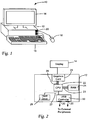
- an exemplary hardware environment in which aspects of the present invention may be implemented includes a computer system 10 with a system unit 12 and a display unit 14.
- the display unit 14 graphically displays output from the data processing operations performed by the system unit 12, and may be of a Liquid Crystal Display (LCD) type, a Cathode Ray Tube (CRT) type, or any other suitable type of display.
- LCD Liquid Crystal Display
- CRT Cathode Ray Tube
- Devices such as a keyboard 16 and a mouse 18 provide input to the data processing operations, and are connected to the system unit 10 via a USB port 20.
- Various other input and output devices may be connected to the system unit 12, and alternative interconnection modalities may be substituted with the USB port 20.
- the system unit 12 includes a Central Processing Unit (CPU) 22, which may represent one or more conventional types of such processors, such as an IBM PowerPC, Intel Pentium (x86) processors, and so forth.
- a Random Access Memory (RAM) 24 temporarily stores results of the data processing operations performed by the CPU 22, and is interconnected thereto typically via a dedicated memory channel 23.
- the system unit 10 may also include permanent storage devices such as a hard drive 26, which are also in communication with the CPU 22 over an i/o bus 27. Other types of storage devices such as tape drives, Compact Disc drives, and the like may also be connected.
- a graphics card 28 is also connected to the CPU 22 via a video bus 29, and transmits signals representative of display data to the display 14.
- a USB controller 30 translates data and instructions to and from the CPU 22 for external peripherals connected to the USB port 20. Additional devices such as printers, scanners microphones, speakers, and the like may be connected to the system unit 12.
- the system unit 12 may utilize any operating system having a graphical user interface (GUI), such as WINDOWS from Microsoft Corporation of Redmond, Washington, MACOS from Apple, Inc. of Cupertino, CA, various versions of UNIX with the X-Windows windowing system, and so forth.
- GUI graphical user interface
- the system unit 12 executes one or more computer programs, with the results thereof being displayed on the display unit 14.
- the operating system and the computer programs are tangibly embodied in a computer-readable medium, e.g. one or more of the fixed and/or removable data storage devices including the hard drive 26. Both the operating system and the computer programs may be loaded from the aforementioned data storage devices into the RAM 24 for execution by the CPU 22.
- the computer programs comprise instructions which, when read and executed by the CPU 22, cause the same to perform the steps necessary to execute the steps or features of the present invention.
- the foregoing computer system 10 represents only one exemplary apparatus suitable for implementing aspects of the present invention. As such, the computer system 10 may have many different configurations and architectures. Any such configuration or architecture may be readily substituted without departing from the scope of the present invention.
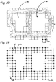
- an aspect of the present invention relates to a method for emphasizing differences in graphical appearances between an original document 32 and a modified document 34.
- both the original document 32 and the modified document 34 are stored as a Portable Document Format (PDF) file, which, as described above, include text, vector graphics, and raster (bitmap) graphics.
- PDF Portable Document Format
- a heading 36 of the original document 32 is "Planning Desk,” and includes an illustration of a house with a slanted left roofline 38.
- the heading 36 of the modified document 34 is "Planning".
- the roofline 38 has been changed altered. It is understood that the foregoing graphical elements of the original document 32 and the modified document 34 are presented for exemplary purposes only. According to an aspect of the present invention, each of the aforementioned differences is highlighted for rapidly identifying the same.
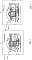
- the method includes a step 200 of receiving a first bitmap 48 of the modified document 34, and a second bitmap 50 of the original document 32.
- the original document 32 and the modified document 34 are PDF files, with the contents thereof being stored as discrete objects of text and geometric primitives. Accordingly, the original document 32 is converted to the second bitmap 50 and the modified document 34 is converted to the first bitmap 48 by a converter 52. It is contemplated that the original document 32 and the modified document 34 exist as bitmap files, in which case the aforementioned conversion is skipped.
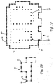
- an exemplary bitmap 54 is comprised of rows 56 and columns 58 of pixels 60.
- the pixels 60 are arranged to define the letter "T" in the exemplary bitmap 54.
- Each of the pixels 60 represents one point in the image, and is particularly referenced by a set of coordinates identifying a particular one of the rows 56 and a particular one of the columns 58. Further, each of the pixels 60 has associated therewith a set of three luminance values.
- a first luminance value represents the intensity of the red color
- a second luminance value represents the intensity of the green color
- a third luminance value represents the intensity of the blue color.
- the intensity is represented as a numerical value, typically between 0 and 255 for an 8-bit color depth. By combining varying intensities of the red, green, and blue colors, any color may be represented. Along these lines, the resolution of the bitmap may be varied according to the number of pixels per inch.
- the scale of the bitmap may be adjusted based upon a specified Dots Per Inch (DPI)/Points Per Inch (PPI) setting.
- the offset may be adjusted based on a specified offset value. Further preparations for comparing the bitmaps include overwriting the edges of the bitmap based upon a margin setting. A copy of the respective one of the bitmaps of the original document 32 and the modified document 34 may be stored as a temporary file on the hard drive 26 or the RAM 24. For faster access, the bitmaps are locked into the RAM 24.
- the method continues with deriving a set of difference points 62 based upon a comparison of the first bitmap 48 and the second bitmap 50 by a differencer 63.
- the difference points 62 are representative of pixels within the first and second bitmaps 48, 50 having pixel value differences exceeding a predetermined threshold. More particularly, the red, green, and blue luminance values are compared for each pixel in the first and second bitmaps 48, 50. If the maximum difference amongst the red, green, and blue components is greater than a predetermined color sensitivity setting, the coordinates for the particular pixel is retained as one of the difference points 62.
- the difference points 62 are also representative of coordinates within the first and second bitmaps 48, 50 with neighboring pixel value differences exceeding a predetermined threshold.
- each of the neighboring pixels is compared with the corresponding one of the pixels in the other bitmap.
- the coordinates of the initial pixel is retained as one of the difference points 62.
- the extent to which neighboring pixels are recursively examined in this manner is determined by a proximity setting. In this regard, documents with high noise/error content may be processed differently to avoid false positives as compared to documents with low noise/error content.
- FIG. 8 is a visual representation of the difference points 62 derived in accordance with step 202 and as described above.
- the method in accordance with an aspect of the present invention includes a step 204 of superposing a spatial index or grid 64 on to the set of difference points 62.
- a superposer 66 receives input in the form of difference points 62 and the grid 64, and generates a combined grid/difference point plot 67.
- a visual representation of the plot 67 is shown in FIG. 9 , though only one group of difference points 62 with the grid 64 overlaid thereon is illustrated.
- the grid 64 covers the entire field of the first or second bitmap 48, 50.
- the grid 64 is defined by contiguously spaced cells 68 bound by cell vertices 70 that are intersection points of gridlines 72.
- the size of the cells 68 in relation to the first and second bitmaps 48, 50 is user-defined, though a default value may be assigned. As will be explained further below, the size of the cells 68, or the distribution of the gridlines 72, affects the resolution and degree of accuracy in identifying differences.
- a step 206 of deriving polygon vertices from the cell vertices 70 follows.
- the cell vertices 70 of a plurality of adjacent cells 68 are utilized, with each having a predetermined density of a subset of the difference points 62 disposed within such cells 68.
- the density of difference points 62 in each of the cells 68 is determined by a density processor 69, and those cells 68 having a predetermined threshold density are retained.
- a histogram of the difference points 62 segregated into the cells 68 of the grid 64 is generated.
- the density of difference points 62 in each of the neighboring cells 68 are determined. If the neighboring cells 68 have a sufficient density, then the one of the cells having at least one difference point but insufficient density of difference points 62 is retained. In this regard, the cells 68 containing noise are removed, while the cells 68 containing the periphery of legitimate clusters of difference points 62 are retained.
- the size of the cells 68 should be maximized for decreasing the number to be processed, but not to the extent of affecting the accuracy in which the corresponding annotation covers the differences.
- the cell size may be modified before processing.
- a visual representation of the active grid list 74 is shown. Along these lines, there may be more than one group of cells 68 that have been retained, but with each group being located apart from another. As such, the step 206 is also understood to encompass the process of grouping adjacent cells 68 in the active grid list 74. Generally, a cell grouper 75 performs this process with an input of the active grid list 74, and outputs cell group lists 78. This process involves a function that recursively searches adjacent cells 68 to determine whether it has been retained.
- a first iteration 76 sequentially examines an east direction 76a, a northeast direction 76b, a north direction 76c, a northwest direction 76d, a west direction 76e, a southwest direction 76f, a south direction 76g, and a southeast direction 76h.
- a second iteration 77 is initiated with the examination of an east direction 77a, continuing on to a northeast direction 77b, a north direction 77c, and so forth.
- cell group lists 78 Whenever a particular cell has been determined to be associated with a group, it is recorded in one of the cell group lists 78.
- the cell group lists 78 have been mentioned in the plural, it is understood that the data contained therein be stored in a single list segregated into multiple groups.
- the step of generating polygon vertices continues with a polygon expander 80 calculating the coordinates of the cell vertices 70 corresponding to the four corners of each of the cells 68 in the cell group lists 78.
- a polygon expander 80 calculating the coordinates of the cell vertices 70 corresponding to the four corners of each of the cells 68 in the cell group lists 78.
- the particular cell vertices 70 that define a first exemplary polygon 82 are also referred to as polygon vertices 84.
- the method in accordance with an aspect of the present invention concludes with a step 208 of generating an annotation 91 from the polygon vertices 84 with an annotation generator 93.
- the step 208 typically involves additional processing of the polygon vertices 84, however.
- the first exemplary polygon 82 may be categorized as having a solid interior, that is, each of the cells 68 within the bounds of the cell vertices 70 has a sufficient density of the difference points 62.
- FIG. 10 and 11 the first exemplary polygon 82 may be categorized as having a solid interior, that is, each of the cells 68 within the bounds of the cell vertices 70 has a sufficient density of the difference points 62.
- a second exemplary polygon 86 may be categorized as having a hollow interior or cavity 88, in which the cells 68 originally superposed on those regions of the cavity 88 have not been retained according to the processes described above because of an insufficiency in density of the difference points 62 therein. This is most common where a border has been added between the compared documents, but where content within such border has not been modified.
- the polygon is classified as having a solid interior or a hollow interior.
- a flag may be set for later processing based upon a density determination made with respect to the polygon vertices.
- the number of possible cell vertices for a given rectangular region is compared against the number of actual cell vertices in that same rectangular region.
- the ratio is more than 60%, it is deemed to have a hollow interior, and the flag is set. Any other suitable ratio may be substituted without departing from the scope of the present invention.
- there are fifteen actual cell vertices 84 there are fifteen actual cell vertices 84, and would be a total of twenty if none had been removed. The ratio is 75%, so it is not flagged because it has a solid interior.
- interior polygon vertices are removed. More particularly, an interior polygon vertex is understood to refer to those polygon vertices that are internal to the polygon and do not define a border of the same. According to one embodiment, this determination is made by querying for the existence of neighboring polygon vertices in all directions. For example, as shown in FIG. 11 , a first interior polygon vertex 89 has eight neighboring polygon vertices 90a-90h. In other words, the first interior polygon vertex 89 is surrounded and enclosed by the neighboring polygon vertices 90a-90h. Similarly, as shown in FIG. 13 , second internal polygon vertices 90 of the second exemplary polygon 86, are removed.
- each of the second interior polygon vertices 90 have, as indicated above, neighboring polygon vertices in all directions.
- FIGS. 14 and 15 show the first and second exemplary polygons 82, 86, respectively, after removing the interior polygon vertices as set forth above.
- first and second polygons 82, 86 are stored as lists of coordinates corresponding to the polygon vertices 84 thereof, but in no particular order. In other words, the proper outline of boundaries has not yet been determined.
- the method continues with a step 224 of deriving boundaries from the polygon vertices 84 by storing in a trace list at least a subset the polygon vertices. This process is otherwise referred to as "tracing" a boundary.
- the outer boundary is derived for polygons with a solid interior as well as for polygons with a hollow interior.
- the process of deriving the outer boundary involves storing the polygon vertices 84 in an outer trace list. Where the polygon has a solid interior, all of the polygon vertices 84 are traced to derive the outer boundary.
- a first outer boundary 92 of the first exemplary polygon 82 is derived beginning with a starting vertex 93.
- Each of the polygon vertices 84 is traversed in a clockwise direction and the coordinates thereof are stored in the outer trace list until reaching the starting vertex 93.
- a first subset 85 of all of the polygon vertices 84 are traced to derive a second outer boundary 94 of the second exemplary polygon 86, with a second subset 87 of the polygon vertices 84 being traced to derive the inner boundaries.
- the process begins with a starting vertex 95.
- the first subset 85 of the polygon vertices 84 are traversed in a clockwise direction, and the coordinates thereof are stored in the outer trace list until reaching the starting vertex 95.
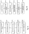
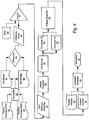
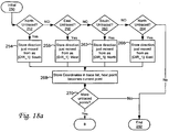
- the process of tracing the polygon vertices 84 begins with an initial state 250, and utilizes a first variable that stores the direction from which the current polygon vertex was traced and a second variable that stores the current polygon vertex from which further tracing is conducted.
- a first static decision branch 252 it is determined whether there is an untraced polygon vertex in the northward direction. If there is, the first variable is assigned a value of south, per storage step 254. Otherwise, it is next determined whether there is an untraced polygon vertex in the eastward direction per a second static decision branch 256.
- the first variable is assigned a value of west according to a second storage step 258. If not, the process continues with a third static decision branch 260. Here, it is determined whether there is an untraced polygon vertex in the southward direction. If there is, the first variable is assigned a value of north in storage step 262. If not, it is then determined whether there is an untraced polygon vertex in the westward direction according to a fourth static decision branch 264. The first variable is assigned a value of east per fourth storage step 266, if the fourth static decision branch 264 determined that the westward direction had an untraced polygon vertex. If not, the process ends 292. After executing one of the first, second, third, and fourth storage operations 254, 258, 262, and 266, the coordinates in the second variable are stored in the trace list according to step 268.
- the method continues into a dynamic part in which the order of directions to attempt to trace changes depending on direction from which the current polygon vertex was scanned. Otherwise, the process ends 292.
- the value stored in the first variable is used to correlate to a one of the starting rows 300a-d in the trace order list of FIG. 18b .
- the term specified row refers to the one of the starting rows 300a-d correlated to the direction value in the first variable.
- the direction in the first column DIR_1 of the specified row is examined to determine whether there is an untraced polygon vertex.
- the direction in the third column DIR_3 of the specified row is stored in the first variable according to a storage step 274. Otherwise, per a second dynamic decision branch 276, the direction in the second column DIR_2 of the specified row is examined for an untraced polygon vertex. If the decision yields a true result, then the first variable is re-written with the direction in the fourth column DIR_4 of the specified row per storage step 278. If the decision yields a false result, then the direction in the third column DIR_3 is checked for an untraced polygon vertex according to a third dynamic decision branch 280. If there is one, then per storage step 282, the first variable is re-written with the direction in the first column DIR_1 of the specified row.
- a fourth dynamic decision branch 284 the direction in the fourth column DIR_4 is examined for an untraced polygon. If there is, the first variable is re-written with the direction in the second column DIR_2. Otherwise, the process ends 292.
- the coordinates stored in the second variable are transferred to the trace list, and incremented to the coordinates of the discovered untraced polygon vertex.
- decision branch 290 it is determined whether the starting point is nearby. If not, the process returns to the decision branch 270. If there is, the process ends 292.
- first polygon vertex 96 also the starting point 95, and to the north thereof, a second polygon vertex 98.
- a third polygon vertex 100 To the west of the polygon vertex 98 is a third polygon vertex 100, and to the north of that is a fourth polygon vertex 102.
- the process determines whether there is an untraced vertex to the north per the first static decision branch 252. Since a positive determination is made, the first variable is stored with the direction south as per storage step 254. Thereafter, the coordinates of the first polygon vertex 96 are stored in the trace list per step 268, and the second variable is re-written with the coordinates of the discovered second polygon vertex 98.
- the process continues into the first dynamic decision branch 272.
- the one of the starting rows 300a-d are correlated to the direction value stored in the first variable, which is south.
- row 300a in which D1R_1 is south, DIR_2 is west, DIR_3 is north, and DIR_4 is east, is the specified row.
- the process continues through each of the first, second and third dynamic decision branches 272, 276, 280, and generates a true result at the fourth dynamic decision branch 284, as the third polygon vertex 100 is to the east.
- the first variable is rewritten with DIR_2, which is west.
- step 288 the coordinates of the second polygon vertex, as stored in the second variable, is written to the trace list. Further, the newly discovered fourth polygon vertex 102 is written to the second variable. Because the starting point is not nearby according to a response from the decision branch 290, the process returns to the decision branch 270.
- the process continues with the first dynamic decision branch 272.
- the first variable has a value of west, and so row 300b in which DIR_1 is west, DIR_2 is north, DIR_3 is east, and DIR 4 is south is the specified row.
- the process continues through the first dynamic decision branch 272 because there is no untraced polygon vertex to the west.
- the fourth polygon vertex 102 which is north of the third polygon vertex 100, is discovered.
- the first variable is rewritten with south, because the direction in column D1R_4 and row 300b is south.
- the coordinates of the third polygon vertex 100 is written, and the second variable is incremented to the coordinates of the fourth polygon vertex 102, according to step 288.
- the end 292 is reached.
- the above-described tracing of the outer boundary 94 proceeds in a generally clockwise direction. It will be understood by those of ordinary skill in the art that a counter-clockwise direction may be readily substituted by changing the order of the first, second, third, and fourth decision branches 232, 234, 236, and 238.
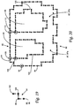
- the step 224 of tracing the boundary is also understood to encompass the processing of inner boundaries. Where the aforementioned flag is set, indicating that the polygon to which it pertains is hollow, the deriving of the inner boundaries begins. As indicated above, the inner boundaries are derived from a second subset of the polygon vertices 84. Where multiple sections of inner boundaries exist, multiple groups of the aforementioned second subset of the polygon vertices 84 are processed.
- deriving a first inner boundary 104 begins with identifying the polygon vertices 84 of both the first subset 85 (relating to the outer boundary 94) and the second subset 87 (relating to the first inner boundary 104) that define the shortest distance between the two. More particularly, each of the polygon vertices 84 in the first subset 85 are traversed, calculating the distance to the nearest untraced polygon vertex of the first group 87a of second subset 87.
- these points are identified as a first outer cavity junction point 106, and a first inner cavity junction point 108, which are stored for future reference.
- each of the polygon vertices 84 associated with the first group 87a of the second subset 87 is traced to derive the first inner boundary 104.
- This process is almost identical to that described above in relation to identifying the second outer boundary 94, except the coordinates of the traced polygon vertices 84 are stored in an inner trace list, and the trace proceeds in a counter-clockwise direction, as opposed to a clockwise direction as described above in relation to tracing an outer boundary, to ensure that the cavity 88 is not filled.
- the remaining polygon vertices 84 of the first subset (relating to the outer boundary 94) and the second subset 87 of the polygon vertices 84 that define the shortest distance between the two is identified.
- the remaining polygon vertices 84 in the first subset 85 are traversed as above, with the distance to the nearest untraced polygon vertex of the second group 87b of the second subset 87 being calculated.
- a second outer cavity junction point 110 and a second inner cavity junction point 112 are identified.
- each of the polygon vertices 84 in the second group 87b of the second subset 87 are traced in a counter-clockwise direction, the coordinates thereof being stored in the inner trace list.
- the coordinates of the second outer and inner cavity junction points 110, 112 are stored for later reference.
- an intermediate polygon vertex is any polygon vertex lying within a single contiguous line segment that defines a boundary of the polygon.
- a continuous line segment 114 defines the first outer boundary 92 of the first exemplary polygon 82, and includes segment polygon vertices 116a, 116b, 116c, and 116d.
- the beginning of the continuous line segment 114 is defined by the segment polygon vertex 116a, while the ending is defined by the segment polygon vertex 116d.
- the intermediate polygon vertices, the segment polygon vertices 116b and 116c do not contribute to the shape of the polygon 82, and slows down the processing of any annotations generated therefrom. Accordingly, the segment polygon vertices 116b and 116c are removed, as are the other polygon vertices 84 that have similar characteristics as described above. Referring to FIG. 20 , it will be appreciated that regardless of the first and second outer cavity junction points 106, 110 being intermediate polygon vertices, these are not removed as such points are needed for properly defining and connecting the second polygon 86 to the cavities 88. It will also be appreciated that if the first and second inner cavity junction points 108, 112 are intermediate polygon vertices, these will not be removed for the same reason.
- FIG. 22 shows the first exemplary polygon 82 including a first inner corner 120, a second inner corner 122, and a third inner corner 124.
- inner corners refer to those portions of the first polygon 82 that are concave with respect to the exterior thereof.
- the central vertices of polygon corners are determined by examining the direction of adjoining polygon vertices 84, and retrieving the remaining polygon vertices 84 to determine whether others exist on a straight line in the opposite direction from the adjoining polygon vertices 84.
- the first inner corner 120 is defined by a beginning vertex 126, an ending vertex 128, and central vertices 130a, 130b, and 130c.
- the outer boundary 92 extends directly from the beginning vertex 126 to the ending vertex 128.
- a central vertex 132 of the second inner corner is removed, as is a central vertex 134 of the third inner corner 134.
- FIG. 23 shows the first inner boundary 104 of the second exemplary polygon 86 defining the cavity 88.
- Both first and second central vertices 137, 139 are identified and removed in the same manner as described above. It will be appreciated that the coverage of the annotation is increased by removing the central vertices 137, 139.
- the process of generating the annotation concludes with a step 229 of assigning the values of the polygon vertices defining the outer boundaries and the inner boundaries, as applicable to the vertices that define the visual appearance of the annotation.
- the first outer and inner cavity junction points 106,108 and the second outer and inner cavity junction points 110, 112 serve to connect the inner boundaries 104, 105 to the outer boundary 94.
- annotations may have a variety of parameters that affect the visual appearance thereof upon rendering, which may applied to the annotation during generation.
- the annotation may be assigned a subject, a line and fill color, opacity, line stylization, locking parameters, and so forth.
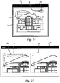
- FIGS. 24 and 25 there are provided various ways of presenting the annotations to the user for rapid identification of differences.
- the annotations 150 are overlaid in the modified document 34, which is displayed in a conventional graphical user interface 152.
- FIG. 25 the annotations 150 are overlaid on the modified document 34, with the modified document and the original document 32 being displayed simultaneously in the graphical user interface 152.
- the view of the modified document 34 and the original document 32 is synchronized, that is, when one of the modified or original documents 32, 34 is magnified or panned as shown in the example of FIG. 25 , the other document magnifies and pans to the same extent.
- Other user interface enhancements known in the art may be readily substituted without departing from the scope of the present invention.
Landscapes
- Engineering & Computer Science (AREA)
- Theoretical Computer Science (AREA)
- Physics & Mathematics (AREA)
- General Physics & Mathematics (AREA)
- Audiology, Speech & Language Pathology (AREA)
- Computational Linguistics (AREA)
- General Health & Medical Sciences (AREA)
- Health & Medical Sciences (AREA)
- General Engineering & Computer Science (AREA)
- Artificial Intelligence (AREA)
- Computer Vision & Pattern Recognition (AREA)
- Multimedia (AREA)
- Processing Or Creating Images (AREA)
- User Interface Of Digital Computer (AREA)
Claims (14)
- Verfahren zum Hervorheben von Differenzen in grafischen Erscheinungen zwischen einem originalen Dokument (32) und einer modifizierten Version des originalen Dokuments (34) mit angefügten Annotationen, wobei das Verfahren Folgendes beinhaltet:Empfangen einer ersten Bitmap (50) des modifizierten Dokuments und einer zweiten Bitmap (50) des originalen Dokuments (200);Ableiten eines Satzes Differenzpunkte (202) basierend auf einem Vergleich der ersten Bitmap und der zweiten Bitmap, wobei die Differenzpunkte für Koordinaten innerhalb der ersten und zweiten Bitmap repräsentativ sind, die Pixelwertdifferenzen aufweisen, die einen vorbestimmten Grenzwert überschreiten;Superpositionieren eines räumlichen Indexes auf dem Satz Differenzpunkte (204), wobei der räumliche Index durch zusammenhängend beabstandete Zellen, begrenzt von Zelleckpunkten, definiert ist, wobei jede Zelle eine Vielzahl von Differenzpunkten bedeckt;Generieren von Polygoneckpunkten (84) aus den Zelleckpunkten einer Vielzahl von angrenzenden Zellen, die jeweils eine vorbestimmte Dichte eines Teilsatzes der damit assoziierten Differenzpunkte aufweisen;Generieren aus den Polygoneckpunkten einer Annotation (91), die durch Annotationseckpunkte (208) definiert ist; und Präsentieren der Annotation an einen Benutzer.
- Verfahren gemäß Anspruch 1, wobei der Schritt des Generierens der Annotation ferner Folgendes einschließt:Ableiten einer äußeren Grenze (92) aus einem ersten Teilsatz der Polygoneckpunkte; undZuordnen der Polygoneckpunkte, die die äußere Grenze (92) definieren, auf die Annotationseckpunkte.
- Verfahren gemäß Anspruch 2, wobei nach dem Generieren der Polygoneckpunkte das Verfahren ferner Folgendes einschließt:Entfernen der inneren Polygoneckpunkte (90), wobei die inneren Polygoneckpunkte innerhalb der äußeren Grenze liegen und von benachbarten Polygoneckpunkten umgeben sind.
- Verfahren gemäß Anspruch 2, wobei das Ableiten der äußeren Grenze aus dem ersten Teilsatz der Polygoneckpunkte Folgendes einschließt:sequenzielles Speichern in einer äußeren Trace-Liste von jedem des ersten Teilsatzes der Polygoneckpunkte um die äußere Grenze von einem äußeren Startpunkt in eine erste im Allgemeinen Drehrichtung, wobei die Polygoneckpunkte in der äußeren Trace-Liste mit einem ersten Abschnitt der Annotationseckpunkte assoziiert sind.
- Verfahren nach Anspruch 2, das ferner Folgendes beinhaltet:Entfernen von jedem Polygoneckpunkt, der innerhalb eines einzelnen zusammenhängenden Liniensegments liegt, das die äußere Grenze definiert; undEntfernen der zentralen Eckpunkte von den Polygonecken.
- Verfahren gemäß Anspruch 2, wobei der Schritt des Generierens der Annotation (91) ferner Folgendes einschließt:Ableiten einer inneren Grenze (104) aus einer oder mehreren Gruppen eines zweiten Teilsatzes der Polygoneckpunkte; undZuordnen der Polygoneckpunkte, die die eine oder die mehreren inneren Grenzen (104) definieren, auf die Annotationseckpunkte.
- Verfahren gemäß Anspruch 6, wobei nach dem Generieren der Polygoneckpunkte das Verfahren ferner Folgendes einschließt:Entfernen der inneren Polygoneckpunkte (90), wobei die inneren Polygoneckpunkte innerhalb der äußeren Grenze (92) liegen und der inneren Grenze (104) und von benachbarten Polygoneckpunkten umgeben sind.
- Verfahren gemäß Anspruch 6, wobei das Ableiten der inneren Grenze (104) aus einer oder mehreren Gruppen des Teilsatzes der Polygoneckpunkte Folgendes einschließt:sequenzielles Speichern in einer inneren Trace-Liste einer ersten der Gruppen des zweiten Teilsatzes der Polygoneckpunkte um eine erste der inneren Grenzen von einem inneren Startpunkt in eine zweite im Allgemeinen Drehrichtung, wobei die Polygoneckpunkte in der inneren Trace-Liste mit einem zweiten Abschnitt der Annotationseckpunkte assoziiert sind.
- Verfahren gemäß Anspruch 6, wobei das Ableiten der inneren Grenze (104) aus einer der Gruppen des Teilsatzes der Polygoneckpunkte Folgendes einschließt:sequenzielles Speichern in der inneren Trace-Liste einer zweiten der Gruppen des zweiten Teilsatzes der Polygoneckpunkte um eine zweite der inneren Grenzen von einem zweiten inneren Startpunkt in die zweite im Allgemeinen Drehrichtung.
- Verfahren gemäß Anspruch 6, das weiter Folgendes beinhaltet:Entfernen von jedem Polygoneckpunkt, der innerhalb eines einzelnen zusammenhängenden Liniensegments liegt, das eines der äußeren Grenze (92) und der inneren Grenze (104) definiert; undEntfernen der zentralen Eckpunkte von den Polygonecken.
- Verfahren gemäß Anspruch 1, wobei sich die Pixelwertdifferenzen auf rote, grüne und blaue Luminanzwerte beziehen.
- Verfahren gemäß Anspruch 1, wobei die Differenzpunkte für Koordinaten innerhalb der ersten und zweiten Bitmap repräsentativ sind, die benachbarte Pixelwertdifferenzen aufweisen, die einen vorbestimmten Grenzwert überschreiten.
- Verfahren gemäß Anspruch 1, das ferner Folgendes beinhaltet:Umwandeln des modifizierten Dokuments in die erste Bitmap, die für das modifizierte Dokument repräsentativ ist, und des originalen Dokuments in die zweite Bitmap, die für das originale Dokument repräsentativ ist.
- Verfahren gemäß Anspruch 1, das ferner Folgendes beinhaltet:Überlagern der Annotation auf das modifizierte Dokument, wobei das modifizierte Dokument in einer grafischen Benutzerschnittstelle angezeigt wird.
Priority Applications (2)
| Application Number | Priority Date | Filing Date | Title |
|---|---|---|---|
| EP16160453.3A EP3065063B1 (de) | 2007-01-24 | 2008-01-17 | Verfahren zur hervorhebung von unterschieden der grafischen erscheinung zwischen einem originaldokument und einem modifizierten dokument mit anmerkungen |
| EP18207652.1A EP3462333B1 (de) | 2007-01-24 | 2008-01-17 | Verfahren zur hervorhebung von unterschieden der grafischen erscheinung zwischen einem originaldokument und einem modifizierten dokument mit anmerkungen |
Applications Claiming Priority (2)
| Application Number | Priority Date | Filing Date | Title |
|---|---|---|---|
| US11/626,631 US8244036B2 (en) | 2007-01-24 | 2007-01-24 | Method for emphasizing differences in graphical appearance between an original document and a modified document with annotations |
| PCT/US2008/000623 WO2008091526A1 (en) | 2007-01-24 | 2008-01-17 | Method for emphasizing differences in graphical appearance between an original document and a modified document with annotations |
Related Child Applications (2)
| Application Number | Title | Priority Date | Filing Date |
|---|---|---|---|
| EP18207652.1A Division EP3462333B1 (de) | 2007-01-24 | 2008-01-17 | Verfahren zur hervorhebung von unterschieden der grafischen erscheinung zwischen einem originaldokument und einem modifizierten dokument mit anmerkungen |
| EP16160453.3A Division EP3065063B1 (de) | 2007-01-24 | 2008-01-17 | Verfahren zur hervorhebung von unterschieden der grafischen erscheinung zwischen einem originaldokument und einem modifizierten dokument mit anmerkungen |
Publications (3)
| Publication Number | Publication Date |
|---|---|
| EP2106594A1 EP2106594A1 (de) | 2009-10-07 |
| EP2106594A4 EP2106594A4 (de) | 2012-07-18 |
| EP2106594B1 true EP2106594B1 (de) | 2016-04-13 |
Family
ID=39641275
Family Applications (3)
| Application Number | Title | Priority Date | Filing Date |
|---|---|---|---|
| EP08724584.1A Active EP2106594B1 (de) | 2007-01-24 | 2008-01-17 | Verfahren zur hervorhebung von unterschieden der grafischen erscheinung zwischen einem originaldokument und einem modifizierten dokument mit anmerkungen |
| EP18207652.1A Active EP3462333B1 (de) | 2007-01-24 | 2008-01-17 | Verfahren zur hervorhebung von unterschieden der grafischen erscheinung zwischen einem originaldokument und einem modifizierten dokument mit anmerkungen |
| EP16160453.3A Active EP3065063B1 (de) | 2007-01-24 | 2008-01-17 | Verfahren zur hervorhebung von unterschieden der grafischen erscheinung zwischen einem originaldokument und einem modifizierten dokument mit anmerkungen |
Family Applications After (2)
| Application Number | Title | Priority Date | Filing Date |
|---|---|---|---|
| EP18207652.1A Active EP3462333B1 (de) | 2007-01-24 | 2008-01-17 | Verfahren zur hervorhebung von unterschieden der grafischen erscheinung zwischen einem originaldokument und einem modifizierten dokument mit anmerkungen |
| EP16160453.3A Active EP3065063B1 (de) | 2007-01-24 | 2008-01-17 | Verfahren zur hervorhebung von unterschieden der grafischen erscheinung zwischen einem originaldokument und einem modifizierten dokument mit anmerkungen |
Country Status (8)
| Country | Link |
|---|---|
| US (2) | US8244036B2 (de) |
| EP (3) | EP2106594B1 (de) |
| AU (1) | AU2008209631B2 (de) |
| CA (2) | CA2676487C (de) |
| DK (1) | DK2106594T3 (de) |
| ES (1) | ES2580154T3 (de) |
| HU (1) | HUE030334T2 (de) |
| WO (1) | WO2008091526A1 (de) |
Families Citing this family (19)
| Publication number | Priority date | Publication date | Assignee | Title |
|---|---|---|---|---|
| US7844076B2 (en) * | 2003-06-26 | 2010-11-30 | Fotonation Vision Limited | Digital image processing using face detection and skin tone information |
| US7853887B2 (en) * | 2007-06-26 | 2010-12-14 | Adobe Systems Incorporated | Detection and preview of graphical elements within a graphic |
| US10657314B2 (en) | 2007-09-11 | 2020-05-19 | E-Plan, Inc. | System and method for dynamic linking between graphic documents and comment data bases |
| US7813301B2 (en) * | 2008-05-08 | 2010-10-12 | Verizon Patent And Licensing Inc. | Shrink wrap technique for enclosing multiple polygons |
| US20110154191A1 (en) * | 2009-12-22 | 2011-06-23 | Biby Kuriakose | Methods, apparatus and articles of manufacture to present changes in clinical records |
| US8554021B2 (en) | 2010-10-19 | 2013-10-08 | Palo Alto Research Center Incorporated | Finding similar content in a mixed collection of presentation and rich document content using two-dimensional visual fingerprints |
| US8750624B2 (en) * | 2010-10-19 | 2014-06-10 | Doron Kletter | Detection of duplicate document content using two-dimensional visual fingerprinting |
| US10140420B2 (en) | 2011-10-12 | 2018-11-27 | Merge Healthcare Incorporation | Systems and methods for independent assessment of image data |
| US9135602B2 (en) | 2012-07-25 | 2015-09-15 | E-Plan, Inc. | Management of building plan documents utilizing comments and a correction list |
| US9665550B2 (en) * | 2012-11-30 | 2017-05-30 | Michael E. Lee | Expert based integrated annotation software interface and database using e-book technology |
| US9148395B2 (en) | 2013-03-12 | 2015-09-29 | International Business Machines Corporation | Displaying message content differential in popup window |
| US8978003B1 (en) * | 2013-09-27 | 2015-03-10 | Taiwan Semiconductor Manufacturing Company, Ltd. | Method of making semiconductor device and a control system for performing the same |
| RU2571378C2 (ru) * | 2013-12-18 | 2015-12-20 | Общество с ограниченной ответственностью "Аби Девелопмент" | Устройство и способ поиска различий в документах |
| JP6287992B2 (ja) * | 2015-07-30 | 2018-03-07 | 京セラドキュメントソリューションズ株式会社 | 画像形成装置 |
| US9792024B2 (en) | 2015-08-17 | 2017-10-17 | E-Plan, Inc. | Systems and methods for management and processing of electronic documents using video annotations |
| US10897490B2 (en) | 2015-08-17 | 2021-01-19 | E-Plan, Inc. | Systems and methods for augmenting electronic content |
| US10388048B2 (en) * | 2016-08-26 | 2019-08-20 | Adobe Inc. | Simplified mechanism for displaying multiple documents on a mobile device |
| US10643374B2 (en) * | 2017-04-24 | 2020-05-05 | Intel Corporation | Positional only shading pipeline (POSH) geometry data processing with coarse Z buffer |
| JP2023140981A (ja) * | 2022-03-23 | 2023-10-05 | 富士フイルムビジネスイノベーション株式会社 | 情報処理システム、情報処理装置、およびプログラム |
Citations (1)
| Publication number | Priority date | Publication date | Assignee | Title |
|---|---|---|---|---|
| US20040223648A1 (en) * | 2003-05-05 | 2004-11-11 | Keith Hoene | Determining differences between documents |
Family Cites Families (32)
| Publication number | Priority date | Publication date | Assignee | Title |
|---|---|---|---|---|
| JP2823882B2 (ja) | 1989-04-03 | 1998-11-11 | 株式会社リコー | 線画像ベクトル化方法 |
| US5142619A (en) * | 1990-02-21 | 1992-08-25 | International Business Machines Corporation | Method and apparatus for visually comparing files in a data processing system |
| US5048099A (en) * | 1990-05-21 | 1991-09-10 | Eastman Kodak Company | Polygon-based method for automatic extraction of selected text in a digitized document |
| US5050222A (en) * | 1990-05-21 | 1991-09-17 | Eastman Kodak Company | Polygon-based technique for the automatic classification of text and graphics components from digitized paper-based forms |
| JP3042945B2 (ja) * | 1993-07-07 | 2000-05-22 | 富士通株式会社 | 画像抽出装置 |
| JP3345224B2 (ja) * | 1995-03-06 | 2002-11-18 | 富士通株式会社 | パターン抽出装置、パターン再認識用テーブル作成装置及びパターン認識装置 |
| US5835634A (en) * | 1996-05-31 | 1998-11-10 | Adobe Systems Incorporated | Bitmap comparison apparatus and method using an outline mask and differently weighted bits |
| US6041335A (en) * | 1997-02-10 | 2000-03-21 | Merritt; Charles R. | Method of annotating a primary image with an image and for transmitting the annotated primary image |
| US6636631B2 (en) * | 1998-06-04 | 2003-10-21 | Matsushita Electric Industrial Co., Ltd. | Optical character reading method and system for a document with ruled lines and its application |
| US7036094B1 (en) * | 1998-08-10 | 2006-04-25 | Cybernet Systems Corporation | Behavior recognition system |
| US6324555B1 (en) * | 1998-08-31 | 2001-11-27 | Adobe Systems Incorporated | Comparing contents of electronic documents |
| US6591010B1 (en) * | 1999-07-29 | 2003-07-08 | International Business Machines Corporation | System and method for image detection and qualification |
| EP1119186A3 (de) * | 2000-01-19 | 2002-07-31 | Xerox Corporation | Verfahren zum Erzeugen von aliasfreien Text und Liniengraphiken in komprimierten Dokumenten |
| GB0009668D0 (en) * | 2000-04-19 | 2000-09-06 | Univ Manchester | Non-Parametric image subtraction using grey level scattergrams |
| US6573893B1 (en) * | 2000-11-01 | 2003-06-03 | Hewlett-Packard Development Company, L.P. | Voxel transfer circuit for accelerated volume rendering of a graphics image |
| US20040034832A1 (en) * | 2001-10-19 | 2004-02-19 | Xerox Corporation | Method and apparatus for foward annotating documents |
| US7239399B2 (en) * | 2001-11-13 | 2007-07-03 | Cyberoptics Corporation | Pick and place machine with component placement inspection |
| US20040205482A1 (en) * | 2002-01-24 | 2004-10-14 | International Business Machines Corporation | Method and apparatus for active annotation of multimedia content |
| US7092571B2 (en) * | 2002-03-29 | 2006-08-15 | Sun Microsystems, Inc. | Method and apparatus for regional image quantification verification |
| US7234106B2 (en) * | 2002-09-10 | 2007-06-19 | Simske Steven J | System for and method of generating image annotation information |
| JP4181892B2 (ja) * | 2003-02-21 | 2008-11-19 | キヤノン株式会社 | 画像処理方法 |
| US6937765B2 (en) | 2003-03-14 | 2005-08-30 | The Regents Of The University Of California | Method for contour extraction for object representation |
| JP4184842B2 (ja) * | 2003-03-19 | 2008-11-19 | 富士フイルム株式会社 | 画像判別装置、方法およびプログラム |
| US7983446B2 (en) * | 2003-07-18 | 2011-07-19 | Lockheed Martin Corporation | Method and apparatus for automatic object identification |
| US7536636B2 (en) * | 2004-04-26 | 2009-05-19 | Kodak Graphic Communications Canada Company | Systems and methods for comparing documents containing graphic elements |
| JP4562126B2 (ja) * | 2004-09-29 | 2010-10-13 | 大日本スクリーン製造株式会社 | 欠陥検出装置および欠陥検出方法 |
| JP4546291B2 (ja) * | 2005-03-01 | 2010-09-15 | キヤノン株式会社 | 画像処理装置およびその制御方法 |
| JP2006277167A (ja) * | 2005-03-29 | 2006-10-12 | Fuji Xerox Co Ltd | アノテーションデータ処理プログラム、装置、方法 |
| US7526129B2 (en) * | 2005-06-23 | 2009-04-28 | Microsoft Corporation | Lifting ink annotations from paper |
| US7590268B1 (en) * | 2005-10-17 | 2009-09-15 | Adobe Systems Incorporated | Method and apparatus for representing an area of a raster image by a centerline |
| WO2007067721A2 (en) * | 2005-12-08 | 2007-06-14 | Lenel Systems International, Inc. | System and method for counting people near objects |
| US8831357B2 (en) * | 2007-11-09 | 2014-09-09 | Cognitech, Inc. | System and method for image and video search, indexing and object classification |
-
2007
- 2007-01-24 US US11/626,631 patent/US8244036B2/en active Active
-
2008
- 2008-01-17 DK DK08724584.1T patent/DK2106594T3/en active
- 2008-01-17 EP EP08724584.1A patent/EP2106594B1/de active Active
- 2008-01-17 WO PCT/US2008/000623 patent/WO2008091526A1/en not_active Ceased
- 2008-01-17 EP EP18207652.1A patent/EP3462333B1/de active Active
- 2008-01-17 CA CA2676487A patent/CA2676487C/en active Active
- 2008-01-17 ES ES08724584.1T patent/ES2580154T3/es active Active
- 2008-01-17 CA CA2903818A patent/CA2903818C/en active Active
- 2008-01-17 EP EP16160453.3A patent/EP3065063B1/de active Active
- 2008-01-17 HU HUE08724584A patent/HUE030334T2/en unknown
- 2008-01-17 AU AU2008209631A patent/AU2008209631B2/en active Active
-
2012
- 2012-06-28 US US13/536,858 patent/US8509535B2/en active Active
Patent Citations (1)
| Publication number | Priority date | Publication date | Assignee | Title |
|---|---|---|---|---|
| US20040223648A1 (en) * | 2003-05-05 | 2004-11-11 | Keith Hoene | Determining differences between documents |
Also Published As
| Publication number | Publication date |
|---|---|
| CA2903818A1 (en) | 2008-07-31 |
| EP2106594A4 (de) | 2012-07-18 |
| EP3462333B1 (de) | 2024-07-03 |
| US8509535B2 (en) | 2013-08-13 |
| US20080175484A1 (en) | 2008-07-24 |
| ES2580154T3 (es) | 2016-08-19 |
| CA2676487A1 (en) | 2008-07-31 |
| HUE030334T2 (en) | 2017-05-29 |
| CA2903818C (en) | 2018-02-20 |
| DK2106594T3 (en) | 2016-07-25 |
| EP3065063A1 (de) | 2016-09-07 |
| EP2106594A1 (de) | 2009-10-07 |
| US8244036B2 (en) | 2012-08-14 |
| AU2008209631B2 (en) | 2012-03-01 |
| CA2676487C (en) | 2015-12-01 |
| EP3462333A1 (de) | 2019-04-03 |
| US20120299944A1 (en) | 2012-11-29 |
| EP3065063B1 (de) | 2019-01-02 |
| WO2008091526A1 (en) | 2008-07-31 |
| AU2008209631A1 (en) | 2008-07-31 |
Similar Documents
| Publication | Publication Date | Title |
|---|---|---|
| EP2106594B1 (de) | Verfahren zur hervorhebung von unterschieden der grafischen erscheinung zwischen einem originaldokument und einem modifizierten dokument mit anmerkungen | |
| JP5465015B2 (ja) | 文書を電子化する装置及び方法 | |
| JP3950498B2 (ja) | イメージ処理方法及び装置 | |
| Arteaga | Historical map polygon and feature extractor | |
| CA2676283C (en) | A method for aligning a modified document and an original document for comparison and difference highlighting | |
| JP2007279828A (ja) | 帳票処理装置、帳票様式作成装置、帳票、帳票処理用のプログラム、帳票様式作成用のプログラム | |
| JP6151802B2 (ja) | 文書の可視オブジェクト検索のためのプレフィルタリング | |
| Godfrey et al. | An adaptable approach for generating vector features from scanned historical thematic maps using image enhancement and remote sensing techniques in a geographic information system | |
| US9881210B2 (en) | Generating a computer executable chart visualization by annotating a static image | |
| JPH0612540B2 (ja) | 文書作成支援装置 | |
| US8990681B2 (en) | Method for aligning a modified document and an original document for comparison and difference highlighting | |
| Wang et al. | Vectorized Colorization of Icon Line Art Based on Closed Contour Extraction | |
| CN115661300A (zh) | 基于深度学习的网络安全可视化仪表盘生成方法 |
Legal Events
| Date | Code | Title | Description |
|---|---|---|---|
| PUAI | Public reference made under article 153(3) epc to a published international application that has entered the european phase |
Free format text: ORIGINAL CODE: 0009012 |
|
| 17P | Request for examination filed |
Effective date: 20090723 |
|
| AK | Designated contracting states |
Kind code of ref document: A1 Designated state(s): AT BE BG CH CY CZ DE DK EE ES FI FR GB GR HR HU IE IS IT LI LT LU LV MC MT NL NO PL PT RO SE SI SK TR |
|
| DAX | Request for extension of the european patent (deleted) | ||
| REG | Reference to a national code |
Ref country code: DE Ref legal event code: R079 Ref document number: 602008043495 Country of ref document: DE Free format text: PREVIOUS MAIN CLASS: G06F0017000000 Ipc: G06F0017220000 |
|
| A4 | Supplementary search report drawn up and despatched |
Effective date: 20120619 |
|
| RIC1 | Information provided on ipc code assigned before grant |
Ipc: G06T 7/00 20060101ALI20120613BHEP Ipc: G06F 17/22 20060101AFI20120613BHEP Ipc: G06T 11/60 20060101ALI20120613BHEP |
|
| 17Q | First examination report despatched |
Effective date: 20130524 |
|
| GRAP | Despatch of communication of intention to grant a patent |
Free format text: ORIGINAL CODE: EPIDOSNIGR1 |
|
| INTG | Intention to grant announced |
Effective date: 20151110 |
|
| GRAS | Grant fee paid |
Free format text: ORIGINAL CODE: EPIDOSNIGR3 |
|
| GRAA | (expected) grant |
Free format text: ORIGINAL CODE: 0009210 |
|
| AK | Designated contracting states |
Kind code of ref document: B1 Designated state(s): AT BE BG CH CY CZ DE DK EE ES FI FR GB GR HR HU IE IS IT LI LT LU LV MC MT NL NO PL PT RO SE SI SK TR |
|
| REG | Reference to a national code |
Ref country code: GB Ref legal event code: FG4D |
|
| REG | Reference to a national code |
Ref country code: AT Ref legal event code: REF Ref document number: 790827 Country of ref document: AT Kind code of ref document: T Effective date: 20160415 Ref country code: CH Ref legal event code: EP |
|
| REG | Reference to a national code |
Ref country code: IE Ref legal event code: FG4D |
|
| REG | Reference to a national code |
Ref country code: DE Ref legal event code: R096 Ref document number: 602008043495 Country of ref document: DE |
|
| REG | Reference to a national code |
Ref country code: DK Ref legal event code: T3 Effective date: 20160714 |
|
| REG | Reference to a national code |
Ref country code: NL Ref legal event code: FP |
|
| REG | Reference to a national code |
Ref country code: SE Ref legal event code: TRGR |
|
| REG | Reference to a national code |
Ref country code: LT Ref legal event code: MG4D |
|
| REG | Reference to a national code |
Ref country code: ES Ref legal event code: FG2A Ref document number: 2580154 Country of ref document: ES Kind code of ref document: T3 Effective date: 20160819 |
|
| REG | Reference to a national code |
Ref country code: NO Ref legal event code: T2 Effective date: 20160413 |
|
| REG | Reference to a national code |
Ref country code: CH Ref legal event code: NV Representative=s name: MICHELI AND CIE SA, CH |
|
| REG | Reference to a national code |
Ref country code: NO Ref legal event code: CREP Representative=s name: BRYN AARFLOT AS, POSTBOKS 449 SENTRUM, 0104 OSLO |
|
| PG25 | Lapsed in a contracting state [announced via postgrant information from national office to epo] |
Ref country code: PL Free format text: LAPSE BECAUSE OF FAILURE TO SUBMIT A TRANSLATION OF THE DESCRIPTION OR TO PAY THE FEE WITHIN THE PRESCRIBED TIME-LIMIT Effective date: 20160413 Ref country code: LT Free format text: LAPSE BECAUSE OF FAILURE TO SUBMIT A TRANSLATION OF THE DESCRIPTION OR TO PAY THE FEE WITHIN THE PRESCRIBED TIME-LIMIT Effective date: 20160413 |
|
| PG25 | Lapsed in a contracting state [announced via postgrant information from national office to epo] |
Ref country code: PT Free format text: LAPSE BECAUSE OF FAILURE TO SUBMIT A TRANSLATION OF THE DESCRIPTION OR TO PAY THE FEE WITHIN THE PRESCRIBED TIME-LIMIT Effective date: 20160816 Ref country code: HR Free format text: LAPSE BECAUSE OF FAILURE TO SUBMIT A TRANSLATION OF THE DESCRIPTION OR TO PAY THE FEE WITHIN THE PRESCRIBED TIME-LIMIT Effective date: 20160413 Ref country code: GR Free format text: LAPSE BECAUSE OF FAILURE TO SUBMIT A TRANSLATION OF THE DESCRIPTION OR TO PAY THE FEE WITHIN THE PRESCRIBED TIME-LIMIT Effective date: 20160714 Ref country code: LV Free format text: LAPSE BECAUSE OF FAILURE TO SUBMIT A TRANSLATION OF THE DESCRIPTION OR TO PAY THE FEE WITHIN THE PRESCRIBED TIME-LIMIT Effective date: 20160413 |
|
| REG | Reference to a national code |
Ref country code: DE Ref legal event code: R097 Ref document number: 602008043495 Country of ref document: DE |
|
| REG | Reference to a national code |
Ref country code: FR Ref legal event code: PLFP Year of fee payment: 10 |
|
| PG25 | Lapsed in a contracting state [announced via postgrant information from national office to epo] |
Ref country code: SK Free format text: LAPSE BECAUSE OF FAILURE TO SUBMIT A TRANSLATION OF THE DESCRIPTION OR TO PAY THE FEE WITHIN THE PRESCRIBED TIME-LIMIT Effective date: 20160413 Ref country code: EE Free format text: LAPSE BECAUSE OF FAILURE TO SUBMIT A TRANSLATION OF THE DESCRIPTION OR TO PAY THE FEE WITHIN THE PRESCRIBED TIME-LIMIT Effective date: 20160413 Ref country code: RO Free format text: LAPSE BECAUSE OF FAILURE TO SUBMIT A TRANSLATION OF THE DESCRIPTION OR TO PAY THE FEE WITHIN THE PRESCRIBED TIME-LIMIT Effective date: 20160413 Ref country code: CZ Free format text: LAPSE BECAUSE OF FAILURE TO SUBMIT A TRANSLATION OF THE DESCRIPTION OR TO PAY THE FEE WITHIN THE PRESCRIBED TIME-LIMIT Effective date: 20160413 |
|
| PLBE | No opposition filed within time limit |
Free format text: ORIGINAL CODE: 0009261 |
|
| STAA | Information on the status of an ep patent application or granted ep patent |
Free format text: STATUS: NO OPPOSITION FILED WITHIN TIME LIMIT |
|
| 26N | No opposition filed |
Effective date: 20170116 |
|
| REG | Reference to a national code |
Ref country code: HU Ref legal event code: AG4A Ref document number: E030334 Country of ref document: HU |
|
| PG25 | Lapsed in a contracting state [announced via postgrant information from national office to epo] |
Ref country code: SI Free format text: LAPSE BECAUSE OF FAILURE TO SUBMIT A TRANSLATION OF THE DESCRIPTION OR TO PAY THE FEE WITHIN THE PRESCRIBED TIME-LIMIT Effective date: 20160413 |
|
| PG25 | Lapsed in a contracting state [announced via postgrant information from national office to epo] |
Ref country code: MC Free format text: LAPSE BECAUSE OF FAILURE TO SUBMIT A TRANSLATION OF THE DESCRIPTION OR TO PAY THE FEE WITHIN THE PRESCRIBED TIME-LIMIT Effective date: 20160413 |
|
| PG25 | Lapsed in a contracting state [announced via postgrant information from national office to epo] |
Ref country code: LU Free format text: LAPSE BECAUSE OF NON-PAYMENT OF DUE FEES Effective date: 20170117 |
|
| REG | Reference to a national code |
Ref country code: FR Ref legal event code: PLFP Year of fee payment: 11 |
|
| PGFP | Annual fee paid to national office [announced via postgrant information from national office to epo] |
Ref country code: NO Payment date: 20180122 Year of fee payment: 11 |
|
| PGFP | Annual fee paid to national office [announced via postgrant information from national office to epo] |
Ref country code: HU Payment date: 20180119 Year of fee payment: 11 |
|
| PG25 | Lapsed in a contracting state [announced via postgrant information from national office to epo] |
Ref country code: MT Free format text: LAPSE BECAUSE OF NON-PAYMENT OF DUE FEES Effective date: 20170117 |
|
| REG | Reference to a national code |
Ref country code: NO Ref legal event code: MMEP |
|
| PG25 | Lapsed in a contracting state [announced via postgrant information from national office to epo] |
Ref country code: BG Free format text: LAPSE BECAUSE OF FAILURE TO SUBMIT A TRANSLATION OF THE DESCRIPTION OR TO PAY THE FEE WITHIN THE PRESCRIBED TIME-LIMIT Effective date: 20160413 |
|
| PG25 | Lapsed in a contracting state [announced via postgrant information from national office to epo] |
Ref country code: NO Free format text: LAPSE BECAUSE OF NON-PAYMENT OF DUE FEES Effective date: 20190131 Ref country code: CY Free format text: LAPSE BECAUSE OF NON-PAYMENT OF DUE FEES Effective date: 20160413 |
|
| REG | Reference to a national code |
Ref country code: DE Ref legal event code: R079 Ref document number: 602008043495 Country of ref document: DE Free format text: PREVIOUS MAIN CLASS: G06F0017220000 Ipc: G06F0040120000 |
|
| PG25 | Lapsed in a contracting state [announced via postgrant information from national office to epo] |
Ref country code: HU Free format text: LAPSE BECAUSE OF NON-PAYMENT OF DUE FEES Effective date: 20190118 |
|
| REG | Reference to a national code |
Ref country code: DE Ref legal event code: R082 Ref document number: 602008043495 Country of ref document: DE Representative=s name: HERNANDEZ, YORCK, DIPL.-ING., DE Ref country code: DE Ref legal event code: R081 Ref document number: 602008043495 Country of ref document: DE Owner name: BLUEBEAM, INC., PASADENA, US Free format text: FORMER OWNER: BLUEBEAM SOFTWARE, INC., PASADENA, CALIF., US |
|
| REG | Reference to a national code |
Ref country code: CH Ref legal event code: PFA Owner name: BLUEBEAM, INC., US Free format text: FORMER OWNER: BLUEBEAM SOFTWARE, INC., US |
|
| REG | Reference to a national code |
Ref country code: NL Ref legal event code: HC Owner name: BLUEBEAM, INC.; US Free format text: DETAILS ASSIGNMENT: CHANGE OF OWNER(S), CHANGE OF OWNER(S) NAME; FORMER OWNER NAME: BLUEBEAM SOFTWARE, INC. Effective date: 20200115 |
|
| REG | Reference to a national code |
Ref country code: ES Ref legal event code: PC2A Owner name: BLUEBEAM, INC. Effective date: 20200207 |
|
| REG | Reference to a national code |
Ref country code: BE Ref legal event code: PD Owner name: BLUEBEAM, INC.; US Free format text: DETAILS ASSIGNMENT: CHANGE OF OWNER(S), CESSION; FORMER OWNER NAME: BLUEBEAM SOFTWARE, INC. Effective date: 20200107 |
|
| PG25 | Lapsed in a contracting state [announced via postgrant information from national office to epo] |
Ref country code: TR Free format text: LAPSE BECAUSE OF FAILURE TO SUBMIT A TRANSLATION OF THE DESCRIPTION OR TO PAY THE FEE WITHIN THE PRESCRIBED TIME-LIMIT Effective date: 20160413 |
|
| REG | Reference to a national code |
Ref country code: AT Ref legal event code: UEP Ref document number: 790827 Country of ref document: AT Kind code of ref document: T Effective date: 20160413 Ref country code: FI Ref legal event code: PCE Owner name: BLUEBEAM, INC. |
|
| PG25 | Lapsed in a contracting state [announced via postgrant information from national office to epo] |
Ref country code: IS Free format text: LAPSE BECAUSE OF FAILURE TO SUBMIT A TRANSLATION OF THE DESCRIPTION OR TO PAY THE FEE WITHIN THE PRESCRIBED TIME-LIMIT Effective date: 20160813 |
|
| REG | Reference to a national code |
Ref country code: AT Ref legal event code: HC Ref document number: 790827 Country of ref document: AT Kind code of ref document: T Owner name: BLUEBEAM, INC., US Effective date: 20200618 |
|
| P01 | Opt-out of the competence of the unified patent court (upc) registered |
Effective date: 20230514 |
|
| PGFP | Annual fee paid to national office [announced via postgrant information from national office to epo] |
Ref country code: NL Payment date: 20250121 Year of fee payment: 18 |
|
| PGFP | Annual fee paid to national office [announced via postgrant information from national office to epo] |
Ref country code: DE Payment date: 20250121 Year of fee payment: 18 |
|
| PGFP | Annual fee paid to national office [announced via postgrant information from national office to epo] |
Ref country code: DK Payment date: 20250124 Year of fee payment: 18 Ref country code: FI Payment date: 20250124 Year of fee payment: 18 |
|
| PGFP | Annual fee paid to national office [announced via postgrant information from national office to epo] |
Ref country code: ES Payment date: 20250225 Year of fee payment: 18 |
|
| PGFP | Annual fee paid to national office [announced via postgrant information from national office to epo] |
Ref country code: IE Payment date: 20250130 Year of fee payment: 18 Ref country code: SE Payment date: 20250121 Year of fee payment: 18 |
|
| PGFP | Annual fee paid to national office [announced via postgrant information from national office to epo] |
Ref country code: CH Payment date: 20250201 Year of fee payment: 18 Ref country code: AT Payment date: 20250122 Year of fee payment: 18 Ref country code: BE Payment date: 20250121 Year of fee payment: 18 |
|
| PGFP | Annual fee paid to national office [announced via postgrant information from national office to epo] |
Ref country code: FR Payment date: 20250127 Year of fee payment: 18 |
|
| PGFP | Annual fee paid to national office [announced via postgrant information from national office to epo] |
Ref country code: IT Payment date: 20250129 Year of fee payment: 18 Ref country code: GB Payment date: 20250128 Year of fee payment: 18 |