EP2106346B1 - Multi-color printing machine having a foil transfer device - Google Patents
Multi-color printing machine having a foil transfer device Download PDFInfo
- Publication number
- EP2106346B1 EP2106346B1 EP07856349A EP07856349A EP2106346B1 EP 2106346 B1 EP2106346 B1 EP 2106346B1 EP 07856349 A EP07856349 A EP 07856349A EP 07856349 A EP07856349 A EP 07856349A EP 2106346 B1 EP2106346 B1 EP 2106346B1
- Authority
- EP
- European Patent Office
- Prior art keywords
- coating
- foil
- printing
- sheet
- printed
- Prior art date
- Legal status (The legal status is an assumption and is not a legal conclusion. Google has not performed a legal analysis and makes no representation as to the accuracy of the status listed.)
- Not-in-force
Links
Images

Classifications
-
- B—PERFORMING OPERATIONS; TRANSPORTING
- B41—PRINTING; LINING MACHINES; TYPEWRITERS; STAMPS
- B41F—PRINTING MACHINES OR PRESSES
- B41F19/00—Apparatus or machines for carrying out printing operations combined with other operations
- B41F19/02—Apparatus or machines for carrying out printing operations combined with other operations with embossing
- B41F19/06—Printing and embossing between a negative and a positive forme after inking and wiping the negative forme; Printing from an ink band treated with colour or "gold"
-
- B—PERFORMING OPERATIONS; TRANSPORTING
- B41—PRINTING; LINING MACHINES; TYPEWRITERS; STAMPS
- B41P—INDEXING SCHEME RELATING TO PRINTING, LINING MACHINES, TYPEWRITERS, AND TO STAMPS
- B41P2219/00—Printing presses using a heated printing foil
- B41P2219/50—Printing presses using a heated printing foil combined with existing presses
- B41P2219/51—Converting existing presses to foil printing presses
Abstract
Description
Die Erfindung betrifft ein Verfahren und eine Vorrichtung zum Transfer bildgebender oder abdeckender Schichten von einer Trägerfolie auf Druckbogen nach dem Oberbegriff des Patentanspruchs 1.The invention relates to a method and a device for transferring imaging or covering layers from a carrier film to printing sheet according to the preamble of
Es ist bekannt metallische Schichten auf Druckbogen mittels eines Folientransferverfahrens herzustellen. So ist in der
Nachdem ein Druckbogen mit einem flächigen Klebstoffauftrag oder einem Klebstoffmuster versehen ist, wird er durch das Beschichtungswerk geführt, wobei mittels der Presswalze der auf dem Gegendruckzylinder aufliegende Druckbogen mit dem Folienmaterial in Verbindung gebracht wird. Dabei geht die nach unten liegende Funktionsschicht eine enge Verbindung mit den mit Klebstoff versehenen Bereichen auf dem Druckbogen ein. Danach haftet die Funktionsschicht lediglich im Bereich der mit Klebstoff versehenen Muster oder auch vollflächigen Kleberbereiche an, wobei der Trägerfolie die Funktionsschicht im Bereich der Klebstoffmuster entnommen wird. Der Druckbogen wird im beschichteten Zustand ausgelegt.After a printing sheet is provided with a two-dimensional adhesive application or an adhesive pattern, it is passed through the coating unit, wherein by means of the pressure roller, the pressure sheet resting on the impression cylinder is brought into contact with the film material. The down-facing functional layer engages tightly with the adhesive-provided areas on the signature. Thereafter, the functional layer adheres only in the area provided with adhesive pattern or even full-surface adhesive areas on, wherein the carrier film, the functional layer is removed in the region of the adhesive pattern. The print sheet is laid out in the coated state.
Nachteilig an den geschilderten Verfahrensweisen ist, dass sie nicht flexibel einsetzbar sind, ein umfangreiches Know How zu den komplexen Prozessen erfordern und schwierig zu handhaben sind.A disadvantage of the described procedures is that they are not flexible to use, require extensive know-how on the complex processes and are difficult to handle.
Aus der
Weiterhin sind aus der
Aufgabe der Erfindung ist es daher ein Verfahren nach dem Oberbegriff des Anspruchs 1 vorzusehen, mittels derer eine flexible Beschichtung von Druckbogen einfach, sicher, wirtschaftlich und exakt erfolgen kann, wobei Verfahren und Vorrichtung einfach handhabbar sein sollen.The object of the invention is therefore to provide a method according to the preamble of
Die Lösung dieser Aufgabe ergibt sich in einem Verfahren gemäß den Merkmalen der Patentanspruches 1.The solution of this problem results in a method according to the features of
In vorteilhafter Weise wird ein Verfahren vorgeschlagen, bei dessen Anwendung zum Beschichten oder auch Mehrfachbeschichten von ein- oder beidseitig zu bedruckenden Druckbogen eine Bogenrotationsdruckmaschine verwendet und die Beschichtung im Kaltfolienprägeverfahren durchgeführt wird.Advantageously, a method is proposed in the application for coating or multiple coating of one or both sides to be printed sheet used a sheet-fed rotary printing press and the coating is carried out in the cold foil stamping process.
Dabei kann in vorteilhafter Weise durch die Kombination von Beschichtungseinheiten wie z. B. Lackmodulen, einer Einrichtung zur Bogenwendung sowie Beschichtungsmodulen für eine ein- oder beidseitige Folienapplikation ermöglicht werden.It can be advantageously by the combination of coating units such. As paint modules, a device for perfecting and coating modules for a one- or two-sided film application are possible.
- 1. Eine ein- oder beidseitige Beschichtung eines Bedruckstoffes durch eine Folienapplikation mittels eines Kaltfolientransferverfahrens dient zur Herstellung von beliebigen Druckprodukten.1. A one- or two-sided coating of a printing substrate by a film application by means of a cold foil transfer process is used for the production of any printed products.
- 2. Im Inlinedrucken bzw. -beschichten kann mittels einer Bogenrotationsdruckmaschine und einer Kaltfolienpräge-Applikation zur Herstellung von Verbundverpackungen mit einem oder mehreren Beschichtungsmodulen innerhalb einer Druckmaschine die Verarbeitung von Folie, Papier mit Alu-bedampfter Kaschierung oder Alu-bedampften Papieren oder die Applikation einer weiteren Folienschicht vorgenommen werden.2. In inline printing or coating, by means of a sheet-fed rotary printing press and a cold foil embossing application for the production of composite packaging with one or more coating modules within a printing press, the processing of foil, paper with aluminum-evaporated lamination or aluminum-coated papers or the application of another Foil layer are made.
- 3. In Kombination von Verfahrensschritten zum Inlinedrucken, Inlinelackieren und Inlinebeschichten ist innerhalb einer einzigen Bogenrotationsdruckmaschine mit Lackmodulen und einer oder mehreren Kaltfolienprägeeinrichtungen die Herstellung von Druckprodukten unter Verarbeitung von Folie oder Papier verschiedener Qualitäten, die Applikation einer weiteren Folienschicht auch nach einer Vorbeschichtung möglich. Auch damit können Produkteigenschaften, optisch oder taktil wirksamen Vorbeschichtung und Applikation einer Schmuckfolie miteinander kombiniert werden.3. In combination of process steps for inline printing, inline coating and inline coating is within a single sheet-fed rotary printing press with coating modules and one or more cold foil stamping devices, the production of printed products by processing film or paper of different qualities, the application of a further film layer even after a pre-coating possible. Also with this product properties, optically or tactile effective pre-coating and application of a decorative film can be combined.
- 4. In der Kaltfolienprägeapplikation kann ggf. durch die Kombination von Drucken, Bogenwendung, Folienapplikation gegenüberliegende Seite ggf. Drucken und Lackieren eine Integration des Kaltfolienprägeverfahrens für allgemeine Anwendung für beidseitigen Druck- bzw. Beschichtung geeignet sein.4. In the cold foil embossing application, an integration of the cold foil embossing process for general application for double-sided printing or coating may possibly be suitable due to the combination of printing, sheet application, film application opposite side, if necessary printing and painting.
- 5. Die Verarbeitung von Alu-kaschierten Bedruckstoffen ist eine weitere Lösungsmöglichkeit, wobei eine Kaltfolienprägeapplikation in einer Bogenrotations- oder Flexodruckmaschine ermöglicht werden kann.5. The processing of aluminum-laminated substrates is another possible solution, with a cold foil embossing application can be made possible in a sheet-fed or flexographic printing machine.
- 6. Die Vorrichtung beinhaltet ein Beschichtungsmodul für das Kaltfolientransferverfahren vor und/oder nach einer Wendeeinrichtung innerhalb einer Bogendruckmaschine und ergänzt die beschriebene Verfahrenstechnik in vorteilhafter Weise.6. The device includes a coating module for the cold foil transfer process before and / or after a turning device within a sheet-fed press and complements the described process engineering in an advantageous manner.
In einer Schön- und Widerdruckmaschine, die Zusatzaggregate zum Lackieren, Stanzen, Prägen oder anders gearteten Weiterverarbeiten besitzt, können damit unterschiedliche Betriebsweisen durchgeführt werden:
- A) Schöndruck, d.h. einseitiger Druck bzw. Beschichtung, mit nachfolgender Folienapplikation, darauf folgend ein oder mehrere Farbdrucke, ein Lacküberzug und eine Inline-Weiterverarbeitung durch Stanzen, Prägen, Rillen, Perforieren o. ä.
- B) Schön- und Widerdruck, d.h. beidseitiger Druck bzw. Beschichtung, mit nachfolgender Folienapplikation, darauf jeweils folgend ein oder mehrere Farbdrucke, ein Lacküberzug und schließlich noch eine Inline-Weiterverarbeitung durch Stanzen, Prägen, Rillen, Perforieren o. ä. oder auch ein reiner Druckbetrieb ohne Folienapplikation.
- C) Schöndruck, d.h. einseitiger Druck bzw. Beschichtung, mit nachfolgender Folienapplikation.
- D) Schöndruck ohne Folienapplikation.
- E) Einsatz des Kaltfolientransfermoduls mit einer entsprechend gestalteten Hochdruckform zur gleichzeitigen Durchführung eines Weiterverarbeitungsvorgangs wie Stanzen, Prägen, o. ä.
- F) Anordnung der Wendeeinrichtung für den Schön- und Widerdruck an beliebiger Position in der Druckmaschine
- G) Anordnung eines Nummerierwerkes in Verbindung mit dem Folientransfermodul
- A) Perfecting, ie one-sided printing or coating, with subsequent application of film, following one or more color prints, a lacquer coating and an inline finishing by punching, embossing, grooves, perforation o. Ä.
- B) perfecting, ie double-sided printing or coating, with subsequent application of film, then each one or more color prints, a lacquer coating and finally an inline finishing by punching, embossing, grooves, perforation or the like pure printing operation without foil application.
- C) Perfecting, ie one-sided printing or coating, with subsequent film application.
- D) Perfecting without foil application.
- E) Use of the cold foil transfer module with a correspondingly designed high-pressure mold for simultaneously carrying out a further processing operation such as stamping, embossing, or the like.
- F) Arrangement of the turning device for the perfecting at any position in the printing press
- G) Arrangement of a numbering unit in conjunction with the film transfer module
Im Folgenden wird die Erfindung anhand zeichnerischer Darstellungen näher dargestellt.In the following, the invention is illustrated in more detail with reference to drawings.
Dabei zeigt:
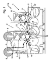
Figur 1- eine Darstellung einer Bogenrotationsdruckmaschine mit einer Fo- lientransfermodul und
Figur 2bis 5- Konfigurationen einer Bogendruckmaschine mit einem Folien- transfermodul.
- FIG. 1
- a representation of a sheet-fed rotary printing machine with a Filientransfermodul and
- FIGS. 2 to 5
- Configurations of a sheet-fed press with a film transfer module.
In
Ein zu beschichtender Druckbogen wird in einem ersten Schritt im Auftragwerk 1 mit einem bildgebenden Klebstoffmuster versehen. Hierzu kann ein Druckwerk einer Offsetdruckmaschine mit Farb- und Feuchtwerken 11, einer Druckplatte auf einem Plattenzylinder 12, einem Drucktuch- oder Gummizylinder 13 und einem Gegendruckzylinder 4 verwendet werden. Gleichfalls sind Auftragwerke in Form von Flexodruck- oder Lackiereinheiten einsetzbar. Der Kleber kann auch in zwei Auftragwerken 1 aufgebracht werden, um seine Wirkung bei unterschiedlichen Untergründen zu verbessern.
Im zweiten Schritt wird gemeinsam mit dem Druckbogen eine Transferfolie 5 unter Pressung durch einen Transferspalt 6 geführt. Ein hierfür verwendetes Folientransfermodul 2 kann ein Druckwerk, ein Lackmodul, eine Basiseinheit oder andersartige Verarbeitungsstation einer Bogenoffsetdruckmaschine sein.
Der Transferspalt 6 im Folientransfermodul 2 wird durch einen Transferzylinder 3 und einen Gegendruckzylinder 4 gebildet. Der Transferzylinder 3 kann einem Drucktuch- oder Formzylinder eines an sich bekannten Offsetdruckwerkes oder Lackmoduls einer Bogenoffsetdruckmaschine entsprechen. Innerhalb des Folientransfermoduls 2 ist eine Bahnführung für Transferfolien 5 dargestellt.In
A sheet to be coated is provided in a first step in the
In the second step, a
The transfer nip 6 in the
Eine Folienvorratsrolle 8 ist dem Folientransfermodul 2 auf der Seite der Bogenzuführung zugeordnet. Die Folienvorratsrolle 8 weist einen Drehantrieb 7 auf. Der Drehantrieb 7 wird zur kontinuierlichen geregelten Zuführung der Transferfolie 5 zum Folientransfermodul 2 benötigt und ist daher steuerbar.
Weiterhin sind im Bereich der Folienzu- und -abführung Leiteinrichtungen 14, wie Umlenk- bzw. Spannwalzen, pneumatisch beaufschlagte Leitmittel, Leitbleche o. ä. vorgesehen. Damit kann die Folienbahn der Transferfolie 5 immer ohne Verzerrungen eben geführt und in gleicher Spannung gegenüber dem Transferzylinder 3 gehalten werden.A
Furthermore, in the field of film feed and
Die Transferfolie 5 kann hierbei um den Transferzylinder 3 herumgeführt werden, wobei die Transferfolie 5 in vorteilhafter Weise nur von einer Seite des Folientransfermoduls 2 aus zum Pressspalt 6 zu- und abführbar ist (siehe strichlierte Darstellung). In einer weiteren Ausführungsform kann die Transferfolie 5 auch im wesentlichen tangential an dem Transferzylinder 3 vorbei oder diese nur in einem kleinen Umfangswinkel umschlingend zum Pressspalt 6 zu- und abgeführt werden. Hierzu wird die Transferfolie 5 von einer Seite des Folientransfermoduls 2 zugeführt und zur gegenüberliegenden Seite des Folientransfermoduls 2 abgeführt. Auf der auslaufseitigen Seite des Druckwerkes ist eine Foliensammelrolle 9 dargestellt, mittels derer verbrauchtes Folienmaterial aufgewickelt wird. Auch hier ist ein Drehantrieb 7 vorgesehen, der steuerbar ist.The
Weiterhin ist vorgesehen im Bereich des Kleberauftrages und des Folientransfers Trockner 16 vorzusehen. Damit kann, z.B. mittels UV-Trocknung, die Kleberschicht mittels eines ersten Trockners 16 (Zwischentrockner I) vorgetrocknet werden, so dass die Nutzschicht der Transferfolie 5 besser anhaftet. Weiterhin kann die Haftwirkung der aufgeprägten Nutzschicht auf dem Druckbogen mittels Einwirkung eines zweiten Trockners 16 (Zwischentrockner II) verbessert werden, indem die Endtrocknung des Klebers zusätzlich beschleunigt wird.Furthermore, it is provided in the area of the adhesive application and the
Für den Transfervorgang der bildgebenden z.B. Nutzschicht von der Transferfolie 5 auf den Druckbogen in dem Transferspalt 6 zwischen dem Transferzylinder 3 und dem Gegendruckzylinder 4 ist die Oberfläche des Transferzylinders 3 mit kompressiblen, dämpfenden Elementen als Pressbespannung 10 versehen.For the transfer process of imaging e.g. Wear layer of the
Wie in
Dazu kann ein zusätzliches Auftragwerk 1' dem Gummizylinder 13 am ersten Gegendruckzylinder 4 vorgeordnet sein. Dann wirkt der Gummizylinder 13 als Presswalze und die Folienbahn 5' wird von diesem durch den Transferspalt geführt.As in
For this purpose, an additional application unit 1 'may be arranged upstream of the
Alternativ hierzu kann eine zusätzliche Presswalze 3' dem Gummizylinder 13 am Gegendruckzylinder 4 nachgeordnet sein. Dann bringt der Gummizylinder 13 wie gewohnt den Kleber auf und es wird von der Presswalze 3' ein zusätzlicher Transferspalt 6' gebildet, durch den die Transferfolie 5' zum Transfer der Folienbeschichtung gegen den Bedruckstoff geführt wird. Hier kann zusätzlich eine Reinigungseinrichtung R' angeordnet sein, um Verunreinigungen (Glitter) der Transferfolie 5' zu beseitigen.Alternatively, an additional press roller 3 'may be arranged downstream of the
Mit der beschriebenen Vorrichtung ist es schon möglich einen Bedruckstoff einseitig bildmäßig zu beschichten oder vollflächig zu versiegeln. Dazu ist die Einrichtung für den Folientransfer in einem den Druckwerken einer Bogendruckmaschine nachgeordneten Druck- oder Lackierwerk angeordnet. Bei einer derartigen Anordnung kann weiterhin die Oberfläche des frischen Druckes geschützt werden.
Für weitere Anwendungsfälle kann innerhalb der Bogenrotationsdruckmaschine der ersten Einrichtung für den Folientransfer auch eine zweite derartige Einrichtung nachgeordnet werden, so dass auch eine doppelte Kaschierung eines Bogens möglich wird.
Weiterhin kann eine Konfiguration vorgesehen werden, die ein erstes Folientransfermodul vor dem ersten eine Farbe oder eine Beschichtung übertragenden Druckwerk und ein zweites Folientransfermodul nach dem letzten Farbe übertragenden Druckwerk vorsieht. Damit kann eine erste Beschichtung direkt auf den Bedruckstoff aufgebracht und eine zweite Beschichtung über dem aufgedruckten Druckbild aufgebracht werden.With the described device, it is already possible to imagewise coat a printing material on one side or to seal it over its entire surface. For this purpose, the device for the film transfer in a printing units of a sheet-fed printing machine downstream printing or coating plant is arranged. With such an arrangement, furthermore, the surface of the fresh print can be protected.
For other applications, within the sheet-fed rotary printing press of the first device for the film transfer, a second such device can be arranged downstream, so that a double lamination of a sheet is possible.
Furthermore, a configuration can be provided which provides a first film transfer module in front of the first color or coating transfer printing unit and a second film transfer module after the last color transferring printing unit. Thus, a first coating can be applied directly to the substrate and a second coating can be applied over the printed image.
Unter Verwendung einer vorstehend beschriebenen Einrichtung zur Durchführung des Kaltfolienprägeverfahrens sind weiterhin auch Verfahren durchführbar, bei deren Anwendung das Beschichten oder auch Mehrfachbeschichten von ein- oder beidseitig zu beschichtenden Druckprodukten innerhalb einer Bogenrotationsdruckmaschine möglich wird.Using a device described above for carrying out the cold foil stamping method, it is also possible to carry out processes in the use of which it is possible to coat or even coat multiple print products to be coated on one or both sides within a sheet-fed rotary printing press.
Dabei kann in vorteilhafter Weise durch die Kombination von Beschichtungseinheiten wie z. B. Lackmodulen, einer Einrichtung zur Bogenwendung sowie Beschichtungsmodulen für eine ein- oder beidseitige Folienapplikation ermöglicht werden. Durch die erfindungsgemäßen Verfahren und Vorrichtungen kann die Herstellung von Effekt- und Funktionsapplikation auch in Verbindung mit einer beidseitigen Bedruckbarkeit des Bedruckstoffes ermöglicht werden.It can be advantageously by the combination of coating units such. As paint modules, a device for sheet turning and coating modules for a single or double-sided film application. By means of the methods and devices according to the invention, the production of effect and functional application can also be made possible in connection with a printability of the printing material on both sides.
In
In den
In
In der gezeigten Konfiguration schließen sich an die Wendeeinrichtung W ein Auftragwerk 1 und ein Beschichtungsmodul 2 an, die auch als integriertes Folientransfermodul FA innerhalb eines Druckwerkes angeordnet sein können. Danach sind bis zum Bogenausleger AU ggf. mehrere weitere Druckwerke D vorgesehen.In the configuration shown, the
Mit einer derartigen Druckmaschine kann also jeder Druckbogen zunächst von seiner Rückseite ein- oder zweifarbig bedruckt oder bedruckt und beschichtet, dann gewendet, dann mit einer kaschierenden oder bildmäßig ausgeführten Folienschicht beschichtet und nachfolgend nochmals mehrfarbig bedruckt werden.With such a printing press, each printed sheet can be printed on one or two colors of its back side or printed and coated, then turned, then coated with a laminating or imagewise executed film layer and subsequently printed again in multiple colors.
In
In der gezeigten Konfiguration sind im Anschluss an die Wendeeinrichtung W bis zum Bogenausleger AU ggf. mehrere weitere Druckwerke D vorgesehen.In
In the configuration shown, several further printing units D are provided following the turning device W to the sheet delivery AU if necessary.
In
Prinzipiell können die beiden ersten Druckwerke für den Kaltfolientransfer genutzt werden, so dass in der ersten Wendeeinrichtung W nach dem zweiten Druckwerk D der Druckbogen umgestülpt und danach rückseitig sechsfarbig bedruckt oder mehrfarbige bedruckt und anderweitig weiterverarbeitet werden kann.In principle, the two first printing units can be used for the cold foil transfer, so that in the first turning device W after the second printing unit D everted the sheet and then printed back six-color or multicolor printed and otherwise processed.
In
In
Mit einer derartigen Druckmaschine kann also jeder Druckbogen zunächst von seiner Rückseite ein- oder zweifarbig bedruckt, dann gewendet, dann mit einer kaschierenden Schicht beschichtet und nachfolgend nochmals mehrfarbig bedruckt werden.With such a printing press, each printed sheet can be printed on its back one or two colors, then turned, then coated with a laminating layer and subsequently printed again in multiple colors.
Weiterhin ergeben sich in derartigen Maschinen weitere Produktionsmöglichkeiten, indem Druckbogen mit optischen oder taktilen Mustern versehen werden, die der Folienbeschichtung unterlegt und durch diese sichtbar oder tastbar sind, oder auch indem über die Folie selbst optische oder taktile Oberflächenmuster aufgebracht werden. Diese Beschichtungsvorgänge können wiederum einseitig oder beidseitig auf unbedruckten oder bedruckten Oberflächen erfolgen.Furthermore, in such machines further production possibilities arise by providing printed sheets with optical or tactile patterns, which are underlaid and visible or palpable by the film coating, or also by applying optical or tactile surface patterns over the film itself. These coating operations can again be done on one side or both sides on unprinted or printed surfaces.
Zur Funktionsverbesserung ist vorgesehen, dass wenigstens der Gegendruckzylinder 4, der in einem einer Wendeeinrichtung W nachgeordneten Druckwerk D angeordnet ist, mit einer speziellen Widerdruckoberfläche versehen ist. Hier trifft nämlich die bereits beschichtete Bogenseite mit der Zylinderoberfläche zusammen und es kann zu so genannten Abschmiereffekten kommen.
Um dem entgegenzuwirken kann die Oberfläche des Gegendruckzylinders 4 mit einer veredelnden Beschichtung versehen sein, so dass eine Annahme von Beschichtungsstoffen vom Druckbogen verhindert wird. Die Beschichtung kann hierfür auch eine Strukturierung aufweisen. Ebenso können veredelnde Beschichtung und Strukturierung kombiniert sein.To improve the function, it is provided that at least the
To counter this, the surface of the
Alternativ zur direkten Anordnung auf der Oberfläche des Gegendruckzylinders 4 kann auch eine so genannte Widerdruckplatte vorgesehen sein, die die veredelnde und/oder strukturierte Beschichtung trägt. Die Widerdruckplatte wird dann entnehmbar an dem Gegendruckzylinder 4 angeordnet.As an alternative to the direct arrangement on the surface of the
Natürlich können auch mehrere oder alle Gegendruckzylinder 4 in den Druckwerken D, die nach einer Wendeeinrichtung W angeordnet sind, mit einer derartigen Beschichtung oder Widerdruckplatte versehen sein.Of course, several or all
Hierbei soll auch eine beidseitige Folienapplikation im Inline- und/oder Offlinebetrieb ermöglicht werden, um die Eigenschaften der Druckprodukte zu verbessern, wobei eine Kaltfolienprägeapplikation in einer Bogenrotations- oder Flexodruckmaschine ermöglicht werden kann.In this case, a double-sided film application in inline and / or offline operation is to be made possible in order to improve the properties of the printed products, with a cold foil embossing application in a sheet-fed or flexographic printing machine can be made possible.
Die Vorrichtung beinhaltet ein Beschichtungsmodul für das Kaltfolientransferverfahren vor und/oder nach einer Wendeeinrichtung innerhalb einer Bogendruckmaschine und ergänzt die beschriebene Verfahrenstechnik in vorteilhafter Weise.The device includes a coating module for the cold foil transfer method before and / or after a turning device within a sheet-fed printing machine and complements the described process engineering in an advantageous manner.
- 11
- Auftragwerkcommissioned
- 22
- Beschichtungswerkcoating plant
- 33
- Presswalzepress roll
- 44
- GegendruckzylinderImpression cylinder
- 55
- Transferfolie / FolienbahnTransfer foil / foil web
- 66
- Transferspalttransfer nip
- 77
- Rollenantriebroller drive
- 88th
- FolienvorratsrolleFilm supply roll
- 99
- FoliensammelrolleFoil composite role
- 1010
- PressbespannungPress covering
- 1111
- Farb-/FeuchtwerkInking / dampening unit
- 1212
- Plattenzylinderplate cylinder
- 1313
- Gummizylinderrubber cylinder
- 1414
- Leiteinrichtungguide
- 1515
- DruckwerksschutzPrinting plant security
- 1616
- Trocknerdryer
- 1717
- Inspektionseinrichtunginspection device
- 1818
- Tänzerwalzedancer roll
- 1'1'
- Auftragwerkcommissioned
- 3'3 '
- Presswalzepress roll
- 5'5 '
- Transferfolie / FolienbahnTransfer foil / foil web
- 6'6 '
- Transferspalttransfer nip
- R'R '
- Reinigungseinrichtungcleaning device
- DD
- Druckwerkprinting unit
- ANAT
- Anlegerinvestor
- AUAU
- Auslegerboom
- FAFA
- FolientransfermodulFoil transfer module
- WW
- Wendeeinrichtungturning device
Claims (7)
- A method for the transfer of imaging or covering layers of a substrate foil on print sheets in a sheet-processing machine, more preferably a sheet-processing rotary printing press, at least with an application system (1) for imaging or areal coating of a print sheet with an adhesive and with at least one coating system (2) for the transferring of imaging or covering layers from the substrate foil onto the printing sheet, wherein in a coating system (2) a transfer gap (6) is formed and the substrate foil along the surface of a pressure roller (3) and with the coated side is placed on to a printing sheet and under pressure can be jointly with the latter guided through the transfer gap (6) so that the imaging and covering layers are adhesively transferred from the substrate foil to the printing sheet in regions provided with adhesive, that each printing sheet on at least one printed or coated or unprinted or uncoated first page in a transfer gap (6) is provided with a foil coating from the substrate foil (5), that each printing sheet before or after the coating is reversed in the sheet-processing machine and that each printing sheet is at least printed and/or coated on the side opposite to the foil coating and/or in a further coating system (2) is provided with a foil coating, characterized in that the printing sheet on a side to be coated with a foil coating from a substrate foil (5) in a transfer gap (6) is provided with a pre-coating comprising a visible or tactual pattern, wherein the adhesive application is performed subject to the inclusion of the areal components of the pre-coating and that the pre-coating is performed in a printing system or varnish module or by means of inkjet printing heads, wherein the printing sheet on a side to be coated from a foil coating from a substrate foil (5) in a transfer gap (6) are provided with a visually or tactually effective pre-coating, wherein the pre-coating is carried out on to the imaging side of the substrate foil (5) in such a manner that the pre-coating together with the imaging layer of the substrate foil (5) is transferred on to the printing sheets in the transfer gap (6).
- The method according to Claim 1, characterized in that printing sheets are at least printed on a first side, in that the printing sheets are reversed in the sheet processing machine and in that the printing sheets are provided with a foil coating from a substrate foil (5) on the side located opposite the printed side in a transfer gap (6).
- The method according to Claim 1, characterized in that printing sheets on a first side are provided with a foil coating from the substrate foil (5) in a transfer gap (6), in that the printing sheets are reversed in the sheet-processing machine and in that the printing sheets are at least printed on the side located opposite the foil coating.
- The method according to Claim 1, characterized in that printing sheets on a first side are provided with a foil coating from the substrate foil (5) in a transfer gap (6), in that the printing sheets are reversed in the sheet-processing machine and in that the printing sheets are provided with a further foil coating in a further transfer gap (6) on the site located opposite the foil coating.
- The method according to Claim 4, characterized in that printing sheets on a first unprinted and coated or printed and coated side are provided with a foil coating in a transfer gap (6), in that the printing sheets are reversed in the sheet-processing machine and in that the printing sheets are provided with an additional foil coating at least in a further transfer gap (6) on the unprinted and coated or printed and coated side located opposite the foil coating.
- The method according to Claim 1, characterized in that printing sheets on a first side are provided with a foil coating from the substrate foil (5) in a transfer gap (6) on to which a coating or a printing image is optionally applied, in that the printing sheets are reversed in the sheet-processing machine and in that the printing sheets on the side located opposite the foil coating are provided with a further foil coating in a further transfer gap (6) onto which foil coating a coating or a printing image is optionally applied.
- The method according to Claim 6, characterized in that printing sheets on a first unprinted and coated or printed and coated side are provided with a foil coating from the substrate foil (5) in a transfer gap, in that the printing sheets are reversed in the sheet-processing machine and in that the printing sheets on the unprinted and coated or printed and coated side located opposite the foil coating are provided with a further foil coating at least in a further transfer gap (6).
Applications Claiming Priority (2)
| Application Number | Priority Date | Filing Date | Title |
|---|---|---|---|
| DE102006061442 | 2006-12-23 | ||
| PCT/EP2007/010507 WO2008077455A1 (en) | 2006-12-23 | 2007-12-04 | Multi-color printing machine having a foil transfer device |
Publications (2)
| Publication Number | Publication Date |
|---|---|
| EP2106346A1 EP2106346A1 (en) | 2009-10-07 |
| EP2106346B1 true EP2106346B1 (en) | 2010-07-07 |
Family
ID=39185854
Family Applications (1)
| Application Number | Title | Priority Date | Filing Date |
|---|---|---|---|
| EP07856349A Not-in-force EP2106346B1 (en) | 2006-12-23 | 2007-12-04 | Multi-color printing machine having a foil transfer device |
Country Status (7)
| Country | Link |
|---|---|
| US (1) | US20100078121A1 (en) |
| EP (1) | EP2106346B1 (en) |
| JP (1) | JP2010514588A (en) |
| CN (1) | CN101573237A (en) |
| AT (1) | ATE473102T1 (en) |
| DE (1) | DE502007004355D1 (en) |
| WO (1) | WO2008077455A1 (en) |
Families Citing this family (5)
| Publication number | Priority date | Publication date | Assignee | Title |
|---|---|---|---|---|
| JP5284603B2 (en) * | 2007-05-31 | 2013-09-11 | 株式会社小森コーポレーション | Sheet-fed printing machine |
| JP5522714B2 (en) * | 2009-05-27 | 2014-06-18 | 株式会社朝日プリンテック | Printing system |
| CN106945384A (en) * | 2016-01-06 | 2017-07-14 | 浙江德钜铝业有限公司 | A kind of Sai Yin get combination of rigidity and flexibility color coating metallic plate and its finishing system and coating process |
| CN108340663B (en) * | 2017-01-23 | 2020-02-07 | 长胜纺织科技发展(上海)有限公司 | Paperless transfer printing machine |
| CN107757094A (en) * | 2017-10-13 | 2018-03-06 | 厦门美润合悦卫生材料有限公司 | A kind of frontal waist plaster printing is coated with release all-in-one |
Family Cites Families (11)
| Publication number | Priority date | Publication date | Assignee | Title |
|---|---|---|---|---|
| FR2672008B1 (en) | 1991-01-29 | 1994-09-02 | Cros Jean Pierre | PRINTING MATERIAL AND METHOD AND INSTALLATION FOR PRINTING USING THE SAME. |
| DE4110801C1 (en) * | 1991-04-04 | 1992-05-27 | Kurt 4040 Neuss De Lappe | |
| US5603259A (en) * | 1993-08-31 | 1997-02-18 | Crown Roll Leaf, Inc. | In-line cold foil transfer process and apparatus |
| DE29918488U1 (en) * | 1999-10-20 | 1999-12-30 | Roland Man Druckmasch | Sheet-fed rotary printing machine with printing units for multi-color printing and at least one coating unit |
| CA2489388C (en) * | 2002-06-11 | 2009-09-08 | Man Roland Druckmaschinen Ag | Applicator device for a printing/varnishing unit in a processing machine |
| DE10351305A1 (en) * | 2003-10-31 | 2005-05-25 | Man Roland Druckmaschinen Ag | Combined printing machine |
| DE102005011568A1 (en) * | 2004-04-13 | 2005-11-17 | Man Roland Druckmaschinen Ag | Coating method for printed sheet in sheet processing machine involves figure moderate coating e.g. metallic coating of printed sheet with glue with coating head whereby impression cylinder and press roller are built in coating module |
| ES2332230T3 (en) * | 2004-04-13 | 2010-01-29 | Manroland Ag | SUPPORT BASE FOR STAMPING DEVICE. |
| PL1700692T3 (en) | 2005-03-10 | 2016-05-31 | manroland sheetfed GmbH | Device for transferring imaging layers from a carrier sheet to printing sheets |
| DE102005060589A1 (en) * | 2005-12-17 | 2007-06-21 | Man Roland Druckmaschinen Ag | Laminating by means of a stamping device |
| DE102006009633A1 (en) * | 2006-03-02 | 2007-09-06 | Heidelberger Druckmaschinen Ag | Film transfer device with variable film path guidance |
-
2007
- 2007-12-04 EP EP07856349A patent/EP2106346B1/en not_active Not-in-force
- 2007-12-04 AT AT07856349T patent/ATE473102T1/en active
- 2007-12-04 CN CNA2007800434901A patent/CN101573237A/en active Pending
- 2007-12-04 US US12/516,326 patent/US20100078121A1/en not_active Abandoned
- 2007-12-04 JP JP2009541813A patent/JP2010514588A/en not_active Withdrawn
- 2007-12-04 WO PCT/EP2007/010507 patent/WO2008077455A1/en active Application Filing
- 2007-12-04 DE DE502007004355T patent/DE502007004355D1/en active Active
Also Published As
| Publication number | Publication date |
|---|---|
| EP2106346A1 (en) | 2009-10-07 |
| DE502007004355D1 (en) | 2010-08-19 |
| WO2008077455A1 (en) | 2008-07-03 |
| JP2010514588A (en) | 2010-05-06 |
| US20100078121A1 (en) | 2010-04-01 |
| ATE473102T1 (en) | 2010-07-15 |
| CN101573237A (en) | 2009-11-04 |
Similar Documents
| Publication | Publication Date | Title |
|---|---|---|
| EP1940624B1 (en) | Method and printing machine for the production of packaging and promotional materials | |
| EP1839903B1 (en) | Embossing coating for metallic printing material | |
| EP1737658B1 (en) | Method for applying a film | |
| DE102006056901A1 (en) | Embossing coating for film substrates | |
| DE102005021185A1 (en) | Opaque white application method e.g. for effect coatings on print substrate, providing over print after covering is dried and hardened so that the coating application can be printed by several ink jet print heads directly by printing | |
| EP1700692B1 (en) | Device for transferring imaging layers from a carrier sheet to printing sheets | |
| EP1976700A1 (en) | Overprintable embossing coating | |
| DE102005062497A1 (en) | Device for film coating | |
| DE102006015249A1 (en) | Device for transfer of picture generating layers of transfer foil, has coating module as assembly unit with device for guiding sheet of transfer foil to transfer gap in and out of transfer gap and coating module is assigned to coating head | |
| EP2106346B1 (en) | Multi-color printing machine having a foil transfer device | |
| EP2121327B1 (en) | Cold film application and simultaneous embossing | |
| EP1798033A2 (en) | Lamination using an embossing device | |
| EP1880848A2 (en) | Transfer device and method using an embossing device | |
| DE102007058285A1 (en) | Carrier foil's imaging or covering and/or overlapping layers transferring method for e.g. sheet-fed rotary printing machine, involves printing and/or coating printed sheet on side opposite to foil coating and/or providing sheet with coating | |
| EP1700694A2 (en) | Method of embossing for corrugated cardboard in a sheet-fed printing press and associated device | |
| WO2009053316A2 (en) | Stamping coating for film printing substrates | |
| DE102004063189A1 (en) | Embossing device for image printing applies and transfers adhesive in single printing unit of printing press | |
| DE102006048521A1 (en) | Fabrication method for packaging- and advertising-material, involves generating print-image on printing sheet with inclusion of foil image | |
| EP1700693A2 (en) | Method for embossing and assiciated device for printing material with structured surface in a sheet-fed printing press | |
| DE102006061663A1 (en) | Sheet-fed printing machine with film transfer device | |
| DE102004061952A1 (en) | Method for laminating | |
| EP1972443A2 (en) | Device for transferring imaging layers | |
| DE102008054411A1 (en) | Device for transferring metallized layer from transfer film to printing sheet in sheet-fed offset printing machine, has applicator with adhesive supply device for supplying adhesive, and adhesive reservoir in connection with squeegee device | |
| EP2075130A2 (en) | Coating device with short inking system |
Legal Events
| Date | Code | Title | Description |
|---|---|---|---|
| PUAI | Public reference made under article 153(3) epc to a published international application that has entered the european phase |
Free format text: ORIGINAL CODE: 0009012 |
|
| 17P | Request for examination filed |
Effective date: 20090723 |
|
| AK | Designated contracting states |
Kind code of ref document: A1 Designated state(s): AT BE BG CH CY CZ DE DK EE ES FI FR GB GR HU IE IS IT LI LT LU LV MC MT NL PL PT RO SE SI SK TR |
|
| 17Q | First examination report despatched |
Effective date: 20091112 |
|
| GRAP | Despatch of communication of intention to grant a patent |
Free format text: ORIGINAL CODE: EPIDOSNIGR1 |
|
| DAX | Request for extension of the european patent (deleted) | ||
| GRAS | Grant fee paid |
Free format text: ORIGINAL CODE: EPIDOSNIGR3 |
|
| GRAA | (expected) grant |
Free format text: ORIGINAL CODE: 0009210 |
|
| AK | Designated contracting states |
Kind code of ref document: B1 Designated state(s): AT BE BG CH CY CZ DE DK EE ES FI FR GB GR HU IE IS IT LI LT LU LV MC MT NL PL PT RO SE SI SK TR |
|
| REG | Reference to a national code |
Ref country code: GB Ref legal event code: FG4D Free format text: NOT ENGLISH |
|
| REG | Reference to a national code |
Ref country code: CH Ref legal event code: EP |
|
| REG | Reference to a national code |
Ref country code: IE Ref legal event code: FG4D |
|
| REF | Corresponds to: |
Ref document number: 502007004355 Country of ref document: DE Date of ref document: 20100819 Kind code of ref document: P |
|
| REG | Reference to a national code |
Ref country code: NL Ref legal event code: VDEP Effective date: 20100707 |
|
| PG25 | Lapsed in a contracting state [announced via postgrant information from national office to epo] |
Ref country code: SI Free format text: LAPSE BECAUSE OF FAILURE TO SUBMIT A TRANSLATION OF THE DESCRIPTION OR TO PAY THE FEE WITHIN THE PRESCRIBED TIME-LIMIT Effective date: 20100707 |
|
| LTIE | Lt: invalidation of european patent or patent extension |
Effective date: 20100707 |
|
| PG25 | Lapsed in a contracting state [announced via postgrant information from national office to epo] |
Ref country code: NL Free format text: LAPSE BECAUSE OF FAILURE TO SUBMIT A TRANSLATION OF THE DESCRIPTION OR TO PAY THE FEE WITHIN THE PRESCRIBED TIME-LIMIT Effective date: 20100707 Ref country code: FI Free format text: LAPSE BECAUSE OF FAILURE TO SUBMIT A TRANSLATION OF THE DESCRIPTION OR TO PAY THE FEE WITHIN THE PRESCRIBED TIME-LIMIT Effective date: 20100707 Ref country code: LT Free format text: LAPSE BECAUSE OF FAILURE TO SUBMIT A TRANSLATION OF THE DESCRIPTION OR TO PAY THE FEE WITHIN THE PRESCRIBED TIME-LIMIT Effective date: 20100707 |
|
| REG | Reference to a national code |
Ref country code: IE Ref legal event code: FD4D |
|
| PG25 | Lapsed in a contracting state [announced via postgrant information from national office to epo] |
Ref country code: CY Free format text: LAPSE BECAUSE OF FAILURE TO SUBMIT A TRANSLATION OF THE DESCRIPTION OR TO PAY THE FEE WITHIN THE PRESCRIBED TIME-LIMIT Effective date: 20100707 Ref country code: BG Free format text: LAPSE BECAUSE OF FAILURE TO SUBMIT A TRANSLATION OF THE DESCRIPTION OR TO PAY THE FEE WITHIN THE PRESCRIBED TIME-LIMIT Effective date: 20101007 Ref country code: PL Free format text: LAPSE BECAUSE OF FAILURE TO SUBMIT A TRANSLATION OF THE DESCRIPTION OR TO PAY THE FEE WITHIN THE PRESCRIBED TIME-LIMIT Effective date: 20100707 Ref country code: IS Free format text: LAPSE BECAUSE OF FAILURE TO SUBMIT A TRANSLATION OF THE DESCRIPTION OR TO PAY THE FEE WITHIN THE PRESCRIBED TIME-LIMIT Effective date: 20101107 Ref country code: PT Free format text: LAPSE BECAUSE OF FAILURE TO SUBMIT A TRANSLATION OF THE DESCRIPTION OR TO PAY THE FEE WITHIN THE PRESCRIBED TIME-LIMIT Effective date: 20101108 |
|
| PG25 | Lapsed in a contracting state [announced via postgrant information from national office to epo] |
Ref country code: GR Free format text: LAPSE BECAUSE OF FAILURE TO SUBMIT A TRANSLATION OF THE DESCRIPTION OR TO PAY THE FEE WITHIN THE PRESCRIBED TIME-LIMIT Effective date: 20101008 Ref country code: SE Free format text: LAPSE BECAUSE OF FAILURE TO SUBMIT A TRANSLATION OF THE DESCRIPTION OR TO PAY THE FEE WITHIN THE PRESCRIBED TIME-LIMIT Effective date: 20100707 Ref country code: LV Free format text: LAPSE BECAUSE OF FAILURE TO SUBMIT A TRANSLATION OF THE DESCRIPTION OR TO PAY THE FEE WITHIN THE PRESCRIBED TIME-LIMIT Effective date: 20100707 |
|
| PG25 | Lapsed in a contracting state [announced via postgrant information from national office to epo] |
Ref country code: DK Free format text: LAPSE BECAUSE OF FAILURE TO SUBMIT A TRANSLATION OF THE DESCRIPTION OR TO PAY THE FEE WITHIN THE PRESCRIBED TIME-LIMIT Effective date: 20100707 Ref country code: IE Free format text: LAPSE BECAUSE OF FAILURE TO SUBMIT A TRANSLATION OF THE DESCRIPTION OR TO PAY THE FEE WITHIN THE PRESCRIBED TIME-LIMIT Effective date: 20100707 |
|
| PLBE | No opposition filed within time limit |
Free format text: ORIGINAL CODE: 0009261 |
|
| STAA | Information on the status of an ep patent application or granted ep patent |
Free format text: STATUS: NO OPPOSITION FILED WITHIN TIME LIMIT |
|
| PG25 | Lapsed in a contracting state [announced via postgrant information from national office to epo] |
Ref country code: EE Free format text: LAPSE BECAUSE OF FAILURE TO SUBMIT A TRANSLATION OF THE DESCRIPTION OR TO PAY THE FEE WITHIN THE PRESCRIBED TIME-LIMIT Effective date: 20100707 Ref country code: RO Free format text: LAPSE BECAUSE OF FAILURE TO SUBMIT A TRANSLATION OF THE DESCRIPTION OR TO PAY THE FEE WITHIN THE PRESCRIBED TIME-LIMIT Effective date: 20100707 Ref country code: IT Free format text: LAPSE BECAUSE OF FAILURE TO SUBMIT A TRANSLATION OF THE DESCRIPTION OR TO PAY THE FEE WITHIN THE PRESCRIBED TIME-LIMIT Effective date: 20100707 Ref country code: CZ Free format text: LAPSE BECAUSE OF FAILURE TO SUBMIT A TRANSLATION OF THE DESCRIPTION OR TO PAY THE FEE WITHIN THE PRESCRIBED TIME-LIMIT Effective date: 20100707 Ref country code: SK Free format text: LAPSE BECAUSE OF FAILURE TO SUBMIT A TRANSLATION OF THE DESCRIPTION OR TO PAY THE FEE WITHIN THE PRESCRIBED TIME-LIMIT Effective date: 20100707 |
|
| 26N | No opposition filed |
Effective date: 20110408 |
|
| BERE | Be: lapsed |
Owner name: MANROLAND A.G. Effective date: 20101231 |
|
| PG25 | Lapsed in a contracting state [announced via postgrant information from national office to epo] |
Ref country code: ES Free format text: LAPSE BECAUSE OF FAILURE TO SUBMIT A TRANSLATION OF THE DESCRIPTION OR TO PAY THE FEE WITHIN THE PRESCRIBED TIME-LIMIT Effective date: 20101018 |
|
| REG | Reference to a national code |
Ref country code: DE Ref legal event code: R097 Ref document number: 502007004355 Country of ref document: DE Effective date: 20110408 |
|
| PG25 | Lapsed in a contracting state [announced via postgrant information from national office to epo] |
Ref country code: MC Free format text: LAPSE BECAUSE OF NON-PAYMENT OF DUE FEES Effective date: 20101231 |
|
| REG | Reference to a national code |
Ref country code: FR Ref legal event code: ST Effective date: 20110831 |
|
| PG25 | Lapsed in a contracting state [announced via postgrant information from national office to epo] |
Ref country code: BE Free format text: LAPSE BECAUSE OF NON-PAYMENT OF DUE FEES Effective date: 20101231 |
|
| PG25 | Lapsed in a contracting state [announced via postgrant information from national office to epo] |
Ref country code: FR Free format text: LAPSE BECAUSE OF NON-PAYMENT OF DUE FEES Effective date: 20110103 |
|
| PG25 | Lapsed in a contracting state [announced via postgrant information from national office to epo] |
Ref country code: MT Free format text: LAPSE BECAUSE OF FAILURE TO SUBMIT A TRANSLATION OF THE DESCRIPTION OR TO PAY THE FEE WITHIN THE PRESCRIBED TIME-LIMIT Effective date: 20100707 |
|
| REG | Reference to a national code |
Ref country code: CH Ref legal event code: PL |
|
| GBPC | Gb: european patent ceased through non-payment of renewal fee |
Effective date: 20111204 |
|
| PG25 | Lapsed in a contracting state [announced via postgrant information from national office to epo] |
Ref country code: LU Free format text: LAPSE BECAUSE OF NON-PAYMENT OF DUE FEES Effective date: 20101204 Ref country code: HU Free format text: LAPSE BECAUSE OF FAILURE TO SUBMIT A TRANSLATION OF THE DESCRIPTION OR TO PAY THE FEE WITHIN THE PRESCRIBED TIME-LIMIT Effective date: 20110108 |
|
| PG25 | Lapsed in a contracting state [announced via postgrant information from national office to epo] |
Ref country code: LI Free format text: LAPSE BECAUSE OF NON-PAYMENT OF DUE FEES Effective date: 20111231 Ref country code: CH Free format text: LAPSE BECAUSE OF NON-PAYMENT OF DUE FEES Effective date: 20111231 Ref country code: GB Free format text: LAPSE BECAUSE OF NON-PAYMENT OF DUE FEES Effective date: 20111204 Ref country code: TR Free format text: LAPSE BECAUSE OF FAILURE TO SUBMIT A TRANSLATION OF THE DESCRIPTION OR TO PAY THE FEE WITHIN THE PRESCRIBED TIME-LIMIT Effective date: 20100707 |
|
| REG | Reference to a national code |
Ref country code: DE Ref legal event code: R081 Ref document number: 502007004355 Country of ref document: DE Owner name: MANROLAND SHEETFED GMBH, DE Free format text: FORMER OWNER: MANROLAND AG, 63075 OFFENBACH, DE Effective date: 20130617 |
|
| REG | Reference to a national code |
Ref country code: AT Ref legal event code: MM01 Ref document number: 473102 Country of ref document: AT Kind code of ref document: T Effective date: 20121204 |
|
| PG25 | Lapsed in a contracting state [announced via postgrant information from national office to epo] |
Ref country code: AT Free format text: LAPSE BECAUSE OF NON-PAYMENT OF DUE FEES Effective date: 20121204 |
|
| PGFP | Annual fee paid to national office [announced via postgrant information from national office to epo] |
Ref country code: DE Payment date: 20201211 Year of fee payment: 14 |
|
| REG | Reference to a national code |
Ref country code: DE Ref legal event code: R119 Ref document number: 502007004355 Country of ref document: DE |
|
| PG25 | Lapsed in a contracting state [announced via postgrant information from national office to epo] |
Ref country code: DE Free format text: LAPSE BECAUSE OF NON-PAYMENT OF DUE FEES Effective date: 20220701 |