EP2106313B1 - Tool head for a pipe-cutting machine - Google Patents
Tool head for a pipe-cutting machine Download PDFInfo
- Publication number
- EP2106313B1 EP2106313B1 EP07846294A EP07846294A EP2106313B1 EP 2106313 B1 EP2106313 B1 EP 2106313B1 EP 07846294 A EP07846294 A EP 07846294A EP 07846294 A EP07846294 A EP 07846294A EP 2106313 B1 EP2106313 B1 EP 2106313B1
- Authority
- EP
- European Patent Office
- Prior art keywords
- support
- tool head
- wedge
- wall
- thrusting
- Prior art date
- Legal status (The legal status is an assumption and is not a legal conclusion. Google has not performed a legal analysis and makes no representation as to the accuracy of the status listed.)
- Active
Links
- 239000000463 material Substances 0.000 claims description 33
- 238000000034 method Methods 0.000 claims description 10
- 238000003754 machining Methods 0.000 claims description 9
- 238000010276 construction Methods 0.000 claims description 2
- 230000005540 biological transmission Effects 0.000 claims 1
- 238000005553 drilling Methods 0.000 description 3
- 230000003628 erosive effect Effects 0.000 description 3
- 239000007787 solid Substances 0.000 description 2
- 241000985128 Cladium mariscus Species 0.000 description 1
- 230000008878 coupling Effects 0.000 description 1
- 238000010168 coupling process Methods 0.000 description 1
- 238000005859 coupling reaction Methods 0.000 description 1
- 230000002349 favourable effect Effects 0.000 description 1
- 239000008384 inner phase Substances 0.000 description 1
- 230000035515 penetration Effects 0.000 description 1
- 238000003825 pressing Methods 0.000 description 1
Images


Classifications
-
- B—PERFORMING OPERATIONS; TRANSPORTING
- B23—MACHINE TOOLS; METAL-WORKING NOT OTHERWISE PROVIDED FOR
- B23D—PLANING; SLOTTING; SHEARING; BROACHING; SAWING; FILING; SCRAPING; LIKE OPERATIONS FOR WORKING METAL BY REMOVING MATERIAL, NOT OTHERWISE PROVIDED FOR
- B23D21/00—Machines or devices for shearing or cutting tubes
- B23D21/14—Machines or devices for shearing or cutting tubes cutting inside the tube
-
- B—PERFORMING OPERATIONS; TRANSPORTING
- B23—MACHINE TOOLS; METAL-WORKING NOT OTHERWISE PROVIDED FOR
- B23B—TURNING; BORING
- B23B29/00—Holders for non-rotary cutting tools; Boring bars or boring heads; Accessories for tool holders
- B23B29/03—Boring heads
- B23B29/034—Boring heads with tools moving radially, e.g. for making chamfers or undercuttings
- B23B29/03432—Boring heads with tools moving radially, e.g. for making chamfers or undercuttings radially adjustable during manufacturing
- B23B29/03446—Boring heads with tools moving radially, e.g. for making chamfers or undercuttings radially adjustable during manufacturing by means of inclined planes
- B23B29/03453—Grooving tool
-
- B—PERFORMING OPERATIONS; TRANSPORTING
- B23—MACHINE TOOLS; METAL-WORKING NOT OTHERWISE PROVIDED FOR
- B23B—TURNING; BORING
- B23B2270/00—Details of turning, boring or drilling machines, processes or tools not otherwise provided for
- B23B2270/20—Internally located features, machining or gripping of internal surfaces
- B23B2270/205—Machining or gripping both internal and external surfaces
-
- Y—GENERAL TAGGING OF NEW TECHNOLOGICAL DEVELOPMENTS; GENERAL TAGGING OF CROSS-SECTIONAL TECHNOLOGIES SPANNING OVER SEVERAL SECTIONS OF THE IPC; TECHNICAL SUBJECTS COVERED BY FORMER USPC CROSS-REFERENCE ART COLLECTIONS [XRACs] AND DIGESTS
- Y10—TECHNICAL SUBJECTS COVERED BY FORMER USPC
- Y10T—TECHNICAL SUBJECTS COVERED BY FORMER US CLASSIFICATION
- Y10T407/00—Cutters, for shaping
- Y10T407/22—Cutters, for shaping including holder having seat for inserted tool
- Y10T407/2222—Tool adjustable relative to holder
-
- Y—GENERAL TAGGING OF NEW TECHNOLOGICAL DEVELOPMENTS; GENERAL TAGGING OF CROSS-SECTIONAL TECHNOLOGIES SPANNING OVER SEVERAL SECTIONS OF THE IPC; TECHNICAL SUBJECTS COVERED BY FORMER USPC CROSS-REFERENCE ART COLLECTIONS [XRACs] AND DIGESTS
- Y10—TECHNICAL SUBJECTS COVERED BY FORMER USPC
- Y10T—TECHNICAL SUBJECTS COVERED BY FORMER US CLASSIFICATION
- Y10T82/00—Turning
- Y10T82/10—Process of turning
-
- Y—GENERAL TAGGING OF NEW TECHNOLOGICAL DEVELOPMENTS; GENERAL TAGGING OF CROSS-SECTIONAL TECHNOLOGIES SPANNING OVER SEVERAL SECTIONS OF THE IPC; TECHNICAL SUBJECTS COVERED BY FORMER USPC CROSS-REFERENCE ART COLLECTIONS [XRACs] AND DIGESTS
- Y10—TECHNICAL SUBJECTS COVERED BY FORMER USPC
- Y10T—TECHNICAL SUBJECTS COVERED BY FORMER US CLASSIFICATION
- Y10T82/00—Turning
- Y10T82/12—Radially moving rotating tool inside bore
-
- Y—GENERAL TAGGING OF NEW TECHNOLOGICAL DEVELOPMENTS; GENERAL TAGGING OF CROSS-SECTIONAL TECHNOLOGIES SPANNING OVER SEVERAL SECTIONS OF THE IPC; TECHNICAL SUBJECTS COVERED BY FORMER USPC CROSS-REFERENCE ART COLLECTIONS [XRACs] AND DIGESTS
- Y10—TECHNICAL SUBJECTS COVERED BY FORMER USPC
- Y10T—TECHNICAL SUBJECTS COVERED BY FORMER US CLASSIFICATION
- Y10T82/00—Turning
- Y10T82/22—Portable lathe for pipe turning
Definitions
- the invention relates to a tool head, a machine for processing the ends of a bar-shaped profile material, and a method for processing the ends of a bar-shaped profile material.
- Pipe cutting machines and tool heads intended for them are known in the art.
- Conventional pipe cutting machines have a tool head with one or more cutting edges and a clamping device for a pipe to be machined, which is arranged positionally fixed in the longitudinal direction directly in front of the rotatable tool relative to the machine.
- the tool head is set in rotation and moved in the longitudinal direction against the end face of the tube.
- a disadvantage of the tool holder described is its unsatisfactory precision.
- a disadvantage of the described pipe cutting machines is the fact that the cutting tools are not controllable movable in the radial direction. Thus, it is particularly not possible to introduce grooves, recesses and the like behind the end face in the pipe inside or pipe outer wall.
- the tool head according to the invention has a housing in which at least one thrust wedge is provided, which is arranged to be movable back and forth in the longitudinal direction in a first toothed guide.
- the first toothed guide has two tooth profiles which correspond with one another and slide back and forth in the longitudinal direction.
- a first tooth profile is applied to an outer wall of the thrust wedge, while a corresponding first tooth profile is provided on an inner wall of the associated thrust wedge guide in a housing.
- the tooth guide generates an enlarged contact surface between the thrust wedge and the housing.
- Each of the thrust wedges is associated in each case with a second tooth guide in a direction transverse to the longitudinal direction arranged movable support in the housing.
- the second tooth guide of the support the same applies mutatis mutandis to the first tooth guide of the thrust wedge.
- the externally mounted on the support second tooth profile cooperates with a recessed in a wedge guide inserted inside wall corresponding second tooth profile. Due to the enlargement of the contact surface, a tooth guide with high quality is also produced here.
- the thrust wedge and the associated support are slidably in contact with each other via an inclined contact surface, and longitudinal movement of the thrust wedge is converted via the inclined contact surface into transverse movement of the associated support.
- the oblique contact surface is preferably smooth over its entire extent and formed with a constant pitch.
- the support has a transversely extending support arm.
- the transverse direction is perpendicular to the longitudinal direction and in the radial direction of the cutting tool.
- the cutting tool attached to the support is movable in the radial direction.
- the tool head is in rapid rotational motion about the longitudinal axis.
- the tool head according to the invention makes it possible to adjust the cutting tools radially controlled during the rotational movement.
- the tool head is mounted on a rotary feedthrough, which has three juxtaposed longitudinally sliding rods.
- the ends of the push rods can contact the thrust keys and form an operative connection with them.
- a thrust force is transmitted through the push rod to the associated thrust wedge.
- the at least one pusher and the at least one support each associated with a return spring
- the pusher is pushed by a thrust force on the tool head against the longitudinal direction outwardly projecting pusher arm on an end face of the tool head into the tool head, while the same pusher wedge by the return spring automatically reset against the longitudinal direction.
- the cutting tool makes it possible, for example, to introduce radial undercuts on an outer wall of a rod-shaped, circular cross-section profile material.
- the cutting tools are first moved radially outward, set the tool head in rotation and then moved in the longitudinal direction to the end face of the rod-shaped profile material, so far that the cutting tools behind the end of the bar-shaped profile material. Only now, the cutting tool controlled by inward pressure on the at least one thrust wedge arm moved inward and thus a Inserted from the end face of the profile material rear rotation in the outer wall.
- a plurality of supports are provided star-shaped in a cross section perpendicular to the longitudinal direction and each support has a transverse support arm associated therewith.
- the support arms are arranged crossing each other in a longitudinal direction.
- the housing is formed in a cross-section perpendicular to the longitudinal direction substantially circular, and the at least one pusher has at each other on the pusher wedge opposite, radially extending outer walls on a first outer tooth profile, with a first inner tooth profile on an inner wall of the pusher guide as the first Tooth guide cooperates.
- the radial outer walls of a rectangular in cross section to the longitudinal direction of the thrust wedge are provided with a longitudinally extending first outer tooth profile.
- the corresponding first inner tooth profile is applied to the inner wall of the thrust wedge guide in the housing.
- All tooth profiles are manufactured in a particularly exact manner by wire EDM. Wire eroding requires that the tooth profiles extend over the entire extent of the associated guides of the component.
- the at least one support on opposite radially extending walls each have a second outer tooth profile, which cooperates with a second inner tooth profile on an inner wall of the support guide to the second tooth guide.
- the second tooth guide is preferably guided radially through the housing perpendicular to the longitudinal direction.
- the outer second tooth profile conveniently extends over the entire radial extent of the support arm. Due to the additional second toothing of the support a particularly high guidance accuracy and quality is achieved.
- the at least one pusher has a constant height.
- Under construction height is understood here as the extent of the thrust wedge perpendicular to the longitudinal direction and perpendicular to the radius of the tool head.
- the sliding wedges are identical.
- the part of the at least one support provided in the housing likewise has a constant overall height along its entire extent.
- the thrust wedge temporarily projects into the support guide during operation.
- the height of the thrust wedge to the tooth depth of the second tooth profile is smaller than the height of the support.
- Support and pusher are automatically recoverable in a cost-effective embodiment of the invention by appropriately sized return springs.
- the stated object is achieved by a machine having a tool head described above.
- a machine which enables a corresponding control of the tool head has, for example, a rotary feedthrough.
- the object is achieved by a method for machining ends of a bar-shaped profile material by introducing a radial undercut into a wall of the profile material.
- a method for machining ends of a bar-shaped profile material by introducing a radial undercut into a wall of the profile material.
- Such a method can be carried out by a tool head described above and a machine described above.
- the at least one support for machining a profile material outer wall is first moved radially outward or initially to work radially inward for machining a profile inner wall.
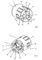
- the in Fig. 1 shown tool head 10 has a cross-section perpendicular to a longitudinal direction L substantially circular housing 11 formed.
- the tool head 10 is rotatably mounted in operation about a longitudinal axis L aligned centrally through the tool head 10 guided rotation axis in a machine for cutting pieces of a rod-shaped profile material, in particular a pipe cutting machine, and is driven about this axis with up to 1000 revolutions per minute ,
- the tool head 10 has three radially movable supports 21, 22, 23.
- the three radial directions R1, R2, R3 are arranged at an angle of 120 ° to each other and perpendicular to the longitudinal direction L.
- each support 21, 22, 23 In operation, on the outside of each support 21, 22, 23, a respective (not shown) cutting tool is fixedly mounted in position relative to it.
- the adjustment length of each support 21, 22, 23 is about 10 mm along the associated radii direction R1, R2, R3.
- the tool head is NC-controlled in operation by a rotary feedthrough of the pipe cutting machine.
- the in Fig. 1 shown tool head 10 is intended to edit the ends of metallic profiles, in particular tubes or circular solid profiles, with the (not shown) cutting tools.
- the cutting tools are interchangeably mounted and they can be different.
- the tool head 10 has three holes 16, 17, 18 which are made through the tool head 10 in the longitudinal direction L for screws for fastening to a rotary feedthrough driving the tool head.
- Fig. 2 shows the tool head 10 according to Fig. 1 in a rear view.
- the pipe to be machined is arranged in the longitudinal direction L concentric with the tool head 10 so that the three cutting tools (not shown) can machine the end of the pipe.
- the tool head 10 is displaced in the longitudinal direction L in the direction of the pipe end clamped in front of the tool head 10, and the three cutting tools take forward predetermined machining operations at the pipe end by means of rotational movement.
- FIG. 2 shown back view shows three thrust cam arms 41, 42, 43 of three slidable in the longitudinal direction L in the housing 11 arranged thrust washers 31, 32, 33.
- the tool head 10 is controlled via a (not shown) three push rods having rotary union, the one a sufficient rotational movement about the longitudinal axis L is available, which is transmitted to the fixed relative to the rotary feedthrough fixed tool head 10 and additionally provides three individually controllable push rods available that by pressure loads on three of each push rod associated pusher wedge 31, 32, 33 controlling this move.
- the rotary feedthrough exerts operation-controlled pressure individually on each of the three sliding-cone arms 41, 42, 43 via a respective flat contact surface 51, 52, 53.
- the pusher wedge 31, 32, 33 is displaced in the longitudinal direction L towards the pipe to be processed.
- the associated thrust wedge 31, 32, 33 automatically returns due to a return spring 61, 62, 63 provided in the housing 11.
- Fig. 3 shows the three pushers 31, 32, 33 and three supports 21, 22, 23 in their relative arrangement to each other.
- the three thrust keys 31, 32, 33 are of identical design and offset from one another about the longitudinal axis L of the tool head 10 at an angle of 120 °.
- Each thrust wedge 31, 32, 33 has the associated thrust wedge arm 41, 42, 43 at the end facing the rotary leadthrough and on the support 21, 22, 23 facing the end of a chamfered surface 71, 72, 73.
- the beveled surface 71 has a uniform slope with respect to the longitudinal axis L.
- each of the thrust wedges 31, 32, 33 has a recess for its associated return spring 61, 62, 63.
- the one end of the restoring spring 61, 62, 63 is fixedly connected to the thrust wedge 31, 32, 33, while the other end of the return spring 61, 62, 63 is fixedly connected to the housing 11 in connection.
- Each of the thrust wedges 31, 32, 33 has two oppositely extending in the radial direction outer walls, which are each completely provided with a longitudinally extending tooth profile 81, 82, 83.
- the tooth profile 81, 82, 83 is introduced into the outer walls by means of a wire eroding method.
- the provided perpendicular to the longitudinal axis L and perpendicular to the radial direction height of each of the thrust keys 31, 32, 33 is constant over the entire longitudinal and radial extent of the thrust wedge 31, 33, 33.
- the oblique contact surface 71, 72, 73 of the thrust wedge 31, 32, 33 has a constant slope over its entire extent. She is in constant and sliding contact with one corresponding inclined contact surface 71. 72. 73 of the thrust wedge 31, 32. 33 associated support 21, 22, 23rd
- Each support 21, 22, 23 has according to Fig. 4 each a mounting plate 91, 92, 93 for a cutting tool. The cutting tools are not shown.
- the supports 21, 22, 23 are arranged exactly in the radial direction of the tool head 10 back and forth in the tool head 10. The inward radial movement of the support 21, 22, 23 is caused by an over the thrust wedge 31, 32, 33 on the support 21, 22, 23 applied compressive force by the the support 21, 22, 23 associated pusher 31, 32, 33 is pressed into the interior of the housing 10. Via the two oblique contact surfaces 71, 72, 73 between thrust wedge 31, 32, 33 and associated support 21, 22, 23, a force on the thrust wedge 31. 32, 33 is deflected in the radial direction.
- each support 21, 22, 23 has a radially extending support arm 101, 102, 103.
- the three support arms 101, 102, 103 intersect in the interior of the housing in the direction along the longitudinal axis L.
- Each support 21, 22, 23 has two opposing radially extending lateral support walls which are perpendicular to the associated inclined contact surfaces 71, 71 , 73 and extend along the associated support arm 101, 102, 103 and which are provided along their entire extent with a radially extending second tooth profile 111. 112, 113.
- each support 21, 22, 23 in the housing 11 which is perpendicular to the longitudinal axis L and perpendicular to the radial direction, is constant over the entire extent of the support 21, 22, 23 in the housing 11.
- the overall height of the thrust wedges 31, 32, 33 is the same everywhere in the longitudinal and radial directions. At each pusher 31, 32, 33 are first tooth profiles 81, 82, 83 opposite. The height of the thrust wedges 31, 32, 33 is smaller by the tooth profile depth of the second tooth profiles 111, 112, 113 than the overall height of the supports 21, 22, 23rd
- the tooth profiles 81, 82, 83, 111, 112, 113 correspond with associated, embedded in the interior of the housing 11 tooth profiles.
- the housing 11 is made of a short solid profile tube.
- the provided for receiving the thrust wedges three thrust wedge guides are rectangular in a cross section perpendicular to the longitudinal axis L, and they extend over the entire length of the tool head 10 and have at their radially extending inner walls extending over the entire longitudinal extent corresponding first tooth profile.
- the corresponding first tooth profile is also produced by wire eroding.
- the housing 11 also has three radial support guides for the three supports 21, 22, 23.
- the three support guides are guided completely through the housing 11 in the radial direction R1, R2, R3 and also have second tooth profiles which can be produced by wire-eroding on their inner walls running in the radial direction.
- the width of the support guide is slightly larger than the width of the pusher guide, so that the movable in the longitudinal direction L pusher 31, 32, 33 during operation can penetrate a bit into the guide of the support 21, 22, 23.
- each support arm 101, 102, 103 is such that each support 21, 22, 23 in the support guide in the radial direction R1, R2, R3 about 10mm back and forth before the end of the support arm 101, 102, 103 against the screwed-on closure plate 131, 132, 133 abuts.
- a return spring 151, 152, 153 is inserted in the radial direction, which automatically resets the support 21, 22, 23 radially outward.
- closure plates 121, 122, 123, 131, 132, 133 is in Fig. 5 shown.
- the thrust wedges 31, 32, 33 are identical, while the supports 21, 22, 23 are not identical.
- the extension of the supports in the longitudinal direction L is the same.
- the radial extent of the supports is also the same.
- the support arms 101, 102, 103 are arranged offset in the longitudinal direction L on the associated support 21, 22, 23 and that about the longitudinal extent of an adjacent support arm 101, 102, 103, so that the support arms 101, 102, 103 arranged crossing each other in the housing 11 are and their radial movements do not disturb each other.
- the attachment plates 91, 92, 93 of the supports 21, 22, 23 form a common flat surface.
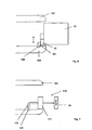
- the tool head 10 according to the invention has the considerable advantage that the three on the mounting plate. 91, 92, 93 mountable tools 161, 162, 163 during operation, ie the rotation of the tool head 10, are radially adjustable, such as Fig. 6 shows. This radial movement can be controlled during operation at any time.
- the tool head 10 according to the invention makes it possible, on the one hand, to provide inner and outer chamfers on the pipe end 150 and to machine the end face of the pipe end 150, but tube ends 150 of different diameters can be formed without changing the tools with the same chamfer length.
- radial undercuts 160 into the inner and outer walls of the pipe ends 150, as well as to introduce recesses into the inner and outer walls, in particular of a radial nature, which can have very different profiles.
- the supports 21, 22, 23 first moved inward, the tool head 10 then moved into the pipe end 150 and the supports 21, 22, 23 then moved radially outward until the cutting tools 161, 162, 163 touch the pipe wall , At this moment, the radial under-turn 160 is introduced into the wall of the pipe end 150.
- pipe ends 150 have an eccentricity, ie, the pipe wall changes slightly along the circumference.
- a piercing tool 170 for attaching an inner phase as well as for attaching a radial undercut 160 of constant depth along the circumference of the pipe end 150, a piercing tool 170 according to Fig. 7 intended.
- the piercing tool 170 has a roller 171, which is rotatable about an axis in the longitudinal direction L, which protrudes from one of the mounting plates 91, 92, 93 of the supports 21, 22, 23 on the side facing away from the support 21, 22, 23 Roller 171, a piercer 172 is provided, the tip of which projects radially beyond the roller 171.
- a radial background rotation 160 in a tube inner wall of the tool head 10 is first introduced with radially inwardly provided supports 21, 22, 23 in the interior of the pipe end 150 inside.
- the piercing tool 172 and the roller 171 do not come into contact with the pipe inner wall.
- the associated Sthubkeil 31, 32. 33 is moved back and the associated support 21, 22 23 moves by the force of the return spring 151, 152, 153 radially outward.
- the scraper 172 touches the tube inner wall and introduces a radial back turn 160 in the tube inner wall.
- the penetration depth of the piercing tool 172 is constantly limited by the diameter of the roller 171 along the circumference of the tube.
Landscapes
- Engineering & Computer Science (AREA)
- Mechanical Engineering (AREA)
- Turning (AREA)
- Cutting Tools, Boring Holders, And Turrets (AREA)
- Milling Processes (AREA)
- Drilling And Boring (AREA)
- Polyoxymethylene Polymers And Polymers With Carbon-To-Carbon Bonds (AREA)
Abstract
Description
Die Erfindung betrifft einen Werkzeugkopf, eine Maschine zur Bearbeitung der Enden eines stangenförmigen Profilmaterials, sowie ein Verfahren zur Bearbeitung der Enden eines stangenförmigen Profilmaterials.The invention relates to a tool head, a machine for processing the ends of a bar-shaped profile material, and a method for processing the ends of a bar-shaped profile material.
Rohrschneidemaschinen und für sie bestimmte Werkzeugköpfe sind im Stand der Technik bekannt. Herkömmliche Rohrschneidemaschinen weisen einen Werkzeugkopf mit einer oder mehreren Schneiden auf und eine Spannvorrichtung für ein zu bearbeitendes Rohr, das in Längsrichtung direkt vor dem rotierbaren Werkzeug gegenüber der Maschine positionsfest angeordnet wird. Der Werkzeugkopf wird in Rotationsbewegung gesetzt und in Längsrichtung gegen die Stirnfläche des Rohres verfahren. Durch entsprechende Anordnung der Schneiden können damit Innen- und Außenfasen an die Rohrwandung angebracht werden, sowie die Stirnfläche des Rohres bearbeitet werden.Pipe cutting machines and tool heads intended for them are known in the art. Conventional pipe cutting machines have a tool head with one or more cutting edges and a clamping device for a pipe to be machined, which is arranged positionally fixed in the longitudinal direction directly in front of the rotatable tool relative to the machine. The tool head is set in rotation and moved in the longitudinal direction against the end face of the tube. By appropriate arrangement of the cutting so that inner and outer bevels can be attached to the pipe wall, and the end face of the pipe to be edited.
Aus der
Nachteilig an dem beschriebenen Werkzeughalter ist dessen nicht zufriedenstellende Präzision.A disadvantage of the tool holder described is its unsatisfactory precision.
Nachteilig an den beschriebenen Rohrschneidernaschinen ist die Tatsache, dass die Schneidwerkzeuge nicht steuerbar in radialer Richtung verfahrbar sind. Somit ist es insbesondere nicht möglich, Nuten, Aussparungen und Ähnliches hinter der Stirnfläche in die Rohrinnen- oder Rohraußenwandung einzubringen.A disadvantage of the described pipe cutting machines is the fact that the cutting tools are not controllable movable in the radial direction. Thus, it is particularly not possible to introduce grooves, recesses and the like behind the end face in the pipe inside or pipe outer wall.
Es ist Aufgabe der vorliegenden Erfindung, einen eingangs genannten Werkzeugkopf, eine eingangs genannte Maschine und ein Verfahren zur Bearbeitung von Enden eines stangenförmigen Profilmaterials zur Verfügung zu stellen.It is an object of the present invention to provide a tool head mentioned above, an aforementioned machine and a method for processing ends of a rod-shaped profile material available.
Hinsichtlich des Werkzeugkopfes wird die genannte Aufgabe mit einem Werkzeugkopf mit Merkmalen des Anspruchs 1 erfüllt.With regard to the tool head, the stated object is achieved with a tool head having features of claim 1.
Unter Hinterdrehungen werden hier insbesondere radial um das stangenförmige Profilmaterial innen- oder/oder außenwandig umlaufende Nuten, Aussparungen, Konturenu. ä. verstanden. Diese Aussparungen, Nuten können entlang des radialen Umfanges Veränderungen aufweisen, so können die Nuten entlang des Umfanges eine veränderliche Tiefe, Breite oder ein in einem Querschnitt entlang der Längsrichtung unterschiedliches Profil aufweisen. Hinterdrehungen können von der Stimfläche des Profilmaterials an jeder Stelle beabstandet sein, dazu wird Material von der entsprechenden Materialwandung innen- oder außenseitig abgetragen, ohne dass dabei aber Profilmaterial zwischen der Stirnseite und dem abzutragenden Bereich entfernt wird. Insbesondere können radial umlaufende Nuten, die um einen bestimmten Abstand von der Stimfläche des Materials beabstandet sind, in die Materialinnen- und /oder Außenwandung eingebracht werden.Undercuts here in particular radially around the rod-shaped profile material inside or outside or circumferential grooves, recesses, Konturenu. Ä. understood. These recesses, grooves may have variations along the radial circumference, so the grooves along the circumference of a variable depth, width or have a different profile in a cross section along the longitudinal direction profile. Back-turns can be spaced from the end face of the profile material at any point, this is material of the corresponding material wall inside or outside removed, but without that profile material between the front and the area to be removed is removed. In particular, radially encircling grooves, which are spaced apart from the end face of the material by a certain distance, can be introduced into the material inner and / or outer wall.
Der erfindungsgemäße Werkzeugkopf weist dazu ein Gehäuse auf, in dem wenigstens ein Schubkeil vorgesehen ist, der in einer ersten Zahnführung in Längsrichtung hin und her beweglich angeordnet ist. Die erste Zahnführung weist zwei miteinander korrespondierende und ineinander in Längsrichtung hin und her gleitende Zahnprofile auf. Ein erstes Zahnprofil ist auf eine Außenwandung des Schubkeils aufgebracht, während ein korrespondierendes erstes Zahnprofil auf einer Innenwandung der zugeordneten Schubkeilsführung in einem Gehäuse vorgesehen ist. Die Zahnführung erzeugt eine vergrößerte Kontaktfläche zwischen Schubkeil und Gehäuse. Somit entsteht gegenüber einer glatten T-Führung oder Schwalbenschwanz-Führung eine deutlich verbesserte Führung, deutlich erhöhter Güte, verbesserter Wiederholgenauigkeit und Präzision.For this purpose, the tool head according to the invention has a housing in which at least one thrust wedge is provided, which is arranged to be movable back and forth in the longitudinal direction in a first toothed guide. The first toothed guide has two tooth profiles which correspond with one another and slide back and forth in the longitudinal direction. A first tooth profile is applied to an outer wall of the thrust wedge, while a corresponding first tooth profile is provided on an inner wall of the associated thrust wedge guide in a housing. The tooth guide generates an enlarged contact surface between the thrust wedge and the housing. Thus, compared to a smooth T-guide or dovetail guide results in a significantly improved leadership, significantly increased quality, improved repeatability and precision.
Jedem der Schubkeile ist ein in jeweils einer zweiten Zahnführung ein in einer quer zur Längsrichtung angeordneten Richtung beweglicher Support im Gehäuse zugeordnet. Hinsichtlich der zweiten Zahnführung des Supports gilt sinngemäß das Gleiche wie bei der ersten Zahnführung des Schubkeils. Das außenwandig am Support angebrachte zweite Zahnprofil wirkt mit einem in einer im Gehäuse eingelassenen Schubkeilführung innenwandig aufgebrachten korrespondierenden zweiten Zahnprofil zusammen. Aufgrund der Vergrößerung der Kontaktfläche entsteht auch hier eine Zahnführung mit hoher Güte. Der Schubkeil und der zugeordnete Support stehen über eine schräge Kontaktfläche miteinander gleitend in Berührung und eine Bewegung des Schubkeils in Längsrichtung wird über die schräge Kontaktfläche in eine Querbewegung des zugeordneten Supports umgewandelt. Die schräge Kontaktfläche ist vorzugsweise über ihre gesamte Ausdehnung glatt und mit gleich bleibender Steigung ausgeformt.Each of the thrust wedges is associated in each case with a second tooth guide in a direction transverse to the longitudinal direction arranged movable support in the housing. With regard to the second tooth guide of the support, the same applies mutatis mutandis to the first tooth guide of the thrust wedge. The externally mounted on the support second tooth profile cooperates with a recessed in a wedge guide inserted inside wall corresponding second tooth profile. Due to the enlargement of the contact surface, a tooth guide with high quality is also produced here. The thrust wedge and the associated support are slidably in contact with each other via an inclined contact surface, and longitudinal movement of the thrust wedge is converted via the inclined contact surface into transverse movement of the associated support. The oblique contact surface is preferably smooth over its entire extent and formed with a constant pitch.
Zur weiteren Erhöhung der Führungsgenauigkeit und Güte der zweiten Zahnführung weist der Support einen in Querrichtung verlaufenden Supportarm auf. Vorzugsweise verläuft die Querrichtung senkrecht zur Längsrichtung und in radialer Richtung des Schneidwerkzeugs.To further increase the guiding accuracy and quality of the second tooth guide, the support has a transversely extending support arm. Preferably, the transverse direction is perpendicular to the longitudinal direction and in the radial direction of the cutting tool.
Am Support ist ein Schneidwerkzeug, vorzugsweise an einer Befestigungsplatte, befestigbar. Vorteilhafterweise ist das am Support befestigte Schneidwerkzeug so in radialer Richtung beweglich.On the support is a cutting tool, preferably on a mounting plate fastened. Advantageously, the cutting tool attached to the support is movable in the radial direction.
Während des Betriebs ist der Werkzeugkopf in schneller Rotationsbewegung um die Längsachse. Der erfindungsgemäße Werkzeugkopf ermöglicht es, die Schneidwerkzeuge auch während der Rotationsbewegung radial gesteuert zu verstellen. Dazu ist der Werkzeugkopf auf eine Drehdurchführung montiert, die drei nebeneinander in Längsrichtung angeordnete Schiebestangen aufweist. Die Enden der Schiebestangen können die Schubkeile berühren und eine Wirkverbindung mit ihnen ausbilden. Vorzugsweise wird eine Schubkraft durch die Schubstange auf den zugeordneten Schubkeil übertragen.During operation, the tool head is in rapid rotational motion about the longitudinal axis. The tool head according to the invention makes it possible to adjust the cutting tools radially controlled during the rotational movement. For this purpose, the tool head is mounted on a rotary feedthrough, which has three juxtaposed longitudinally sliding rods. The ends of the push rods can contact the thrust keys and form an operative connection with them. Preferably, a thrust force is transmitted through the push rod to the associated thrust wedge.
Vorzugsweise ist dem wenigstens einen Schubkeil und dem wenigstens einen Support jeweils-eine Rückstellfeder zugeordnet Der Schubkeil ist durch Schubkraft auf einen aus dem Werkzeugkopf entgegen der Längsrichtung heraus ragenden Schubkeilarm an einer Stirnseite des Werkzeugkopfes in den Werkzeugkopf hinein drückbar, während der gleiche Schubkeil durch die Rückstellfeder automatisch entgegen der Längsrichtung zurückgesetzt wird.Preferably, the at least one pusher and the at least one support each associated with a return spring The pusher is pushed by a thrust force on the tool head against the longitudinal direction outwardly projecting pusher arm on an end face of the tool head into the tool head, while the same pusher wedge by the return spring automatically reset against the longitudinal direction.
Durch die schräge Kontaktfläche wird die Längsbewegung des Schubkeils in eine Querbewegung des Supports umgelenkt. Durch Druck des Schubkeils wird der Support nach radial innen bewegt, während bei Entlastung der Schubkeil aufgrund der ihm zugeordneten Rückstellfeder nach radial außen bewegt wird. Durch gesteuerte Schubkraft auf den Schubkeilarm ist eine entsprechend gesteuerte Querbewegung des zugehörigen Schneidwerkzeugs möglich.Due to the inclined contact surface, the longitudinal movement of the thrust wedge is deflected into a transverse movement of the support. By pressing the thrust wedge of the support is moved radially inward, while relieving the thrust wedge is moved radially outward due to the associated return spring. By controlled thrust on the thrust wedge arm a correspondingly controlled transverse movement of the associated cutting tool is possible.
Das Schneidwerkzeug ermöglicht es, beispielsweise radiale Hinterdrehungen auf eine Außenwandung eines stangenförmigen, im Querschnitt kreisförmigen Profilmaterials einzubringen. Dazu werden die Schneidwerkzeuge zunächst radial nach außen verfahren, der Werkzeugkopf in Rotationsbewegung gesetzt und dann in Längsrichtung zur Stirnfläche des stangenförmigen Profilmaterials hin verfahren, so weit, dass die Schneidwerkzeuge das Ende des stangenförmigen Profilmaterials hinterlaufen. Erst jetzt wird durch gesteuerte Druckkraft auf den wenigstens einen Schubkeilarm das Schneidwerkzeug gesteuert nach innen verfahren und damit eine von der Stirnfläche des Profilmaterials beabstandete Hinterdrehung in die Außenwandung eingebracht.The cutting tool makes it possible, for example, to introduce radial undercuts on an outer wall of a rod-shaped, circular cross-section profile material. For this purpose, the cutting tools are first moved radially outward, set the tool head in rotation and then moved in the longitudinal direction to the end face of the rod-shaped profile material, so far that the cutting tools behind the end of the bar-shaped profile material. Only now, the cutting tool controlled by inward pressure on the at least one thrust wedge arm moved inward and thus a Inserted from the end face of the profile material rear rotation in the outer wall.
Darüber hinaus ist es möglich, radiale Hinterdrehungen in eine Innenwandung eines kreisförmigen Materialendes einzubringen, indem die Schneidwerkzeuge zunächst radial nach innen verfahren werden, dann durch Längsverfahren des Werkzeugkopfes in das Innere des Materials eingeführt werden und in Rotationsbewegung gesetzt werden. Erst jetzt werden die Schneidwerkzeuge durch Entlasten der Schubkeilarme nach radial außen bewegt und ermöglichen es damit, eine radiale Hinterdrehung innenwandig in das Material einzubringen.In addition, it is possible to introduce radial undercuts in an inner wall of a circular material end by the cutting tools are first moved radially inward, then be introduced by longitudinal process of the tool head in the interior of the material and set in rotational motion. Only now, the cutting tools are moved by relieving the Schubkeilarme radially outward and thus make it possible to introduce a radially inward rotation inside the wall in the material.
In einer besonders bevorzugten Ausführungsform der Erfindung ist eine Mehrzahl von Supports in einem Querschnitt senkrecht zur Längsrichtung sternförmig vorgesehen und jeder Support weist einen ihm zugeordneten quer verlaufenden Supportarm auf. Dabei sind die Supportarme in einer Ansicht in Längsrichtung sich kreuzend angeordnet. Diese Ausführungsform der Erfindung ermöglicht es, auf Platz sparende Weise und trotzdem bei hoher Führungsgenauigkeit eine Mehrzahl, vorzugsweise genau drei Supporte, in dem Werkzeugkopf unterzubringen. Durch die gekreuzte Anordnung der Supportarme, die vorzugsweise entlang ihrer Außenfläche auch mit einem korrespondierenden zweiten Zahnprofil entlang ihrer Querbewegungsrichtung versehen sind, behält der Support eine hohe Führungsgüte und Wiederholgenauigkeit.In a particularly preferred embodiment of the invention, a plurality of supports are provided star-shaped in a cross section perpendicular to the longitudinal direction and each support has a transverse support arm associated therewith. The support arms are arranged crossing each other in a longitudinal direction. This embodiment of the invention makes it possible to accommodate a plurality of, preferably exactly three, supports in a space-saving manner and nevertheless with high guidance accuracy in the tool head. By the crossed arrangement of the support arms, which are preferably provided along its outer surface with a corresponding second tooth profile along its transverse direction of movement, the support retains a high quality of leadership and repeatability.
Günstigerweise ist das Gehäuse in einem Querschnitt senkrecht zur Längsrichtung im Wesentlichen kreisförmig ausgebildet, und der wenigstens eine Schubkeil weist an sich einander am Schubkeil gegenüberliegenden, radial verlaufenden Außenwandungen ein erstes äußeres Zahnprofil auf, das mit einem ersten inneren Zahnprofil an einer Innenwandung der Schubkeilführung als erste Zahnführung zusammenwirkt.Conveniently, the housing is formed in a cross-section perpendicular to the longitudinal direction substantially circular, and the at least one pusher has at each other on the pusher wedge opposite, radially extending outer walls on a first outer tooth profile, with a first inner tooth profile on an inner wall of the pusher guide as the first Tooth guide cooperates.
Günstigenfalls sind genau die radialen Außenwandungen eines im Querschnitt senkrecht zur Längsrichtung rechteckigen Schubkeils mit einem in Längsrichtung verlaufenden ersten äußeren Zahnprofil versehen. Das korrespondierend erste innere Zahnprofil ist auf die Innenwandung der Schubkeilfführung im Gehäuse aufgebracht.Conveniently, exactly the radial outer walls of a rectangular in cross section to the longitudinal direction of the thrust wedge are provided with a longitudinally extending first outer tooth profile. The corresponding first inner tooth profile is applied to the inner wall of the thrust wedge guide in the housing.
Alle Zahnprofile werden in besonders exakter Weise durch Drahterodieren hergestellt. Das Drahterodieren macht es notwendig, dass sich die Zahnprofile über die gesamte Ausdehnung der zugeordneten Führungen des Bauteils erstrecken.All tooth profiles are manufactured in a particularly exact manner by wire EDM. Wire eroding requires that the tooth profiles extend over the entire extent of the associated guides of the component.
In einer weiteren bevorzugten Ausführungsform der Erfindung weist der wenigstens eine Support an einander gegenüberliegenden radial verlaufenden Wandungen jeweils ein zweites äußeres Zahnprofil auf, das mit einem zweiten inneren Zahnprofil an einer Innenwandung der Supportführung zur zweiten Zahnführung zusammenwirkt. Die zweite Zahnführung ist vorzugsweise senkrecht zur Längsrichtung radial durch das Gehäuse hindurch geführt. Das äußere zweite Zahnprofil erstreckt sich günstigerweise über die gesamte radiale Ausdehnung des Supportarmes. Durch die zusätzlich zweite Zahnführung des Supportes wird eine besonders hohe Führungsgenauigkeit und -güte erreicht.In a further preferred embodiment of the invention, the at least one support on opposite radially extending walls each have a second outer tooth profile, which cooperates with a second inner tooth profile on an inner wall of the support guide to the second tooth guide. The second tooth guide is preferably guided radially through the housing perpendicular to the longitudinal direction. The outer second tooth profile conveniently extends over the entire radial extent of the support arm. Due to the additional second toothing of the support a particularly high guidance accuracy and quality is achieved.
Vorzugsweise weist der wenigstens eine Schubkeil eine konstante Bauhöhe auf. Unter Bauhöhe wird hier die Ausdehnung des Schubkeils senkrecht zur Längsrichtung und senkrecht zum Radius des Werkzeugkopfes verstanden. Zur Kostenersparnis sind die Schubkeile baugleich.Preferably, the at least one pusher has a constant height. Under construction height is understood here as the extent of the thrust wedge perpendicular to the longitudinal direction and perpendicular to the radius of the tool head. To save costs, the sliding wedges are identical.
In einer weiteren günstigen Ausführungsform der Erfindung weist der im Gehäuse vorgesehene Teil des wenigstens einen Supports ebenfalls eine konstante Bauhöhen entlang seiner gesamten Ausdehnung auf.In a further favorable embodiment of the invention, the part of the at least one support provided in the housing likewise has a constant overall height along its entire extent.
Vorteilhafterweise ragt der Schubkeil während des Betriebs zeitweise in die Supportführung hinein. Dazu ist die Bauhöhe des Schubkeils um die Zahntiefe des zweiten Zahnprofils kleiner als die Bauhöhe des Supports.Advantageously, the thrust wedge temporarily projects into the support guide during operation. For this purpose, the height of the thrust wedge to the tooth depth of the second tooth profile is smaller than the height of the support.
Support und Schubkeil sind in einer kostengünstigen Ausführungsform der Erfindung durch entsprechend dimensionierte Rückstellfedern automatisch rückstellbar.Support and pusher are automatically recoverable in a cost-effective embodiment of the invention by appropriately sized return springs.
Hinsichtlich der Maschine zur Bearbeitung der Enden eines stangenförmigen Profilmaterials wird die gestellte Aufgabe durch eine Maschine mit einen oben beschriebenen Werkzeugkopf gelöst Eine Maschine, die eine entsprechende Steuerung des Werkzeugkopfes ermöglicht, weist beispielsweise eine Drehdurchführung auf.With regard to the machine for machining the ends of a bar-shaped profile material, the stated object is achieved by a machine having a tool head described above. A machine which enables a corresponding control of the tool head has, for example, a rotary feedthrough.
Hinsichtlich des Verfahrens wird die Aufgabe durch ein Verfahren zur Bearbeitung von Enden eines stangenförmigen Profilmaterials gelöst, indem eine radiale Hinterdrehung in eine Wandung des Profilmaterials eingebracht wird. Ein derartiges Verfahren ist durch einen oben beschriebenen Werkzeugkopf und eine oben beschriebenen Maschine ausführbar.With regard to the method, the object is achieved by a method for machining ends of a bar-shaped profile material by introducing a radial undercut into a wall of the profile material. Such a method can be carried out by a tool head described above and a machine described above.
Vorzugsweise wird der wenigstens eine Support zur Bearbeitung einer Profilmaterialaußenwandung zunächst nach radial außen oder zur Bearbeitung einer Profilamterialinnenwandung zunächst nach radial innen verfahren. Dadurch ist es möglich, das Schneidwerkzeug in Längsrichtung des Profilmaterial berührungsfrei hinter eine Stimfläche des Profilmaterial zu führen, das Schneidwerkzeug dann relativ zum Profilmaterial um eine in Längsrichtung ausgerichtete Längsachse zu rotieren und das Schneidwerkzeug während der Rotation radial zur Wandung hin zu verstellen, bis die Wandung vom Schneidwerkzeug berührt wird und durch die Berührung eine Hinterdrehung in die Wandung einzubringen.Preferably, the at least one support for machining a profile material outer wall is first moved radially outward or initially to work radially inward for machining a profile inner wall. This makes it possible to guide the cutting tool in the longitudinal direction of the profile material without contact behind an end face of the profile material, then rotate the cutting tool relative to the profile material about a longitudinal axis aligned longitudinally and adjust the cutting tool radially during rotation to the wall until the wall is touched by the cutting tool and bring by the touch of a back turn in the wall.
Die Erfindung wird anhand eines Ausführungsbeispieles in sieben Figuren beispielhaft beschrieben. Dabei zeigen:
- Fig. 1
- eine perspektivische Ansicht des erfindungsgemäßen Werkzeugkopfes,
- Fig. 2
- eine zweite perspektivische Ansicht des erfindungsgemäßen Werkzeugkopfes,
- Fig. 3
- eine Ansicht gemäß
Fig. 1 mit abgenommenem Gehäuse, - Fig. 5
- eine prinzipielle Ansicht des Werkzeugkopfes ohne Gehäuse,
- Fig. 4
- eine Ansicht gemäß
Fig. 3 mit Halteplatten, - Fig. 6
- einen Werkzeugkopf mit Schneide,
- Fig. 7
- einen Werkzeugkopf mit erfindungsgemäßem Stechmeißel.
- Fig. 1
- a perspective view of the tool head according to the invention,
- Fig. 2
- a second perspective view of the tool head according to the invention,
- Fig. 3
- a view according to
Fig. 1 with removed housing, - Fig. 5
- a basic view of the tool head without housing,
- Fig. 4
- a view according to
Fig. 3 with holding plates, - Fig. 6
- a tool head with cutting edge,
- Fig. 7
- a tool head with inventive chisel.
Der in
Der in
Die in
Jeder der Schubkeile 31, 32, 33 weist zwei sich gegenüberliegende in radialer Richtung verlaufenden Außenwandungen auf, die jeweils vollständig mit einem in Längsrichtung verlaufenden Zahnprofil 81, 82, 83 versehen sind. Das Zahnprofil 81, 82, 83 wird mittels eines Drahterodierverfahrens in die Außenwandungen eingebracht. Die senkrecht zur Längsachse L und senkrecht zur Radialrichtung vorgesehene Bauhöhe jeder der Schubkeile 31, 32, 33 ist über die gesamte Längs- und Radialausdehnung des Schubkeiles 31, 33, 33 konstant. Die schräge Kontaktfläche 71, 72, 73 des Schubkeils 31, 32, 33 weist eine konstante Steigung über ihre gesamte Ausdehnung auf. Sie ist in ständigem und gleitendem Kontakt mit einer korrespondierenden schrägen Kontaktfläche 71. 72. 73 des dem Schubkeil 31, 32. 33 zugeordneten Supports 21, 22, 23.Each of the
Jeder Support 21, 22, 23 weist gemäß
Die senkrecht zur Längsachse L und senkrecht zur Radialrichtung angeordnete Bauhöhe jedes Supports 21, 22, 23 im Gehäuse 11 ist im Wesentlichen über die gesamte Ausdehnung des Supports 21, 22, 23 im Gehäuse 11 konstant.The height of each
Die Bauhöhe der Schubkeile 31, 32, 33 ist in Längsrichtung und Radialrichtung überall gleich. An jedem Schubkeil 31, 32, 33 liegen sich erste Zahnprofile 81, 82, 83 gegenüber. Die Bauhöhe der Schubkeile 31, 32, 33 ist um die Zahnprofiltiefe der zweiten Zahnprofile 111, 112, 113 kleiner als die Bauhöhe der Supports 21, 22, 23.The overall height of the
Die Zahnprofile 81, 82, 83, 111, 112, 113 korrespondieren mit zugeordneten, in das Innere des Gehäuses 11 eingelassenen Zahnprofilen.The tooth profiles 81, 82, 83, 111, 112, 113 correspond with associated, embedded in the interior of the
Das Gehäuse 11 wird aus einem kurzen Vollprofilrohr hergestellt. Die zur Aufnahme der Schubkeile vorgesehenen drei Schubkeilführungen sind in einem Querschnitt senkrecht zur Längsachse L rechteckig ausgebildet, und sie erstrecken sich über die gesamte Länge des Werkzeugkopfes 10 und weisen an ihren radial verlaufenden Innenwandungen ein sich über die gesamte Längsausdehnung erstreckendes korrespondierendes erstes Zahnprofil auf.The
Das korrespondierende erste Zahnprofil wird ebenfalls durch Drahterodieren hergestellt.The corresponding first tooth profile is also produced by wire eroding.
Das Gehäuse 11 weist darüber hinaus drei radiale Supportführungen für die drei Supports 21, 22, 23 auf. Die drei Supportführungen sind in radialer Richtung R1, R2, R3 vollständig durch das Gehäuse 11 geführt und weisen an ihren in radialer Richtung verlaufenden Innenwandungen ebenfalls durch Drahterodieren herstellbare zweite Zahnprofile auf. Die Breite der Supportführung ist etwas größer als die Breite der Schubkeilführung, so dass der in Längsrichtung L bewegliche Schubkeil 31, 32, 33 während des Betriebs ein Stück weit in die Führung des Supports 21, 22, 23 eindringen kann.The
Die drei Supportführungen sind an ihren zylindrischen Außenseiten mit jeweils zwei Verschlussplatten 121, 122, 123, 131, 132, 133 abgedeckt wie
Die Anordnung der Verschlussplatten 121, 122, 123, 131, 132, 133 ist in
Die Schubkeile 31, 32, 33 sind baugleich, während die Supports 21, 22, 23 nicht baugleich ausgebildet sind. Die Ausdehnung der Supports in Längsrichtung L ist gleich. Die radiale Ausdehnung der Supports ist ebenfalls gleich. Jedoch ist die Anordnung der Supportarme 101, 102, 103 relativ zum Support 21, 22, 23 verschieden. Die Supportarme 101, 102, 103 sind in Längsrichtung L versetzt am zugehörigen Support 21, 22, 23 angeordnet und zwar um die Längsausdehnung eines benachbarten Supportarmes 101, 102, 103, so dass die Supportarme 101, 102, 103 sich kreuzend im Gehäuse 11 angeordnet sind und sich ihre Radialbewegungen nicht gegenseitig stören. Dabei bilden die Befestigungsplatten 91, 92, 93 der Supports 21, 22, 23 eine gemeinsame ebene Fläche aus.The
Gegenüber dem bekannten Stand der Technik weist der erfindungsgemäße Werkzeugkopf 10 den erheblichen Vorteil auf, dass die drei auf der Befestigungsplatte. 91, 92, 93 montierbaren Werkzeuge 161, 162, 163 während des Betriebs, d. h. der Rotation des Werkzeugkopfes 10, radial verstellbar sind, wie
Üblicherweise weisen Rohrenden 150 eine Exzentrizität auf, d. h. dass die Rohrwandung sich entlang des Umfangs geringfügig ändert. Zur Anbringung einer Innenphase als auch zur Anbringung einer radialen Hinterdrehung 160 konstanter Tiefe entlang des Umfanges des Rohrendes 150 ist ein Stechmeißelwerkzeug 170 gemäß
Darüber hinaus ist es möglich, mit einem weiteren Werkzeug, das eine Rolle 171 und eine zwischen Rolle 171 und dem Support 21, 22, 23 angeordnete Schneide aufweist in entsprechender Weise, eine Fase entlang des Umfanges des Rohrendes 150 gleicher Länge an der Rahrinnenwandung anzubringen.Moreover, it is possible, with a further tool having a
- 1010
- Werkzeugkopftool head
- 1111
- Gehäusecasing
- 1616
- Bohrungdrilling
- 1717
- Bohrungdrilling
- 1818
- Bohrungdrilling
- 2121
- SupportSupport
- 2222
- SupportSupport
- 2323
- SupportSupport
- 3131
- Schubkeilthrust wedge
- 3232
- Schubkeilthrust wedge
- 3333
- Schubkeilthrust wedge
- 4141
- SchubkeilarmSchubkeilarm
- 4242
- SchubkeilarmSchubkeilarm
- 4343
- SchubkeilarmSchubkeilarm
- 5151
- Kontaktflächecontact area
- 5252
- Kontaktflächecontact area
- 5353
- Kontaktflächecontact area
- 6161
- RückstellfederReturn spring
- 6262
- RückstellfederReturn spring
- 6363
- RückstellfederReturn spring
- 7171
- Kontaktflächecontact area
- 7272
- Kontaktflächecontact area
- 7373
- Kontaktflächecontact area
- 8181
- Zahnprofiltooth profile
- 8282
- Zahnprofiltooth profile
- 8383
- Zahnprofiltooth profile
- 9191
- Befestigungsplattemounting plate
- 9292
- Befestigungsplattemounting plate
- 9393
- Befestigungsplattemounting plate
- 101101
- Supportarmsupport arm
- 102102
- Supportarmsupport arm
- 103103
- Supportarmsupport arm
- 111111
- Zahnprofiltooth profile
- 112112
- Zahnprofiltooth profile
- 113113
- Zahnprofiltooth profile
- 121121
- Verschlussplatteclosing plate
- 122122
- Verschlussplatteclosing plate
- 123123
- Verschlussplatteclosing plate
- 131131
- Verschlussplatteclosing plate
- 132132
- Verschlussplatteclosing plate
- 133133
- Verschlussplatteclosing plate
- 150150
- Rohrendepipe end
- 151151
- RückstellfederReturn spring
- 152152
- RückstellfederReturn spring
- 153153
- RückstellfederReturn spring
- 160160
- Hinterdrehungundercut
- 161161
- Schneidwerkzeugcutting tool
- 162162
- Schneidwerkzeugcutting tool
- 163163
- Schneidwerkzeugcutting tool
- 170170
- StechmeißelwerkzeugBench chisel tool
- 171171
- Rollerole
- 172172
- Stechmeißelbench chisel
- LL
- Längsrichtunglongitudinal direction
- R1R1
- Radialrichtungradial direction
- R2R2
- Radialrichtungradial direction
- R3R3
- Radialrichtungradial direction
Claims (15)
- Tool head with
a housing (11), in which
at least one thrusting wedge (31, 32, 33) is provided, able to move back and forth in the longitudinal direction (L) in a first guide, which
is coordinated with a support (21, 22, 23) in the housing (11), able to move in a second guide in a transverse direction (R1, R2, R3) transversely to the longitudinal direction.(L), and the thrusting wedge (31, 32, 33) and the support (21, 22, 23) are in sliding contact with each other via a slanted contact surface (51, 52, 53) and a movement of the thrusting wedge (31, 32, 33) in the longitudinal direction (L) brings about a transverse movement of the coordinated support (21, 22, 23) via the slanted contact surface (51, 52, 53) and
a cutting tool (161, 162, 163) can be fastened on the support (21, 22, 23), characterized in that the first and the second guide, each of them is a tooth guide and the support (21, 22, 23) has a support arm (101, 102, 103) extending in the transverse direction (R1, R2, R3). - Tool head per claim 1,
characterized in that
the housing (11) is fashioned essentially in circular shape in one cross section and a plurality of supports (21, 22, 23) is provided in the shape of a star in one cross section perpendicular to the lengthwise direction (L) and the support arms (101, 102, 103) are arranged in crossing manner, looking at them in the lengthwise direction (L). - Tool head per claim 2,
characterized in that
precisely three supports (21, 22, 23) are provided. - Tool head per claim 1,
characterized in that
the at least one thrusting wedge (31, 32, 33) has a first outer tooth profile (81, 82, 83) on opposite, radially extending outer walls, interacting with a first inner tooth profile on an inner wall of a thrusting wedge guide of the housing (11) of the first toothed guide. - Tool head per claim 1,
characterized in that
the at least one support (21, 22, 23) has a second outer tooth profile (111, 112, 113) on opposite, radially extending walls, interacting with a second inner tooth profile on an inner wall of a support guide of the housing (11). - Tool head according to at least one of the claims 2 - 5,
characterized in that
the thrusting wedges (31, 32, 33) are identical in construction. - Tool head according to at least one of the preceding claims,
characterized in that
the part of the at least one support (21, 22, 23) provided in the housing (11) has a constant design height. - Tool head per claim 1,
characterized in that
the design height of the thrusting wedge (31, 32, 33) is less than the design height of the corresponding support (21, 22, 23) by the depth of the second tooth profile (111, 112, 113). - Tool head according to at least one of the preceding claims,
characterized in that
the at least one thrusting wedge (31, 32, 33) and/or the at least one support (21, 22, 23) are each coordinated with a return spring (61, 62, 63, 151, 152, 153). - Tool head according to at least one of the preceding claims,
characterized in that
a necking tool (170) is provided on one support (21, 22, 23) with a roller (171) which can turn about an axis arranged in a lengthwise direction and a bench chisel (172) is arranged on the roller (171) at the side away from the support (21, 22, 23), whose tip projects radially beyond the diameter of the roller (171). - Machine for machining of the ends of a rodlike profile material with a tool head (10) according to at least one of the preceding claims.
- Machine per claim 11,
characterized in that
the tool head (10) is mounted on a rotary transmission leadthrough. - Method to be implemented on a machine according to claim 11 or 12, machining the ends of a rodlike profile material (150), in that a radial relief turning (160) is produced in one wall of the profile material (150).
- Method per claim 13,
characterized in that
the at least one support (21, 22, 23) for the machining of an outer wall of the profile material is at first moved radially outward or that for the machining of an inner wall of the profile material is at first moved radially inward. - Method per claim 13 or 14,
wherein a cutting tool (161, 162, 163) is led up in the lengthwise direction of the profile material (150) behind one end face of the profile material (150) without contacting it, the cutting tool (161, 162, 163) is rotated relative to the profile material (150) about a lengthwise axis oriented in the longitudinal direction and the cutting tool (161, 162, 163) is moved radially toward the wall during the rotation until the wall is contacted by the cutting tool (161, 162, 163), and a relief turning (160) is made in the wall by the contacting.
Applications Claiming Priority (2)
| Application Number | Priority Date | Filing Date | Title |
|---|---|---|---|
| DE102006055417A DE102006055417B4 (en) | 2006-11-22 | 2006-11-22 | Tool head for a pipe cutting machine |
| PCT/DE2007/002004 WO2008061494A1 (en) | 2006-11-22 | 2007-11-07 | Tool head for a pipe-cutting machine |
Publications (2)
| Publication Number | Publication Date |
|---|---|
| EP2106313A1 EP2106313A1 (en) | 2009-10-07 |
| EP2106313B1 true EP2106313B1 (en) | 2011-06-01 |
Family
ID=39083289
Family Applications (1)
| Application Number | Title | Priority Date | Filing Date |
|---|---|---|---|
| EP07846294A Active EP2106313B1 (en) | 2006-11-22 | 2007-11-07 | Tool head for a pipe-cutting machine |
Country Status (8)
| Country | Link |
|---|---|
| US (2) | US20100050831A1 (en) |
| EP (1) | EP2106313B1 (en) |
| JP (1) | JP5230639B2 (en) |
| AT (1) | ATE511421T1 (en) |
| CA (1) | CA2669569C (en) |
| DE (1) | DE102006055417B4 (en) |
| ES (1) | ES2365179T3 (en) |
| WO (1) | WO2008061494A1 (en) |
Cited By (2)
| Publication number | Priority date | Publication date | Assignee | Title |
|---|---|---|---|---|
| DE102015002483A1 (en) | 2015-02-27 | 2016-09-01 | Rattunde & Co. Gmbh | Method for reducing the regenerative rattle of cutting machines |
| DE102015118769A1 (en) | 2015-11-03 | 2017-05-04 | Rattunde & Co. Gmbh | Chamfering tool with guide for vibration elimination |
Families Citing this family (2)
| Publication number | Priority date | Publication date | Assignee | Title |
|---|---|---|---|---|
| DE102023104938A1 (en) | 2023-02-28 | 2024-08-29 | MAPAL Fabrik für Präzisionswerkzeuge Dr. Kress KG | Tool for machining a workpiece |
| CN118080907B (en) * | 2024-04-23 | 2024-08-02 | 艾瑞(成都)排放控制技术有限公司 | Mandrel positioning mechanism for cutting off spinning pipe orifice |
Family Cites Families (16)
| Publication number | Priority date | Publication date | Assignee | Title |
|---|---|---|---|---|
| DE344944C (en) * | 1918-02-05 | 1921-12-03 | Wilhelm Westerheide | Tool head for processing pipes and pipe sleeves, in particular for cutting conical internal threads on pipe turning jaws with lead screw drive |
| US2463292A (en) * | 1946-02-06 | 1949-03-01 | Hugh E Mccallion | Machine element |
| US2852969A (en) * | 1955-08-23 | 1958-09-23 | Int Harvester Co | Adjustable single blade chamfering tool |
| JPS52131289A (en) * | 1976-04-26 | 1977-11-04 | Daijietsuto Kougiyou Kk | Boring tool |
| CH627676A5 (en) * | 1978-05-11 | 1982-01-29 | Kaiser Heinz Ag | TWO CUTTER BORING HEAD. |
| CH660702A5 (en) * | 1983-09-20 | 1987-06-15 | Urma Werkzeug Maschf | BORING TOOL WITH A TWO-CUTTER HEAD. |
| US4685362A (en) * | 1985-06-19 | 1987-08-11 | Julius Mayer | Quick-mount thread cutting attachment for lathes |
| DE8606993U1 (en) * | 1986-03-14 | 1986-05-22 | Kotthaus & Busch, 5630 Remscheid | Milling cutter for cutting the inside of pipes |
| DE19951658A1 (en) * | 1999-10-27 | 2001-05-10 | Wohlhaupter Gmbh | Tool holder |
| DE29923695U1 (en) * | 1999-10-27 | 2001-02-22 | Wohlhaupter Gmbh, 72636 Frickenhausen | Tool holder |
| WO2003013769A2 (en) * | 2001-08-08 | 2003-02-20 | Johne + Co. Präzisionswerkzeuge Gmbh | Multiple cutting edge rotary tool |
| DE10151528B4 (en) * | 2001-10-18 | 2004-02-12 | Ds Technologie Werkzeugmaschinenbau Gmbh | Vertical lathe with an attachment head on a tool slide |
| FI117593B (en) * | 2002-06-28 | 2006-12-15 | Mandrel Oy | Arrangement for machining |
| DE102004004498A1 (en) * | 2004-01-29 | 2005-08-18 | Sms Meer Gmbh | Device for processing pipe ends, in particular for cutting threaded connections |
| DE102005043851A1 (en) * | 2005-09-13 | 2007-03-22 | Komet Group Holding Gmbh | Tool head with adjusting motor |
| US7537218B2 (en) * | 2006-07-24 | 2009-05-26 | Wachtler William R | Chuck jaw with adjustable tooth |
-
2006
- 2006-11-22 DE DE102006055417A patent/DE102006055417B4/en not_active Expired - Fee Related
-
2007
- 2007-11-07 JP JP2009537477A patent/JP5230639B2/en active Active
- 2007-11-07 EP EP07846294A patent/EP2106313B1/en active Active
- 2007-11-07 CA CA2669569A patent/CA2669569C/en active Active
- 2007-11-07 ES ES07846294T patent/ES2365179T3/en active Active
- 2007-11-07 WO PCT/DE2007/002004 patent/WO2008061494A1/en active Application Filing
- 2007-11-07 AT AT07846294T patent/ATE511421T1/en active
- 2007-11-07 US US12/312,688 patent/US20100050831A1/en not_active Abandoned
-
2011
- 2011-12-09 US US13/374,067 patent/US8424428B2/en active Active
Cited By (4)
| Publication number | Priority date | Publication date | Assignee | Title |
|---|---|---|---|---|
| DE102015002483A1 (en) | 2015-02-27 | 2016-09-01 | Rattunde & Co. Gmbh | Method for reducing the regenerative rattle of cutting machines |
| DE102015118769A1 (en) | 2015-11-03 | 2017-05-04 | Rattunde & Co. Gmbh | Chamfering tool with guide for vibration elimination |
| WO2017076833A1 (en) | 2015-11-03 | 2017-05-11 | Rattunde & Co Gmbh | Chamfering tool with guide for eliminating vibrations |
| US11045877B2 (en) | 2015-11-03 | 2021-06-29 | Rattunde Ag | Chamfering tool with guide for eliminating vibrations |
Also Published As
| Publication number | Publication date |
|---|---|
| DE102006055417B4 (en) | 2010-05-20 |
| US20100050831A1 (en) | 2010-03-04 |
| DE102006055417A1 (en) | 2008-06-05 |
| EP2106313A1 (en) | 2009-10-07 |
| US8424428B2 (en) | 2013-04-23 |
| ES2365179T3 (en) | 2011-09-23 |
| WO2008061494A1 (en) | 2008-05-29 |
| CA2669569C (en) | 2014-02-25 |
| CA2669569A1 (en) | 2008-05-29 |
| JP5230639B2 (en) | 2013-07-10 |
| JP2010510080A (en) | 2010-04-02 |
| US20120227553A1 (en) | 2012-09-13 |
| ATE511421T1 (en) | 2011-06-15 |
Similar Documents
| Publication | Publication Date | Title |
|---|---|---|
| EP3033202B1 (en) | Twin clamp and method for simultaneously clamping two elongate profile segments | |
| EP1896207B1 (en) | Tool system with interface | |
| DE102019004527A1 (en) | Device for clamping workpieces for machining centers | |
| EP2266732B1 (en) | Clamping system | |
| DE102017214165B4 (en) | Rotary tool as well as carrier and cutting insert for such | |
| EP2106313B1 (en) | Tool head for a pipe-cutting machine | |
| EP2001625A1 (en) | Clamping apparatus for rotating tools or workpieces | |
| DE2631666C3 (en) | Tool for the drawn boring of pipes | |
| DE102017110547B4 (en) | Method for clamping a component | |
| DE102014014932B4 (en) | Method for boring a pre-drilled workpiece core hole | |
| EP3081324A1 (en) | Long turning machine with two nc-controlled processing axes and method for machining workpieces on a long turning machine with two nc-controlled processing axes | |
| EP0798063B1 (en) | Boring tool | |
| DE102012104392A1 (en) | Tool holder for tool for deburring and chamfering of curved wall, has fixing portion that is movably supported in direction of rotation axis on coupling against force of spring relative to clamping portion along radial direction | |
| EP0563979B1 (en) | Coupling | |
| DE202013012454U1 (en) | Cutting tool, in particular boring bar | |
| EP3528984B1 (en) | Tool for machining boreholes | |
| DE2457505A1 (en) | DEEP HOLE DRILL HEAD | |
| EP2295177A1 (en) | Tool assembly and groove drawing machine for producing grooves or depressions | |
| EP3287215B1 (en) | Method for producing a groove structure in an internal surface of a piston | |
| DE19710730B4 (en) | Rolling process and two-roll profile rolling machine for producing pitch profiles with an odd number of turns on rotationally symmetrical workpieces | |
| EP1038618B1 (en) | Tool head for a lathe | |
| DE102016107244B4 (en) | Hydraulic expansion clamping device | |
| DE19500515B4 (en) | Tool head for pipe threading machines | |
| DE102004008167A1 (en) | Boring head for reamer has at least one adjustable angle cutting plate preferably two diametrically opposite cutting plates mounted on the end face of the tool | |
| DE3320068C2 (en) |
Legal Events
| Date | Code | Title | Description |
|---|---|---|---|
| PUAI | Public reference made under article 153(3) epc to a published international application that has entered the european phase |
Free format text: ORIGINAL CODE: 0009012 |
|
| 17P | Request for examination filed |
Effective date: 20090512 |
|
| AK | Designated contracting states |
Kind code of ref document: A1 Designated state(s): AT BE BG CH CY CZ DE DK EE ES FI FR GB GR HU IE IS IT LI LT LU LV MC MT NL PL PT RO SE SI SK TR |
|
| DAX | Request for extension of the european patent (deleted) | ||
| 17Q | First examination report despatched |
Effective date: 20100317 |
|
| GRAP | Despatch of communication of intention to grant a patent |
Free format text: ORIGINAL CODE: EPIDOSNIGR1 |
|
| GRAS | Grant fee paid |
Free format text: ORIGINAL CODE: EPIDOSNIGR3 |
|
| GRAA | (expected) grant |
Free format text: ORIGINAL CODE: 0009210 |
|
| AK | Designated contracting states |
Kind code of ref document: B1 Designated state(s): AT BE BG CH CY CZ DE DK EE ES FI FR GB GR HU IE IS IT LI LT LU LV MC MT NL PL PT RO SE SI SK TR |
|
| REG | Reference to a national code |
Ref country code: GB Ref legal event code: FG4D Free format text: NOT ENGLISH |
|
| REG | Reference to a national code |
Ref country code: CH Ref legal event code: EP |
|
| REG | Reference to a national code |
Ref country code: IE Ref legal event code: FG4D Free format text: LANGUAGE OF EP DOCUMENT: GERMAN |
|
| REG | Reference to a national code |
Ref country code: DE Ref legal event code: R096 Ref document number: 502007007353 Country of ref document: DE Effective date: 20110714 |
|
| REG | Reference to a national code |
Ref country code: NL Ref legal event code: T3 |
|
| REG | Reference to a national code |
Ref country code: CH Ref legal event code: NV Representative=s name: R. A. EGLI & CO. PATENTANWAELTE |
|
| REG | Reference to a national code |
Ref country code: ES Ref legal event code: FG2A Ref document number: 2365179 Country of ref document: ES Kind code of ref document: T3 Effective date: 20110923 |
|
| PG25 | Lapsed in a contracting state [announced via postgrant information from national office to epo] |
Ref country code: SE Free format text: LAPSE BECAUSE OF FAILURE TO SUBMIT A TRANSLATION OF THE DESCRIPTION OR TO PAY THE FEE WITHIN THE PRESCRIBED TIME-LIMIT Effective date: 20110601 Ref country code: LT Free format text: LAPSE BECAUSE OF FAILURE TO SUBMIT A TRANSLATION OF THE DESCRIPTION OR TO PAY THE FEE WITHIN THE PRESCRIBED TIME-LIMIT Effective date: 20110601 |
|
| PG25 | Lapsed in a contracting state [announced via postgrant information from national office to epo] |
Ref country code: SI Free format text: LAPSE BECAUSE OF FAILURE TO SUBMIT A TRANSLATION OF THE DESCRIPTION OR TO PAY THE FEE WITHIN THE PRESCRIBED TIME-LIMIT Effective date: 20110601 Ref country code: FI Free format text: LAPSE BECAUSE OF FAILURE TO SUBMIT A TRANSLATION OF THE DESCRIPTION OR TO PAY THE FEE WITHIN THE PRESCRIBED TIME-LIMIT Effective date: 20110601 Ref country code: CY Free format text: LAPSE BECAUSE OF FAILURE TO SUBMIT A TRANSLATION OF THE DESCRIPTION OR TO PAY THE FEE WITHIN THE PRESCRIBED TIME-LIMIT Effective date: 20110601 Ref country code: GR Free format text: LAPSE BECAUSE OF FAILURE TO SUBMIT A TRANSLATION OF THE DESCRIPTION OR TO PAY THE FEE WITHIN THE PRESCRIBED TIME-LIMIT Effective date: 20110902 Ref country code: LV Free format text: LAPSE BECAUSE OF FAILURE TO SUBMIT A TRANSLATION OF THE DESCRIPTION OR TO PAY THE FEE WITHIN THE PRESCRIBED TIME-LIMIT Effective date: 20110601 |
|
| REG | Reference to a national code |
Ref country code: IE Ref legal event code: FD4D |
|
| PG25 | Lapsed in a contracting state [announced via postgrant information from national office to epo] |
Ref country code: IE Free format text: LAPSE BECAUSE OF FAILURE TO SUBMIT A TRANSLATION OF THE DESCRIPTION OR TO PAY THE FEE WITHIN THE PRESCRIBED TIME-LIMIT Effective date: 20110601 Ref country code: EE Free format text: LAPSE BECAUSE OF FAILURE TO SUBMIT A TRANSLATION OF THE DESCRIPTION OR TO PAY THE FEE WITHIN THE PRESCRIBED TIME-LIMIT Effective date: 20110601 Ref country code: PT Free format text: LAPSE BECAUSE OF FAILURE TO SUBMIT A TRANSLATION OF THE DESCRIPTION OR TO PAY THE FEE WITHIN THE PRESCRIBED TIME-LIMIT Effective date: 20111003 Ref country code: IS Free format text: LAPSE BECAUSE OF FAILURE TO SUBMIT A TRANSLATION OF THE DESCRIPTION OR TO PAY THE FEE WITHIN THE PRESCRIBED TIME-LIMIT Effective date: 20111001 Ref country code: CZ Free format text: LAPSE BECAUSE OF FAILURE TO SUBMIT A TRANSLATION OF THE DESCRIPTION OR TO PAY THE FEE WITHIN THE PRESCRIBED TIME-LIMIT Effective date: 20110601 |
|
| PG25 | Lapsed in a contracting state [announced via postgrant information from national office to epo] |
Ref country code: PL Free format text: LAPSE BECAUSE OF FAILURE TO SUBMIT A TRANSLATION OF THE DESCRIPTION OR TO PAY THE FEE WITHIN THE PRESCRIBED TIME-LIMIT Effective date: 20110601 Ref country code: RO Free format text: LAPSE BECAUSE OF FAILURE TO SUBMIT A TRANSLATION OF THE DESCRIPTION OR TO PAY THE FEE WITHIN THE PRESCRIBED TIME-LIMIT Effective date: 20110601 Ref country code: SK Free format text: LAPSE BECAUSE OF FAILURE TO SUBMIT A TRANSLATION OF THE DESCRIPTION OR TO PAY THE FEE WITHIN THE PRESCRIBED TIME-LIMIT Effective date: 20110601 |
|
| PLBE | No opposition filed within time limit |
Free format text: ORIGINAL CODE: 0009261 |
|
| STAA | Information on the status of an ep patent application or granted ep patent |
Free format text: STATUS: NO OPPOSITION FILED WITHIN TIME LIMIT |
|
| 26N | No opposition filed |
Effective date: 20120302 |
|
| BERE | Be: lapsed |
Owner name: RATTUNDE & CO G.M.B.H. Effective date: 20111130 |
|
| REG | Reference to a national code |
Ref country code: DE Ref legal event code: R097 Ref document number: 502007007353 Country of ref document: DE Effective date: 20120302 |
|
| PG25 | Lapsed in a contracting state [announced via postgrant information from national office to epo] |
Ref country code: DK Free format text: LAPSE BECAUSE OF FAILURE TO SUBMIT A TRANSLATION OF THE DESCRIPTION OR TO PAY THE FEE WITHIN THE PRESCRIBED TIME-LIMIT Effective date: 20110601 Ref country code: MC Free format text: LAPSE BECAUSE OF NON-PAYMENT OF DUE FEES Effective date: 20111130 |
|
| PG25 | Lapsed in a contracting state [announced via postgrant information from national office to epo] |
Ref country code: BE Free format text: LAPSE BECAUSE OF NON-PAYMENT OF DUE FEES Effective date: 20111130 |
|
| PG25 | Lapsed in a contracting state [announced via postgrant information from national office to epo] |
Ref country code: MT Free format text: LAPSE BECAUSE OF FAILURE TO SUBMIT A TRANSLATION OF THE DESCRIPTION OR TO PAY THE FEE WITHIN THE PRESCRIBED TIME-LIMIT Effective date: 20110601 |
|
| PG25 | Lapsed in a contracting state [announced via postgrant information from national office to epo] |
Ref country code: LU Free format text: LAPSE BECAUSE OF NON-PAYMENT OF DUE FEES Effective date: 20111107 |
|
| PG25 | Lapsed in a contracting state [announced via postgrant information from national office to epo] |
Ref country code: BG Free format text: LAPSE BECAUSE OF FAILURE TO SUBMIT A TRANSLATION OF THE DESCRIPTION OR TO PAY THE FEE WITHIN THE PRESCRIBED TIME-LIMIT Effective date: 20110901 |
|
| PG25 | Lapsed in a contracting state [announced via postgrant information from national office to epo] |
Ref country code: TR Free format text: LAPSE BECAUSE OF FAILURE TO SUBMIT A TRANSLATION OF THE DESCRIPTION OR TO PAY THE FEE WITHIN THE PRESCRIBED TIME-LIMIT Effective date: 20110601 |
|
| PG25 | Lapsed in a contracting state [announced via postgrant information from national office to epo] |
Ref country code: HU Free format text: LAPSE BECAUSE OF FAILURE TO SUBMIT A TRANSLATION OF THE DESCRIPTION OR TO PAY THE FEE WITHIN THE PRESCRIBED TIME-LIMIT Effective date: 20110601 |
|
| REG | Reference to a national code |
Ref country code: FR Ref legal event code: PLFP Year of fee payment: 9 |
|
| REG | Reference to a national code |
Ref country code: FR Ref legal event code: PLFP Year of fee payment: 10 |
|
| REG | Reference to a national code |
Ref country code: FR Ref legal event code: PLFP Year of fee payment: 11 |
|
| PGFP | Annual fee paid to national office [announced via postgrant information from national office to epo] |
Ref country code: NL Payment date: 20201119 Year of fee payment: 14 |
|
| PGFP | Annual fee paid to national office [announced via postgrant information from national office to epo] |
Ref country code: GB Payment date: 20201123 Year of fee payment: 14 |
|
| REG | Reference to a national code |
Ref country code: NL Ref legal event code: MM Effective date: 20211201 |
|
| GBPC | Gb: european patent ceased through non-payment of renewal fee |
Effective date: 20211107 |
|
| PG25 | Lapsed in a contracting state [announced via postgrant information from national office to epo] |
Ref country code: NL Free format text: LAPSE BECAUSE OF NON-PAYMENT OF DUE FEES Effective date: 20211201 |
|
| PG25 | Lapsed in a contracting state [announced via postgrant information from national office to epo] |
Ref country code: GB Free format text: LAPSE BECAUSE OF NON-PAYMENT OF DUE FEES Effective date: 20211107 |
|
| P01 | Opt-out of the competence of the unified patent court (upc) registered |
Effective date: 20230921 |
|
| PGFP | Annual fee paid to national office [announced via postgrant information from national office to epo] |
Ref country code: ES Payment date: 20231215 Year of fee payment: 17 |
|
| PGFP | Annual fee paid to national office [announced via postgrant information from national office to epo] |
Ref country code: IT Payment date: 20231130 Year of fee payment: 17 Ref country code: FR Payment date: 20231122 Year of fee payment: 17 Ref country code: DE Payment date: 20231120 Year of fee payment: 17 Ref country code: CH Payment date: 20231202 Year of fee payment: 17 Ref country code: AT Payment date: 20231117 Year of fee payment: 17 |
|
| REG | Reference to a national code |
Ref country code: DE Ref legal event code: R081 Ref document number: 502007007353 Country of ref document: DE Owner name: RATTUNDE AG, DE Free format text: FORMER OWNER: RATTUNDE & CO. GMBH, 19288 LUDWIGSLUST, DE |