EP2106246B1 - Sicherungselement für kieferorthopädische Drähte und Zange zum Anbringen des Sicherungselements - Google Patents
Sicherungselement für kieferorthopädische Drähte und Zange zum Anbringen des Sicherungselements Download PDFInfo
- Publication number
- EP2106246B1 EP2106246B1 EP08701738.0A EP08701738A EP2106246B1 EP 2106246 B1 EP2106246 B1 EP 2106246B1 EP 08701738 A EP08701738 A EP 08701738A EP 2106246 B1 EP2106246 B1 EP 2106246B1
- Authority
- EP
- European Patent Office
- Prior art keywords
- wire
- safety attachment
- pliers
- safe
- attachment
- Prior art date
- Legal status (The legal status is an assumption and is not a legal conclusion. Google has not performed a legal analysis and makes no representation as to the accuracy of the status listed.)
- Not-in-force
Links
Images



Classifications
-
- A—HUMAN NECESSITIES
- A61—MEDICAL OR VETERINARY SCIENCE; HYGIENE
- A61C—DENTISTRY; APPARATUS OR METHODS FOR ORAL OR DENTAL HYGIENE
- A61C7/00—Orthodontics, i.e. obtaining or maintaining the desired position of teeth, e.g. by straightening, evening, regulating, separating, or by correcting malocclusions
- A61C7/12—Brackets; Arch wires; Combinations thereof; Accessories therefor
- A61C7/20—Arch wires
-
- A—HUMAN NECESSITIES
- A61—MEDICAL OR VETERINARY SCIENCE; HYGIENE
- A61C—DENTISTRY; APPARATUS OR METHODS FOR ORAL OR DENTAL HYGIENE
- A61C3/00—Dental tools or instruments
-
- A—HUMAN NECESSITIES
- A61—MEDICAL OR VETERINARY SCIENCE; HYGIENE
- A61C—DENTISTRY; APPARATUS OR METHODS FOR ORAL OR DENTAL HYGIENE
- A61C7/00—Orthodontics, i.e. obtaining or maintaining the desired position of teeth, e.g. by straightening, evening, regulating, separating, or by correcting malocclusions
- A61C7/02—Tools for manipulating or working with an orthodontic appliance
- A61C7/04—Tools for manipulating or working with an orthodontic appliance plier-type, e.g. pincers
-
- A—HUMAN NECESSITIES
- A61—MEDICAL OR VETERINARY SCIENCE; HYGIENE
- A61C—DENTISTRY; APPARATUS OR METHODS FOR ORAL OR DENTAL HYGIENE
- A61C7/00—Orthodontics, i.e. obtaining or maintaining the desired position of teeth, e.g. by straightening, evening, regulating, separating, or by correcting malocclusions
- A61C7/12—Brackets; Arch wires; Combinations thereof; Accessories therefor
-
- B—PERFORMING OPERATIONS; TRANSPORTING
- B25—HAND TOOLS; PORTABLE POWER-DRIVEN TOOLS; MANIPULATORS
- B25B—TOOLS OR BENCH DEVICES NOT OTHERWISE PROVIDED FOR, FOR FASTENING, CONNECTING, DISENGAGING, OR HOLDING
- B25B7/00—Pliers; Other hand-held gripping tools with jaws on pivoted limbs; Details applicable generally to pivoted-limb hand tools
- B25B7/22—Pliers provided with auxiliary tool elements, e.g. cutting edges, nail extractors
Definitions
- the invention relates to a safety attachment for orthodontic wires.
- Orthodontic braces consist of brackets that are affixed to teeth, and orthodontic wires which will simply be referred to hereinafter as wires for the sake of brevity that attach to those brackets to deliver a controlled force to move and guide the teeth, such that they come into the desired alignment.
- wires are of small diameter, as small as 0.3mm or less, and are very flexible. As treatment progresses the wires used may be of larger diameter and thus be less flexible.
- the invention is defined in claim 1.
- pliers specifically designed for application of a safety attachment according to the first aspect of the invention, the pliers having upper and lower beaks, wherein the upper beak includes means to crimp the safe-end onto an orthodontic wire and the lower beak includes means to retain the safety attachment prior to applying the safe-end to the wire and after application release the safe-end leaving it in place on the wire in the patient's mouth.
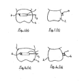
- an orthodontic fixed appliance includes a bracket, called a tube 1 that is affixed to a molar tooth 2.
- a wire 3 the protruding portion of which, in the prior art, is then bent at an angle to create a turned end 4 as it emerges from the tube behind the molar tooth.
- the bending of the wire 3 to create the turned end 4 is designed to do two things. The first is to help prevent the wire 3 from being pulled back forwards through the tube 1 accidentally. The second is that it presents a curved profile of wire 3 rather than a cut and sharp end which might cause trauma to the cheeks of the patient.
- creating an adequate angle to achieve a satisfactory result, especially in small diameter flexible-alloy wires is difficult. Often the wire 3 still pulls through the tube 1 and sometimes the turned end 4 unbends between appointments so that a sharp end is produced.
- a safety attachment A consists of four portions:
- the safety attachment A When viewed from the end as in Figure 2(b) , the safety attachment A resembles a split-shot weight as used in angling, with upper and lower portions 12 and 13 that are connected on one side only by a thin area of metal which acts as a hinge 10. The internal faces 11 of the upper and lower portions 12 and 13 are serrated to increase grip on the wire 3.
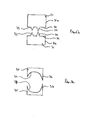
- the safety attachment A is applied to the wire 3 using specially designed pliers the upper beak 14 and lower beak 18 of which are shown schematically.
- the beaks 14, 18 are formed integrally with or secured to arms of pliers in conventional manner to provide the entire tool.
- the upper beak 14 carries three blades 15, 16 and 17.
- the first blade 15 is to crimp the wire-retaining portion 8 so that it grips the wire 3.
- the second blade 16 is to cut through the connecting isthmus 7.
- the third blade 17 is to crimp the safe-end portion 6 so that it grips the wire 3.
- the lower beak 18 carries one blade 19 to fit under the connecting isthmus 7 and which is aligned with the second blade 16 of the upper beak 14, this ensures that when the pliers are closed there is a clean cut of both the isthmus 7 and the wire 3.
- the crimping blades 15 and 17 may be multiple blades and/or broad flat ended blades in order to provide the best crimping action without risk of cutting through the portions 6 and 8 of the safety attachment A.
- the lower beak 18 also includes an upstand 20 within which is provided a recess 20a, with an opening 20b facing the blade 19.
- the recess 20a is shaped for receipt of the retaining lug 9.
- the lug 9 and recess 20a cooperate to prevent the safety attachment A being accidentally dislodged during use in the patient's mouth, and to ensure that the wire retaining portion 8 and wire fragment are safely removed from the patent's mouth.
- a bore 21 runs vertically through the upstand 20 from the outer face of the lower beak 18 and the recess 20a. The bore 21 is provided to allow insertion of a dental probe or similar instrument to remove the lug 9 and retained wire fragment following attachment of the safe-end 6 to the wire 3 in the patent's mouth. The lug 9 and retained wire fragment can thus be dropped directly into a secure sharps container in accordance with health and safety procedures.
- the safety attachment A is illustrated, showing the safe-end 6 in place on the end of the wire 3.
- the safe-end 6 is shaped to have no sharp edges, that is to be spherical or ovoid or the like, in order to minimise the chances that it can cause any damage to the cheeks of a patient.
- the safety attachment A can be used for all wires to apply a safe-end 6 as an anti-pull-through device and so as to ensure patients are protected from wire-pokes.
- a second embodiment of a safety attachment B according to the invention is illustrated with parts common to the first embodiment being like referenced, but with the addition of a "'".
- the safety attachment B is for use where there is no requirement to remove any of the wire 3, that is the wire 3 is already of the correct length, and thus no wire fragment needs to be retained and removed from the patient's mouth.
- the safety attachment B simply comprises a safe-end 6' and a retaining lug 9' connected by an isthmus 7', these parts being substantially as previously described with reference to safety attachment A.
- upper beak 22 and lower beak 25 of pliers designed for application of safety attachment B are illustrated schematically.
- the upper beak 22 carries only two blades 23 and 24.
- the first blade 23 is designed to cut through the isthmus 7' but not through the wire 3.
- the first blade 23 does not extend the full width of the upper beak 23, so as to avoid impinging on the wire 23.
- the second blade 24, which may be a multiple blade and/or which may be a flat ended broad blade, is designed to crimp the safe-end portion 6 onto the wire 3 so that it is safely retained.
- the safety attachment C comprises a safe-end 6" which has an indentation 26 in its lower surface.
- upper beak 27 and lower beak 29 of pliers designed for application of safety attachment C are illustrated schematically.
- the upper beak 27 is provided with two blades 28 designed to crimp the safe-end 6" onto the wire 3.
- the lower beak 29 carries a protrusion 30, running parallel to and between the blades 28 on the upper beak 27.
- Retention of the safety attachment C on the pliers is provided by friction between the protrusion 30 and the indentation 26, because they are an interference fit.
- the interference fit is only provided in direction Y-Y or direction X-X and not both directions. This is to ensure that there is sufficient freedom between the pliers and the safe-end 6" after application to the wire 3 to allow release of the pliers from the safe-end 6".
- the safety attachment D comprises a safe-end 6''', but being a simplified version of safety attachment C does not have an indentation in its lower surface.
- the safety attachment E comprises a safe-end 6"", which has a groove 38 running along its upper surface.
- the safety attachment F comprises a safe-end 6''''' which has a groove 38 running along its upper surface and a ridge extending along its lower surface, the groove 38 and the ridge 40 running substantially parallel to each other and substantially perpendicular to the hinge 10 joining the upper and lower portions 12, 13.
- the ridge 40 is provided to assist in retaining the safety attachment F in the beaks of pliers when it is being fitted in a patient's mouth.
- upper beak 39 and lower beak 41 of pliers designed for application of safety attachment D, E or F are illustrated schematically.
- the upper beak 39 has a blade 40 on its midline designed to crimp the safety attachment onto an orthodontic wire 3, but also to engage in the groove 38 when being used to fit safety attachment E or F.
- the lower beak 41 is shaped, with extensions 42 and a central recess 44, so as to accept safety attachment D, E or F and support it during insertion into the mouth, whilst also permitting deformation of the safety attachment D, E or F during crimping.
- the chosen safety attachment is inserted into the lower beak of the respective pliers, and retained as described above.
- the upper beak of the pliers is closed gently onto the safety attachment to further secure it. It is then possible to safely transfer the safety attachment, in the pliers, into the mouth of the patient without risk of the safety attachment being dislodged or dropped within the oral cavity even if the pliers are inverted during insertion. This permits safe use in all four corners of the mouth.
- the pliers are constructed with an angle of between 80° and 145° between the beaks and the handles (not shown) so as to facilitate access to the wire protruding from the tube on the last most tooth.
- the safety attachment having its hinge part 10 to the hinge of the pliers (not shown) and offering its open aspect to the outside of the pliers, is placed over the wire until the wire is hard up to the hinge part 10 of the safety attachment.
- the handles of the pliers are then squeezed together firmly.
- This action crimps the safety attachment onto the wire and, for attachments A and B also clips through the retaining lug 9 or 9' so as to allow the pliers to be removed, leaving the safe end 6, 6', 6", 6''', 6'''' or 6'''' on the wire.
- beaks of pliers designed to clip the protruding portion of the wire 3 to a specific length such that, when a selected safety attachment, as previously described, is applied the sharp end of the wire will be safely enclosed within the safe end thereof.
- the pliers have upper and lower beaks 31, which each carry first blades 32 and second blades 33, which are opposed to the corresponding blades on the other beak 31.
- the first blades 32 are longer than the second blades 33, such that the first blades 32 sever the wire whilst the second blades 33 retain the excised fragment for safe removal from the patient's mouth.
- Faces 31a of the beaks 31 are placed against the rear of the last most tooth during the cutting process and plain section 34 of the beaks 31 acts as a spacer to ensure that the wire 3 is cut so as to leave the correct length of protruding portion behind the last most tooth.
- Upper and lower beaks 35 each include a blade 36 for cutting the wire 3 immediately behind the last most tooth, and a recess 37 for receipt of the safe end being removed. As the blades 36 cut the wire the remainder of each beak 35 receives and grips the safe end with the previously protruding portion of the wire embedded in it, retaining it for safe removal from the patient's mouth.
Landscapes
- Health & Medical Sciences (AREA)
- Oral & Maxillofacial Surgery (AREA)
- Dentistry (AREA)
- Epidemiology (AREA)
- Life Sciences & Earth Sciences (AREA)
- Animal Behavior & Ethology (AREA)
- General Health & Medical Sciences (AREA)
- Public Health (AREA)
- Veterinary Medicine (AREA)
- Engineering & Computer Science (AREA)
- Mechanical Engineering (AREA)
- Dental Tools And Instruments Or Auxiliary Dental Instruments (AREA)
Claims (14)
- Ein Sicherungselement, das speziell zum Anbringen an kieferorthopädischem Draht im Mund eines Patienten ausgelegt ist, wobei das Sicherungselement einen Sicherungsendabschnitt (6) zum Crimpen auf den kieferorthopädischen Draht (3) umfasst, der nach dem Positionieren auf dem Draht keine scharfen Kanten aufweist, wobei er obere und untere Abschnitte umfasst, die durch ein Gelenk (10), das durch eine den oberen und unteren Abschnitt miteinander verbindende Verengung gebildet wird, aneinander gesichert sind.
- Ein Sicherungselement nach Anspruch 1, wobei es ferner Mittel zum Halten mit einer Anbringungszange beinhaltet.
- Ein Sicherungselement nach Anspruch 2, wobei das Mittel zum Halten mit einer Anbringungszange eine Vertiefung oder einen Vorsprung auf der Unterseite des Elements oder auf der Oberseite des Elements umfasst.
- Ein Sicherungselement nach Anspruch 3, wobei das Mittel zum Halten mit einer Anbringungszange einen Ansatz umfasst.
- Ein Sicherungselement nach Anspruch 4, wobei der Ansatz durch eine Verengung am Sicherungsendabschnitt gesichert wird.
- Ein Sicherungselement nach Anspruch 4, wobei es ferner einen Drahtstück-Halteabschnitt umfasst, der auf das Ende des Drahtes gecrimpt wird, um ein Stück zu halten, das während des Anbringungsvorgangs vom Ende des Drahtes abgeschnitten wird.
- Ein Sicherungselement nach Anspruch 6, wobei ein Drahtstück-Halteabschnitt auf einer Seite am Sicherungsendabschnitt durch eine Verengung und auf der anderen Seite am Ansatz gesichert wird.
- Ein Sicherungselement nach einem beliebigen der vorangegangenen Ansprüche, wobei der obere und der untere Abschnitt gegenüberliegende Vorderseiten aufweisen, wobei eine oder beide davon texturiert ist bzw. sind, um dabei zu helfen, dass es nach dem Crimpen am kieferorthopädischen Draht gehalten wird.
- Ein System umfassend ein Sicherungselement nach einem beliebigen der Ansprüche 1 bis 8 und eine Zange, die speziell zum Anbringen des Sicherungselements ausgelegt ist, wobei die Zange einen oberen und einen unteren Schnabel aufweist, wobei der obere Schnabel Mittel zum Crimpen des Sicherungsendes auf einen kieferorthopädischen Draht beinhaltet und der untere Schnabel Mittel zum Halten des Sicherungselements vor dem Anbringen des Sicherungsendes am Draht beinhaltet und sie nach dem Anbringen das Sicherungsende freigeben und es im Mund des Patienten auf dem Draht in Position belassen.
- Ein System nach Anspruch 9 soweit von Anspruch 3 abhängig, wobei das Mittel zum Halten des Sicherungselements einen Vorsprung umfasst, der für eine Presspassung mit der Vertiefung auf der Unterseite oder Oberseite des Elements sorgt.
- Ein System nach Anspruch 10, wobei für die Presspassung nur in einer Richtung und nicht zwei gesorgt wird.
- Ein System nach Anspruch 10 soweit von Anspruch 6 abhängig, wobei der obere Schnabel Mittel zum Crimpen des Drahtstück-Halteabschnitts auf den Draht beinhaltet.
- Ein System nach Anspruch 9 soweit von Anspruch 4 oder 5 abhängig, wobei der untere Schnabel eine Aussparung zur Aufnahme des Ansatzes des Sicherungselements beinhaltet.
- Ein System umfassend ein Sicherungselement nach einem beliebigen der Ansprüche 1 bis 8 und eine Zange, die speziell zum Entfernen eines Sicherungselements aus dem Mund eines Patienten ausgelegt ist, wobei besagte Zange einen oberen und einen unteren Schnabel jeweils mit einem Schneidmesser und einem Sicherungsende-Halteabschnitt in Form einer Aussparung aufweist.
Applications Claiming Priority (2)
| Application Number | Priority Date | Filing Date | Title |
|---|---|---|---|
| GB0700495A GB2445540A (en) | 2007-01-11 | 2007-01-11 | Safety attachment for orthodontic wires and pliers to apply attachment |
| PCT/GB2008/000018 WO2008084198A2 (en) | 2007-01-11 | 2008-01-04 | Safety attachment for orthodontic wires and pliers to apply attachment |
Publications (2)
| Publication Number | Publication Date |
|---|---|
| EP2106246A2 EP2106246A2 (de) | 2009-10-07 |
| EP2106246B1 true EP2106246B1 (de) | 2014-05-21 |
Family
ID=37809772
Family Applications (1)
| Application Number | Title | Priority Date | Filing Date |
|---|---|---|---|
| EP08701738.0A Not-in-force EP2106246B1 (de) | 2007-01-11 | 2008-01-04 | Sicherungselement für kieferorthopädische Drähte und Zange zum Anbringen des Sicherungselements |
Country Status (4)
| Country | Link |
|---|---|
| US (1) | US8246350B2 (de) |
| EP (1) | EP2106246B1 (de) |
| GB (1) | GB2445540A (de) |
| WO (1) | WO2008084198A2 (de) |
Families Citing this family (3)
| Publication number | Priority date | Publication date | Assignee | Title |
|---|---|---|---|---|
| US9084652B2 (en) | 2013-03-13 | 2015-07-21 | Ultimate Wireforms, Inc. | Archwire assembly with non-linear crimpable orthodontic stop and method of manufacture |
| KR20200025016A (ko) * | 2018-08-29 | 2020-03-10 | 오스템임플란트 주식회사 | 치아 교정용 와이어 |
| KR102107138B1 (ko) * | 2018-08-31 | 2020-05-07 | 오스템임플란트 주식회사 | 치아 교정 장치 |
Citations (1)
| Publication number | Priority date | Publication date | Assignee | Title |
|---|---|---|---|---|
| US5306142A (en) * | 1992-08-07 | 1994-04-26 | Tp Orthodontics, Inc. | Crimpable orthodontic hook |
Family Cites Families (30)
| Publication number | Priority date | Publication date | Assignee | Title |
|---|---|---|---|---|
| US1464807A (en) * | 1922-03-28 | 1923-08-14 | Michael J Clark | Dental instrument |
| US1898212A (en) * | 1931-08-17 | 1933-02-21 | Polcini Ralph | Carrier terminal |
| US2765686A (en) * | 1954-08-04 | 1956-10-09 | Walter W Deline | Split shot tool with reservoir |
| US2904924A (en) * | 1957-08-02 | 1959-09-22 | Frank K Tashiro | Shot-type fishing sinker |
| US3084469A (en) * | 1959-04-07 | 1963-04-09 | Thomas H Stratton | Fishing sinkers |
| US3597823A (en) * | 1969-01-30 | 1971-08-10 | Averd G Nelson | Pinch-on fishing sinker applier and assembly |
| US3581400A (en) * | 1969-10-29 | 1971-06-01 | Ormco Corp | Distal end cutter |
| US3914976A (en) * | 1974-05-09 | 1975-10-28 | Harold A Karr | Split shot applicator |
| US4348808A (en) * | 1980-12-15 | 1982-09-14 | Nalbandyan Harutyun G | Harvesting tool |
| DE3149544C1 (de) * | 1981-12-15 | 1983-07-07 | Dentaurum Hans-Peter Winkelstroeter Kg, 7536 Ispringen | Knopfanker für kieferorthopädische Geräte |
| US4395824A (en) * | 1982-02-10 | 1983-08-02 | Micro Dent Industries, Inc. | Wire cutting tool particularly for orthodontists |
| US4639219A (en) * | 1982-02-22 | 1987-01-27 | American Orthodontics Corporation | Surgical ball hooks |
| US4817602A (en) * | 1984-08-23 | 1989-04-04 | Dan Beraha | Vasectomy instrument |
| US4682598A (en) * | 1984-08-23 | 1987-07-28 | Dan Beraha | Vasectomy instrument |
| US4807622A (en) * | 1985-09-20 | 1989-02-28 | Kato Hatsujo Kaisha, Ltd. | Tube cutting and separating implement for conduit of blood or the like |
| US4716886A (en) * | 1986-05-01 | 1988-01-05 | Norman Schulman | Umbilical cord clamp and cutters |
| US4797094A (en) * | 1987-12-07 | 1989-01-10 | Karwoski Thaddeus M | Orthodontic wire terminal and attachment tool therefor |
| DE4006111C1 (de) * | 1990-02-27 | 1991-05-08 | Orbis-Werk Groten Gmbh + Co Kg, 4422 Ahaus, De | |
| US5037296A (en) * | 1990-08-27 | 1991-08-06 | Karwoski Thaddeus M | Lip protector from orthodontic wires and brackets |
| US5344315A (en) * | 1993-12-02 | 1994-09-06 | Hamilton Ortho Inc. | Multi-strand orthodontic arch wires and methods for use thereof |
| US6015417A (en) * | 1996-01-25 | 2000-01-18 | Reynolds, Jr.; Walker | Surgical fastener |
| US6161326A (en) * | 1996-05-21 | 2000-12-19 | Ratte; Geoffrey S. | Fishing line clamp |
| US5766005A (en) * | 1997-03-27 | 1998-06-16 | Casey; Kevin M. | Wire end protection cap assembly |
| US5910008A (en) * | 1998-02-26 | 1999-06-08 | Acme-Monaco Corporation | Archwire with posts |
| US20020076672A1 (en) * | 2000-09-21 | 2002-06-20 | Enoch Harold O. | Emergency orthodontics kit of components including a wire cutting and retention tool |
| US7182595B2 (en) * | 2002-01-04 | 2007-02-27 | Hu-Friedy Mfg. Co., Inc. | Distal end cutter |
| US20050019718A1 (en) * | 2003-07-22 | 2005-01-27 | Hanson G. Herbert | Orthodontic devices for use with arch wires |
| US7713057B2 (en) * | 2005-01-10 | 2010-05-11 | De Salazar Vinas Maria Pilar | Oral mucous membrane protector for orthodontic applications |
| US20070042314A1 (en) * | 2005-08-22 | 2007-02-22 | David Brosius | Crimpable orthodontic device |
| US20090013585A1 (en) * | 2007-07-13 | 2009-01-15 | Arthur Keith Acworth | Split shot |
-
2007
- 2007-01-11 GB GB0700495A patent/GB2445540A/en not_active Withdrawn
-
2008
- 2008-01-04 EP EP08701738.0A patent/EP2106246B1/de not_active Not-in-force
- 2008-01-04 WO PCT/GB2008/000018 patent/WO2008084198A2/en not_active Ceased
- 2008-01-04 US US12/521,383 patent/US8246350B2/en not_active Expired - Fee Related
Patent Citations (1)
| Publication number | Priority date | Publication date | Assignee | Title |
|---|---|---|---|---|
| US5306142A (en) * | 1992-08-07 | 1994-04-26 | Tp Orthodontics, Inc. | Crimpable orthodontic hook |
Also Published As
| Publication number | Publication date |
|---|---|
| WO2008084198A3 (en) | 2008-09-12 |
| GB2445540A (en) | 2008-07-16 |
| GB0700495D0 (en) | 2007-02-21 |
| WO2008084198A2 (en) | 2008-07-17 |
| US8246350B2 (en) | 2012-08-21 |
| US20100323316A1 (en) | 2010-12-23 |
| EP2106246A2 (de) | 2009-10-07 |
Similar Documents
| Publication | Publication Date | Title |
|---|---|---|
| US12090025B2 (en) | Orthodontic appliance with non-sliding archform | |
| US12193908B2 (en) | Orthodontic appliance with non-sliding archform | |
| KR102183854B1 (ko) | 치과교정용 그리핑 장치 | |
| US8485816B2 (en) | Orthodontic bracket having an archwire channel and archwire retaining mechanism | |
| US5906486A (en) | Self-ligating orthodontic brackets | |
| EP4287986B1 (de) | Orthodontische vorrichtung und orthodontisches system | |
| US20080081310A1 (en) | Reduced-friction buccal tube and method of use | |
| US20070134612A1 (en) | Dento-facial orthopedic treatment and orthodontic arch wire for implementing the same | |
| EP0225794B1 (de) | Orthodontisches Gerät | |
| BRPI0813295B1 (pt) | Bráquete Ortodôntico | |
| US20080305450A1 (en) | Placement jig for an orthodontic device | |
| EP1247497B1 (de) | Zange zur orthodontischen Behandlung | |
| US8246350B2 (en) | Safety attachment for orthodontic wires and pliers to apply attachment | |
| US20140295369A1 (en) | Orthodontic Accessory | |
| JP6950903B2 (ja) | 歯科矯正用のブラケット | |
| US20100190128A1 (en) | Orthodontic arch wire and method for using the same | |
| WO2010123674A1 (en) | Ceramic orthodontic bracket including debonding channel | |
| US4600381A (en) | Orthodontic bracket remover | |
| CN113967090A (zh) | 一种双丝托槽矫治装置及矫正方法 | |
| JP2003079643A (ja) | 歯科用プライヤおよび歯列矯正用ブラケットの取り外し方法 | |
| WO2007142560A1 (en) | Placement jig for an orthodontic device | |
| WO2002100288A2 (en) | Low profile matrix band retainers |
Legal Events
| Date | Code | Title | Description |
|---|---|---|---|
| PUAI | Public reference made under article 153(3) epc to a published international application that has entered the european phase |
Free format text: ORIGINAL CODE: 0009012 |
|
| 17P | Request for examination filed |
Effective date: 20090803 |
|
| AK | Designated contracting states |
Kind code of ref document: A2 Designated state(s): AT BE BG CH CY CZ DE DK EE ES FI FR GB GR HR HU IE IS IT LI LT LU LV MC MT NL NO PL PT RO SE SI SK TR |
|
| DAX | Request for extension of the european patent (deleted) | ||
| 17Q | First examination report despatched |
Effective date: 20130626 |
|
| GRAP | Despatch of communication of intention to grant a patent |
Free format text: ORIGINAL CODE: EPIDOSNIGR1 |
|
| INTG | Intention to grant announced |
Effective date: 20131217 |
|
| GRAS | Grant fee paid |
Free format text: ORIGINAL CODE: EPIDOSNIGR3 |
|
| GRAA | (expected) grant |
Free format text: ORIGINAL CODE: 0009210 |
|
| AK | Designated contracting states |
Kind code of ref document: B1 Designated state(s): AT BE BG CH CY CZ DE DK EE ES FI FR GB GR HR HU IE IS IT LI LT LU LV MC MT NL NO PL PT RO SE SI SK TR |
|
| REG | Reference to a national code |
Ref country code: GB Ref legal event code: FG4D |
|
| REG | Reference to a national code |
Ref country code: CH Ref legal event code: EP |
|
| REG | Reference to a national code |
Ref country code: AT Ref legal event code: REF Ref document number: 669202 Country of ref document: AT Kind code of ref document: T Effective date: 20140615 |
|
| REG | Reference to a national code |
Ref country code: IE Ref legal event code: FG4D |
|
| REG | Reference to a national code |
Ref country code: DE Ref legal event code: R096 Ref document number: 602008032388 Country of ref document: DE Effective date: 20140703 |
|
| REG | Reference to a national code |
Ref country code: NL Ref legal event code: VDEP Effective date: 20140521 Ref country code: AT Ref legal event code: MK05 Ref document number: 669202 Country of ref document: AT Kind code of ref document: T Effective date: 20140521 |
|
| REG | Reference to a national code |
Ref country code: LT Ref legal event code: MG4D |
|
| PG25 | Lapsed in a contracting state [announced via postgrant information from national office to epo] |
Ref country code: LT Free format text: LAPSE BECAUSE OF FAILURE TO SUBMIT A TRANSLATION OF THE DESCRIPTION OR TO PAY THE FEE WITHIN THE PRESCRIBED TIME-LIMIT Effective date: 20140521 Ref country code: IS Free format text: LAPSE BECAUSE OF FAILURE TO SUBMIT A TRANSLATION OF THE DESCRIPTION OR TO PAY THE FEE WITHIN THE PRESCRIBED TIME-LIMIT Effective date: 20140921 Ref country code: NO Free format text: LAPSE BECAUSE OF FAILURE TO SUBMIT A TRANSLATION OF THE DESCRIPTION OR TO PAY THE FEE WITHIN THE PRESCRIBED TIME-LIMIT Effective date: 20140821 Ref country code: GR Free format text: LAPSE BECAUSE OF FAILURE TO SUBMIT A TRANSLATION OF THE DESCRIPTION OR TO PAY THE FEE WITHIN THE PRESCRIBED TIME-LIMIT Effective date: 20140822 Ref country code: FI Free format text: LAPSE BECAUSE OF FAILURE TO SUBMIT A TRANSLATION OF THE DESCRIPTION OR TO PAY THE FEE WITHIN THE PRESCRIBED TIME-LIMIT Effective date: 20140521 |
|
| PG25 | Lapsed in a contracting state [announced via postgrant information from national office to epo] |
Ref country code: AT Free format text: LAPSE BECAUSE OF FAILURE TO SUBMIT A TRANSLATION OF THE DESCRIPTION OR TO PAY THE FEE WITHIN THE PRESCRIBED TIME-LIMIT Effective date: 20140521 Ref country code: ES Free format text: LAPSE BECAUSE OF FAILURE TO SUBMIT A TRANSLATION OF THE DESCRIPTION OR TO PAY THE FEE WITHIN THE PRESCRIBED TIME-LIMIT Effective date: 20140521 Ref country code: LV Free format text: LAPSE BECAUSE OF FAILURE TO SUBMIT A TRANSLATION OF THE DESCRIPTION OR TO PAY THE FEE WITHIN THE PRESCRIBED TIME-LIMIT Effective date: 20140521 Ref country code: HR Free format text: LAPSE BECAUSE OF FAILURE TO SUBMIT A TRANSLATION OF THE DESCRIPTION OR TO PAY THE FEE WITHIN THE PRESCRIBED TIME-LIMIT Effective date: 20140521 Ref country code: SE Free format text: LAPSE BECAUSE OF FAILURE TO SUBMIT A TRANSLATION OF THE DESCRIPTION OR TO PAY THE FEE WITHIN THE PRESCRIBED TIME-LIMIT Effective date: 20140521 Ref country code: PL Free format text: LAPSE BECAUSE OF FAILURE TO SUBMIT A TRANSLATION OF THE DESCRIPTION OR TO PAY THE FEE WITHIN THE PRESCRIBED TIME-LIMIT Effective date: 20140521 |
|
| PG25 | Lapsed in a contracting state [announced via postgrant information from national office to epo] |
Ref country code: PT Free format text: LAPSE BECAUSE OF FAILURE TO SUBMIT A TRANSLATION OF THE DESCRIPTION OR TO PAY THE FEE WITHIN THE PRESCRIBED TIME-LIMIT Effective date: 20140922 |
|
| PG25 | Lapsed in a contracting state [announced via postgrant information from national office to epo] |
Ref country code: DK Free format text: LAPSE BECAUSE OF FAILURE TO SUBMIT A TRANSLATION OF THE DESCRIPTION OR TO PAY THE FEE WITHIN THE PRESCRIBED TIME-LIMIT Effective date: 20140521 Ref country code: SK Free format text: LAPSE BECAUSE OF FAILURE TO SUBMIT A TRANSLATION OF THE DESCRIPTION OR TO PAY THE FEE WITHIN THE PRESCRIBED TIME-LIMIT Effective date: 20140521 Ref country code: CZ Free format text: LAPSE BECAUSE OF FAILURE TO SUBMIT A TRANSLATION OF THE DESCRIPTION OR TO PAY THE FEE WITHIN THE PRESCRIBED TIME-LIMIT Effective date: 20140521 Ref country code: EE Free format text: LAPSE BECAUSE OF FAILURE TO SUBMIT A TRANSLATION OF THE DESCRIPTION OR TO PAY THE FEE WITHIN THE PRESCRIBED TIME-LIMIT Effective date: 20140521 Ref country code: BE Free format text: LAPSE BECAUSE OF FAILURE TO SUBMIT A TRANSLATION OF THE DESCRIPTION OR TO PAY THE FEE WITHIN THE PRESCRIBED TIME-LIMIT Effective date: 20140521 Ref country code: RO Free format text: LAPSE BECAUSE OF FAILURE TO SUBMIT A TRANSLATION OF THE DESCRIPTION OR TO PAY THE FEE WITHIN THE PRESCRIBED TIME-LIMIT Effective date: 20140521 |
|
| REG | Reference to a national code |
Ref country code: DE Ref legal event code: R097 Ref document number: 602008032388 Country of ref document: DE |
|
| PG25 | Lapsed in a contracting state [announced via postgrant information from national office to epo] |
Ref country code: NL Free format text: LAPSE BECAUSE OF FAILURE TO SUBMIT A TRANSLATION OF THE DESCRIPTION OR TO PAY THE FEE WITHIN THE PRESCRIBED TIME-LIMIT Effective date: 20140521 |
|
| PLBE | No opposition filed within time limit |
Free format text: ORIGINAL CODE: 0009261 |
|
| STAA | Information on the status of an ep patent application or granted ep patent |
Free format text: STATUS: NO OPPOSITION FILED WITHIN TIME LIMIT |
|
| 26N | No opposition filed |
Effective date: 20150224 |
|
| PG25 | Lapsed in a contracting state [announced via postgrant information from national office to epo] |
Ref country code: IT Free format text: LAPSE BECAUSE OF FAILURE TO SUBMIT A TRANSLATION OF THE DESCRIPTION OR TO PAY THE FEE WITHIN THE PRESCRIBED TIME-LIMIT Effective date: 20140521 |
|
| REG | Reference to a national code |
Ref country code: DE Ref legal event code: R097 Ref document number: 602008032388 Country of ref document: DE Effective date: 20150224 |
|
| PG25 | Lapsed in a contracting state [announced via postgrant information from national office to epo] |
Ref country code: SI Free format text: LAPSE BECAUSE OF FAILURE TO SUBMIT A TRANSLATION OF THE DESCRIPTION OR TO PAY THE FEE WITHIN THE PRESCRIBED TIME-LIMIT Effective date: 20140521 |
|
| REG | Reference to a national code |
Ref country code: CH Ref legal event code: PL |
|
| PG25 | Lapsed in a contracting state [announced via postgrant information from national office to epo] |
Ref country code: LU Free format text: LAPSE BECAUSE OF FAILURE TO SUBMIT A TRANSLATION OF THE DESCRIPTION OR TO PAY THE FEE WITHIN THE PRESCRIBED TIME-LIMIT Effective date: 20150104 |
|
| PG25 | Lapsed in a contracting state [announced via postgrant information from national office to epo] |
Ref country code: MC Free format text: LAPSE BECAUSE OF FAILURE TO SUBMIT A TRANSLATION OF THE DESCRIPTION OR TO PAY THE FEE WITHIN THE PRESCRIBED TIME-LIMIT Effective date: 20140521 |
|
| PG25 | Lapsed in a contracting state [announced via postgrant information from national office to epo] |
Ref country code: LI Free format text: LAPSE BECAUSE OF NON-PAYMENT OF DUE FEES Effective date: 20150131 Ref country code: CH Free format text: LAPSE BECAUSE OF NON-PAYMENT OF DUE FEES Effective date: 20150131 |
|
| REG | Reference to a national code |
Ref country code: IE Ref legal event code: MM4A |
|
| REG | Reference to a national code |
Ref country code: FR Ref legal event code: PLFP Year of fee payment: 9 |
|
| PG25 | Lapsed in a contracting state [announced via postgrant information from national office to epo] |
Ref country code: IE Free format text: LAPSE BECAUSE OF NON-PAYMENT OF DUE FEES Effective date: 20150104 |
|
| PG25 | Lapsed in a contracting state [announced via postgrant information from national office to epo] |
Ref country code: MT Free format text: LAPSE BECAUSE OF FAILURE TO SUBMIT A TRANSLATION OF THE DESCRIPTION OR TO PAY THE FEE WITHIN THE PRESCRIBED TIME-LIMIT Effective date: 20140521 |
|
| REG | Reference to a national code |
Ref country code: FR Ref legal event code: PLFP Year of fee payment: 10 |
|
| PG25 | Lapsed in a contracting state [announced via postgrant information from national office to epo] |
Ref country code: HU Free format text: LAPSE BECAUSE OF FAILURE TO SUBMIT A TRANSLATION OF THE DESCRIPTION OR TO PAY THE FEE WITHIN THE PRESCRIBED TIME-LIMIT; INVALID AB INITIO Effective date: 20080104 Ref country code: BG Free format text: LAPSE BECAUSE OF FAILURE TO SUBMIT A TRANSLATION OF THE DESCRIPTION OR TO PAY THE FEE WITHIN THE PRESCRIBED TIME-LIMIT Effective date: 20140521 |
|
| PG25 | Lapsed in a contracting state [announced via postgrant information from national office to epo] |
Ref country code: CY Free format text: LAPSE BECAUSE OF FAILURE TO SUBMIT A TRANSLATION OF THE DESCRIPTION OR TO PAY THE FEE WITHIN THE PRESCRIBED TIME-LIMIT Effective date: 20140521 |
|
| PG25 | Lapsed in a contracting state [announced via postgrant information from national office to epo] |
Ref country code: TR Free format text: LAPSE BECAUSE OF FAILURE TO SUBMIT A TRANSLATION OF THE DESCRIPTION OR TO PAY THE FEE WITHIN THE PRESCRIBED TIME-LIMIT Effective date: 20140521 |
|
| REG | Reference to a national code |
Ref country code: FR Ref legal event code: PLFP Year of fee payment: 11 |
|
| PGFP | Annual fee paid to national office [announced via postgrant information from national office to epo] |
Ref country code: DE Payment date: 20180122 Year of fee payment: 11 |
|
| PGFP | Annual fee paid to national office [announced via postgrant information from national office to epo] |
Ref country code: FR Payment date: 20180122 Year of fee payment: 11 |
|
| REG | Reference to a national code |
Ref country code: DE Ref legal event code: R119 Ref document number: 602008032388 Country of ref document: DE |
|
| PG25 | Lapsed in a contracting state [announced via postgrant information from national office to epo] |
Ref country code: FR Free format text: LAPSE BECAUSE OF NON-PAYMENT OF DUE FEES Effective date: 20190131 Ref country code: DE Free format text: LAPSE BECAUSE OF NON-PAYMENT OF DUE FEES Effective date: 20190801 |
|
| PGFP | Annual fee paid to national office [announced via postgrant information from national office to epo] |
Ref country code: GB Payment date: 20220130 Year of fee payment: 15 |
|
| GBPC | Gb: european patent ceased through non-payment of renewal fee |
Effective date: 20230104 |
|
| PG25 | Lapsed in a contracting state [announced via postgrant information from national office to epo] |
Ref country code: GB Free format text: LAPSE BECAUSE OF NON-PAYMENT OF DUE FEES Effective date: 20230104 |