EP2106205B1 - Ruggedized, self aligning, sliding air seal for removable electronic units - Google Patents
Ruggedized, self aligning, sliding air seal for removable electronic units Download PDFInfo
- Publication number
- EP2106205B1 EP2106205B1 EP09002127.0A EP09002127A EP2106205B1 EP 2106205 B1 EP2106205 B1 EP 2106205B1 EP 09002127 A EP09002127 A EP 09002127A EP 2106205 B1 EP2106205 B1 EP 2106205B1
- Authority
- EP
- European Patent Office
- Prior art keywords
- chassis unit
- main chassis
- pair
- removable module
- mounting
- Prior art date
- Legal status (The legal status is an assumption and is not a legal conclusion. Google has not performed a legal analysis and makes no representation as to the accuracy of the status listed.)
- Active
Links
- 238000001816 cooling Methods 0.000 claims description 36
- 230000000712 assembly Effects 0.000 claims description 34
- 238000000429 assembly Methods 0.000 claims description 34
- 238000007789 sealing Methods 0.000 claims description 19
- 239000000463 material Substances 0.000 claims description 10
- 238000000034 method Methods 0.000 claims description 8
- 239000013536 elastomeric material Substances 0.000 claims description 5
- 230000013011 mating Effects 0.000 claims description 3
- 239000011248 coating agent Substances 0.000 claims 1
- 238000000576 coating method Methods 0.000 claims 1
- 230000009977 dual effect Effects 0.000 claims 1
- 238000004519 manufacturing process Methods 0.000 description 5
- 238000013461 design Methods 0.000 description 4
- 230000014759 maintenance of location Effects 0.000 description 4
- 239000003348 petrochemical agent Substances 0.000 description 3
- 239000002904 solvent Substances 0.000 description 3
- 238000005516 engineering process Methods 0.000 description 2
- 239000002783 friction material Substances 0.000 description 2
- 238000009434 installation Methods 0.000 description 2
- 239000002184 metal Substances 0.000 description 2
- 229920001296 polysiloxane Polymers 0.000 description 2
- 229920006362 Teflon® Polymers 0.000 description 1
- 238000004891 communication Methods 0.000 description 1
- 239000004020 conductor Substances 0.000 description 1
- 238000010276 construction Methods 0.000 description 1
- 230000007797 corrosion Effects 0.000 description 1
- 238000005260 corrosion Methods 0.000 description 1
- 238000011161 development Methods 0.000 description 1
- 238000006073 displacement reaction Methods 0.000 description 1
- 230000000694 effects Effects 0.000 description 1
- 230000007613 environmental effect Effects 0.000 description 1
- 238000002955 isolation Methods 0.000 description 1
- 238000012423 maintenance Methods 0.000 description 1
- 239000000126 substance Substances 0.000 description 1
Images


Classifications
-
- H—ELECTRICITY
- H05—ELECTRIC TECHNIQUES NOT OTHERWISE PROVIDED FOR
- H05K—PRINTED CIRCUITS; CASINGS OR CONSTRUCTIONAL DETAILS OF ELECTRIC APPARATUS; MANUFACTURE OF ASSEMBLAGES OF ELECTRICAL COMPONENTS
- H05K7/00—Constructional details common to different types of electric apparatus
- H05K7/20—Modifications to facilitate cooling, ventilating, or heating
- H05K7/20536—Modifications to facilitate cooling, ventilating, or heating for racks or cabinets of standardised dimensions, e.g. electronic racks for aircraft or telecommunication equipment
- H05K7/20554—Forced ventilation of a gaseous coolant
- H05K7/20563—Forced ventilation of a gaseous coolant within sub-racks for removing heat from electronic boards
-
- H—ELECTRICITY
- H05—ELECTRIC TECHNIQUES NOT OTHERWISE PROVIDED FOR
- H05K—PRINTED CIRCUITS; CASINGS OR CONSTRUCTIONAL DETAILS OF ELECTRIC APPARATUS; MANUFACTURE OF ASSEMBLAGES OF ELECTRICAL COMPONENTS
- H05K7/00—Constructional details common to different types of electric apparatus
- H05K7/14—Mounting supporting structure in casing or on frame or rack
- H05K7/1422—Printed circuit boards receptacles, e.g. stacked structures, electronic circuit modules or box like frames
- H05K7/1424—Card cages
Definitions
- the invention relates to the field of air seals, and more particularly to an air seal and retention system between an equipment housing and a removable module to deliver cooling air across or through electrical components mounted with the removable module.
- an air seal between an electronics rack and the removable electronics module that also provides a means to ensure low deflections during vibration through use of a fixed boundary condition. It is also desirable to have a sealing system which is resistant to jamming and misalignment and conducive to maintenance and repair. It is further preferred to have a sliding air seal which is cost effective and resistant to corrosive environmental conditions.
- Known systems for air cooling of removable electronic units use an elastomeric seal which is vulcanized into a channel shaped guide. This has proven to be a difficult method to manufacture the seal.
- the present invention vulcanizes the resilient seal to a flat, tapered surface which reduces cost, tooling, and manufacturing complexity.
- Known systems for air cooling of removable electronic units also use silicone as the material for the seals which are damaged by exposure to solvents and petro-chemical agents.
- the new invention uses a double layer of fluorosilicone material or other environmentally resistant material having two durometer values with one on top of the other, and enclosing the slotted opening that is coated with a low friction material on the upper elastomeric material to facilitate low sliding friction when an electronics module having a tapered surface is slid over and compresses the seal.
- the known systems for air cooling of removable electronic units utilize difficult to manufacture airseals that are difficult to field replace and are not resistant to chemical environments.
- the seal of the present invention also has a novel retention method that uses a tab on the bottom (m) and only requires one fastener at the top allowing the seal to be easily field replaceable.
- the main chassis unit has a pair of separated and opposing module mounting assemblies or walls of the electronics rack adapted to receive and secure a removable module between the latter opposing module mounting assemblies or walls.
- Each wall of the electronics rack supporting the electronics module contains an air deliver plenum.
- One plenum is a pressurized supply for the cooling air and the opposite side wall of the chassis collects and expends the exhaust cooling air.
- the electronics rack further includes a removable seal plate member having a base plate for securing to the electronics rack and an affixed elastomeric and resilient seal member surrounding an opening formed through the base plate and extending from a surface of the base plate. The seal member then forms a sealing air dam or duct about the cooling air entry and exhaust slots communicated through the cooling air inlet slots of the electronics rack.
- the module mounting assembly or wall of the electronics rack or main chassis housing also includes a pair of guide rails extending from the module mounting assembly or wall forming a U-shaped channel between the pair of guide rails for receiving one of the mounting edges of the removable module assembly.
- the guide system of the present invention has two surfaces extending beyond the sealing surface of the electronics module providing protection for that sealing surface from objects that could damage the surface. These extensions provide a physical stop that prevents large objects from striking the sealing surface.
- the guides are extended so that they are a constant distance from the electronics module thus reducing the "rocking" that jammed the prior known sealing methods for printed circuit modules cooled by a flow of air.
- the present invention reduces the frequency of failed installation of the module into the rack with the improved guide system.
- the present invention further improves the life expectancy of the module connector with the addition of a wedgelock to provide a fixed boundary condition at the module-rack interface.
- the air seal occupies less volume thus allowing for smaller rack designs.
- the fluorosilicone seal as described is also resistant to a broader range of petrochemicals and solvents.
- the removable module assembly 10 has a main body 12 that generally includes two opposing, vertical mounting edges 14, 16 and a connection edge 18. At least one of the mounting edges 14,16 of the removable mounting assembly 10 has an opening 20 to vent by receiving or passing a cooling air flow F into or from an interior cavity 22 of the main body or housing 12 of the removable module assembly 10.
- the cooling air flow F is to flow across the electronic circuitry within the removable module assembly 10 and provide a cooling environment.
- the air flow F can exit the interior of the removable module assembly 10 either through a portion of the opening 20 if there is a U-shaped air flow path within the module 10 or else be vented through another opening in an opposite mounting edge 16 or other vents formed in the main body 12 of the module 10.
- the electronic rack or main chassis unit M has at least one and preferably a pair of separated and opposing module mounting assemblies or walls 24, 26 adapted to receive and secure a compatible removable module 10 with a single module mounting assembly or wall 24 or between the opposing module mounting assemblies or walls 24, 26. At least one of the pair of the opposing module mounting assemblies or walls 24, 26 of the electronics rack M includes a plenum means 28 having an opening 30 for communicating the cooling air flow F to provide a cooling environment for the electronics contained within the removable module 10.
- the module mounting assembly 24,26 also includes a pair of guide rails 42a, 42b extending from the module mounting assembly 24, 26 forming a U-shaped channel 44 between the pair of guide rails 42a, 42b for receiving one of the mounting edges 64, 66 of the removable module assembly 10.
- the U-shaped channel 44 is preferably sized to be compatible for receiving the corresponding mounting edge 64, 66 of the module 10.
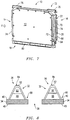
- the elastomeric material 48, 50 is formed having a tapered cross-section as shown in Fig. 8 with the top of the seal 84 in cross section being narrower than the base of the seal 86, and the sides in cross section sloping from the seal top 84 toward the wider seal base 86.
- the rubber bellows or air seal member 36 may be vulcanized to the metal frame or plate member 34.
- the seal plate member 34 is preferably removable and includes a mounting tongue or tang 54 at one end 56 and having an opposing end 58 adapted to be secured to the compatible module mounting assembly 24, 26 with a removable fastener 60, such as a screw or other known fastening means cooperating with the module mounting assembly 24, 26, and the module mounting assembly 24, 26 includes a receptacle 62 adapted to receive the finger 54 of the removable seal plate member 34.
- the known cooling systems for removable electronic units having air flow through electronics modules 10 do not provide a fixed boundary condition at the rack/module interface. The lack of this condition may cause excessive motion of the module 10 during vibration. This motion can produce fretting corrosion at the module-to-rack connector interface as well as electrical noise in sensitive electronics.
- the vibration in the removable module 10 originates externally to the chassis M such as when the device D is mounted within an aircraft.
- the vibration is transmitted into the chassis M that then mechanically conveys the vibration into a mounted or connected module 10.
- the present invention is a combined air seal, guide system, and retention method for containing cooling air between equipment racks M and electronics modules 10.
- the guide system on the electronics module provides alignment between the electronics rack or chassis M and the electronic module 10 and provides protection of the sealing surfaces on the electronics module 10.
- the guide system G is accomplished by positioning preferably two ribs 64, 66 on the module 10 to flank the air seal 36 which is installed in the electronics rack or main chassis M.
- the electronics rack or main chassis housing M also contains guide rails 42a, 42b to align the module M and provide a clamping surface 68.
- the module ribs 64, 66 are designed to be a constant distance from the rack M which reduces the misalignment that is present in the known systems for cooling removable electronic units 10 that use a tapered surface.
- the ribs 64, 66 also protrude beyond the module 10 sealing surface 70 thus protecting the surface 70 from objects that could damage the surface 70.
- the retention or latching mechanism 72 for the module 10 within the main chassis M is accomplished by using a wedgelock or latch mechanism 74.
- the wedgelock 74 is tightened using the fastener or lever arm 76 at the top of the removable module 10. It thus provides a fixed structural boundary condition at the compatible and corresponding module-rack interface 24, 26 by clamping the module 10 to the rack or chassis M.
- the fixed boundary condition provides a robust design for use in high vibration applications by preventing motion of the electronics module 10 that could compromise connector interface or the air seal integrity.
- wedgelock type 74 of latching or locking mechanism 72 minimizes undesirable motion in the removable module 10 caused by vibration.
- RF modules 10 require stiff structures and fixed boundary interface conditions.
- wedgelocks 74 historically have provided the best option for achieving minimal motion during dynamic conditions.
- Vibration within an electronic device D of the type including a main chassis unit or electronics rack M and at least one compatible and removable module assembly 10 mountable with the main chassis unit M for supporting electronic circuitry components 78 electro-optically coupled with the main chassis unit M and the removable module assembly 10 that is being cooled by a cooling air flow F from the main chassis unit M about the electronic circuitry 78 can be reduced by mounting of attaching the removable module assembly 10 to at least one module mounting assembly 24 or else preferably between a pair of separated and opposing module mounting assemblies 24, 26 of the main chassis unit M.
- the removable module assembly 10 is ruggedized by the present invention to increase the natural frequency of the removable module 10.
- the removable module assembly 10 has a main body 12 that generally includes two opposing mounting edges 14, 16 and a connection edge 18 as described above. At least one of the mounting edges 14, 16 of the removable mounting assembly 10 includes an opening 20 or other means to vent the cooling air flow F into an interior cavity 22 of the main body or housing 12 of the removable module assembly 10 from the main chassis unit M.
- At least one of the preferred pair of the opposing module mounting assemblies 24, 26 includes a plenum means 28 having an opening 30 for communicating the cooling air flow F into the module 10.
- the module mounting assembly 24, 26 of the main chassis unit or electronics rack M further includes a seal plate member 32 that is preferably removable having a base plate 34 for securing to the module mounting assembly 24 of the main chassis unit M and an affixed elastomeric and resilient seal member 36 that is surrounding an opening 38 formed through the base plate 34 and extending from a surface 40 of the base plate 38.
- the seal member 32 forms a sealing air dam about the cooling air flow F communicated through the plenum 28 of the module mounting assembly 24 of the main chassis unit M.
- the removable module assembly 10 further preferably includes latch means 72 for securing the removable module assembly 10 to the module mounting assembly 24 of the main chassis unit or electronics rack M.
- the removable module assembly 10 is then secured using the latch means 72 to a corresponding module mounting assembly 24 by locking one of the mounting edges of the removable module assembly 10 within the U-shaped channel 44.
Description
- The invention relates to the field of air seals, and more particularly to an air seal and retention system between an equipment housing and a removable module to deliver cooling air across or through electrical components mounted with the removable module.
- High power dissipating electronic assemblies require cooling air to be directed through a compact heat exchanger. This usually consists of a pair of printed circuit boards which may be bonded, or more likely fastened together by means of a frame positioned between the two modules. It is necessary to provide a reliable seal at each end of these modules to prevent leakage of any cooling air between the electronics rack and the removable module. Such leakage can have drastic effect on the system's thermal performance and overall reliability.
- It is desirable to have an air seal between an electronics rack and the removable electronics module that also provides a means to ensure low deflections during vibration through use of a fixed boundary condition. It is also desirable to have a sealing system which is resistant to jamming and misalignment and conducive to maintenance and repair. It is further preferred to have a sliding air seal which is cost effective and resistant to corrosive environmental conditions.
- Known systems for air cooling of removable electronic units use an elastomeric seal which is vulcanized into a channel shaped guide. This has proven to be a difficult method to manufacture the seal. The present invention vulcanizes the resilient seal to a flat, tapered surface which reduces cost, tooling, and manufacturing complexity.
- Known systems for air cooling of removable electronic units also use silicone as the material for the seals which are damaged by exposure to solvents and petro-chemical agents. The new invention uses a double layer of fluorosilicone material or other environmentally resistant material having two durometer values with one on top of the other, and enclosing the slotted opening that is coated with a low friction material on the upper elastomeric material to facilitate low sliding friction when an electronics module having a tapered surface is slid over and compresses the seal.
- The known systems for air cooling of removable electronic units utilize difficult to manufacture airseals that are difficult to field replace and are not resistant to chemical environments. The seal of the present invention also has a novel retention method that uses a tab on the bottom (m) and only requires one fastener at the top allowing the seal to be easily field replaceable.
- Historically, all airborne radar systems have used classic multiple stage vibration isolation systems to minimize undesirable motion to meet phase noise performance requirements, e.g.,3 stages for AWACS, APG-68, and B1-B. It has been shown that excessive motion during vibration has been determined to be the root cause of phase noise problems in legacy radar systems.
- Advances in electronic component technology has resulted in stiffer, higher frequency module structures. (Stiffer means less displacement for a given input.) The development of a wedgelock for use on RF modules was launched in the early 1980's. Wedgelock technology has been part of the solution to high vibration environments and has been used successfully to restrain RF modules on all programs commencing with the APG-68 and B1-B radar systems.
- Such sealing methods for printed circuit modules cooled by a flow of air include, for example,
U.S. Patent Number 4,375,290, issued March 1, 1983 to Alfred A. Zucchi et al . Other examples for background purposes areU.S. Patent Numbers. 2,843,806 ,3,956,673 ,4,006,388 , and4277815 . -
US 2006/0133033 A discloses an apparatus for housing and cooling circuit card assemblies employed in communication and other systems including a chassis having opposed end walls which are formed with a series of spaced inlet card guides and correspondingly spaced outlet card guides, respectively. A straight-pass heat exchanger is directly mounted to each circuit card assembly via thermally conductive material, and opposed ends of the heat exchanger are mounted by a wedge lock to respective inlet and outlet card guides. The heat exchanger employs unique and angled interface geometry that creates a gasketless airtight joint with complimentary inlet and outlet card guide geometry through which cooling air passes. - While the above cited references introduce and disclose a number of noteworthy advances and technological improvements within the art, none completely fulfills the specific objectives achieved by this invention. This is achieved by the subject matter of the independent claims.
- An electronics housing system adapted for electronic devices includes a main chassis unit and at least one removable module mountable with the base unit for supporting electronic circuitry components electrically or electro-optically coupled with the base unit. The removable module assembly has a main body that includes two opposing mounting edges and an electrical connection edge along the bottom. Both of the vertical mounting edges of the removable mounting assembly or wall of the electronics rack have a slotted opening. One side acts to supply the cooling air flow into an interior cavity of the removable module assembly. The opposing side of the rack has an opening to receive the exhaust of the cooling air from the removable module.
- The main chassis unit has a pair of separated and opposing module mounting assemblies or walls of the electronics rack adapted to receive and secure a removable module between the latter opposing module mounting assemblies or walls. Each wall of the electronics rack supporting the electronics module contains an air deliver plenum. One plenum is a pressurized supply for the cooling air and the opposite side wall of the chassis collects and expends the exhaust cooling air. The electronics rack further includes a removable seal plate member having a base plate for securing to the electronics rack and an affixed elastomeric and resilient seal member surrounding an opening formed through the base plate and extending from a surface of the base plate. The seal member then forms a sealing air dam or duct about the cooling air entry and exhaust slots communicated through the cooling air inlet slots of the electronics rack.
- The module mounting assembly or wall of the electronics rack or main chassis housing also includes a pair of guide rails extending from the module mounting assembly or wall forming a U-shaped channel between the pair of guide rails for receiving one of the mounting edges of the removable module assembly.
- The guide system of the present invention has two surfaces extending beyond the sealing surface of the electronics module providing protection for that sealing surface from objects that could damage the surface. These extensions provide a physical stop that prevents large objects from striking the sealing surface. In addition, the guides are extended so that they are a constant distance from the electronics module thus reducing the "rocking" that jammed the prior known sealing methods for printed circuit modules cooled by a flow of air.
- The present invention reduces the frequency of failed installation of the module into the rack with the improved guide system. The present invention further improves the life expectancy of the module connector with the addition of a wedgelock to provide a fixed boundary condition at the module-rack interface. The air seal occupies less volume thus allowing for smaller rack designs. The fluorosilicone seal as described is also resistant to a broader range of petrochemicals and solvents.
- These and other objects, advantages and preferred features of this invention will be apparent from the following description taken with reference to the accompanying drawings, wherein is shown the preferred embodiments of the invention.
- A more particular description of the invention briefly summarized above is available from the exemplary embodiments illustrated in the drawing and discussed in further detail below. Through this reference, it can be seen how the above cited features, as well as others that will become apparent, are obtained and can be understood in detail. The drawings nevertheless illustrate only typical, preferred embodiments of the invention and are not to be considered limiting of its scope as the invention may admit to other equally effective embodiments.
-
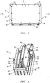
Figure 1 is a perspective view of the interior of the main chassis unit of the housing assembly with no removable modules installed. -
Figure 2 is a left frontal elevational view of a removable module. -
Figure 3 is a left side elevational view of the removable module ofFig. 2 . -
Figure 4 is a perspective view of the interior of the main chassis with one removable module being positioned. -
Figure 5 is a cross-sectional view of a removable module installed into an electronic chassis. -
Figure 6 is a perspective view of the seal plate member of the present invention. -
Figure 7 is a right frontal elevational view of a removable module having a wedgelock type of latching mechanism. -
Figure 8 is a cross-sectional view taken along line 8-8 inFigure 6 . - So that the manner in which the above recited features, advantages and objects of the present invention are attained can be understood in detail, more particular description of the invention, briefly summarized above, may be had by reference to the embodiment thereof that is illustrated in the appended drawings. In all the drawings, identical numbers represent the same elements.
- An electronics housing system S adapted for electronic devices D, such as radios, radars, transmitters, and the like, includes a main chassis unit or electronics rack
- M and at least one compatible and controllably
removable module assembly 10 mountable with the base unit or electronic rack M for supporting electronic circuitry components, such as a printedcircuit board 78, electrically or electro-optically coupled with the base unit M with cooperatingconnectors - The
removable module assembly 10 has amain body 12 that generally includes two opposing, vertical mounting edges 14, 16 and aconnection edge 18. At least one of the mounting edges 14,16 of the removable mountingassembly 10 has anopening 20 to vent by receiving or passing a cooling air flow F into or from aninterior cavity 22 of the main body orhousing 12 of theremovable module assembly 10. The cooling air flow F is to flow across the electronic circuitry within theremovable module assembly 10 and provide a cooling environment. The air flow F can exit the interior of theremovable module assembly 10 either through a portion of theopening 20 if there is a U-shaped air flow path within themodule 10 or else be vented through another opening in an opposite mountingedge 16 or other vents formed in themain body 12 of themodule 10. - The electronic rack or main chassis unit M has at least one and preferably a pair of separated and opposing module mounting assemblies or
walls removable module 10 with a single module mounting assembly orwall 24 or between the opposing module mounting assemblies orwalls walls opening 30 for communicating the cooling air flow F to provide a cooling environment for the electronics contained within theremovable module 10. - The module mounting wall or
assembly seal plate member 32 having abase plate 34 for securing to the module mounting wall orassembly resilient seal member 36 surrounding anopening 38 formed through thebase plate 34 and extending from asurface 40 of thebase plate 34. The seal member or rubber bellows 36 forms a sealing air dam or duct about the cooling air flow F communicated through theplenum 28 of themodule mounting assembly - The
module mounting assembly guide rails module mounting assembly U-shaped channel 44 between the pair ofguide rails removable module assembly 10. TheU-shaped channel 44 is preferably sized to be compatible for receiving the corresponding mountingedge module 10. - The sliding air seals 36 must work under a variety of conditions. The air seals 36 must operate in a wide variety of temperatures and exposure to corrosive materials. They also must resist tearing when the
electronics module 10 is installed and not fail under compressive loads. The optionally removableseal plate member 32 incorporates ametal base plate 34 having aslot opening 38 for the air passage F down the center and an inclinedupper surface 40 with respect to alower surface 46; a double layer ofelastomeric material low friction material 52, such as Teflon® or the like, on at least a portion of the upperelastomeric material 50 to facilitate low friction when anelectronics module 10 having a mating taperedsurface 70 is slid over and compresses theseal 36. In a preferred embodiment of theslidable seal 36, theelastomeric material Fig. 8 with the top of theseal 84 in cross section being narrower than the base of theseal 86, and the sides in cross section sloping from theseal top 84 toward thewider seal base 86. - The rubber bellows or
air seal member 36 may be vulcanized to the metal frame orplate member 34. - The known cooling systems for removable
electronic units 10 also use silicone as the material for the seals that can be damaged by exposure to solvents and petrochemical agents. The present invention addresses this shortcoming by using new materials, such as a double layer of fluorosilicone material or other environmentally resistant material having two durometer values, and the removable design to facilitate ease of manufacture. - Known systems use a combined seal and module guide which results in a part which is difficult to manufacture and replace in the field. However, the present invention places the guide rails on the module and makes the seal much easier to fabricate and replace (if needed).
- In a preferred embodiment of the
seal plate member 32, theseal plate member 34 is preferably removable and includes a mounting tongue ortang 54 at oneend 56 and having an opposingend 58 adapted to be secured to the compatiblemodule mounting assembly removable fastener 60, such as a screw or other known fastening means cooperating with themodule mounting assembly module mounting assembly receptacle 62 adapted to receive thefinger 54 of the removableseal plate member 34. - The known cooling systems for removable electronic units having air flow through
electronics modules 10 do not provide a fixed boundary condition at the rack/module interface. The lack of this condition may cause excessive motion of themodule 10 during vibration. This motion can produce fretting corrosion at the module-to-rack connector interface as well as electrical noise in sensitive electronics. - Generally, the vibration in the
removable module 10 originates externally to the chassis M such as when the device D is mounted within an aircraft. The vibration is transmitted into the chassis M that then mechanically conveys the vibration into a mounted or connectedmodule 10. - In addition, the known electronics module designs include a wedge shaped sealing surface, one that is wider at the top and narrower at the bottom near the connector interface at the
connector edge 18. This taper causes misalignment and jamming of themodule 10 in the rack M during installation. This condition can cause physical damage to the air seal and module sealing surface. - The present invention is a combined air seal, guide system, and retention method for containing cooling air between equipment racks M and
electronics modules 10. The guide system on the electronics module provides alignment between the electronics rack or chassis M and theelectronic module 10 and provides protection of the sealing surfaces on theelectronics module 10. The guide system G is accomplished by positioning preferably tworibs module 10 to flank theair seal 36 which is installed in the electronics rack or main chassis M. - The electronics rack or main chassis housing M also contains
guide rails surface 68. Themodule ribs electronic units 10 that use a tapered surface. Theribs module 10 sealingsurface 70 thus protecting thesurface 70 from objects that could damage thesurface 70. - The retention or latching
mechanism 72 for themodule 10 within the main chassis M is accomplished by using a wedgelock orlatch mechanism 74. Thewedgelock 74 is tightened using the fastener orlever arm 76 at the top of theremovable module 10. It thus provides a fixed structural boundary condition at the compatible and corresponding module-rack interface module 10 to the rack or chassis M. The fixed boundary condition provides a robust design for use in high vibration applications by preventing motion of theelectronics module 10 that could compromise connector interface or the air seal integrity. - The
wedgelock type 74 of latching or lockingmechanism 72 minimizes undesirable motion in theremovable module 10 caused by vibration.RF modules 10 require stiff structures and fixed boundary interface conditions. For plug-inmodules 10, wedgelocks 74 historically have provided the best option for achieving minimal motion during dynamic conditions. - In an alternative embodiment the
connection edge 18 and the electro-optical connector or plug 80 can be formed or merged with one of the mounting edges 14,16. I such an arrangement the interconnectingplug 80 may also function as one of theribs - Vibration within an electronic device D of the type including a main chassis unit or electronics rack M and at least one compatible and
removable module assembly 10 mountable with the main chassis unit M for supportingelectronic circuitry components 78 electro-optically coupled with the main chassis unit M and theremovable module assembly 10 that is being cooled by a cooling air flow F from the main chassis unit M about theelectronic circuitry 78 can be reduced by mounting of attaching theremovable module assembly 10 to at least onemodule mounting assembly 24 or else preferably between a pair of separated and opposingmodule mounting assemblies removable module assembly 10 is ruggedized by the present invention to increase the natural frequency of theremovable module 10. - The
removable module assembly 10 has amain body 12 that generally includes two opposing mountingedges connection edge 18 as described above. At least one of the mounting edges 14, 16 of the removable mountingassembly 10 includes anopening 20 or other means to vent the cooling air flow F into aninterior cavity 22 of the main body orhousing 12 of theremovable module assembly 10 from the main chassis unit M. - At least one of the preferred pair of the opposing
module mounting assemblies opening 30 for communicating the cooling air flow F into themodule 10. Themodule mounting assembly seal plate member 32 that is preferably removable having abase plate 34 for securing to themodule mounting assembly 24 of the main chassis unit M and an affixed elastomeric andresilient seal member 36 that is surrounding anopening 38 formed through thebase plate 34 and extending from asurface 40 of thebase plate 38. Theseal member 32 forms a sealing air dam about the cooling air flow F communicated through theplenum 28 of themodule mounting assembly 24 of the main chassis unit M. - The
module mounting assembly 24 of the main chassis unit M also includes a pair ofguide rails module mounting assembly 24 of the main chassis unit M forming aU-shaped channel 44 between the pair ofguide rails removable module assembly 10. One of the mounting edges 14, 16 of theremovable module assembly 10 is positioned within the compatibly formedU-shaped channel 44. The mounting edge so positioned is then placed or maneuvered into contact with a top orupper surface 84 of the compressible andresilient seal 32 to form a sealed passageway or channel between theplenum 28 and theopening 20 for the air flow F to pass through from the electronics rack member M to the interior 22 of themodule 10. - The
removable module assembly 10 further preferably includes latch means 72 for securing theremovable module assembly 10 to themodule mounting assembly 24 of the main chassis unit or electronics rack M. Theremovable module assembly 10 is then secured using the latch means 72 to a correspondingmodule mounting assembly 24 by locking one of the mounting edges of theremovable module assembly 10 within theU-shaped channel 44. - In such a series of steps, vibration in the removable mounting
assembly 10 caused by the cooling air flow F is reduced. - Further, reducing motion enhances radar system phase noise performance during airborne operation
- The foregoing disclosure and description of the invention are illustrative and explanatory thereof, and various changes in the size, shape and materials, as well as in the details of the illustrated construction may be made without departing from the invention as defined in the claims.
Claims (10)
- An electronics housing system (S) adapted for electronic devices (D) of the type including a main chassis unit and at least one removable module (10) mountable with the main chassis unit (M) for supporting electronic circuitry components electro-optically coupled within the main chassis unit, comprising:- the removable module (10) having a main body (12) including two opposing mounting edges (14, 16) and a connection edge (18); at least one of the mounting edges of the removable module (10) including an opening (20) to vent a cooling air flow into an interior cavity of the main body (12) of the removable module (10) from the main chassis unit;- the main chassis unit (M) having a pair of separated and opposing mounting assemblies (24, 26) adapted to receive and secure a removable module (10) between the opposing mounting assemblies (24,26); at least one of the pair of the opposing mounting assemblies (24, 26) including a plenum means (28) having an opening (30) for communicating the cooling air flow into the removable module (10);- the at least one of the pair of mounting assemblies (24, 26) of the main chassis unit further including a seal plate member (32) having a base plate (34) for securing to the at least one of the pair of mounting assemblies (24, 26) and an affixed elastomeric and resilient seal member (36) surrounding an opening (38) formed through the base plate (34) and extending from a surface of the base plate (34), the seal member forming a sealing air dam about the cooling air flow communicated through the plenum (28) of the at least one of the pair of mounting assemblies of the main chassis unit;- the at least one of the pair of mounting assemblies (24, 26) of the main chassis unit including a pair of guide rails (42a, 42b) extending from the mounting assembly of the main chassis unit forming a U-shaped channel between the pair of guide rails for receiving at least one of the mounting edges (14, 16) of the removable module (10).
the at least one of the mounting edges of the removable module (10) further including at least one cooperating guide rail to protect a sealing surface from damage and is adapted to abut against one of the mating guide rails extending from the at least one of the pair of mounting assemblies (24, 26) of the main chassis unit when the removable module (10) is mounted within the main chassis unit,
wherein the removable module (10) further includes latch means (72) for clamping the at least one cooperating guide rail of the removable module (10) to at least one of the guide rails of the at least one of the pair of mounting assemblies (24, 26) of the main chassis unit for providing a fixed structural boundary condition between the removable module (10) and the chassis unit. - The system (S) of claim 1 wherein the latch means (72) for securing the removable module (10) to the at least one of the mounting assemblies (24, 26) of the main chassis unit includes a wedgelock (74).
- The system (S) of one of the preceding claims wherein the elastomeric seal member (36) is formed from dual durometer elastomeric material.
- The system (S) of claim 3 wherein the elastomeric seal member (36) includes an outer coating formed from a friction reducing material.
- The system (S) of one of the preceding claims wherein the elastomeric seal member (34) is formed having a tapered cross section from a top surface to a wider base.
- The system (S) of one of the preceding claims wherein the base plate (34) of the seal plate member is formed having an inclined upper surface with respect to a lower surface.
- The system (S) of one of the preceding claims wherein the seal plate member is removable and includes a mounting finger at one end and having an opposing end adapted to be secured to at least one of the pair of mounting assemblies (24, 26) of the main chassis unit with a removable fastener, and the at least one of the pair of mounting assemblies (24, 26) of the main chassis unit includes a receptacle adapted to receive the finger of the removable seal plate member.
- A method for reducing vibration within an electronic device of the type including a main chassis unit (M) and at least one removable module (10) mountable with the main chassis unit for supporting electronic circuitry components electro-optically coupled within the main chassis unit and the removable module (10) being cooled by a cooling air flow from the main chassis unit about the electronic circuitry, the invention comprising:- mounting the removable module (10) to at least one mounting assembly (24, 26) of the main chassis unit (M);- the removable module (10) having a main body (12) including two opposing mounting edges (14, 16) and a connection edge (18); at least one of the mounting edges (14, 16) of the removable module (10) including an opening (20) to vent the cooling air flow into an interior cavity of the main body (12) of the removable module (10) from the main chassis unit;- the at least one of the pair of mounting assemblies (24, 26) to which the removable module (10) is mounted including a plenum means (28) having an opening (30) for communicating the cooling air flow into the removable module assembly;- the at least one of the pair of mounting assemblies (24, 26) of the main chassis unit (M) further including a seal plate member (32) having a base plate (34) for securing to the at least one of the pair of mounting assemblies (24, 26) of the main chassis unit and an affixed elastomeric and resilient seal member surrounding an opening (38) formed through the base plate (34) and extending from a surface of the base plate, the seal member forming a sealing air dam about the cooling air flow communicated through the plenum (28) of the at least one of the pair of mounting assemblies (24, 26) of the main chassis unit;- the at least one of the pair of mounting assemblies (24, 26) of the main chassis unit (M) including a pair of guide rails (42a, 42b) extending from the at least one of the pair of mounting assemblies (24, 26) of the main chassis unit forming a U-shaped channel between the pair of guide rails for receiving one of the mounting edges (14, 16) of the removable module (10); the removable module (10) further including latch means for securing the removable module (10) to the at least one of the pair of mounting assemblies (24, 26) of the main chassis unit;
at least one of the mounting edges of the removable module (10) further including at least one cooperating guide rail (64, 66) to protect a sealing surface from damage and is adapted to abut against one of the mating guide rails extending from the at least one of the pair of mounting assemblies (24, 26) of the main chassis unit when the removable module (10) is mounted within the main chassis unit and to provide protection of the sealing surfaces on the electronics module (10) by positioning two ribs (64, 66) to flank the air seal (36), the two module ribs designed to be at a constant distance from the rack (M) and protruding beyond the module (10) sealing surface (70) to protect said surface (70) from objects that could damage it, and- positioning one of the mounting edges of the removable module (10) within the U-shaped channel; and- securing the removable module (10) with the latch means to the corresponding at least one of the pair of mounting assemblies (24, 26) by clamping the at least one cooperating guide rail of the removable module (10) to at least one of the guide rails of the at least one of the pair of mounting assemblies (24, 26) of the main chassis unit for providing a fixed structural boundary condition between the removable module (10) and the chassis unit whereby vibration in the removable module (10) is reduced - The method of claim 8 wherein the latch means (72) for securing the removable module (10) to the at least one of the pair of mounting assemblies (24, 26) of the main chassis unit includes a wedgelock (74).
- The method of claim 8 or 9 wherein the removable seal plate member (36) includes a mounting finger at one end and having an opposing end adapted to be secured to at least one of the pair of mounting assemblies (24, 26) of the main chassis unit with a removable fastener, and the at least one of the pair of mounting assemblies of the main chassis unit includes a receptacle adapted to receive the tang of the removable seal plate member.
Applications Claiming Priority (2)
| Application Number | Priority Date | Filing Date | Title |
|---|---|---|---|
| US3430008P | 2008-03-06 | 2008-03-06 | |
| US12/060,719 US7995346B2 (en) | 2008-03-06 | 2008-04-01 | Ruggedized, self aligning, sliding air seal for removable electronic units |
Publications (3)
| Publication Number | Publication Date |
|---|---|
| EP2106205A2 EP2106205A2 (en) | 2009-09-30 |
| EP2106205A3 EP2106205A3 (en) | 2009-10-21 |
| EP2106205B1 true EP2106205B1 (en) | 2017-01-11 |
Family
ID=40756335
Family Applications (1)
| Application Number | Title | Priority Date | Filing Date |
|---|---|---|---|
| EP09002127.0A Active EP2106205B1 (en) | 2008-03-06 | 2009-02-16 | Ruggedized, self aligning, sliding air seal for removable electronic units |
Country Status (1)
| Country | Link |
|---|---|
| EP (1) | EP2106205B1 (en) |
Families Citing this family (4)
| Publication number | Priority date | Publication date | Assignee | Title |
|---|---|---|---|---|
| FR2981824B1 (en) * | 2011-10-20 | 2014-10-31 | Airbus Operations Sas | AVIONIC EQUIPMENT |
| WO2016189351A1 (en) | 2015-05-25 | 2016-12-01 | Aselsan Elektronik Sanayi Ve Ticaret Anonim Sirketi | A waterproof cooling device |
| US20230349649A1 (en) * | 2022-04-27 | 2023-11-02 | Eagle Technology, Llc | Sealing retainer to be coupled between chassis and electronic module and associated method |
| US11895806B2 (en) | 2022-04-27 | 2024-02-06 | Eagle Technology, Llc | Electronic assembly having sealing retainer coupling an electronic module and associated method |
Citations (1)
| Publication number | Priority date | Publication date | Assignee | Title |
|---|---|---|---|---|
| US20060133033A1 (en) * | 2004-12-20 | 2006-06-22 | Harris Corporation | Heat exchanger system for circuit card assemblies |
Family Cites Families (7)
| Publication number | Priority date | Publication date | Assignee | Title |
|---|---|---|---|---|
| US2843806A (en) | 1955-04-29 | 1958-07-15 | Hughes Aircraft Co | Cross-cooled cabinet for electrical equipment |
| US3956673A (en) | 1974-02-14 | 1976-05-11 | Lockheed Aircraft Corporation | Printed circuit modules cooled by rack with forced air |
| US4006388A (en) | 1975-03-03 | 1977-02-01 | Hughes Aircraft Company | Thermally controlled electronic system package |
| US4277815A (en) | 1979-06-15 | 1981-07-07 | Westinghouse Electric Corp. | Replaceable air seal for force cooled removable electronic units |
| US4375290A (en) | 1980-11-24 | 1983-03-01 | Westinghouse Electric Corp. | Sliding compression air seal for removable electronic units |
| US4442475A (en) * | 1982-07-06 | 1984-04-10 | The United States Of America As Represented By The Secretary Of The Navy | Tapered seal for flow-through module |
| US5034852A (en) * | 1989-11-06 | 1991-07-23 | Raytheon Company | Gasket for a hollow core module |
-
2009
- 2009-02-16 EP EP09002127.0A patent/EP2106205B1/en active Active
Patent Citations (1)
| Publication number | Priority date | Publication date | Assignee | Title |
|---|---|---|---|---|
| US20060133033A1 (en) * | 2004-12-20 | 2006-06-22 | Harris Corporation | Heat exchanger system for circuit card assemblies |
Also Published As
| Publication number | Publication date |
|---|---|
| EP2106205A2 (en) | 2009-09-30 |
| EP2106205A3 (en) | 2009-10-21 |
Similar Documents
| Publication | Publication Date | Title |
|---|---|---|
| US7995346B2 (en) | Ruggedized, self aligning, sliding air seal for removable electronic units | |
| US7180737B2 (en) | Heat exchanger system for circuit card assemblies | |
| US7515413B1 (en) | Fan field replaceable unit | |
| US5034852A (en) | Gasket for a hollow core module | |
| US9974157B2 (en) | Circuit card cartridge for an electronic system | |
| US10362713B2 (en) | Process for making an apparatus with fluid-flow-through cooling of circuit boards | |
| EP1825727B1 (en) | Wedgelock for electronic circuit card module | |
| JP4236017B2 (en) | Noise prevention device | |
| EP2106205B1 (en) | Ruggedized, self aligning, sliding air seal for removable electronic units | |
| US9307629B2 (en) | Locking of an electronic board | |
| US8517678B2 (en) | Heat dissipating assembly | |
| CN108933391B (en) | Power management panel and controller assembly | |
| US6660932B1 (en) | Dynamically moveable exhausting EMC sealing system | |
| US6794571B1 (en) | EMC sealing system and method for an electrical enclosure | |
| US6491528B1 (en) | Method and apparatus for vibration and temperature isolation | |
| CN210155600U (en) | Reinforced sealed case based on MTCA standard | |
| US4520426A (en) | Cooling subrack for logic cards | |
| US7957138B2 (en) | System and method for blocking lateral airflow paths between modules in an electronic equipment enclosure | |
| EP2926636B1 (en) | Air-flow-by cooling technology and air-flow-by circuit board modules | |
| CN110632986A (en) | Reinforced sealed case based on MTCA standard and assembling method thereof | |
| JPH07131173A (en) | Electronic equipment | |
| US11825633B2 (en) | Circuit card assembly (CCA) module thermal interface devices | |
| CN214890559U (en) | Flexible PCB suitable for LED lamp | |
| JPS5844638Y2 (en) | Mounting structure of printed wiring board | |
| TWI634827B (en) | ATX specification power supply and its housing |
Legal Events
| Date | Code | Title | Description |
|---|---|---|---|
| PUAI | Public reference made under article 153(3) epc to a published international application that has entered the european phase |
Free format text: ORIGINAL CODE: 0009012 |
|
| PUAL | Search report despatched |
Free format text: ORIGINAL CODE: 0009013 |
|
| AK | Designated contracting states |
Kind code of ref document: A2 Designated state(s): AT BE BG CH CY CZ DE DK EE ES FI FR GB GR HR HU IE IS IT LI LT LU LV MC MK MT NL NO PL PT RO SE SI SK TR |
|
| AX | Request for extension of the european patent |
Extension state: AL BA RS |
|
| AK | Designated contracting states |
Kind code of ref document: A3 Designated state(s): AT BE BG CH CY CZ DE DK EE ES FI FR GB GR HR HU IE IS IT LI LT LU LV MC MK MT NL NO PL PT RO SE SI SK TR |
|
| AX | Request for extension of the european patent |
Extension state: AL BA RS |
|
| RIC1 | Information provided on ipc code assigned before grant |
Ipc: H05K 7/20 20060101ALI20090914BHEP Ipc: H05K 7/14 20060101AFI20090623BHEP |
|
| 17P | Request for examination filed |
Effective date: 20100416 |
|
| AKX | Designation fees paid |
Designated state(s): DE FR GB |
|
| 17Q | First examination report despatched |
Effective date: 20150109 |
|
| GRAP | Despatch of communication of intention to grant a patent |
Free format text: ORIGINAL CODE: EPIDOSNIGR1 |
|
| INTG | Intention to grant announced |
Effective date: 20160812 |
|
| GRAS | Grant fee paid |
Free format text: ORIGINAL CODE: EPIDOSNIGR3 |
|
| STAA | Information on the status of an ep patent application or granted ep patent |
Free format text: STATUS: GRANT OF PATENT IS INTENDED |
|
| GRAA | (expected) grant |
Free format text: ORIGINAL CODE: 0009210 |
|
| STAA | Information on the status of an ep patent application or granted ep patent |
Free format text: STATUS: THE PATENT HAS BEEN GRANTED |
|
| AK | Designated contracting states |
Kind code of ref document: B1 Designated state(s): DE FR GB |
|
| REG | Reference to a national code |
Ref country code: GB Ref legal event code: FG4D |
|
| REG | Reference to a national code |
Ref country code: FR Ref legal event code: PLFP Year of fee payment: 9 |
|
| REG | Reference to a national code |
Ref country code: DE Ref legal event code: R096 Ref document number: 602009043633 Country of ref document: DE |
|
| REG | Reference to a national code |
Ref country code: DE Ref legal event code: R097 Ref document number: 602009043633 Country of ref document: DE |
|
| PLBE | No opposition filed within time limit |
Free format text: ORIGINAL CODE: 0009261 |
|
| STAA | Information on the status of an ep patent application or granted ep patent |
Free format text: STATUS: NO OPPOSITION FILED WITHIN TIME LIMIT |
|
| 26N | No opposition filed |
Effective date: 20171012 |
|
| REG | Reference to a national code |
Ref country code: FR Ref legal event code: PLFP Year of fee payment: 10 |
|
| PGFP | Annual fee paid to national office [announced via postgrant information from national office to epo] |
Ref country code: FR Payment date: 20230220 Year of fee payment: 15 |
|
| PGFP | Annual fee paid to national office [announced via postgrant information from national office to epo] |
Ref country code: GB Payment date: 20230220 Year of fee payment: 15 Ref country code: DE Payment date: 20230216 Year of fee payment: 15 |
|
| P01 | Opt-out of the competence of the unified patent court (upc) registered |
Effective date: 20230607 |