EP2105970A1 - Solar cell module - Google Patents
Solar cell module Download PDFInfo
- Publication number
- EP2105970A1 EP2105970A1 EP20070860063 EP07860063A EP2105970A1 EP 2105970 A1 EP2105970 A1 EP 2105970A1 EP 20070860063 EP20070860063 EP 20070860063 EP 07860063 A EP07860063 A EP 07860063A EP 2105970 A1 EP2105970 A1 EP 2105970A1
- Authority
- EP
- European Patent Office
- Prior art keywords
- solar cell
- cell element
- connection part
- connection parts
- electrode
- Prior art date
- Legal status (The legal status is an assumption and is not a legal conclusion. Google has not performed a legal analysis and makes no representation as to the accuracy of the status listed.)
- Withdrawn
Links
- 239000000758 substrate Substances 0.000 claims description 120
- 239000004065 semiconductor Substances 0.000 claims description 105
- 230000000149 penetrating effect Effects 0.000 claims description 3
- 239000010410 layer Substances 0.000 description 147
- 238000010586 diagram Methods 0.000 description 86
- 230000015572 biosynthetic process Effects 0.000 description 76
- 238000000034 method Methods 0.000 description 55
- 239000010408 film Substances 0.000 description 54
- 239000011248 coating agent Substances 0.000 description 24
- 238000000576 coating method Methods 0.000 description 24
- XAGFODPZIPBFFR-UHFFFAOYSA-N aluminium Chemical compound [Al] XAGFODPZIPBFFR-UHFFFAOYSA-N 0.000 description 19
- 238000009792 diffusion process Methods 0.000 description 18
- 238000010304 firing Methods 0.000 description 18
- 229910052782 aluminium Inorganic materials 0.000 description 17
- 239000002019 doping agent Substances 0.000 description 16
- 239000011810 insulating material Substances 0.000 description 14
- 239000000463 material Substances 0.000 description 14
- BQCADISMDOOEFD-UHFFFAOYSA-N Silver Chemical compound [Ag] BQCADISMDOOEFD-UHFFFAOYSA-N 0.000 description 11
- 229910021419 crystalline silicon Inorganic materials 0.000 description 11
- 229910052709 silver Inorganic materials 0.000 description 11
- 239000004332 silver Substances 0.000 description 11
- XUIMIQQOPSSXEZ-UHFFFAOYSA-N Silicon Chemical compound [Si] XUIMIQQOPSSXEZ-UHFFFAOYSA-N 0.000 description 10
- 230000000694 effects Effects 0.000 description 10
- 229910052710 silicon Inorganic materials 0.000 description 10
- 239000010703 silicon Substances 0.000 description 10
- VYPSYNLAJGMNEJ-UHFFFAOYSA-N Silicium dioxide Chemical compound O=[Si]=O VYPSYNLAJGMNEJ-UHFFFAOYSA-N 0.000 description 9
- 238000003491 array Methods 0.000 description 9
- 229910052751 metal Inorganic materials 0.000 description 9
- 239000002184 metal Substances 0.000 description 9
- 239000000969 carrier Substances 0.000 description 8
- 239000002131 composite material Substances 0.000 description 8
- 230000001747 exhibiting effect Effects 0.000 description 8
- 239000011521 glass Substances 0.000 description 8
- 229910000679 solder Inorganic materials 0.000 description 8
- 229910052581 Si3N4 Inorganic materials 0.000 description 7
- 238000004519 manufacturing process Methods 0.000 description 7
- 239000000843 powder Substances 0.000 description 7
- RYGMFSIKBFXOCR-UHFFFAOYSA-N Copper Chemical compound [Cu] RYGMFSIKBFXOCR-UHFFFAOYSA-N 0.000 description 6
- XEEYBQQBJWHFJM-UHFFFAOYSA-N Iron Chemical compound [Fe] XEEYBQQBJWHFJM-UHFFFAOYSA-N 0.000 description 6
- HEMHJVSKTPXQMS-UHFFFAOYSA-M Sodium hydroxide Chemical compound [OH-].[Na+] HEMHJVSKTPXQMS-UHFFFAOYSA-M 0.000 description 6
- ILAHWRKJUDSMFH-UHFFFAOYSA-N boron tribromide Chemical compound BrB(Br)Br ILAHWRKJUDSMFH-UHFFFAOYSA-N 0.000 description 6
- HQVNEWCFYHHQES-UHFFFAOYSA-N silicon nitride Chemical compound N12[Si]34N5[Si]62N3[Si]51N64 HQVNEWCFYHHQES-UHFFFAOYSA-N 0.000 description 6
- GWEVSGVZZGPLCZ-UHFFFAOYSA-N Titan oxide Chemical compound O=[Ti]=O GWEVSGVZZGPLCZ-UHFFFAOYSA-N 0.000 description 5
- 229910052796 boron Inorganic materials 0.000 description 5
- 238000001312 dry etching Methods 0.000 description 5
- 238000005530 etching Methods 0.000 description 5
- 239000000945 filler Substances 0.000 description 5
- 229910021420 polycrystalline silicon Inorganic materials 0.000 description 5
- 229920005989 resin Polymers 0.000 description 5
- 239000011347 resin Substances 0.000 description 5
- 239000010409 thin film Substances 0.000 description 5
- ZOXJGFHDIHLPTG-UHFFFAOYSA-N Boron Chemical compound [B] ZOXJGFHDIHLPTG-UHFFFAOYSA-N 0.000 description 4
- BLRPTPMANUNPDV-UHFFFAOYSA-N Silane Chemical compound [SiH4] BLRPTPMANUNPDV-UHFFFAOYSA-N 0.000 description 4
- HCHKCACWOHOZIP-UHFFFAOYSA-N Zinc Chemical compound [Zn] HCHKCACWOHOZIP-UHFFFAOYSA-N 0.000 description 4
- 229910001297 Zn alloy Inorganic materials 0.000 description 4
- 238000006243 chemical reaction Methods 0.000 description 4
- 229910052802 copper Inorganic materials 0.000 description 4
- 239000010949 copper Substances 0.000 description 4
- 230000002708 enhancing effect Effects 0.000 description 4
- 239000007789 gas Substances 0.000 description 4
- 239000001257 hydrogen Substances 0.000 description 4
- 229910052739 hydrogen Inorganic materials 0.000 description 4
- 150000004767 nitrides Chemical class 0.000 description 4
- 238000000059 patterning Methods 0.000 description 4
- 230000001681 protective effect Effects 0.000 description 4
- 239000000377 silicon dioxide Substances 0.000 description 4
- 238000001039 wet etching Methods 0.000 description 4
- 229910052725 zinc Inorganic materials 0.000 description 4
- 239000011701 zinc Substances 0.000 description 4
- QGZKDVFQNNGYKY-UHFFFAOYSA-N Ammonia Chemical compound N QGZKDVFQNNGYKY-UHFFFAOYSA-N 0.000 description 3
- 229910004205 SiNX Inorganic materials 0.000 description 3
- 229910021417 amorphous silicon Inorganic materials 0.000 description 3
- 239000005038 ethylene vinyl acetate Substances 0.000 description 3
- 238000011049 filling Methods 0.000 description 3
- 229910052733 gallium Inorganic materials 0.000 description 3
- BHEPBYXIRTUNPN-UHFFFAOYSA-N hydridophosphorus(.) (triplet) Chemical compound [PH] BHEPBYXIRTUNPN-UHFFFAOYSA-N 0.000 description 3
- 125000004435 hydrogen atom Chemical class [H]* 0.000 description 3
- 229910052742 iron Inorganic materials 0.000 description 3
- 238000001020 plasma etching Methods 0.000 description 3
- 238000000623 plasma-assisted chemical vapour deposition Methods 0.000 description 3
- 229920001200 poly(ethylene-vinyl acetate) Polymers 0.000 description 3
- 230000003449 preventive effect Effects 0.000 description 3
- 230000006798 recombination Effects 0.000 description 3
- 238000005215 recombination Methods 0.000 description 3
- 238000005476 soldering Methods 0.000 description 3
- 238000004544 sputter deposition Methods 0.000 description 3
- XLYOFNOQVPJJNP-UHFFFAOYSA-N water Substances O XLYOFNOQVPJJNP-UHFFFAOYSA-N 0.000 description 3
- 229910015845 BBr3 Inorganic materials 0.000 description 2
- KRHYYFGTRYWZRS-UHFFFAOYSA-N Fluorane Chemical compound F KRHYYFGTRYWZRS-UHFFFAOYSA-N 0.000 description 2
- GYHNNYVSQQEPJS-UHFFFAOYSA-N Gallium Chemical compound [Ga] GYHNNYVSQQEPJS-UHFFFAOYSA-N 0.000 description 2
- 125000004429 atom Chemical group 0.000 description 2
- 238000005229 chemical vapour deposition Methods 0.000 description 2
- 229910052681 coesite Inorganic materials 0.000 description 2
- 239000011889 copper foil Substances 0.000 description 2
- 229910052906 cristobalite Inorganic materials 0.000 description 2
- 239000013078 crystal Substances 0.000 description 2
- 238000005520 cutting process Methods 0.000 description 2
- 238000000151 deposition Methods 0.000 description 2
- 239000007792 gaseous phase Substances 0.000 description 2
- 229910021424 microcrystalline silicon Inorganic materials 0.000 description 2
- 239000000203 mixture Substances 0.000 description 2
- 238000002161 passivation Methods 0.000 description 2
- 230000002093 peripheral effect Effects 0.000 description 2
- 229920002620 polyvinyl fluoride Polymers 0.000 description 2
- 235000012239 silicon dioxide Nutrition 0.000 description 2
- 229910052682 stishovite Inorganic materials 0.000 description 2
- 239000002344 surface layer Substances 0.000 description 2
- 238000007669 thermal treatment Methods 0.000 description 2
- XOLBLPGZBRYERU-UHFFFAOYSA-N tin dioxide Chemical compound O=[Sn]=O XOLBLPGZBRYERU-UHFFFAOYSA-N 0.000 description 2
- 229910052905 tridymite Inorganic materials 0.000 description 2
- 239000004925 Acrylic resin Substances 0.000 description 1
- 229920000178 Acrylic resin Polymers 0.000 description 1
- IJGRMHOSHXDMSA-UHFFFAOYSA-N Atomic nitrogen Chemical compound N#N IJGRMHOSHXDMSA-UHFFFAOYSA-N 0.000 description 1
- UFHFLCQGNIYNRP-UHFFFAOYSA-N Hydrogen Chemical compound [H][H] UFHFLCQGNIYNRP-UHFFFAOYSA-N 0.000 description 1
- GRYLNZFGIOXLOG-UHFFFAOYSA-N Nitric acid Chemical compound O[N+]([O-])=O GRYLNZFGIOXLOG-UHFFFAOYSA-N 0.000 description 1
- 239000004698 Polyethylene Substances 0.000 description 1
- 229910021529 ammonia Inorganic materials 0.000 description 1
- 239000007864 aqueous solution Substances 0.000 description 1
- QVGXLLKOCUKJST-UHFFFAOYSA-N atomic oxygen Chemical compound [O] QVGXLLKOCUKJST-UHFFFAOYSA-N 0.000 description 1
- 230000004888 barrier function Effects 0.000 description 1
- 238000005266 casting Methods 0.000 description 1
- 230000015556 catabolic process Effects 0.000 description 1
- 238000004040 coloring Methods 0.000 description 1
- 230000008602 contraction Effects 0.000 description 1
- 238000006731 degradation reaction Methods 0.000 description 1
- 230000006866 deterioration Effects 0.000 description 1
- 238000007865 diluting Methods 0.000 description 1
- 238000007598 dipping method Methods 0.000 description 1
- 238000001035 drying Methods 0.000 description 1
- 230000005684 electric field Effects 0.000 description 1
- 239000003822 epoxy resin Substances 0.000 description 1
- 239000011888 foil Substances 0.000 description 1
- 238000010438 heat treatment Methods 0.000 description 1
- 239000012535 impurity Substances 0.000 description 1
- 238000009413 insulation Methods 0.000 description 1
- 238000005468 ion implantation Methods 0.000 description 1
- 150000002500 ions Chemical class 0.000 description 1
- 238000002955 isolation Methods 0.000 description 1
- 239000005355 lead glass Substances 0.000 description 1
- 239000007788 liquid Substances 0.000 description 1
- 229910017604 nitric acid Inorganic materials 0.000 description 1
- 229910000069 nitrogen hydride Inorganic materials 0.000 description 1
- 230000003647 oxidation Effects 0.000 description 1
- 238000007254 oxidation reaction Methods 0.000 description 1
- 239000001301 oxygen Substances 0.000 description 1
- 229910052760 oxygen Inorganic materials 0.000 description 1
- 239000012071 phase Substances 0.000 description 1
- IPNPIHIZVLFAFP-UHFFFAOYSA-N phosphorus tribromide Chemical compound BrP(Br)Br IPNPIHIZVLFAFP-UHFFFAOYSA-N 0.000 description 1
- XHXFXVLFKHQFAL-UHFFFAOYSA-N phosphoryl trichloride Chemical compound ClP(Cl)(Cl)=O XHXFXVLFKHQFAL-UHFFFAOYSA-N 0.000 description 1
- 238000005268 plasma chemical vapour deposition Methods 0.000 description 1
- 238000007517 polishing process Methods 0.000 description 1
- 229920000647 polyepoxide Polymers 0.000 description 1
- -1 polyethylene Polymers 0.000 description 1
- 229920000573 polyethylene Polymers 0.000 description 1
- 229920001721 polyimide Polymers 0.000 description 1
- 239000009719 polyimide resin Substances 0.000 description 1
- 238000010248 power generation Methods 0.000 description 1
- 238000003825 pressing Methods 0.000 description 1
- 238000007639 printing Methods 0.000 description 1
- 239000002994 raw material Substances 0.000 description 1
- 239000000523 sample Substances 0.000 description 1
- 238000007650 screen-printing Methods 0.000 description 1
- 229910000077 silane Inorganic materials 0.000 description 1
- 229910052814 silicon oxide Inorganic materials 0.000 description 1
- 229920002050 silicone resin Polymers 0.000 description 1
- 239000002356 single layer Substances 0.000 description 1
- 239000000243 solution Substances 0.000 description 1
- 239000002904 solvent Substances 0.000 description 1
- 238000004528 spin coating Methods 0.000 description 1
- 238000005507 spraying Methods 0.000 description 1
- 239000000126 substance Substances 0.000 description 1
- OGIDPMRJRNCKJF-UHFFFAOYSA-N titanium oxide Inorganic materials [Ti]=O OGIDPMRJRNCKJF-UHFFFAOYSA-N 0.000 description 1
- 238000001771 vacuum deposition Methods 0.000 description 1
- 238000007740 vapor deposition Methods 0.000 description 1
Images


Classifications
-
- H—ELECTRICITY
- H01—ELECTRIC ELEMENTS
- H01L—SEMICONDUCTOR DEVICES NOT COVERED BY CLASS H10
- H01L31/00—Semiconductor devices sensitive to infrared radiation, light, electromagnetic radiation of shorter wavelength or corpuscular radiation and specially adapted either for the conversion of the energy of such radiation into electrical energy or for the control of electrical energy by such radiation; Processes or apparatus specially adapted for the manufacture or treatment thereof or of parts thereof; Details thereof
- H01L31/04—Semiconductor devices sensitive to infrared radiation, light, electromagnetic radiation of shorter wavelength or corpuscular radiation and specially adapted either for the conversion of the energy of such radiation into electrical energy or for the control of electrical energy by such radiation; Processes or apparatus specially adapted for the manufacture or treatment thereof or of parts thereof; Details thereof adapted as photovoltaic [PV] conversion devices
- H01L31/042—PV modules or arrays of single PV cells
- H01L31/05—Electrical interconnection means between PV cells inside the PV module, e.g. series connection of PV cells
- H01L31/0504—Electrical interconnection means between PV cells inside the PV module, e.g. series connection of PV cells specially adapted for series or parallel connection of solar cells in a module
- H01L31/0508—Electrical interconnection means between PV cells inside the PV module, e.g. series connection of PV cells specially adapted for series or parallel connection of solar cells in a module the interconnection means having a particular shape
-
- H—ELECTRICITY
- H01—ELECTRIC ELEMENTS
- H01L—SEMICONDUCTOR DEVICES NOT COVERED BY CLASS H10
- H01L31/00—Semiconductor devices sensitive to infrared radiation, light, electromagnetic radiation of shorter wavelength or corpuscular radiation and specially adapted either for the conversion of the energy of such radiation into electrical energy or for the control of electrical energy by such radiation; Processes or apparatus specially adapted for the manufacture or treatment thereof or of parts thereof; Details thereof
- H01L31/02—Details
- H01L31/0216—Coatings
- H01L31/02161—Coatings for devices characterised by at least one potential jump barrier or surface barrier
- H01L31/02167—Coatings for devices characterised by at least one potential jump barrier or surface barrier for solar cells
- H01L31/02168—Coatings for devices characterised by at least one potential jump barrier or surface barrier for solar cells the coatings being antireflective or having enhancing optical properties for the solar cells
-
- H—ELECTRICITY
- H01—ELECTRIC ELEMENTS
- H01L—SEMICONDUCTOR DEVICES NOT COVERED BY CLASS H10
- H01L31/00—Semiconductor devices sensitive to infrared radiation, light, electromagnetic radiation of shorter wavelength or corpuscular radiation and specially adapted either for the conversion of the energy of such radiation into electrical energy or for the control of electrical energy by such radiation; Processes or apparatus specially adapted for the manufacture or treatment thereof or of parts thereof; Details thereof
- H01L31/02—Details
- H01L31/0224—Electrodes
- H01L31/022408—Electrodes for devices characterised by at least one potential jump barrier or surface barrier
- H01L31/022425—Electrodes for devices characterised by at least one potential jump barrier or surface barrier for solar cells
- H01L31/022441—Electrode arrangements specially adapted for back-contact solar cells
- H01L31/02245—Electrode arrangements specially adapted for back-contact solar cells for metallisation wrap-through [MWT] type solar cells
-
- H—ELECTRICITY
- H01—ELECTRIC ELEMENTS
- H01L—SEMICONDUCTOR DEVICES NOT COVERED BY CLASS H10
- H01L31/00—Semiconductor devices sensitive to infrared radiation, light, electromagnetic radiation of shorter wavelength or corpuscular radiation and specially adapted either for the conversion of the energy of such radiation into electrical energy or for the control of electrical energy by such radiation; Processes or apparatus specially adapted for the manufacture or treatment thereof or of parts thereof; Details thereof
- H01L31/02—Details
- H01L31/0236—Special surface textures
- H01L31/02363—Special surface textures of the semiconductor body itself, e.g. textured active layers
-
- H—ELECTRICITY
- H01—ELECTRIC ELEMENTS
- H01L—SEMICONDUCTOR DEVICES NOT COVERED BY CLASS H10
- H01L31/00—Semiconductor devices sensitive to infrared radiation, light, electromagnetic radiation of shorter wavelength or corpuscular radiation and specially adapted either for the conversion of the energy of such radiation into electrical energy or for the control of electrical energy by such radiation; Processes or apparatus specially adapted for the manufacture or treatment thereof or of parts thereof; Details thereof
- H01L31/04—Semiconductor devices sensitive to infrared radiation, light, electromagnetic radiation of shorter wavelength or corpuscular radiation and specially adapted either for the conversion of the energy of such radiation into electrical energy or for the control of electrical energy by such radiation; Processes or apparatus specially adapted for the manufacture or treatment thereof or of parts thereof; Details thereof adapted as photovoltaic [PV] conversion devices
- H01L31/042—PV modules or arrays of single PV cells
- H01L31/05—Electrical interconnection means between PV cells inside the PV module, e.g. series connection of PV cells
- H01L31/0504—Electrical interconnection means between PV cells inside the PV module, e.g. series connection of PV cells specially adapted for series or parallel connection of solar cells in a module
- H01L31/0516—Electrical interconnection means between PV cells inside the PV module, e.g. series connection of PV cells specially adapted for series or parallel connection of solar cells in a module specially adapted for interconnection of back-contact solar cells
-
- Y—GENERAL TAGGING OF NEW TECHNOLOGICAL DEVELOPMENTS; GENERAL TAGGING OF CROSS-SECTIONAL TECHNOLOGIES SPANNING OVER SEVERAL SECTIONS OF THE IPC; TECHNICAL SUBJECTS COVERED BY FORMER USPC CROSS-REFERENCE ART COLLECTIONS [XRACs] AND DIGESTS
- Y02—TECHNOLOGIES OR APPLICATIONS FOR MITIGATION OR ADAPTATION AGAINST CLIMATE CHANGE
- Y02E—REDUCTION OF GREENHOUSE GAS [GHG] EMISSIONS, RELATED TO ENERGY GENERATION, TRANSMISSION OR DISTRIBUTION
- Y02E10/00—Energy generation through renewable energy sources
- Y02E10/50—Photovoltaic [PV] energy
- Y02E10/547—Monocrystalline silicon PV cells
Definitions
- the present invention relates to a solar cell module.
- a back contact type solar cell element is conventionally known as one type of solar cell element (refer to, for example, Japanese Laid-Open Patent Publication No. 63-211773 (Patent Document 1) and Japanese Published Patent Publication No. 2002-500825 (Patent Document 2)).
- the conventional solar cell element includes a semiconductor substrate exhibiting one conductivity type, a opposite conductivity type layer exhibiting a conductivity type opposite to the semiconductor substrate, a first electrode, and a second electrode having a polarity different from the first electrode.
- the semiconductor substrate has a plurality of through holes penetrating between a light receiving surface and a back surface.
- the opposite conductivity type layer includes a first opposite conductivity type layer arranged on the light receiving surface of the semiconductor substrate, second opposite conductivity type layers arranged on the surfaces of the through holes of the semiconductor substrate, and a third opposite conductivity type layer arranged on the back surface side of the semiconductor substrate.
- the first electrode includes a light receiving surface electrode part formed on the light receiving surface side of the semiconductor substrate, through hole electrode parts formed in the through holes, a bus bar electrode part formed at the ends of the back surface of the semiconductor substrate and a finger electrode part formed on the back surface of the semiconductor substrate.
- the light receiving surface electrode part, the through hole electrode parts, the finger electrode part, and the bus bar electrode part are electrically connected.
- the second electrode is formed at a portion of the back surface of the semiconductor substrate where the third opposite conductivity type layer is not formed.
- the conventional solar cell module has a configuration in which the bus bar electrodes of a plurality of solar cell elements, each having the above configuration, are connected by wiring.
- a plurality of solar cell elements used in a solar cell module of the present invention include a power collecting part electrically connected to a connection part, and surrounding the connection part.
- the adjacent solar cell elements are first solar cell element and second solar cell element among the plurality of solar cell elements
- the wiring connected to the connection part of the first solar cell element and the connection part of the second solar cell element has a linear form in plan view.
- the solar cell module of the present invention is made to a solar cell module in which loss of photovoltaic power due to internal resistance is reduced and which has a simple configuration and high conversion efficiency.
- FIG. 1 is a cross-sectional schematic view illustrating a configuration of a solar cell element 10A according to a first embodiment of the present invention.
- the solar cell element 10A includes a semiconductor substrate 1 of one conductivity type, a opposite conductivity type layer 2 of a conductivity type different from the semiconductor substrate 1, a first electrode 4, and a second electrode 5.
- the solar cell element 10A includes the semiconductor substrate 1 with a first surface 1F (upper surface side in FIG. 1 ), and a second surface 1S (lower surface side in FIG. 1 ) on the back side of the first surface 1F.
- the first surface 1F serves as a light receiving surface (for the sake of convenience of description, the first surface 1F is sometimes referred to as a light receiving surface or the like of the semiconductor substrate 1).
- a crystalline silicon substrate such as a single crystalline silicon substrate and (or) a polycrystalline silicon substrate having a predetermined dopant element (impurities for conductivity type control) and exhibiting one conductivity type (e.g., p-type) is used as the semiconductor substrate 1.
- a mode of using a plate-shaped silicon obtained through a pulling method such as a ribbon method may be adopted.
- the thickness of the semiconductor substrate 1 is preferably less than or equal to 300 ⁇ m, more preferably less than or equal to 250 ⁇ m, and even more preferably less than or equal to 150 ⁇ m.
- a case where a crystalline silicon substrate exhibiting a p-type conductivity type is used as the semiconductor substrate 1 will be described by way of example.
- the semiconductor substrate 1 made of a crystalline silicon substrate exhibits p-type
- boron or gallium is one suitable example for the dopant element.
- gallium when gallium is used, the light deterioration phenomenon can be reduced, and higher efficiency of the solar cell element can be achieved.
- a texture structure (uneven structure) 1a with a great number of microscopic projections 1b are formed on the side of the first surface 1F of the semiconductor substrate 1 to reduce the reflection of the incident light at the first surface 1F and absorb more sunlight into the semiconductor substrate 1.
- the projections 1b suitably have a width and a height of less than or equal to 2 ⁇ m, and an aspect ratio (height/width) of greater than or equal to 0.1 and less than or equal to 2.
- the texture structure 1a is formed through methods such as wet etching and dry etching.
- the texture structure 1a is not an essential configuration in the present embodiment, and may be formed as necessary.
- a plurality of through holes 3 is formed between the first surface 1F and the second surface 1S in the semiconductor substrate 1.
- the cross section including only one through hole 3 is illustrated for the sake of convenience of illustration.
- the through hole 3 has a second opposite conductivity type layer 2b formed on the surface.
- a conductive part 4b of the first electrode 4 is formed inside the through hole 3.
- the through holes 3 are preferably formed at a constant pitch with a diameter in the range of greater than or equal to 50 ⁇ m and less than or equal to 300 ⁇ m. The diameters of the through hole 3 may differ between the first surface 1F and the second surface 1S.
- the through holes 3 are formed with a mechanical drill, a water jet, a laser processing device, or the like.
- the opposite conductivity type layer 2 is a layer that exhibits a conductivity type opposite to the semiconductor substrate 1.
- the opposite conductivity type layer 2 includes a first opposite conductivity type layer 2a formed on the first surface 1F side of the semiconductor substrate 1, a second opposite conductivity type layer 2b formed on the surface of the through hole 3, and a third opposite conductivity type layer 2c formed on the second surface 1S side of the semiconductor substrate 1.
- the opposite conductivity type layer 2 is formed to exhibit the conductivity type of n-type. This is realized by diffusing phosphorous (P) through thermal diffusion method or the like. The method of forming the opposite conductivity type layer 2 will be described below in detail.
- the first opposite conductivity type layer 2a is suitably formed as n + -type having sheet resistance of about 60 to 300 ⁇ / ⁇ . With such a range, increase in surface recombination and increase in surface resistance at the first surface 1F can be suppressed. In particular, in a case where the first opposite conductivity type layer 2a is arranged in combination with the texture structure 1a, short-circuit current of the solar cell element 10A is greatly increased. The value of the sheet resistance can be measured through a four-probe method.
- four metal needles lined on a straight line are contacted to the surface of the semiconductor substrate 1 while applying pressure, current is flowed to two needles on the outer side, and the voltage generated between two needles on the inner side is measured, whereby the resistance value is obtained from that voltage and the flowed current by the Ohm's law.
- the first opposite conductivity type layer 2a is preferably formed to a depth of about 0.2 ⁇ m to 0.5 ⁇ m at the region other than the portion formed with the through hole 3 in the first surface 1F of the semiconductor substrate 1.
- the third opposite conductivity type layer 2c merely needs to be formed at the peripheral part of the through hole 3 in the second surface 1S of the semiconductor substrate 1.
- a pn junction is formed between the opposite conductivity type layer 2 and the bulk region of the semiconductor substrate 1 (region other than the opposite conductivity type layer 2) in the solar cell element 10A by including the opposite conductivity type layer 2.
- the solar cell element 10A includes a high concentration doped layer 6 inside the semiconductor substrate 1.
- the high concentration doped layer 6 is a layer arranged with the aim of generating an internal electric field inside the solar cell element 10A (with the aim of achieving a so-called BSF effect) to prevent lowering of power generation efficiency caused by occurrence of carrier recombination in the vicinity of the second surface 1S of the semiconductor substrate 1.
- the high concentration doped layer 6 is formed over substantially the entire surface other than the vicinity of the through hole 3 on the side of the second surface 1S of the semiconductor substrate 1. More specifically, the high concentration doped layer 6 is formed so as not to contact the third opposite conductivity type layer 2c (so that the bulk region of the semiconductor substrate 1 exists in between) on the side of the second surface 1S.
- the specific formation pattern differs according to the formation pattern of the first electrode 4.
- High concentration herein means that a dopant element exists at a concentration higher than the concentration of the dopant element that is doped to exhibit one conductivity type in the semiconductor substrate 1.
- the high concentration doped layer 6 is suitably formed, e.g., by diffusing a dopant element such as boron or aluminum from the second surface 1S so that the concentration of the dopant element becomes about 1 ⁇ 10 18 to 5 ⁇ 10 21 atoms/cm 3 .
- the high concentration doped layer 6 thereby exhibits a conductivity type of p + -type and realizes ohmic contact with a power collecting part 5b to be described below.
- the high concentration doped layer 6 can be formed using thermal diffusion method with BBr 3 (boron tribromide) as a diffusion source.
- BBr 3 boron tribromide
- the high concentration doped layer 6 can be formed by applying and firing aluminum paste containing aluminum powder, organic vehicle, and the like.
- the high concentration doped layer 6 is preferably formed to greater than or equal to 70% and less than or equal to 90% of the entire region of the second surface 1S when the second surface 1S of the semiconductor substrate 1 is seen in plan view.
- the concentration is made to lower than or equal to 90% since it is necessary to ensure the region for forming a first connection part 4c of the first electrode 4 and a non-formation region RE (described below) of the power collecting part 5b that becomes necessary with the formation of the first connection part 4c.
- the formation region of the first connection part 4c can be made smaller than in the conventional solar cell element as will be described below, and thus the high concentration doped layer 6 can be formed in a sufficiently large range of at a maximum of 90% of the entire region when the second surface 1S is seen in plan view.
- the solar cell element 10A includes an antireflection coating 7 on the first surface 1F side of the semiconductor substrate 1.
- the antireflection coating 7 serves to reduce the reflection of the incident light at the surface of the semiconductor substrate 1 and is formed on the first opposite conductivity type layer 2a.
- the antireflection coating 7 is suitably formed with a silicon nitride film (SiN x film (composition ratio (x) ranges with Si 3 N 4 stoichiometry as the center)), oxide material film (TiO 2 film, SiO 2 film, MgO film, ITO film, SnO 2 film, ZnO film), or the like.
- the suitable value for the thickness of the antireflection coating 7 differs depending on the constituting material, but is set to a value that realizes nonreflecting condition with respect to the incident light.
- the antireflection coating 7 is formed with a material having an index of refraction of about 1.8 to 2.3 to a thickness of about 500 to 1200 ⁇ .
- the arrangement of the antireflection coating 7 is not essential in the present embodiment and may be formed as necessary.
- the antireflection coating 7 is formed through PECVD method, vacuum deposition method, sputtering method, and the like.
- the first electrode 4 is configured by a main electrode part 4a formed on the first surface 1F of the semiconductor substrate 1, a first connection part 4c formed on the second surface 1S, and a conductive part 4b arranged in the through hole 3 for electrically connecting the main electrode part 4a with the first connection part 4c.
- the main electrode part 4a has a function of collecting carriers generated at the first surface 1F, and the first connection part 4c serves as a wiring connection part for connecting external wirings.
- the main electrode part 4a, the conductive part 4b, and the first connection part 4c are formed by applying conductive paste containing metallic powder on the first surface 1F (for the main electrode part 4a and the conductive part 4b) or the second surface 1S (for the first connection part 4c) of the semiconductor substrate 1 in a predetermined electrode pattern, and then firing the same.
- the second electrode 5 has a polarity different from the first electrode 4 and is configured by a second connection part (bus bar part) 5a and a power collecting part 5b surrounding the second connection part 5a.
- the power collecting part 5b is formed on the high concentration doped layer 6 formed on the side of the second surface 1S of the semiconductor substrate 1 and collects carriers generated on the side of the second surface 1S.
- the second connection part 5a serves as a wiring connection part for connecting external wirings. When forming both the parts, at least part of the second connection part 5a is preferably configured to overlap with the power collecting part 5b.
- the power collecting part 5b is formed, e.g., by applying conductive paste containing aluminum and silver as the metallic powder on the high concentration doped layer 6 in a predetermined electrode pattern, and then firing the same.
- conductive paste containing aluminum and silver as the metallic powder
- the high concentration doped layer 6 and the power collecting part 5b can be simultaneously formed, as will be described below.
- the second connection part 5a is formed by applying conductive paste containing silver as a main component as the metallic powder on the high concentration doped layer 6 in a predetermined electrode pattern, and then firing the same. The second connection part 5a is thereby electrically connected to the power collecting part 5b.
- the second connection part 5a When silver is used for the second connection part 5a, and aluminum is used for the power collecting part 5b, the second connection part 5a preferably contains zinc or a zinc alloy. According to such a configuration, the rise in resistance between the power collecting part 5b and the second connection part 5a can be reduced. In particular, in the case of being formed to contain zinc or a zinc alloy at greater than or equal to 7 parts by weight and lower than or equal to 35 parts by weight with respect to silver of 100 parts by weight, the output characteristics of the solar cell element 10A further less likely to lower.
- a solar cell element 10A having n + /p/p + junction of the opposite conductivity type layer 2, the semiconductor substrate 1, and the high concentration doped layer 6 between the first electrode 4 and the second electrode 5.
- FIG. 2 is a plan view of the solar cell element 10A illustrating one example of the electrode patterns of the first electrode 4 and the second electrode 5.
- FIG. 2(a) is a diagram of the solar cell element 10A seen from the side of the second surface 1S in plan view (also referred to as a back surface view)
- FIG. 2(b) is a diagram of the solar cell element 10A seen from the side of the first surface 1F in plan view (also referred to as a light receiving surface view).
- the electrode patterns in a relationship where the front and back surfaces of the solar cell element 10A are actually inverted is not shown in FIG.
- a plurality of conductive parts 4b is formed in the solar cell element 10A in correspondence to the plurality of through holes 3 formed in the semiconductor substrate 1. That is, the formation positions of the conductive parts 4b shown in black dots in FIG. 2(b) correspond to the formation positions of the through holes 3.
- the plurality of through holes 3 is formed so that an array of a plurality of columns (three columns in FIG. 2(b) ) is formed parallel to a direction (direction inclined by an inclination angle ⁇ with respect to a base side BS of the first surface 1F of the semiconductor substrate 1) shown with an arrow AR1 in FIG.
- the base side BS is the side parallel to the arraying direction in the case of arraying the plurality of solar cell elements 10A whereby to form the solar cell module 20A.
- the direction along the base side BS (direction parallel to the base side BS) is referred to as a reference direction.
- the through holes 3 are arranged so as to be arrayed in a plurality of (three in FIG. 2 ) straight lines, and the solar cell element 10A includes the through holes 3 (conductive parts 4b) formed at substantially equal intervals.
- the main electrode parts 4a are formed on the first surface 1F as a plurality of linear patterns connecting with the plurality of (three in FIG. 2(b) ) conductive parts 4b belonging to different arrays.
- Such main electrode parts 4a are suitably formed to have a line width of about 50 to 100 ⁇ m.
- the pattern of the main electrode parts 4a is not limited to that shown in FIG. 2(b) , and various patterns can be formed (this holds true for the subsequent embodiments).
- the solar cell element 10A high light receiving efficiency is realized since the occupying proportion of the main electrode parts 4a configuring the first electrode 4 is very small compared to the entire surface of the first surface 1F, or the light receiving surface, and the carriers generated at the first surface 1F can be efficiently collected since the main electrode parts 4a are uniformly formed.
- the first connection parts 4c having an elongated shape (parallelogram) with a longitudinal direction in the arraying direction of the conductive parts 4b (i.e. having a band form), and being connected to the conductive parts 4b are formed at positions immediately below the plurality of conductive parts 4b (through holes 3) at the second surface 1S of the semiconductor substrate 1.
- the first connection parts 4c are formed in plural (three in FIG. 2(a) ) in correspondence to the array of the conductive parts 4b.
- the power collecting part 5b is formed over substantially the entire surface of the second surface 1S excluding the first connection parts 4c, the peripheral portion of the first connection parts 4c, and the second connection parts 5a of the second electrodes 5. "Substantially the entire surface” herein refers to the case where the power collecting part 5b is formed at greater than or equal to 70% and less than or equal to 90% of the entire region of the second surface 1S when the second surface 1S of the semiconductor substrate 1 is seen in plan view.
- the arrangement of the power collecting part 5b over substantially the entire surface other than the region formed with the first connection parts 4c and the non-formation region RE shortens the movement distances of the carriers collected at the power collecting part 5b and increases the amount of carriers to be retrieved from the second connection parts 5a, and thus contributes to enhancement of the output characteristics of the solar cell element 10A.
- each second connection part 5a is arranged so that at least parts thereof overlap with the power collecting part 5b.
- the plurality of second connection parts 5a (three in correspondence to the first connection parts 4c in FIG. 2(a) ), has an elongated shape (parallelogram) similar to the first connection parts 4c (i.e., having a band form) in a mode of being parallel to each of the plurality of first connection parts 4c.
- the formation position of each second connection part 5a is defined according to the arrangement interval of the adjacent solar cell elements 10A in the case where the plurality of solar cell elements 10A is arranged adjacent to each other (in the case of configuring a solar cell module). This will be described below.
- the solar cell element 10A according to the present embodiment can be used alone, but a suitable structure is obtained by adjacently arranging a plurality of solar cell elements 10A having the same structure and connecting the same in series to one another to configure a module.
- the solar cell module formed using the plurality of solar cell elements 10A will be described below.
- FIG. 3 is a diagram schematically illustrating a configuration of such a solar cell module 20A.
- FIG. 3(a) is a cross-sectional view of the solar cell module 20A
- FIG. 3(b) is a front view of the solar cell module 20A seen from the light receiving surface side.
- the solar cell module 20A mainly includes a translucent member 12 made of glass and the like, a surface side filler 24 made of transparent ethylene-vinyl acetate copolymer (EVA) and the like, the plurality of solar cell elements 10A, a back side filler 15 made of EVA and the like, and a back surface protective member 13 having polyethylene telephthalate (PET) or a metal foil sandwiched with polyvinyl fluoride resin (PVF) and the like.
- the plurality of solar cell elements 10A has the adjacent solar cell elements 10A connected in series to each other with the wirings 11 serving as a connection member.
- FIG. 4 is a diagram illustrating the detail of connection of the solar cell elements 10A by the wirings 11 in the solar cell module 20A.
- FIG. 4(a) is a diagram of two solar cell elements 10A adjacent to each other in the solar cell module 20A seen in plan view from the side of the second surface 1S.
- FIG. 4(b) is a diagram of the same in plan view seen from the side of the first surface 1F.
- FIG. 3 only shows schematic cross sections, but one first connection part 4c of one of the adjacent solar cell elements 10A and one second connection part 5a of the other solar cell element 10A are connected by an elongated (linear) wiring 11 in the solar cell module 20A, as shown in FIG. 4(a) .
- connection is made at three locations.
- the solar cell element 10A having the wiring 11 connected to the first connection part 4c is referred to as a first solar cell element 10A ⁇
- the solar cell element 10A having the wiring connected to the second connection part 5a is referred to as a second solar cell element 10A ⁇ , for the sake of convenience.
- the first solar cell element 10A ⁇ and the second solar cell element 10A ⁇ are arranged such that the respective base sides BS are positioned on the same straight line and so that the longitudinal directions of the first connection parts 4c of the first solar cell element 10A ⁇ and the longitudinal directions of the corresponding second connection parts 5a of the second solar cell element 10A ⁇ are positioned on substantially the same straight line.
- the first solar cell element 10A ⁇ and the second solar cell element 10A ⁇ are connected by the linear wirings 11 in plan view on substantially the same straight line.
- the arrangement mode of the first connection parts 4c and the second connection parts 5a (e.g., inclination angle ⁇ , spacing between the first connection part 4c and the second connection part 5a, and the like) is defined so that the first connection parts 4c of the first solar cell element 10A ⁇ and the second connection parts 5a of the second solar cell element 10A ⁇ satisfy the above positional relationship in the case where the solar cell elements 10A are adjacently arranged at a predetermined distance w.
- first connection parts 4c and the second connection parts 5a are arranged so that the first solar cell element 10A ⁇ and the second solar cell element 10A ⁇ are electrically connectable with the plurality of wirings 11 in the case where the first solar cell element 10A ⁇ and the second solar cell element 10A ⁇ are arranged at a distance w so as to be translational symmetric to each other.
- the inclination angle ⁇ is preferably greater than or equal to 0.3 degrees and less than or equal to 15 degrees if a semiconductor substrate 1 of 15 cm squares is used.
- a semiconductor substrate 1 of 15 cm squares When the size of one side of the semiconductor substrate 1 is greater than or equal to 15 cm, a smaller value may be adopted. In this case, since it can be seen as if the wirings 11 are formed substantially perpendicular to one side of the rectangular semiconductor substrate 1, a beautiful appearance is obtained.
- the relative arrangement relationship among the sets of the first connection part 4c and the second connection part 5a in a relationship of being connected with one wiring 11 is equivalent (i.e., sets of first connection part 4c and second connection part 5a are all in translational symmetric relationship) excluding the solar cell element 10A arranged at the ends, and thus the wiring 11 having the same shape can be used for the connection of the each set of the first connection part 4c and the second connection part 5a.
- a wiring e.g., having a thickness of about 0.1 to 0.4 mm and a width of about 2 mm, and having a band shaped copper foil with the entire surface covered by a solder material cut into a predetermined length in the longitudinal direction can be used for the wiring 11.
- the wiring 11 covered with a solder material it is soldered to the first connection part 4c and the second connection part 5a of the solar cell element 10A using hot air or a soldering iron, or using a reflow furnace and the like.
- the plurality of first connection parts 4c is individually and directly connected to the second connection parts 5a of the adjacent solar cell elements, as opposed to the conventional solar cell module in which connection by one wiring is carried out at the bus bar part arranged at the end of the solar cell element, and thus a path of a collecting current from each main electrode part 4a is shortened.
- the loss of photovoltaic power due to the internal resistance is less likely to occur than in the conventional solar cell module.
- the wiring 11 merely needs to be connected to one portion of each of the first connection part 4c and the second connection part 5a as long as the connection therebetween is sufficiently obtained (resistance is sufficiently small), and need not necessarily be arranged so as to cover the entire first connection part 4c and the second connection part 5a.
- the wiring 11 is arranged so that the wiring 11 exists at the portion immediately below the through hole 3 (conductive part 4b). Since the wiring 11 also exists as the conductive member in addition to the first connection part 4c immediately below the through hole 3 where the wiring 11 is arranged, and thus the cross sectional area of the conductive portion becomes larger. Thus, the reduction in the conduction resistance in retrieving the collecting current is realized.
- An effect of facilitating the positioning of the wirings 11 in connection is obtained by arranging the first connection parts 4c of the first solar cell element 10A ⁇ and the second connection parts 5a of the second solar cell element 10A ⁇ on the same straight lines. That is, there is obtained an effect that the connection step of the solar cell element 10A and the wirings 11 is less likely to become complicated.
- the wirings 11 are arranged connecting only with the first connection parts 4c and the second connection parts 5a arranged on the side of the second surface 1S of the solar cell element 10A, and thus the wirings 11 need not be bent to be connected on the first surface 1F side as in the conventional solar cell module. Accordingly, the wirings are less likely to be stripped from the electrodes.
- the solar cell elements 10A are connected only at the second surface 1S side, and thus the region the wirings 11 that have glaze due to the metal raw material is relatively small when the solar cell module is seen from the first surface 1F side or the light receiving surface side, as shown in FIG. 4(b) . Thus, the aesthetic appearance of the solar cell module 20A is not affected.
- the solar cell elements 10A are irradiated with light such that the light emitted between the solar cell elements 10A is reflected diffusely, and thus the light receiving quantity at the solar cell elements 10A further increases.
- a semiconductor substrate 1 exhibiting a conductivity type of p-type is prepared.
- the semiconductor substrate 1 can be obtained by cutting out a single crystalline silicon ingot made through a known manufacturing method such as FZ and CZ method to a predetermined thickness.
- a polycrystalline silicon substrate is used for the semiconductor substrate 1
- the semiconductor substrate 1 is obtained by cutting out a polycrystalline silicon ingot made through a known manufacturing method such as casting method and in-mold solidifying method to a predetermined thickness.
- a plate-shaped silicon obtained through a pulling method such as ribbon method
- the plate-shaped silicon is cut into a predetermined size, and a surface polishing process and the like are performed as necessary to obtain a desired semiconductor substrate 1.
- the dopant element can be realized by dissolving an appropriate amount of the dopant element itself or a dopant material containing an appropriate amount of the dopant element in silicon into a silicon solution in each silicon ingot manufacturing method described above.
- each surface layer on the front surface side and the back surface side of the cut-out semiconductor substrate 1 is etched by about 10 to 20 ⁇ m with NaOH and KOH, a mixed liquid of hydrofluoric acid and nitric acid, or the like and then washed with pure water to remove organic components and metal components.
- a through hole 3 is formed between the first surface 1F and the second surface 1S of the semiconductor substrate 1.
- the through hole 3 is formed using a mechanical drill, a water jet, a laser processing device, or the like.
- the processing is performed from the second surface 1S side towards the first surface 1F side of the semiconductor substrate 1 to avoid the first surface 1F to be the light receiving surface from being damaged.
- the processing may be performed from the first surface 1F side towards the second surface 1S side.
- a texture structure 1a having microscopic projections (convex parts) 1b to effectively reduce the light reflectance is formed on the light receiving surface side of the semiconductor substrate 1 formed with the through hole 3.
- the method of forming the texture structure 1a includes a wet etching method with an alkaline aqueous solution such as NaOH and KOH, and a dry etching method using an etching gas having a property of etching Si.
- the second surface 1S side is preferably masked with an etching preventive material to prevent concave/convex parts from forming on the second surface 1S side of the semiconductor substrate 1.
- the microscopic texture structure 1a can be formed basically only on the processing surface side (first surface 1F side).
- RIE method Reactive Ion Etching method
- the microscopic texture structure 1a capable of suppressing the light reflectance to a very low degree over a wide wavelength range can be formed over a wide area in a short period of time, which is very effective in enhancing the efficiency of the solar cell element 10A.
- the microscopic texture structure 1a having low reflectance can be uniformly formed over the entire substrate irrespective of the plane orientation of each crystal grain in the polycrystalline silicon substrate even if a polycrystalline silicon substrate is used for the semiconductor substrate 1.
- a opposite conductivity type layer 2 is then formed. That is, the first opposite conductivity type layer 2a is formed on the first surface 1F of the semiconductor substrate 1, the second opposite conductivity type layer 2b is formed on the surface of the through hole 3, and the third opposite conductivity type layer 2c is formed on the second surface 1S.
- P phosphorous
- the opposite conductivity type layer 2 is formed by an application and thermal diffusion method of applying P 2 O 5 in a paste form to formation target locations on the semiconductor substrate 1 and thermally diffusing the same, a gaseous phase thermal diffusion method of diffusing to the formation target locations with POCI 3 (phosphorous oxychloride) in a gas form as the diffusion source, an ion implantation method of diffusing P + ions directly to the location to be formed with the opposite conductivity type layer 2, and the like.
- the gaseous phase thermal diffusion method is preferably used since the opposite conductivity type layers 2 can be simultaneously formed at the formation target locations on both main surfaces of the semiconductor substrate 1 and the surface of the through hole 3.
- the opposite conductivity type layer 2 may be formed after forming a diffusion preventive layer in advance at that portion, thereby partially preventing the diffusion.
- the diffusion region formed other than the formation target locations may be subsequently etched and removed without forming the diffusion preventive layer.
- the high concentration doped layer 6 is formed with aluminum paste, as will be described below, after the formation of the opposite conductivity type layer 2, aluminum or a p-type dopant element can be diffused to a sufficient depth at a sufficient concentration, and thus the presence of the shallow diffusion region that has been already formed can be ignored. That is, the opposite conductivity type layer 2 existing at the location to be formed with the high concentration doped layer 6 need not be particularly removed. In such a case, an etching paste of glass and the like is applied and fired only at the peripheries of the regions to be formed with the first connection parts 4c to perform pn isolation.
- the antireflection coating 7 is preferably formed on the first opposite conductivity type layer 2a.
- a PECVD method, a deposition method, a sputtering method, and the like may be employed for the method of forming the antireflection coating 7.
- the antireflection coating 7 made of SiNx film is formed through the PECVD method, the antireflection coating 7 is formed by diluting a mixed gas of silane (Si 3 H 4 ) and ammonia (NH 3 ) with nitrogen (N 2 ) with the inside of the reaction chamber at 500°C, and thereafter forming the diluted gas into plasma with glow discharge degradation and depositing the same.
- the antireflection coating 7 may be formed while patterning with a predetermined pattern so that the antireflection coating 7 is not formed at the locations to be formed with the main electrode parts 4a later.
- the patterning method includes, in addition to the method of removing the antireflection coating 7 at the locations to be formed with the main electrode parts 4a using an etching method (wet etching or dry etching) using a mask such as resist, a method of forming a mask in advance prior to the formation of the antireflection coating 7, and removing the same after forming the antireflection coating 7.
- the fire through method will be described below.
- the high concentration doped layer 6 is formed on the second surface 1S of the semiconductor substrate 1.
- the high concentration doped layer 6 can be formed at a temperature of about 800 to 1100°C through the thermal diffusion method having BBr 3 (phosphorous tribromide) as the diffusion source.
- BBr 3 phosphorous tribromide
- a diffuse barrier made of oxide film and the like is formed on a region other than the location to be formed with the high concentration doped layer 6 such as the already formed opposite conductivity type layer 2, and is desirably removed after forming the high concentration doped layer 6.
- the high concentration doped layer 6 can be formed by applying aluminum paste made of aluminum powder, organic vehicle, and the like on the second surface 1S of the semiconductor substrate 1 through a printing method, and thereafter performing thermal treatment (firing) at a temperature of about 700 to 850°C to diffuse aluminum towards the semiconductor substrate 1.
- the high concentration doped layer 6 of the desired diffusion region can be formed only on the second surface 1S of the printed surface of the aluminum paste.
- a layer of aluminum formed on the second surface 1S can be used as a power collecting part 5b without being removed after the firing.
- the main electrode parts 4a and the conductive parts 4b configuring the first electrode 4 is then formed.
- the main electrode parts 4a and the conductive parts 4b are formed using an application method.
- the main electrode parts 4a and the conductive parts 4b can be formed by applying a conductive paste, which is obtained by, e.g., adding organic vehicle of 10 to 30 parts by weight and glass frit of 0.1 to 10 parts by weight with respect to 100 parts by weight of metal powder of silver and the like, to the first surface 1F of the semiconductor substrate 1 with formation patterns of the main electrode parts 4a shown in FIG. 2(b) thereby to form an applied film, and thereafter, firing the applied film for about several tens seconds to several tens minutes at a maximum temperature of 500 to 850°C.
- a conductive paste which is obtained by, e.g., adding organic vehicle of 10 to 30 parts by weight and glass frit of 0.1 to 10 parts by weight with respect to 100 parts by weight of metal powder of silver and the like
- the conductive parts 4b are formed by filling the conductive paste into the through holes 3 when applying the conductive paste.
- the conductive paste is applied from the second surface 1S side when forming the first connection parts 4c, as will be described below, in which case the conductive paste is again filled into the through holes 3 and thereafter fired, and thus the through holes 3 need not be sufficiently filled with the conductive paste when applying the conductive paste to the first surface 1F.
- the solvent in the applied film is preferably evaporated at a predetermined temperature to dry the applied film.
- the main electrode parts 4a and the conductive parts 4b may be formed by respective application/filing, e.g., filling and drying the conductive paste only in the through holes 3 in advance, and thereafter, applying and firing the conductive paste in the patterns of the main electrode parts 4a as shown in FIG. 2(b) , as described above.
- the main electrode parts 4a are formed in the patterned region or the main electrode parts 4a are formed by the fire through method.
- a fire through-use conductive paste in which, e.g., the glass frit contains a lead glass frit or phosphorous in the conductive paste is applied on the antireflection coating, and fired at a high temperature of higher than or equal to 800°C to fire through the antireflection coating 7.
- the antireflection coating 7 may be formed after forming the main electrode parts 4a.
- the antireflection coating 7 need not be patterned and the fire through method need not be employed, and thus the conditions for forming the main electrode parts 4a are alleviated.
- the main electrode parts 4a can be formed without performing firing at a high temperature of about 800°C.
- the power collecting part 5b is then formed on the second surface 1S of the semiconductor substrate 1.
- the power collecting part 5b is formed by applying a conductive paste, which is obtained by adding organic vehicle of 10 to 30 parts by weight and a glass frit of 0.1 to 5 parts by weight with respect to 100 parts by weight of metal powder of aluminum, silver, or the like, to the second surface 1S of the semiconductor substrate 1 with a formation pattern of the power collecting part 5b shown in FIG. 2(a) thereby to form an applied film, and thereafter, firing the applied film for about several tens seconds to several tens minutes at a maximum temperature of 500 to 850°C.
- the high concentration doped layer 6 and the power collecting part 5b can be simultaneously formed when aluminum paste is used.
- first connection parts 4c and the second connection parts (bus bar parts) 5a are formed on the second surface 1S of the semiconductor substrate 1.
- the first connection parts 4c and the second connection parts 5a can be simultaneously formed using an application method.
- the first connection parts 4c and the second connection parts 5a are formed by applying a conductive paste, which is obtained by adding an organic vehicle of 10 to 30 parts by weight and a glass frit of 0.1 to 5 parts by weight to a metal powder of 100 parts by weight such as silver, to the second surface 1S of the semiconductor substrate 1 with the formation patterns of the first connection parts 4c and the second connection parts 5a shown in FIG. 2(a) thereby to form an applied film, and thereafter, firing the applied film for about several tens seconds to several tens minutes at a maximum temperature of 500 to 850°C.
- a conductive paste which is obtained by adding an organic vehicle of 10 to 30 parts by weight and a glass frit of 0.1 to 5 parts by weight to a metal powder of 100 parts by weight such as silver
- the first connection parts 4c and the second connection parts 5a may be respectively formed or may be formed using conductive pastes of different compositions.
- the conductive paste for forming the second connection parts 5a may contain silver and zinc or a zinc alloy as the metal powder.
- the second connection parts 5a are formed using a conductive paste containing zinc or a zinc alloy of greater than or equal to 7 parts by weight and less than or equal to 35 parts by weight with respect to silver of 100 parts by weight, organic vehicle of 10 to 30 parts by weight, and a glass frit of 0.1 to 5 parts by weight, the rise in series resistance between the second connection parts 5a and the power collecting part 5b lowers.
- the solar cell element 10A according to the present embodiment can be manufactured through the above procedure.
- a solder region (not shown) may be formed on the first connection parts 4c and the second connection parts 5a through a solder dipping process, as necessary.
- the entire surface of a copper foil having a thickness of about 0.1 to 0.4 mm and a width of about 2 mm is covered with a solder material in advance, and then cut to a predetermined length in the longitudinal direction to fabricate the wirings 11.
- the plurality of solar cell elements 10A is mounted with the second surfaces 1S facing upward, spaced at a predetermined distance w, and the wirings 11 are contacted between the first connection parts 4c of the first solar cell element 10A ⁇ and the second connection parts 5a of the second solar cell element 10A ⁇ from the upper side.
- the solder at the surface of the wirings 11 is melted using hot air or a soldering iron, or a reflow furnace to connect the wirings 11 to the first connection parts 4c and the second connection parts 5a. According to such a method, the solar cell elements 10A can be connected at high productivity.
- a module base obtained by sequentially stacking a front side filler 24, the plurality of solar cell elements 10A connected to one another by the wirings 11, a back side filler 15, and the back surface protective member 13 on the translucent member 12 is deaired, heated, and pressed in a laminator to integrate the layers, thereby obtaining the solar cell module 20A.
- a frame 18 made of aluminum and the like is fitted to the outer periphery of the above-described solar cell module 20A.
- the ends of the electrodes of the first solar cell element 10A and the last solar cell element 10A of the plurality of solar cell elements 10A connected in series are connected to a terminal box 17, which is an output retrieving unit, by an output retrieving wiring 16.
- the solar cell module 20A according to the present embodiment can be obtained according to such a procedure.
- the arrangement mode of the solar cell module according to the present invention and the first electrode and the second electrode in the solar cell element configuring the same is not limited to that described in the first embodiment.
- a different arrangement mode of the first electrode and the second electrode will be hereinafter described sequentially in each embodiment.
- effects similar to the solar cell element and the solar cell module according to the first embodiment can be obtained.
- the elements configuring the solar cell module and the solar cell element are the same as in the first embodiment, and the cross-sectional structure near the through holes is the same as in FIG. 1 , and thus the same reference numerals as in the first embodiment are given for components having the same function, and the detailed description thereof will not be repeated.
- FIG. 5 is a plan view of the solar cell element 10B illustrating one example of electrode patterns of the first electrode 4 and the second electrode 5 in the solar cell element 10B.
- FIG. 5(a) is a diagram illustrating the solar cell element 10B when seen in plan view from the second surface 1S side
- FIG. 5(b) is a diagram illustrating the solar cell element 10B when seen in plan view from the first surface 1F side.
- a plurality of columns (three columns in FIG. 5(a) ) in which a plurality of (five in FIG. 5(a) ) first connection parts 4c having a parallelogram shape is lined in a direction indicated with an arrow AR2 (direction inclined by the same angle ⁇ as the inclination angle ⁇ of the first connection parts 4c and the second connection parts 5a in the solar cell element 10A according to the first embodiment) is formed, and a plurality of columns (three columns in FIG. 5(a) ) including a plurality of (five in FIG.
- the solar cell element 10B has a configuration in which the first connection parts 4c and the second connection parts 5a of an elongated shape in the solar cell element 10A are respectively replaced with an array of a plurality of (five in FIG. 5(a) ) first connection parts 4c and second connection parts 5a having a smaller size than those in the first embodiment in the longitudinal direction.
- the formation mode of the power collecting part 5b is similar to that in the solar cell element 10A according to the first embodiment.
- the through holes 3 are formed so as to substantially coincide with the formation positions of the first connection parts 4c in plan view, and the main electrode parts 4a are uniformly formed on the first surface 1F as a plurality of linear patterns connecting with the plurality of (three in FIG. 5(b) ) conductive parts 4b belonging to different arrays.
- the adjacent solar cell elements 10B are arranged at a predetermined distance so that the respective base sides BS are positioned on the same straight line and so as to be in a translational symmetric relationship, similar to the solar cell module 20A according to the first embodiment, besides in this case, they are arranged such that the column including the plurality of first connection parts 4c and the column including the plurality of second connection parts 5a are positioned on the same straight line parallel to the direction of the arrow AR2. In this manner, all the first connection parts 4c and all the second connection parts 5a positioned on the same straight line are connected with one wiring 11 as in the first embodiment.
- the relative arrangement relationship among the sets of the first connection parts 4c and the second connection parts 5a in a relation of being connected with one wiring 11 is equivalent (i.e., all the sets of first connection parts 4c and second connection parts 5a are in a translational symmetric relationship), and thus the wiring 11 of the same shape can be used for the connection of each set of first connection part 4c and the second connection part 5a.
- the wiring having a shape similar to that used in the solar cell module 20A can be used.
- the relationship of the column including the plurality of first connection parts 4c and the column including the plurality of second connection parts 5a is substantially the same as the relationship between the first connection part 4c of the first solar cell element 10A ⁇ and the second connection part 5a of the second solar cell element 10A ⁇ in the solar cell module 20A according to the first embodiment.
- the first connection parts 4c and the second connection parts 5a may be formed into a shape different from above (e.g., trapezoid, circle, ellipse, semicircle, fan-shape, or composite shape thereof) as long as the above array state is met and the connection mode by the wirings 11 can be realized.
- a shape different from above e.g., trapezoid, circle, ellipse, semicircle, fan-shape, or composite shape thereof
- a solar cell element 10C and a solar cell element 10C', which is a variation thereof, according to a third embodiment of the present invention will be described with reference to FIG. 6 and FIG. 7 .
- FIG. 6 is a plan view of the solar cell element 10C and the solar cell element 10C' illustrating one example of electrode patterns of the first electrode 4 and the second electrode 5 in the solar cell element 10C and the solar cell element 10C'.
- FIG. 6(a) is a diagram illustrating the solar cell element 10C when seen in plan view from the second surface 1S side
- FIG. 6(b) is a diagram illustrating the solar cell element 10C when seen in plan view from the first surface side
- FIG. 6(c) is a diagram illustrating the solar cell element 10C' when seen in plan view from the second surface 1S side
- FIG. 6(d) is a diagram illustrating the solar cell element 10C' when seen in plan view from the first surface side.
- first connection parts 4c As shown in FIG. 6(a) , a plurality of (three in FIG. 6(a) ) of first connection parts 4c is arranged in the solar cell element 10C.
- Each first connection part 4c has a portion A and a portion B parallel to the base side BS but has a folding (bent) structure in plan view.
- a plurality of (three in FIG. 6(a) ) second connection parts 5a is also arranged.
- the second connections part 5a are formed so as to be on the same straight lines as the portions A of the first connection parts 4c and so as to be parallel to the portions B of the second connection parts 5a.
- the power collecting part 5b is formed over substantially the entire surface other than the formation region of the first connection parts 4c and the non-formation region RE.
- the portions A of the first connection parts 4c and the second connection parts 5a each monolithically formed in the solar cell element 10C are respectively replaced with the portions C of the first connection parts 4c having a discontinuous shape and the arrays of the second connection parts 5a dividing into a plurality of pieces (three in FIG. 6 ).
- the shape of the portions D of the first connection parts 4c are the same as the shape of the portions B of the first connection parts 4c of the solar cell element 10C.
- the contact area of the wirings 11 and the first connection parts 4c can be increased. The resistance loss can be further suppressed through such connection.
- the through holes 3 are formed so as to substantially coincide with the formation positions of the first connection parts 4c in plan view, and the main electrode parts 4a are uniformly formed on the first surface 1F as a plurality of linear patterns connecting to the plurality of (three in FIG. 6 ) conductive parts 4b belonging to different arrays in both the solar cell element 10C and the solar cell element 10C'.
- FIG. 7 is a diagram illustrating the detail of connection by the wirings 11 of the solar cell elements 10C in the solar cell module 20C configured using the plurality of solar cell elements 10C.
- FIG. 7(a) is a diagram of two solar cell elements 10C adjacent to each other in the solar cell module 20C when seen from the second surface 1S side in plan view
- FIG. 7(b) is a diagram of the same when seen from the first surface 1F side in plan view
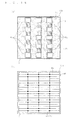
- FIG. 8(a) is a schematic view of the entire solar cell module 20C when seen from the first surface 1F side in plan view.
- the solar cell elements 10C configuring the solar cell module 20C are not the same as those shown in FIG.
- the portion A of the first connection part 4c of one solar cell element 10C and the second connection part 5a of the other solar cell element 10C exist on one straight line when the adjacent solar cell elements 10C are arranged so that the respective base sides BS are positioned on the same straight line and are in a translational symmetric relationship, as shown in FIG. 7(a) .
- the portion A of the first connection part 4c and the second connection part 5a satisfying such a relationship are connected using the wiring 11 having a linear shape in plan view.
- the relative arrangement relationship among the sets of the first connection part 4c and the second connection part 5a in a relationship of being connected with one wiring 11 is equivalent (i.e., all the sets of the first connection part 4c and the second connection part 5a are in a translational symmetric relationship), and thus the wiring 11 having the same shape can be used in the connection of each set of first connection part 4c and the second connection part 5a.
- the wiring having a shape similar to that used in the solar cell module 20A can be used, for example.
- the adjacent solar cell elements 10C' are arranged at a predetermined distance so that the respective base sides BS are positioned on the same straight line and so as to be in a translational symmetric relationship, as in the solar cell module 20C.
- the portion C of the first connection part 4c and all the second connection parts 5a positioned on the same straight line are connected with one wiring 11.
- the relative arrangement relationship among the sets of the first connection part 4c and the second connection part 5a in a relation of being connected with one wiring 11 is equivalent (i.e., all the sets of first connection part 4c and second connection part 5a are in a translational symmetric relationship), and thus the wiring 11 of the same shape can be used for the connection of each set of portion C of the first connection part 4c and the second connection part 5a.
- the wiring having a shape similar to that used in the solar cell module 20A can be used.
- the portion C and the second connection part 5a may be formed into a shape different from above (e.g., trapezoid, circle, ellipse, semicircle, fan-shape, or composite shape thereof) as long as the above array state is met and the connection mode by the wiring 11 can be realized.
- a shape different from above e.g., trapezoid, circle, ellipse, semicircle, fan-shape, or composite shape thereof
- FIG. 9 is a diagram illustrating a solar cell element 10C", which is another variation of the solar cell element 10C, and a solar cell module 20C" configured using a plurality of solar cell elements 10C" according to the present embodiment.
- FIG. 9(a) is a diagram of the solar cell element 10C" when seen from the second surface 1S side in plan view
- FIG. 9(b) is a diagram of two adjacent solar cell elements 10C" in the solar cell module 20C" when seen from the second surface 1S side in plan view.
- the solar cell element 10C" is similar to the solar cell element 10C in that the first connection part 4c has a bent shape, but differs from the solar cell element 10C in that the second connection part 5a also has a bent shape.
- a state in which the first connection part 4c of one solar cell element 10C" and the second connection part 5a of the other solar cell element 10C exist on one straight line is realized by arranging the adjacent solar cell elements 10C" so that the respective base sided BS are positioned on the same straight line and are in a translational symmetric relationship, as shown in FIG. 9(b) .
- the solar cell module 20C" is also similar to the solar cell module 20C in that the first connection part 4c and the second connection part 5a lined on one straight line are connected using a wiring 11 in a linear form in plan view.
- a solar cell element 10D and a solar cell element 10D', which is a variation thereof, according to a fourth embodiment, will be described with reference to FIG. 10 and FIG. 11 .
- FIG. 10 is a plan view of the solar cell element 10D and the solar cell element 10D' illustrating one example of electrode patterns of the first electrode 4 and the second electrode 5 in the solar cell element 10D and the solar cell element 10D'.
- FIG. 10(a) is a diagram illustrating the solar cell element 10D when seen from the second surface 1S side in plan view
- FIG. 10(b) is a diagram illustrating the solar cell element 10D when seen from the first surface side 1F in plan view
- FIG. 10(c) is a diagram illustrating the solar element 10D' when seen from the second surface 1S side in plan view
- FIG. 10(d) is a diagram illustrating the solar cell element 10D' when seen from the first surface 1F side in plan view.
- each first connection part 4c has an elongated shape (rectangle) parallel to the base side BS and is arranged at substantially regular intervals parallel to the reference direction.
- the second connection parts 5a of the same number as the first connection parts 4c are also arranged.
- Each second connection part 5a also has an elongated shape (rectangle) parallel to the base side BS and is arranged at substantially regular intervals parallel to the reference direction.
- the first connection parts 4c and the second connection parts 5a are alternately arranged.
- first connection parts 4c and the second connection parts 5a in the solar cell element 10D have the respective arrangement positions defined so that a rotational symmetrical arrangement is realized between adjacent solar cell elements 10D when configuring a solar cell module 20D, as will be described below.
- an elongated power collecting part 5b is formed at the peripheries of the second connection parts 5a.
- the non-formation region RE is ensured near both the ends of the first connection parts 4c. This aspect will be described below.
- both the plurality of first connection parts 4c and the plurality of second connection parts 5a are arranged at substantially regular intervals and discretely at positions where the first connection parts 4c and the second connection parts 5a are formed in the solar cell element 10D. That is, the solar cell element 10D' has a configuration in which the first connection parts 4c and the second connection parts 5a having an elongated shape in the solar cell element 10D are replaced with arrays of the plurality of (five in FIG. 10(c) ) first connection parts 4c and second connection parts 5a having smaller sizes than those in the solar cell element 10D in the longitudinal direction.
- the formation mode of the power collecting part 5b is similar to that in the solar cell element 10D.
- the through holes 3 are formed so as to substantially coincide with the formation positions of the first connection parts 4c in plan view, and the main electrode parts 4a are uniformly formed on the first surface 1F as a plurality of linear patterns connecting with the plurality of (four in FIGS. 10(b) and (d )) conductive parts 4b belonging to different arrays.
- FIG. 11 is a diagram illustrating the detail of connection of the solar cell elements 10D by the wirings 11 in the solar cell module 20D configured using the plurality of solar cell elements 10D.
- FIG. 11(a) is a diagram of two solar cell elements 10D adjacent to each other in the solar cell module 20D seen in plan view from the side of the second surface 1S.
- FIG. 11(b) is a diagram of the same in plan view seen from the side of the first surface 1F.
- FIG. 8(b) is a schematic view of the entire solar cell module 20D when seen from the first surface 1F side in plan view.
- the first connection part 4c of one solar cell element 10D and the second connection part 5a of the other solar cell element 10D exist on one straight line when the adjacent solar cell elements 10D are arranged so that the respective base sides BS are parallel and are at positions not on the same straight line, and are in a rotational symmetric (more specifically, point symmetric) relationship, as shown in FIG. 11(a) .
- point Q is the center of rotational symmetry.
- the first connection parts 4c and the second connection parts 5a satisfying such a relationship are connected using the wirings 11 in a linear form in plan view.
- the mutual relative arrangement relationship among the sets of the first connection part 4c and the second connection part 5a in a relationship of being connected with one wiring 11 is equivalent (i.e., the sets of the first connection part 4c and the second connection part 5a are all in a translational symmetric relationship), and thus the wiring 11 having the same shape can be used for the connection of each set of the first connection part 4c and the second connection part 5a.
- the wiring 11 having a shape similar to that used in the solar cell module 20A can be used, for example.
- the non-formation region RE is ensured near both the ends of the first connection parts 4c in the solar cell element 10D as described above in order to adapt to circumstances where there are two directions each solar cell element 10D may take in the solar cell module 20D and the connecting position by the wiring 11 differs according to the directions, namely, in order to use the solar cell elements 10D having the same electrode patterns regardless of the directions.
- the adjacent solar cells 10D' are arranged so that the respective base sides BS are parallel and are not at positions on the same straight line and so that they are in a rotational symmetric (specifically, point symmetric) relationship with each other, as in the solar cell module 20D. Accordingly, all the first connection parts 4c and all the second connection parts 5a positioned on the same straight line are connected by one wiring 11.
- the relative arrangement relationship among the sets of the plurality of first connection parts 4c and the plurality of second connection parts 5a in a relationship of being connected with one wiring 11 is equivalent (i.e., the sets of the plurality of first connection parts 4c and the plurality of second connection parts 5a are all in a translational symmetric relationship), and thus the wiring 11 having the same shape can be used for the connection of each set of the first connection part 4c and the second connection part 5a.
- the first connection parts 4c and the second connection parts 5a may be formed into a shape different from above (e.g., trapezoid, circle, ellipse, semicircle, fan-shape, or composite shape thereof) as long as the above array state is met and the connection mode by the wiring 11 can be realized.
- a shape different from above e.g., trapezoid, circle, ellipse, semicircle, fan-shape, or composite shape thereof
- the power collecting amount of the first connection parts 4c and the second connection parts 5a is smaller at the ends of the semiconductor substrate 1 than at the central part, and thus the formation widths in the short direction of the first connection parts 4c and the second connection parts 5a at the ends may be shorter than at the central part.
- the solar cell element 10E according to a fifth embodiment of the present invention will be described with reference to FIG. 12 and FIG. 13 .
- FIG. 12 is a plan view of the solar cell element 10E illustrating one example of electrode patterns of the first electrode 4 and the second electrode 5 in the solar cell element 10E.
- FIG. 12(a) is a diagram of the solar cell element 10E when seen from the second surface 1S side
- FIG. 12(b) is a diagram of the solar cell element 10E when seen from the first surface side in plan view.
- each first connection part 4c having a rectangular shape and having a longitudinal direction in the reference direction are divided into plural pieces into a plurality of columns (three columns in FIG. 12(a) ) and is arranged with a gap at substantially the regular intervals (five in FIG. 12(a) ).
- the columns are arranged at substantially equal intervals parallel to the reference direction.
- second connection parts 5a having a rectangular shape and having a longitudinal direction in the reference direction is arranged, with a gap at substantially the regular intervals, in a plurality of columns (i.e., the number of columns is the same as that of the columns of the first connection parts 4c) along the columns of the first connection parts 4c.
- first connection parts 4c and the second connection parts 5a are arranged to satisfy the relationship that there exists at least partially adjacent second connection part 5a for all the clearances between the first connection parts 4c.
- the second connection part 5a1 is adjacent to a part of the clearance s1
- the second connection part 5a2 is adjacent to the entire clearance s2.
- One elongated second connection part 5a can be arranged instead of being arranged in plurals. Furthermore, in the case of forming the high concentration doped layer 6 through the formation of the power collecting part 5b, a larger power collecting part 5b (high concentration doped layer 6) can be formed in the clearances between the second connection parts 5a by arranging a great number of second connection parts 5a, whereby the output characteristic of the solar cell element 10E can be enhanced.
- the arrangement positions of the first connection parts 4c and the second connection parts 5a are defined so that a rotational symmetric arrangement is realized between the adjacent solar cell elements 10E in the case of configuring a solar cell module 20E, as will be described below.
- the power collecting part 5b is formed over substantially the entire surface other than the formation region of the first connection parts 4c, as in the other embodiments.
- enlargement of the formation region of the power collecting part 5b and enlargement in the formation region of the high concentration doped layer 6 are achieved by two aspects in that both the first connection parts 4c and the second connection parts 5a are arranged up to the vicinity of the ends of the semiconductor substrate 1 in the arraying direction and the non-formation region RE is not ensured, and in that the power collecting part 5b is formed even at the clearance portions between the first connection parts 4c arranged in the same columns parallel to the base side BS.
- the carriers collected by the power collecting part 5b in the region on the side opposite to the columns of the second connection parts 5a with respect to the columns of the first connection parts 4c parallel to the base side BS can be satisfactorily retrieved from the second connection parts 5a.
- the power collection from the region F not formed with the second connection parts 5a is effectively carried out. That is, satisfactory power collecting efficiency can be obtained without arranging the second connection parts 5a in the region F.
- the through holes 3 are formed so as to substantially coincide with the formation positions of the first connection parts 4c in plan view in the solar cell element 10E.
- two through holes 3 are formed in correspondence to one first connection part 4c.
- the main electrode parts 4a are uniformly formed on the first surface 1F as a plurality of linear patterns connecting to all the conductive parts 4b.
- the main electrode parts 4a arranged perpendicular to the connecting direction of the wirings 11 may be arranged only at the portions where the clearances between the conductive parts 4b are large.
- FIG. 13 is a diagram illustrating the detail of connection by the wirings 11 of the solar cell elements 10E in the solar cell module 20E configured using a plurality of solar cell elements 10E.
- FIG. 13(a) is a diagram of two solar cell elements 10E adjacent to each other in the solar cell module 20E when seen from the second surface 1S side in plan view
- FIG. 13(b) is a diagram of the same when seen from the first surface 1F side in plan view.
- the adjacent solar cell elements 10E are arranged so that the respective base sides BS are parallel and are not positioned on the same straight line, and are in a rotational symmetric (specifically, point symmetric) relationship with each other, as shown in FIG. 13(a) , as in the solar cell module 20D.
- the first connection parts 4c of one solar cell element 10E and the second connection parts 5a of the other solar cell element 10E exist on one straight line.
- such first connection parts 4c and second connection parts 5a are connected using the wirings 11 having a linear form in plan view.
- the relative arrangement relationship among the sets of the first connection parts 4c and the second connection parts 5a in a relationship of being connected with one wiring 11 is equivalent (i.e., all the sets of the first connection parts 4c and the second connection parts 5a are in a translational symmetric relationship). Therefore, the connection of each set of the first connection part 4c and the second connection part 5a is performed by the wiring 11 having the same shape. For instance, the wiring having a shape similar to that used in the solar cell module 20A may be used.
- connection may be made using a wiring similar to a wiring 11B having a plurality of bent parts in cross-sectional view as will be described below.
- the first connection parts 4c and the second connection parts 5a may be formed into a shape different from above (e.g., trapezoid, circle, ellipse, semicircle, fan-shape, or composite shape thereof) as long as the above array state is met and the connection mode by the wiring 11 can be realized.
- a shape different from above e.g., trapezoid, circle, ellipse, semicircle, fan-shape, or composite shape thereof
- a solar cell element 10F according to a sixth embodiment of the present invention will be described with reference to FIG. 14 and FIG. 15 .
- FIG. 14 is a plan view of the solar cell element 10F illustrating one example of electrode patterns of the first electrode 4 and the second electrode 5 in the solar cell element 10F.
- FIG. 14(a) is a diagram of the solar cell element 10F when seen from the second surface 1S side in plan view
- FIG. 14(b) is a diagram of the solar cell element 10F when seen from the first surface 1F side in plan view.
- each plurality of (four in FIG. 14(a) ) first connection parts 4c having a rectangular shape and having a longitudinal direction in the reference direction is divided into a plurality of columns (six columns in FIG. 14(a) ) and is arranged with a gap at substantially the regular intervals.
- Each column is arranged at substantially the regular intervals parallel to the reference direction.
- connection parts 5a having a rectangular shape and having a longitudinal direction in the reference direction, similar to the first connection parts 4c, is arranged with a gap at substantially the regular intervals in a plurality of columns along the columns of the first connection parts 4c (i.e., the number of columns is the same as that of the columns of the first connection parts 4c).
- the columns of the first connection parts 4c and the columns of the second connection parts 5a configure a plurality of sets (three sets in FIG. 14(a) ) arranged alternately and adjacent to one another by a plurality of columns (two columns in FIG. 14(a) ).
- the columns of the first connection parts 4c are distinguished between a first column 4ca in which the column of the second connection parts 5a exists only on one side and a second column 4cb in which the column of the second connection parts 5a exists on both sides (sandwiched between the columns of the second connection parts 5a).
- the adjacent columns of the first connection parts 4c belonging to the same set are arranged such that the arrangement relationship between the first connection parts 4c and the clearances in the reference direction is reversed from each other between the adjacent columns.
- the adjacent columns of the second connection parts 5a belonging to the same set are arranged such that the arrangement relationship between the second connection parts 5a and the clearances in the reference direction is reversed from each other between the adjacent columns, and the second connection parts 5a are adjacent to the first connection parts 4c configuring the second column 4cb.
- the arrangement positions of the first connection parts 4c and the second connection parts 5a are defined so that a rotational symmetric arrangement is realized between the adjacent solar cell elements 10F in the case of configuring a solar cell module 20F, as will be described below.
- the power collecting part 5b is formed over substantially the entire surface other than the formation region of the first connection parts 4c, as in the other embodiments.
- the non-formation region RE is not prepared, and the power collecting part 5b is formed even in the clearance portions of the first connection parts 4c arranged in the same column. That is, enlargement of the formation region of the power collecting part 5b and enlargement in the formation region of the high concentration doped layer 6 are achieved.
- the through holes 3 are formed so as to substantially coincide with the formation positions of the first connection parts 4c in plan view in the solar cell element 10F.
- two through holes 3 are formed in correspondence to one first connection part 4c.
- the main electrode parts 4a are uniformly formed on the first surface 1F as a plurality of linear patterns connecting to the plurality of (three in FIG. 14(b) ) conductive parts 4b belonging to different arrays.
- FIG. 15 is a diagram illustrating the detail of connection by the wirings 11 of the solar cell elements 10F in the solar cell module 20F configured using a plurality of solar cell elements 10F.
- FIG. 15(a) is a diagram of two solar cell elements 10F adjacent to each other in the solar cell module 20F when seen from the second surface 1S side in plan view
- FIG. 15(b) is a diagram of the same when seen from the first surface 1F side in plan view.
- the adjacent solar cell elements 10F are arranged so that the respective base sides BS are parallel and are at positions not on the same straight line, and are in a rotational symmetric (specifically, point symmetric) relationship with each other, as shown in FIG. 15(a) , as in the solar cell module 20D.
- the first connection parts 4c of one solar cell element 10F and the second connection parts 5a of the other solar cell element 10F exist on one straight line.
- such first connection parts 4c and second connection parts 5a are connected using the wiring 11 having a linear form in plan view.
- the relative arrangement relationship among the sets of the first connection parts 4c and the second connection parts 5a in a relationship of being connected with one wiring 11 is equivalent (i.e., all the sets of the first connection parts 4c and the second connection parts 5a are in a translational symmetric relationship), and thus the connection of each set of the first connection part 4c and the second connection part 5a is performed by the wiring 11 having the same shape.
- a wiring having a shape similar to that used in the solar cell module 20A may be used.
- connection When the wirings 11 connected to the first connection parts 4c of the solar cell element 10F contacts the power collecting part 5b of the same solar cell element 10F, the first connection parts 4c and the power collecting part 5b short-circuit and leakage occurs, and thus, an insulating layer (not shown) is preferably formed on the power collecting part 5b at the locations that it might contact the wirings 11.
- the connection may be made using a wiring similar to the wiring 11B having a broken line shape in cross-sectional view as will be described below.
- the first connection parts 4c and the second connection parts 5a may be formed into a shape different from above (e.g., trapezoid, circle, ellipse, semicircle, fan-shape, or composite shape thereof) as long as the above array state is met and the connection mode by the wiring 11 can be realized.
- a solar cell element 10G according to a seventh embodiment of the present invention and a solar cell element 10G', which is a variation thereof, will be described with reference to FIG. 16 and FIG. 17 .
- FIG. 16 is a plan view of the solar cell element 10G and the solar cell element 10G' illustrating one example of electrode patterns of the first electrode 4 and the second electrode 5 in the solar cell element 10G and the solar cell element 10G'.
- FIG. 16(a) is a diagram of the solar cell element 10G when seen from the second surface 1S side in plan view
- FIG. 16(b) is a diagram of the solar cell element 10G when seen from the first surface 1F side in plan view
- FIG. 16(c) is a diagram of the solar cell element 10G' when seen from the second surface 1S side in plan view
- FIG. 16(d) is a diagram of the solar cell element 10G' when seen from the first surface 1F side in plan view.
- the shapes and the arrangement relationships of the first connection parts 4c and the second connection parts 5a in the solar cell element 10G and the solar cell element 10G' shown in FIGS. 16(a) and (c) are similar to the first connection parts 4c and the second connection parts 5a of the solar cell element 10D according to the fourth embodiment in that the longitudinal direction is in the reference direction and both the parts are arranged in parallel to the reference direction and alternately.
- the solar cell element 10G and the solar cell element 10G' differ from the solar cell element 10D in the relationship in the numbers of the first connection parts 4c and the second connection parts 5a.
- n (n is a natural number) pieces of first connection parts 4c and n-1 pieces second connection parts 5a are arranged in the solar cell element 10G.
- n n is a natural number
- n-1 pieces of first connection parts 4c and n pieces of second connection parts 5a are arranged in the solar cell element 10G'.
- the through holes 3 are formed so as to substantially coincide with the formation positions of the first connection parts 4c in plan view, and the main electrode parts 4a are uniformly formed on the first surface 1F as a plurality of linear patterns connecting to the plurality of (four in FIG. 16(b) , three in FIG. 16(d) ) conductive parts 4b belonging to different arrays both in the solar cell element 10G and the solar cell element 10G'.
- FIG. 17 is a diagram illustrating the detail of connection by the wirings 11 of the solar cell elements 10G and the solar cell elements 10G' in the solar cell module 20G configured using a plurality of solar cell elements 10G and a plurality of solar cell elements 10G'.
- FIG. 17(a) is a diagram of the solar cell element 10G and the solar cell element 10G' adjacent to each other in the solar cell module 20G when seen from the second surface 1S side in plan view
- FIG. 17(b) is a diagram of the same when seen from the first surface 1F side in plan view.
- the solar cell module 20G differs from the solar cell module according to each embodiment described above, and the solar cell element 10G and the solar cell element 10G' having different arrangement relationships between the first connection parts 4c and the second connection parts 5a are arranged alternately and so that the respective base sides BS are positioned on one straight line.
- the first connection parts 4c of a certain solar cell element 10G and the second connection parts 5a of the adjacently positioned solar cell element 10G' exist on one straight line.
- the first connection parts 4c and the second connection parts 5a satisfying such a relationship are connected using the wirings 11 (first wiring, second wiring) having a linear form in plan view.
- the relative arrangement relationship among the sets of the first connection part 4c and the second connection part 5a in a relationship of being connected with one wiring 11 is equivalent (i.e., all the sets of the first connection part 4c and the second connection part 5a are in a translational symmetric relationship), and thus the connection of each set of the first connection part 4c and the second connection part 5a is performed by the wiring 11 having the same shape.
- a wiring having a shape similar to that used in the solar cell module 20A may be used.
- a solar cell element 10H according to an eighth embodiment of the present invention will now be described with reference to FIG. 18 , FIG. 19 , and FIG. 20 .
- FIG. 18 is a plan view of the solar cell element 10H illustrating one example of electrode patterns of the first electrode 4 and the second electrode 5 in the solar cell element 10H.
- FIG. 18(a) is a diagram of the solar cell element 10H when seen from the second surface 1S side in plan view
- FIG. 18(b) is a diagram of the solar cell element 10H when seen from the first surface 1F side in plan view.
- each plurality of first connection parts 4c having a square shape is arranged discretely at substantially regular intervals in a plurality of columns (three columns in FIG. 18(a) ) parallel to the reference direction, and the second connection parts 5a are arranged between the first connection parts 4c in each column.
- five first connection parts 4c and four second connection parts 5a are arranged in one column.
- the columns are arranged at substantially regular intervals in parallel to the reference direction.
- the first connection parts 4c and the second connection parts 5a are formed into a size with which two wirings 11 can be arranged parallel to the reference direction when forming a solar cell module 20H to be described below.
- the power collecting part 5b is formed over substantially the entire surface other than the formation region of the first connection parts 4c. Since the second connection parts 5a are arranged while being sandwiched between the power collecting part 5b in the solar cell element 10H, the carriers collected at the power collecting part 5b are efficiently gathered at the second connection parts 5a.
- the through holes 3 are formed so as to substantially coincide with the formation positions of the first connection parts 4c in plan view.
- two through holes are formed in correspondence to one first connection part 4c.
- the main electrode parts 4a are uniformly formed on the first surface 1F as a plurality of linear patterns connecting to the plurality of (three in FIG. 18(b) ) conductive parts 4b belonging to different arrays.
- FIG. 19 is a diagram illustrating the detail of connection by the wirings 11 of the solar cell elements 10H in the solar cell module 20H configured using a plurality of solar cell elements 10H.
- FIG. 19(a) is a diagram of two solar cell elements 10H adjacent to each other in the solar cell module 20H when seen from the second surface 1S side in plan view
- FIG. 19(b) is a diagram of the same when seen from the first surface 1F side in plan view.
- the adjacent solar cell elements 10H are arranged so that the respective base sides BS are parallel and are positioned on the same straight line, and are in a translational symmetric relationship with each other, as shown in FIG. 19(a) , as in the solar cell module 20A, whereby the first connection parts 4c of one solar cell element 10H and the second connection parts 5a of the other solar cell element 10H exist on one straight line.
- the solar cell element 10H having the wirings 11 connected to the first connection parts 4c is referred to as a first solar cell element 10H ⁇
- the solar cell element 10H having the wirings connected to the second connection parts 5a is referred to as a second solar cell element 10H ⁇ , for the sake of convenience.
- the first connection parts 4c of the first solar cell element 10H ⁇ and the second connection parts 5a of the second solar cell element 10H ⁇ satisfying the above relationship are connected using the wirings 11 having a linear form in cross section, similar to that in the solar cell module 20A according to the first embodiment.
- the first connection parts 4c and the second connection parts 5a alternately arranged in one column in one solar cell element 10H are connected to the second connection parts 5a and the first connection parts 4c of a different solar cell element, respectively. That is, two wirings 11 are connected in parallel in that column.
- the first connection parts 4c and the second connection parts 5a are caused to short-circuit in the first solar cell element 10H ⁇ and the second solar cell element 10H ⁇ .
- an insulating layer (not shown) made of an oxide film, resin (an epoxy resin, an acrylic resin, a polyimide resin, a silicone resin, and the like), an insulating tape, and the like is arranged on the second connection parts 5a of the first solar cell element 10H ⁇ and the first connection parts 4c of the second solar cell element 10H ⁇ at a portion to be positioned immediately under the wirings 11, and then connecting with the wirings 11 is carried out.
- the insulating layer is formed only at half of the region in the first connection parts 4c and the second connection parts 5a. That is, as for the first connection parts 4c, the insulating layer is formed only in the region assumed as the first connection parts 4c of the second solar cell element 10H ⁇ , and as for the second connection parts 5a, the insulating layer is formed only in the region assumed as the second connection parts 5a of the first solar cell element 10H ⁇ .
- the relative arrangement relationship among the sets of the first connection parts 4c and the second connection parts 5a in a relationship of being connected with one wiring 11 is equivalent (i.e., the sets of first connection parts 4c and second connection parts 5a are all in a translational symmetric relationship), and thus the wiring 11 having the same shape can be used for the connection of each set of the first connection part 4c and the second connection part 5a.
- the formation of the insulating layer may be a mode of being performed by patterning through an application method or the like so as to be formed only at the relevant locations, or a mode of removing unnecessary portions after performing film formation with an insulating layer formation material on the second surface 1S side of the semiconductor substrate 1 after the first connection parts 4c, the second connection parts 5a, and the power collecting parts 5b are formed.
- FIG. 20(a) is a schematic view of a cross section parallel to the reference direction of the two solar cell elements 10H adjacent to each other in the solar cell module 20H to describe another connection mode in the solar cell module 20H.
- FIG. 20(b) is a perspective view illustrating a state of connection in such a connection mode.
- the first connection parts 4c of the first solar cell element 10H ⁇ and the second connection parts 5a of the second solar cell element 10H ⁇ are connected using wirings 11B having a plurality of bent parts in cross-sectional view, as shown in FIG. 20 .
- a wiring in which a copper film covered with solder similar to that used in the wiring 11 is folded in an appropriate shape is used for the wiring 11B.
- the wiring 11B has a plurality of first connection surfaces 11a connecting with the first connection parts 4c at the first solar cell element 10H ⁇ , a first separated part 11b between two first connection surfaces 11a, a plurality of second connection surfaces 11c connecting with the second connection parts 5a at the second solar cell element 10H ⁇ , and a second separated part 11d between two second connection surfaces 11c.
- the short circuit between the first connection parts 4c and the second connection parts 5a in one solar cell element 10H is reduced by having the gaps G1, G2 acting similarly to the insulating layer in the case of using the wiring 11 having a linear form in cross section as shown in FIG. 19 .
- a mode of arranging the insulating layer (not shown) for filling the gaps G1, G2 on the wiring 11B in advance, and connecting the wiring 11B may be adopted.
- the quality of alignment of the wiring 11B and the first connection parts 4c and the second connection parts 5a can be visibly checked. The reduction in connection failure can thereby be achieved.
- the first connection parts 4c and the second connection parts 5a may be formed into a shape different from above (e.g., trapezoid, circle, ellipse, semicircle, fan-shape, or composite shape thereof) as long as the above array state is met and the connection mode by the wiring 11 can be realized.
- a solar cell element 10I according to a ninth embodiment of the present invention will be described with reference to FIG. 21 and FIG. 22 .
- FIG. 21 is a plan view of the solar cell element 10I illustrating one example of electrode patterns of the first electrode 4 and the second electrode 5 in the solar cell element 10I.
- FIG. 21(a) is a diagram of the solar cell element l0I when seen from the second surface 1S side in plan view
- FIG. 21(b) is a diagram of the solar cell element 10H when seen from the first surface 1F side in plan view.
- each plurality of (five in the FIG. 21(a) ) first connection parts 4c having a rectangular shape and having a longitudinal direction in the reference direction is arranged with a gap at substantially regular intervals in a plurality of columns (three columns in FIG. 21(a) ), as in the solar cell element 10E according to the fifth embodiment.
- the columns are arranged at substantially regular intervals in parallel to the reference direction.
- second connection parts 5a having a rectangular shape and having a longitudinal direction in the reference direction is arranged with a gap formed at substantially regular intervals in a plurality of columns (i.e., the number of columns is the same as that of the columns of the first connection parts 4c) along the columns of the first connection parts 4c.
- the solar cell element 10I is the same as the solar cell element 10E of the fifth embodiment in that the arrangement positions of the first connection parts 4c and the second connection parts 5a are defined so that a rotational symmetric arrangement is realized between solar cell elements 10I adjacent to each other in the case a solar cell module 20I to be described below is configured with them.
- the solar cell element 10I is the same as the solar cell element 10E in that the first connection parts 4c and the second connection parts 5a are arranged so as to satisfy a relationship that there exits at least partially adjacent second connection part 5a for all the clearances between the first connection parts 4c, and the formation mode of the power collecting part 5b is also similar to the solar cell element 10E.
- the formation mode of the through holes 3 is also similar.
- the solar cell element 10I differs from the solar cell element 10E according to the fifth embodiment in three aspects that the solar cell element 10I has the columns of the first connection parts 4c and the columns of the second connection parts 5a spaced apart, that each first connection part 4c includes a region 4c1 where the wiring is arranged and a region 4c2 connected with the through hole and is formed into a convex shape in plan view having the latter region as a convex part, and that the through holes 3 are formed only immediately above the through hole arrangement regions 4c2 of the first connection parts 4c and not formed immediately above the wiring arrangement regions 4c1.
- FIG. 22 is a diagram illustrating the detail of connection by the wirings 11 between the solar cell elements 10I in the solar cell module 20I configured using a plurality of solar cell elements 10I having the above configuration.
- FIG. 22(a) is a diagram of two solar cell elements 10I adjacent to each other in the solar cell module 20I when seen from the second surface 1S side in plan view
- FIG. 22(b) is a diagram of the same when seen from the first surface 1F side in plan view.
- the adjacent solar cell elements 10E are arranged so that that the respective base sides BS are parallel and are positioned not on the same straight line, and are in a rotational symmetric (more specifically, point symmetric) relationship with each other, as shown in FIG. 22(a) , as in the solar cell module 20E.
- the first connection parts 4c of one solar cell element 10I and the second connection parts 5a of the other solar cell element 10I exist on one straight line.
- such first connection parts 4c and second connection parts 5a are connected using the wirings 11 having a linear form in plan view.
- the relative arrangement relationship among the sets of the first connection parts 4c and the second connection parts 5a in a relationship of being connected with one wiring 11 is equivalent (i.e., the sets of first connection parts 4c and second connection parts 5a are all in a translational symmetric relationship), and thus the wiring 11 having the same shape can be used for the connection of each set of the first connection part 4c and the second connection part 5a.
- a wiring having a similar shape to that used in the solar cell module 20A may be used.
- the wirings 11 are connected only at the wiring arrangement regions 4c1, as shown in FIG. 22 , and this realizes a structure in which the wirings 11 do not directly contact the through hole arrangement regions 4c2 formed with the conductive parts 4b immediately above.
- generation of heat contraction stress that may occur in the through holes 3 when connecting the wirings 11 to the first connection parts 4c using hot air, a soldering iron, or a reflow furnace can be alleviated.
- generation of cracks at the through holes 3 having a relatively weak strength can be reduced.
- the first connection parts 4c and the power collecting part 5b short-circuit and cause leakage, and thus an insulating layer is preferably formed on the power collecting part 5b at the locations that it contacts the wirings 11.
- a mode of connecting with wirings similar to the wirings 11B may be adopted.
- the wiring arrangement regions 4c1 and the through hole arrangement regions 4c2 of the first connection parts 4c and the second connection parts 5a may be formed into a shape different from above (e.g., trapezoid, circle, ellipse, semicircle, fan-shape, or composite shape thereof) as long as the above array state is met and the connection mode by the wirings 11 can be realized.
- a solar cell element 10J according to a tenth embodiment of the present invention will be described with reference to FIG. 23 .
- FIG. 23 is a plan view of the solar cell element 10J illustrating one example of electrode patterns of the first electrode 4 and the second electrode 5 in the solar cell element 10J when seen from the second surface 1S side in plan view.
- the shapes and the arrangement relationship of the first connection parts 4c and the second connection parts 5a are such that both of them have a longitudinal direction in the reference direction and are alternately arranged parallel to the reference direction. Furthermore, it is also similar that n-1 pieces of first connection parts 4c and n pieces of second connection parts 5a are arranged.
- the solar cell element 10J differs from the solar cell element 10G' in that each first connection part 4c of the solar cell element 10J has a concave-convex shape along the reference direction by alternately arranging two sites of different widths in the reference direction. Of the two sites, the site having a larger width is referred to as an adhering region 4c3, and the site having a smaller width is referred to as a non-adhering region 4c4.
- the solder of the wiring 11 is welded to connect the wiring 11 to the first connection part 4c only at the adhering regions 4c3 in the first connection part 4c. That is, adhesion is performed by points. It is more preferable that each wiring 11 is connected by being welded over the entire surface of the first connection part 4c, but sufficiently satisfactory connection is still realized with the mode of adhesion by points.
- the power collecting part 5b and the high concentration doped layer 6 can be formed wider, as shown in FIG. 23 , by arranging a non-adhering region 4c4 having a narrower width than the adhering region 4c3. That is, the first connection parts 4c are formed so as to have a concave-convex shape in the reference direction, and then the power collecting part 5b and the high concentration doped layer 6 are formed so as to have a concave-convex shape in the reference direction at the interface portions with the first connection parts 4c. The area of the formation region of the high concentration doped layer 6 then increases, and thus the output characteristics of the solar cell element is further enhanced.
- a solar cell element 10K according to an eleventh embodiment of the present invention and a solar cell element 10K', which is a variation thereof, will be described with reference to FIG. 24 and FIG. 25 .
- FIG. 24 is a plan view of the solar cell element 10K illustrating one example of electrode patterns of the first electrode 4 and the second electrode 5 in the solar cell element 10K.
- FIG. 24(a) is a diagram of the solar cell element 10K when seen from the second surface 1S side in plan view
- FIG. 24(b) is a diagram of the solar cell element 10K when seen from the first surface 1F side in plan view
- FIG. 24(c) is a diagram of the solar cell element 10K' when seen from the second surface 1S side in plan view.
- the solar cell element 10K has a structure that each plurality of (three in FIG. 24(a) ) square-shaped wiring arrangement regions 4c5 constituting portions of the first connection parts 4c is arranged discretely at substantially regular intervals in a plurality of columns (three columns in FIG. 24(a) ) in the reference direction, and that a plurality of second connection parts 5a is arranged so as to sandwich the respective wiring arrangement regions (first portions of first electrodes) 4c5 in each column.
- the solar cell element 10K seems to have a configuration similar to the solar cell element 10H according to the eighth embodiment (however, the position of the base sides BS of the solar cell element 10H shown in FIG. 18(a) is different by 90° from that of the solar cell element 10K shown in FIG. 24(a) ).
- the formation mode of the power collecting part 5b is also similar to the solar cell element 10H.
- the solar cell element 10K differs from the solar cell element 10H in that each wiring arrangement region 4c5 is continuous with the wiring arrangement region 4c5 of another column by a non-wiring arrangement region (second portion of first electrode) 4c6 extending in a direction perpendicular to the reference direction, that is, in that the first connection parts 4c have a longitudinal direction perpendicular to the reference direction and concave-convex shapes along the direction.
- the widths of the wiring arrangement region 4c5 and the non-wiring arrangement region 4c6 in the arrangement direction of a plurality of solar cell elements differ from each other, where the width of the wiring arrangement region 4c5 is greater than the width of the non-wiring arrangement region 4c6.
- the first connection parts 4c and the second connection parts 5a are formed into sizes with which two wirings 11 can be arranged parallel to the reference direction when forming a solar cell module 20K to be described below.
- a plurality of conductive parts 4b is formed in correspondence to a plurality of through holes 3 formed in the semiconductor substrate 1.
- the through holes 3 (conductive parts 4b) of the solar cell element 10K are formed so as to be positioned immediately above along the longitudinal direction (direction perpendicular to the reference direction) of the first connection parts 4c.
- the main electrode parts 4a are uniformly formed on the first surface 1F as a plurality of linear patterns connecting with a plurality of (three in FIG. 24(b) ) conductive parts 4b positioned in the reference direction.
- FIG. 25 is a diagram illustrating the detail of connection between the solar cell elements 10K or between the solar cell elements 10K' by the wirings 11 in the solar cell module 20K configured using a plurality of solar cell elements 10K and the solar cell module 20K' configured using a plurality of solar cell elements 10K'.
- FIG. 25(a) is a diagram of the two solar cell elements 10K adjacent to each other in the solar cell module 20K when seen from the second surface 1S side in plan view
- FIG. 25(b) is a diagram of the same when seen from the first surface 1F side in plan view
- FIG. 25(c) is a diagram of the two solar cell elements 10K' adjacent to each other in the solar cell module 20K' when seen from the second surface 1S side in plan view.
- the adjacent solar cell elements 10K are arranged so that the respective sides BS are positioned in parallel and on the same straight line, and in a translational symmetric relationship with each other, as shown in FIG. 24(a) , as in the solar cell module 20H, so that the first connection parts 4c of one solar cell element 10K and the second connection parts 5a of the other solar cell element 10K exist on one straight line.
- the first connection parts 4c and the second connection parts 5a are caused to short-circuit in one solar cell element 10K, as in the solar cell element 10H.
- an insulating layer (not shown) is arranged at sites where connection is not necessary, similar to the case of configuring the solar cell module 20H, and then connection by the wirings 11 is carried out when fabricating the solar cell element 10K or when configuring the solar cell module 20K.
- the solar cell elements 10K are connected so as to create a clearance corresponding to the insulating layer using the wirings 11B having a broken folded line shape.
- the solar cell elements 10K are connected so as to arrange the insulating layer in the clearance.
- the first connection parts 4c and the second connection parts 5a are not formed in a part corresponding to a region where the insulating layer is to be formed or a gap is to be created thereon of the first connection parts 4c and the second connections part 5a of the solar cell element 10K.
- the power collecting part 5b is formed in such part. That is, since the region of the power collecting part 5b is larger in the solar cell element 10K' than in the solar cell element 10K, the output characteristics in the solar cell element 10K' are further enhanced than in the solar cell element 10K.
- the first connection parts 4c and the second connection parts 5a in the solar cell element 10K' have the respective arrangement positions defined so as to realize a rotational symmetric arrangement between the adjacent solar cell elements 10K' when configuring the solar cell module 20K'.
- the adjacent solar cell elements 10K' are arranged so that the respective base sides BS are positioned in parallel and not on the same straight line, and so that they are in a rotational symmetric (more specifically, point symmetric) relationship, as shown in FIG. 25(c) . Accordingly, the first connection parts 4c of one solar cell element 10K' and the second connection parts 5a of the other solar cell element 10K' exist on one straight line.
- the first connection parts 4c and the second connection parts 5a are connected using the wirings 11 having a linear form in plan view.
- the wirings 11 connected to the first connection parts 4c of one solar cell element 10K' contact the power collecting part 5b of the same solar cell element 10K', the first connection parts 4c and the power collecting part 5b short-circuit and cause leakage, and thus an insulating layer (not shown) is preferably formed on the power collecting part 5b at locations where it contact the wirings 11.
- a wiring similar to the wiring 11B having a plurality of bent parts in cross-sectional view may be used.
- the relative arrangement relationship among the sets of the first connection parts 4c and the second connection parts 5a to be connected with one wiring 11 or wiring 11B is equivalent (i.e., all the sets of first connection parts 4c and second connection parts 5a are in a translational symmetric relationship), and thus a wiring having the same shape can be used for the wiring 11 or wiring 11B used in the connection of each set of the first connection part 4c and the second connection part 5a.
- the first connection parts 4c and the second connection parts 5a may be formed into a shape different from above (e.g., trapezoid, circle, ellipse, semicircle, fan-shape, or composite shape thereof) as long as the above array state is met and the connection mode by the wirings 11 can be realized.
- FIG. 26 is a diagram illustrating a various variations according to a structure in a cross-sectional direction of the solar cell element.
- FIG. 26(a) is a diagram illustrating a structure of the solar cell element in the case of extending the formation region of the high concentration doped layer 6 up to a position overlapping with the formation region of the first connection part 4c in plan view.
- This is realized through the procedures of forming the high concentration doped layer 6 so that it includes the portion overlapping with the location to be formed with the first connection part 4c (excluding the portion immediately below the through hole 3), then, forming an insulating layer 8a made of an oxide film such as silicon dioxide or a nitride film such as silicon nitride on the overlapped region of the high concentration doped layer 6 with the location to be formed with the first connection part 4c, and thereafter forming the first connection part 4c.
- the output characteristics of the solar cell element can be further enhanced compared to the embodiments described above.
- FIG. 26(b) is a diagram illustrating a structure of the solar cell element in the case where not only the high concentration doper layer 6 but also the power collecting part 5b has the formation region extended up to a position overlapping with the formation region of the first connection part 4c in plan view.
- This is realized by forming the high concentration doper layer 6 and the power collecting part 5b sequentially and so that they include the portion overlapping with the location to be formed with the first connection part 4c (excluding the portion immediately below the through hole 3), then, forming the insulating layer 8a so as to cover the overlapped region of the power collecting part 5b with the location to be formed with the first connection part 4c, and thereafter forming the first connection part 4c.
- an effect of reducing the movement distance of the carriers collected at the second connection part 5a and further enhancing the output characteristics of the solar cell element is obtained by adopting such a configuration.
- FIG. 26(c) is a diagram illustrating a structure of the solar cell element, as an application of the structure shown in FIG. 26(b) , in the case of arranging a plurality of first connection parts 4c that is not of band form (e.g., dot form) so as to form a column in the arrangement direction of the wiring 11 and moreover extending the high concentration doper layer 6 and the power collecting part 5b between the first connection parts 4c.
- the wiring 11 is arranged, other than at the connecting location with the first connection part 4c, on the insulating layer 8a such as an oxide film, resin, an insulating tape, formed on the power collecting part 5b.
- the insulating layer 8a such as an oxide film, resin, an insulating tape
- FIG. 27 is a diagram illustrating a variation of the arrangement of the power collecting part 5b at the portion that is also arranged at a region ensured as the non-formation region RE a region where the power collecting part 5b is not formed in the solar cell element of each embodiment described above.
- FIG. 27(a) is a plan view illustrating a variation of the solar cell element 10A according to the first embodiment shown in FIG. 2(a)
- FIG. 27(b) is a plan view illustrating a variation of the solar cell element 10C according to the third embodiment shown in FIG. 6(a)
- FIG. 27(c) is a plan view illustrating a variation of the solar cell element 10D according to the fourth embodiment shown in FIG. 10(a) .
- FIG. 27(a) to (c) are all diagrams when seen from the second surface 1S side of the semiconductor substrate 1 in plan view.
- FIG. 27(d) is a cross-sectional schematic view illustrating a cross section taken along Y-Y portion of the solar cell element shown in FIG. 27(a) .
- FIG. 28 is a diagram illustrating a solar cell module formed using the solar cell element according to the variation.
- FIG. 28(a) is a plan view of a solar cell module in the case where the solar cell element shown in FIG. 27(a) is used
- FIG. 28(b) is a plan view of a solar cell module in the case where the solar cell element shown in FIG. 27(b) is used
- FIG. 28(c) is a plan view of a solar cell module in the case where the solar cell element shown in FIG. 27(c) is used.
- FIGS. 28(a) to (c) are all diagrams seen from the second surface 1S side of the semiconductor substrate 1 in plan view.
- Each solar cell element shown in FIGS. 27(a) to (c) has an insulating layer 8b including an oxide film, resin, an insulating tape, and the like formed at the location corresponding to the non-formation region RE about the power collecting part 5b in the solar cell element having the structure acting as a basis in plan view. More specifically, as shown in FIG. 27(d) , the power collecting part 5b is extended at the relevant location, and the insulating layer 8b is arranged so as to cover the same. The power collecting efficiency of the carrier is thereby further enhanced.
- the insulating layer 8b may be formed by using a thin-film formation technique such as a CVD, may be formed by applying and firing an insulating paste such as a resin paste, or may be formed by attaching a commercially available insulating tape. When firing the insulating paste, the insulating paste can be fired and formed simultaneously with the electrode formation. Alternatively, the insulating layer 8b may be arranged in advance on the side of the wiring 11 instead on the side of the solar cell element, and connection may be made using the same.
- FIG. 29 and FIG. 30 are diagrams illustrating a variation of a configuration of the solar cell element that the adoption of it enhances the power collecting efficiency of the power collecting part 5b distant from the second connection part 5a in the solar cell element according to each embodiment described above.
- FIG. 29(a) is a plan view illustrating a variation of the solar cell element 10A according to the first embodiment shown in FIG. 2(a)
- FIG. 29(b) is a plan view illustrating a variation of the solar cell element 10C according to the third embodiment shown in FIG. 6(a)
- FIG. 30 is a plan view illustrating a variation of the solar cell element 10E according to the fifth embodiment shown in FIG. 12(a)
- FIG. 29 and FIG. 30 all show a diagram when seen from the second surface 1S side of the semiconductor substrate 1 in plan view.
- the solar cell element shown in FIG. 29 includes a finger part 5c connecting to the second connection part 5a and extending up to a region E of the second surface 1S where the second connection part 5a is not arranged in the way of going around to the outer periphery of the first connection part 4c.
- the finger part 5c is formed using a material having lower resistance than the power collecting part 5b.
- the carrier collected at the region E will be collected at the second connection part 5a with detouring around the first connection part 4c, when the finger part 5c is not arranged.
- the power collection from the region E can be more efficiently carried out by arranging the finger part 5c having smaller resistance than the power collecting part 5b along the movement path of the carrier.
- the finger part 5c can be formed using metal such as silver, copper, or the like as a main component.
- the finger part 5c can be formed at low cost.
- the second connection part 5a and the finger part 5c can be formed with different conductive pastes. For instance, silver paste may be used for the second connection part 5a, and copper paste may be used for the finger part 5c.
- the finger part 5c is arranged in the clearance between the first connection parts 4c.
- the carrier collected by the power collecting part 5b on the opposite side with respect to the adjacent first connection part 4c can be efficiently transmitted to the second connection part 5a.
- FIG. 31 is a cross-sectional schematic view of a solar cell element 50 formed with an insulating material layer 9 made of an oxide film, a nitride film, or the like instead of being formed with the second opposite conductivity type layer 2b and the third opposite conductivity type layer 2c. Specifically, a first insulating material layer 9a is formed on the surface of the through hole 3, and a second insulating material layer 9b made of an oxide film or a nitride film is formed on the second surface 1S of the semiconductor substrate 1.
- the leakage arising between the conductive part 4b and the semiconductor substrate 1 is reduced by forming the first insulating material layer 9a.
- the leakage arising between the semiconductor substrate 1 and the first connection part 4c is reduced by forming the second insulating material layer 9b.
- the surface recombination rate at the second surface 1S of the semiconductor substrate 1 lowers through passivation effect when an oxide film or a nitride film is formed as the second insulating material layer 9b, the output characteristics of the solar cell element is enhanced.
- the insulating material layer 9 can be formed by forming a silicon oxide film (SiO 2 film), a titanium oxide film (TiO 2 film), a silicon nitride film (SiNx), and the like to a thickness of about 10 ⁇ m to 50 ⁇ m using a sputtering method, a vapor deposition method, or a CVD method.
- the oxide film to be the insulating material layer 9 may be formed by performing thermal treatment on the semiconductor substrate 1 in a thermal oxidation furnace in an oxygen atmosphere or atmospheric atmosphere, or applying and firing an oxide film material using an application method such as spin coating, spraying, or screen printing.
- the insulating material layer 9 may be a single layer film, or may be a multi-layer including a double layer structure of a silicon dioxide film and a silicon nitride film.
- the passivation effect is further enhanced.
- the silicon nitride film formed using a plasma CVD method contains hydrogen (H 2 )
- diffusion of hydrogen (H 2 ) into the semiconductor substrate 1 by heating during film formation or after film formation, and bonding of the hydrogen (H 2 ) to dangling bond (remaining chemical bond) existing in the semiconductor substrate 1 reduce the possibility of the carrier being trapped by the dangling bond. Therefore, a solar cell element of higher efficiency can be obtained by forming a silicon nitride film over substantially the entire surface of the second surface 1S.
- the opposite conductivity type layer 2 is less likely to be formed on the back surface side of the semiconductor substrate 1 when forming the opposite conductivity type layer (diffusion layer).
- the electrode intensity can be enhanced compared to the case of forming the electrode on the semiconductor substrate 1, since the electrode contains a glass frit.
- the formation mode of the opposite conductivity type layer 2 is not limited to the above.
- an amorphous silicon hydride film, a crystalline silicon film including a micro crystalline silicon film, and the like may be formed using a thin-film formation technique.
- the thickness thereof is less than or equal to 50 nm and preferably lower than or equal to 20 nm; and in the case of forming using the crystalline silicon film, the thickness thereof is less than or equal to 500 nm and preferably lower than or equal to 200 nm.
- the i-type (non-dope) silicon region may be formed between the semiconductor substrate 1 and the opposite conductivity type layer 2 at a thickness of lower than or equal to 20 nm.
- the high concentration doped layer 6 may be formed with, e.g., an amorphous silicon hydride film and a crystalline silicon film including a microcrystalline silicon phase using a thin-film technique.
- the formation of the high concentration doped layer 6 is also preferably performed using the thin-film technique.
- the film thickness of the high concentration doped layer 6 is about 10 to 200 nm.
- the application and firing when forming the main electrode part 4a, the conductive part 4b, the first connection part 4c, the second connection part 5a, and the power collecting part 5b need not be performed in the order described in the embodiment above.
- the conductive paste for forming each part may all be applied and collectively fired to form all the electrodes.
- the main electrode part 4a may be applied/fired and formed after applying/firing and forming the power collecting part 5b, the second connection part 5a, the first connection part 4c, and the conductive part 4b.
- the procedures may be appropriately combined to form the same.
- the power collecting part 5b may be arranged immediately below the second connection part 5a.
- the insulating layer 8 When arranging the insulating layer 8 on the wiring 11, the insulating layer 8 may also be arranged at the position to be a clearance between the solar cell elements in the solar cell module. Furthermore, the aesthetic appearance can be improved by coloring the insulating layer 8 with a color similar to the back surface protective material 13 and the back side filler 15.
Landscapes
- Engineering & Computer Science (AREA)
- Life Sciences & Earth Sciences (AREA)
- Sustainable Development (AREA)
- Physics & Mathematics (AREA)
- Condensed Matter Physics & Semiconductors (AREA)
- Electromagnetism (AREA)
- General Physics & Mathematics (AREA)
- Computer Hardware Design (AREA)
- Microelectronics & Electronic Packaging (AREA)
- Power Engineering (AREA)
- Sustainable Energy (AREA)
- Photovoltaic Devices (AREA)
Abstract
Description
- The present invention relates to a solar cell module.
- A back contact type solar cell element is conventionally known as one type of solar cell element (refer to, for example, Japanese Laid-Open Patent Publication No.
63-211773 2002-500825 - The conventional solar cell element includes a semiconductor substrate exhibiting one conductivity type, a opposite conductivity type layer exhibiting a conductivity type opposite to the semiconductor substrate, a first electrode, and a second electrode having a polarity different from the first electrode. The semiconductor substrate has a plurality of through holes penetrating between a light receiving surface and a back surface. The opposite conductivity type layer includes a first opposite conductivity type layer arranged on the light receiving surface of the semiconductor substrate, second opposite conductivity type layers arranged on the surfaces of the through holes of the semiconductor substrate, and a third opposite conductivity type layer arranged on the back surface side of the semiconductor substrate. The first electrode includes a light receiving surface electrode part formed on the light receiving surface side of the semiconductor substrate, through hole electrode parts formed in the through holes, a bus bar electrode part formed at the ends of the back surface of the semiconductor substrate and a finger electrode part formed on the back surface of the semiconductor substrate. The light receiving surface electrode part, the through hole electrode parts, the finger electrode part, and the bus bar electrode part are electrically connected. The second electrode is formed at a portion of the back surface of the semiconductor substrate where the third opposite conductivity type layer is not formed.
- The conventional solar cell module has a configuration in which the bus bar electrodes of a plurality of solar cell elements, each having the above configuration, are connected by wiring.
- While wide spread use of the solar cell module using such a solar cell element is further being expected, it is essential to enhance the conversion efficiency of sunlight with a simple configuration. It is important to reduce the loss of photovoltaic power in enhancing the conversion efficiency.
- In view of the above problems, it is an object of the present invention to provide a highly efficient solar cell module with a simple configuration.
- A plurality of solar cell elements used in a solar cell module of the present invention include a power collecting part electrically connected to a connection part, and surrounding the connection part. When the adjacent solar cell elements are first solar cell element and second solar cell element among the plurality of solar cell elements, the wiring connected to the connection part of the first solar cell element and the connection part of the second solar cell element has a linear form in plan view.
- According to such a configuration, the solar cell module of the present invention is made to a solar cell module in which loss of photovoltaic power due to internal resistance is reduced and which has a simple configuration and high conversion efficiency.
-
-
FIG. 1 is a cross-sectional schematic view illustrating a structure of asolar cell element 10A according to a first embodiment of the present invention. -
FIG. 2 is a plan view of thesolar cell element 10A. -
FIG. 3 is a diagram schematically illustrating a configuration of thesolar cell module 20A according to the first embodiment of the present invention. -
FIG. 4 is a diagram illustrating in detail the state of connection of thesolar cell elements 10A bywirings 11 in thesolar cell module 20A. -
FIG. 5 is a plan view of a solar cell element 10B according to a second embodiment of the present invention. -
FIG. 6 is a plan view of asolar cell element 10C according to a third embodiment of the present invention and asolar cell element 10C' which is a variation thereof. -
FIG. 7 is a diagram illustrating in detail the state of connection of thesolar cell elements 10C by thewirings 11 in a solar cell module 20C according to the third embodiment of the present invention. -
FIG. 8 is a schematic view of the entire solar cell module 20C according to the third embodiment and asolar cell module 20D according to a fourth embodiment according to the present invention when seen from thefirst surface 1F side in plan view. -
FIG. 9 is a diagram illustrating asolar cell element 10C", which is a variation of thesolar cell element 10C, and a solar cell module 20C" configured using the plurality ofsolar cell elements 10C". -
FIG. 10 is a plan view of asolar cell element 10D and asolar cell element 10D' according to the fourth embodiment of the present invention. -
FIG. 11 is a diagram illustrating in detail the state of connection of thesolar cell elements 10D by thewirings 11 in thesolar cell module 20D according to the fourth embodiment. -
FIG. 12 is a plan view of asolar cell element 10E according to a fifth embodiment of the present invention. -
FIG. 13 is a diagram illustrating in detail the state of connection of thesolar cell elements 10E by thewirings 11 in asolar cell module 20E according to the fifth embodiment. -
FIG. 14 is a plan view of asolar cell element 10F according to a sixth embodiment of the present invention. -
FIG. 15 is a diagram illustrating in detail the state of connection of thesolar cell elements 10F by thewirings 11 in asolar cell module 20F according to the sixth embodiment. -
FIG. 16 is a plan view of asolar cell element 10G according to a seventh embodiment of the present invention and asolar cell element 10G' which is a variation thereof. -
FIG. 17 is a diagram illustrating in detail the state of connection of thesolar cell element 10G and thesolar cell element 10G' by thewirings 11 in the solar cell module 20G according to the seventh embodiment. -
FIG. 18 is a plan view of asolar cell element 10H according to an eighth embodiment of the present invention. -
FIG. 19 is a diagram illustrating in detail the state of connection of thesolar cell elements 10H by thewirings 11 in thesolar cell module 20H according to the eighth embodiment. -
FIG. 20 is a diagram illustrating a different connection mode between thesolar cell elements 10H in thesolar cell module 20H according to the eighth embodiment. -
FIG. 21 is a plan view of a solar cell element 10I according to a ninth embodiment of the present invention. -
FIG. 22 is a diagram illustrating in detail the state of connection of the solar cell elements 10I by thewirings 11 in the solar cell module 20I according to the ninth embodiment. -
FIG. 23 is a plan view of asolar cell element 10J according to a tenth embodiment of the present invention. -
FIG. 24 is a plan view of asolar cell element 10K according to an eleventh embodiment of the present invention. -
FIG. 25 is a diagram illustrating in detail the state of connection of thesolar cell elements 10K by thewirings 11 in thesolar cell module 20K according to the eleventh embodiment. -
FIG. 26 is a diagram illustrating various variations according to a structure in a cross sectional direction of the solar cell element. -
FIG. 27 is a diagram illustrating another variations of the solar cell element. -
FIG. 28 is a diagram illustrating a solar cell module formed using the solar cell element according to the variation shown inFIG. 28 . -
FIG. 29 is a diagram illustrating solar cell elements having finger parts. -
FIG. 30 is a diagram illustrating a solar cell element having a finger part. -
FIG. 31 is a cross-sectional schematic view of asolar cell element 50 formed with aninsulating material layer 9 instead of being formed with a second oppositeconductivity type layer 2b and a third oppositeconductivity type layer 2c. - Preferred embodiments of a solar cell module of the present invention will be described in detail with reference to the drawings.
-
FIG. 1 is a cross-sectional schematic view illustrating a configuration of asolar cell element 10A according to a first embodiment of the present invention. - The
solar cell element 10A includes asemiconductor substrate 1 of one conductivity type, a oppositeconductivity type layer 2 of a conductivity type different from thesemiconductor substrate 1, afirst electrode 4, and asecond electrode 5. - The
solar cell element 10A includes thesemiconductor substrate 1 with afirst surface 1F (upper surface side inFIG. 1 ), and asecond surface 1S (lower surface side inFIG. 1 ) on the back side of thefirst surface 1F. In thesolar cell element 10A, thefirst surface 1F serves as a light receiving surface (for the sake of convenience of description, thefirst surface 1F is sometimes referred to as a light receiving surface or the like of the semiconductor substrate 1). - A crystalline silicon substrate such as a single crystalline silicon substrate and (or) a polycrystalline silicon substrate having a predetermined dopant element (impurities for conductivity type control) and exhibiting one conductivity type (e.g., p-type) is used as the
semiconductor substrate 1. A mode of using a plate-shaped silicon obtained through a pulling method such as a ribbon method may be adopted. The thickness of thesemiconductor substrate 1 is preferably less than or equal to 300 µm, more preferably less than or equal to 250 µm, and even more preferably less than or equal to 150 µm. - In the present embodiment, a case where a crystalline silicon substrate exhibiting a p-type conductivity type is used as the
semiconductor substrate 1 will be described by way of example. When thesemiconductor substrate 1 made of a crystalline silicon substrate exhibits p-type, boron or gallium is one suitable example for the dopant element. In particular, when gallium is used, the light deterioration phenomenon can be reduced, and higher efficiency of the solar cell element can be achieved. - A texture structure (uneven structure) 1a with a great number of
microscopic projections 1b are formed on the side of thefirst surface 1F of thesemiconductor substrate 1 to reduce the reflection of the incident light at thefirst surface 1F and absorb more sunlight into thesemiconductor substrate 1. Theprojections 1b suitably have a width and a height of less than or equal to 2 µm, and an aspect ratio (height/width) of greater than or equal to 0.1 and less than or equal to 2. Thetexture structure 1a is formed through methods such as wet etching and dry etching. Thetexture structure 1a is not an essential configuration in the present embodiment, and may be formed as necessary. - A plurality of through
holes 3 is formed between thefirst surface 1F and thesecond surface 1S in thesemiconductor substrate 1. InFIG. 1 , the cross section including only one throughhole 3 is illustrated for the sake of convenience of illustration. As hereinafter described, the throughhole 3 has a second oppositeconductivity type layer 2b formed on the surface. Aconductive part 4b of thefirst electrode 4 is formed inside the throughhole 3. The throughholes 3 are preferably formed at a constant pitch with a diameter in the range of greater than or equal to 50 µm and less than or equal to 300 µm. The diameters of the throughhole 3 may differ between thefirst surface 1F and thesecond surface 1S. The throughholes 3 are formed with a mechanical drill, a water jet, a laser processing device, or the like. - The opposite
conductivity type layer 2 is a layer that exhibits a conductivity type opposite to thesemiconductor substrate 1. The oppositeconductivity type layer 2 includes a first oppositeconductivity type layer 2a formed on thefirst surface 1F side of thesemiconductor substrate 1, a second oppositeconductivity type layer 2b formed on the surface of the throughhole 3, and a third oppositeconductivity type layer 2c formed on thesecond surface 1S side of thesemiconductor substrate 1. When a silicon substrate exhibiting a conductivity type of p-type is used for thesemiconductor substrate 1, the oppositeconductivity type layer 2 is formed to exhibit the conductivity type of n-type. This is realized by diffusing phosphorous (P) through thermal diffusion method or the like. The method of forming the oppositeconductivity type layer 2 will be described below in detail. - The first opposite
conductivity type layer 2a is suitably formed as n+-type having sheet resistance of about 60 to 300Ω/□. With such a range, increase in surface recombination and increase in surface resistance at thefirst surface 1F can be suppressed. In particular, in a case where the first oppositeconductivity type layer 2a is arranged in combination with thetexture structure 1a, short-circuit current of thesolar cell element 10A is greatly increased. The value of the sheet resistance can be measured through a four-probe method. For instance, four metal needles lined on a straight line are contacted to the surface of thesemiconductor substrate 1 while applying pressure, current is flowed to two needles on the outer side, and the voltage generated between two needles on the inner side is measured, whereby the resistance value is obtained from that voltage and the flowed current by the Ohm's law. - The first opposite
conductivity type layer 2a is preferably formed to a depth of about 0.2 µm to 0.5 µm at the region other than the portion formed with the throughhole 3 in thefirst surface 1F of thesemiconductor substrate 1. The third oppositeconductivity type layer 2c merely needs to be formed at the peripheral part of the throughhole 3 in thesecond surface 1S of thesemiconductor substrate 1. - A pn junction is formed between the opposite
conductivity type layer 2 and the bulk region of the semiconductor substrate 1 (region other than the opposite conductivity type layer 2) in thesolar cell element 10A by including the oppositeconductivity type layer 2. - The
solar cell element 10A includes a high concentration dopedlayer 6 inside thesemiconductor substrate 1. The high concentration dopedlayer 6 is a layer arranged with the aim of generating an internal electric field inside thesolar cell element 10A (with the aim of achieving a so-called BSF effect) to prevent lowering of power generation efficiency caused by occurrence of carrier recombination in the vicinity of thesecond surface 1S of thesemiconductor substrate 1. The high concentration dopedlayer 6 is formed over substantially the entire surface other than the vicinity of the throughhole 3 on the side of thesecond surface 1S of thesemiconductor substrate 1. More specifically, the high concentration dopedlayer 6 is formed so as not to contact the third oppositeconductivity type layer 2c (so that the bulk region of thesemiconductor substrate 1 exists in between) on the side of thesecond surface 1S. The specific formation pattern differs according to the formation pattern of thefirst electrode 4. - "High concentration" herein means that a dopant element exists at a concentration higher than the concentration of the dopant element that is doped to exhibit one conductivity type in the
semiconductor substrate 1. The high concentration dopedlayer 6 is suitably formed, e.g., by diffusing a dopant element such as boron or aluminum from thesecond surface 1S so that the concentration of the dopant element becomes about 1 × 10¹⁸ to 5 × 10²¹ atoms/cm3. The high concentration dopedlayer 6 thereby exhibits a conductivity type of p+-type and realizes ohmic contact with apower collecting part 5b to be described below. - When boron is the dopant element, the high concentration doped
layer 6 can be formed using thermal diffusion method with BBr3 (boron tribromide) as a diffusion source. When aluminum is the dopant element, the high concentration dopedlayer 6 can be formed by applying and firing aluminum paste containing aluminum powder, organic vehicle, and the like. - The high concentration doped
layer 6 is preferably formed to greater than or equal to 70% and less than or equal to 90% of the entire region of thesecond surface 1S when thesecond surface 1S of thesemiconductor substrate 1 is seen in plan view. In the case of greater than or equal to 70%, the BSF effect for enhancing the output characteristics of thesolar cell element 10A is obtained. The concentration is made to lower than or equal to 90% since it is necessary to ensure the region for forming afirst connection part 4c of thefirst electrode 4 and a non-formation region RE (described below) of thepower collecting part 5b that becomes necessary with the formation of thefirst connection part 4c. In thesolar cell element 10A of the present invention, however, the formation region of thefirst connection part 4c can be made smaller than in the conventional solar cell element as will be described below, and thus the high concentration dopedlayer 6 can be formed in a sufficiently large range of at a maximum of 90% of the entire region when thesecond surface 1S is seen in plan view. - The
solar cell element 10A includes anantireflection coating 7 on thefirst surface 1F side of thesemiconductor substrate 1. Theantireflection coating 7 serves to reduce the reflection of the incident light at the surface of thesemiconductor substrate 1 and is formed on the first oppositeconductivity type layer 2a. Theantireflection coating 7 is suitably formed with a silicon nitride film (SiNx film (composition ratio (x) ranges with Si3N4 stoichiometry as the center)), oxide material film (TiO2 film, SiO2 film, MgO film, ITO film, SnO2 film, ZnO film), or the like. The suitable value for the thickness of theantireflection coating 7 differs depending on the constituting material, but is set to a value that realizes nonreflecting condition with respect to the incident light. For instance, when a silicon substrate is used for thesemiconductor substrate 1, theantireflection coating 7 is formed with a material having an index of refraction of about 1.8 to 2.3 to a thickness of about 500 to 1200 Å. The arrangement of theantireflection coating 7 is not essential in the present embodiment and may be formed as necessary. Theantireflection coating 7 is formed through PECVD method, vacuum deposition method, sputtering method, and the like. - The
first electrode 4 is configured by amain electrode part 4a formed on thefirst surface 1F of thesemiconductor substrate 1, afirst connection part 4c formed on thesecond surface 1S, and aconductive part 4b arranged in the throughhole 3 for electrically connecting themain electrode part 4a with thefirst connection part 4c. Themain electrode part 4a has a function of collecting carriers generated at thefirst surface 1F, and thefirst connection part 4c serves as a wiring connection part for connecting external wirings. Themain electrode part 4a, theconductive part 4b, and thefirst connection part 4c are formed by applying conductive paste containing metallic powder on thefirst surface 1F (for themain electrode part 4a and theconductive part 4b) or thesecond surface 1S (for thefirst connection part 4c) of thesemiconductor substrate 1 in a predetermined electrode pattern, and then firing the same. - On the other hand, the
second electrode 5 has a polarity different from thefirst electrode 4 and is configured by a second connection part (bus bar part) 5a and apower collecting part 5b surrounding thesecond connection part 5a. Thepower collecting part 5b is formed on the high concentration dopedlayer 6 formed on the side of thesecond surface 1S of thesemiconductor substrate 1 and collects carriers generated on the side of thesecond surface 1S. Thesecond connection part 5a serves as a wiring connection part for connecting external wirings. When forming both the parts, at least part of thesecond connection part 5a is preferably configured to overlap with thepower collecting part 5b. - The
power collecting part 5b is formed, e.g., by applying conductive paste containing aluminum and silver as the metallic powder on the high concentration dopedlayer 6 in a predetermined electrode pattern, and then firing the same. When aluminum paste is used for the conductive paste, the high concentration dopedlayer 6 and thepower collecting part 5b can be simultaneously formed, as will be described below. - The
second connection part 5a is formed by applying conductive paste containing silver as a main component as the metallic powder on the high concentration dopedlayer 6 in a predetermined electrode pattern, and then firing the same. Thesecond connection part 5a is thereby electrically connected to thepower collecting part 5b. - When silver is used for the
second connection part 5a, and aluminum is used for thepower collecting part 5b, thesecond connection part 5a preferably contains zinc or a zinc alloy. According to such a configuration, the rise in resistance between thepower collecting part 5b and thesecond connection part 5a can be reduced. In particular, in the case of being formed to contain zinc or a zinc alloy at greater than or equal to 7 parts by weight and lower than or equal to 35 parts by weight with respect to silver of 100 parts by weight, the output characteristics of thesolar cell element 10A further less likely to lower. - According to such a configuration, there is realized a
solar cell element 10A having n+/p/p+ junction of the oppositeconductivity type layer 2, thesemiconductor substrate 1, and the high concentration dopedlayer 6 between thefirst electrode 4 and thesecond electrode 5. -
FIG. 2 is a plan view of thesolar cell element 10A illustrating one example of the electrode patterns of thefirst electrode 4 and thesecond electrode 5.FIG. 2(a) is a diagram of thesolar cell element 10A seen from the side of thesecond surface 1S in plan view (also referred to as a back surface view), andFIG. 2(b) is a diagram of thesolar cell element 10A seen from the side of thefirst surface 1F in plan view (also referred to as a light receiving surface view). To facilitate the understanding on the relationship between the electrode pattern arranged on the side of thefirst surface 1F and the electrode pattern arranged on the side of thesecond surface 1S, the electrode patterns in a relationship where the front and back surfaces of thesolar cell element 10A are actually inverted is not shown inFIG. 2(a) and FIG. 2(b) , and illustration is made such that the electrode pattern on the back surface side in the case where thesolar cell element 10A is virtually seen through from the light receiving surface side shown inFIG. 2(b) has a relationship corresponding to the electrode pattern shown inFIG. 2(a) . Although not mentioned, this holds true for the subsequent figures in a similar relationship. - As shown in
FIG. 2(b) , a plurality ofconductive parts 4b is formed in thesolar cell element 10A in correspondence to the plurality of throughholes 3 formed in thesemiconductor substrate 1. That is, the formation positions of theconductive parts 4b shown in black dots inFIG. 2(b) correspond to the formation positions of the through holes 3. In the present embodiment, there is shown a case where the plurality of throughholes 3 is formed so that an array of a plurality of columns (three columns inFIG. 2(b) ) is formed parallel to a direction (direction inclined by an inclination angle θ with respect to a base side BS of thefirst surface 1F of the semiconductor substrate 1) shown with an arrow AR1 inFIG. 2(b) , and theconductive part 4b is formed inside each of the plurality of throughholes 3. The base side BS is the side parallel to the arraying direction in the case of arraying the plurality ofsolar cell elements 10A whereby to form thesolar cell module 20A. The direction along the base side BS (direction parallel to the base side BS) is referred to as a reference direction. InFIG. 2(b) , the throughholes 3 are arranged so as to be arrayed in a plurality of (three inFIG. 2 ) straight lines, and thesolar cell element 10A includes the through holes 3 (conductive parts 4b) formed at substantially equal intervals. - It is to be noted that the term "parallel" in the present description should not be strictly defined as in a mathematical definition.
- Furthermore, the
main electrode parts 4a are formed on thefirst surface 1F as a plurality of linear patterns connecting with the plurality of (three inFIG. 2(b) )conductive parts 4b belonging to different arrays. Suchmain electrode parts 4a are suitably formed to have a line width of about 50 to 100 µm. Thus, when light is evenly emitted onto thefirst surface 1F, concentrating of the current flow at oneconductive part 4b, and increase in the resistance loss is reduced. The output characteristics of the solar cell element are thus less likely to lower. The pattern of themain electrode parts 4a is not limited to that shown inFIG. 2(b) , and various patterns can be formed (this holds true for the subsequent embodiments). - In addition, in the
solar cell element 10A, high light receiving efficiency is realized since the occupying proportion of themain electrode parts 4a configuring thefirst electrode 4 is very small compared to the entire surface of thefirst surface 1F, or the light receiving surface, and the carriers generated at thefirst surface 1F can be efficiently collected since themain electrode parts 4a are uniformly formed. - Meanwhile, as shown in
FIG. 2(a) , thefirst connection parts 4c having an elongated shape (parallelogram) with a longitudinal direction in the arraying direction of theconductive parts 4b (i.e. having a band form), and being connected to theconductive parts 4b are formed at positions immediately below the plurality ofconductive parts 4b (through holes 3) at thesecond surface 1S of thesemiconductor substrate 1. Thefirst connection parts 4c are formed in plural (three inFIG. 2(a) ) in correspondence to the array of theconductive parts 4b. - The
power collecting part 5b is formed over substantially the entire surface of thesecond surface 1S excluding thefirst connection parts 4c, the peripheral portion of thefirst connection parts 4c, and thesecond connection parts 5a of thesecond electrodes 5. "Substantially the entire surface" herein refers to the case where thepower collecting part 5b is formed at greater than or equal to 70% and less than or equal to 90% of the entire region of thesecond surface 1S when thesecond surface 1S of thesemiconductor substrate 1 is seen in plan view. The region near the edge surfaces of thesemiconductor substrate 1 of thesolar cell element 10A that is not formed with thefirst connection parts 4c but is to be covered by awiring 11 during the formation of thesolar cell module 20A, as will be described below, is assumed as a non-formation region RE where thepower collecting part 5b is not formed to prevent thewiring 11 from contacting thepower collecting part 5b whereby to reduce the occurrence of leakage. The arrangement of thepower collecting part 5b over substantially the entire surface other than the region formed with thefirst connection parts 4c and the non-formation region RE shortens the movement distances of the carriers collected at thepower collecting part 5b and increases the amount of carriers to be retrieved from thesecond connection parts 5a, and thus contributes to enhancement of the output characteristics of thesolar cell element 10A. - Furthermore, the
second connection parts 5a are arranged so that at least parts thereof overlap with thepower collecting part 5b. The plurality ofsecond connection parts 5a (three in correspondence to thefirst connection parts 4c inFIG. 2(a) ), has an elongated shape (parallelogram) similar to thefirst connection parts 4c (i.e., having a band form) in a mode of being parallel to each of the plurality offirst connection parts 4c. The formation position of eachsecond connection part 5a (in particular, formation interval with the adjacentfirst connection part 4c) is defined according to the arrangement interval of the adjacentsolar cell elements 10A in the case where the plurality ofsolar cell elements 10A is arranged adjacent to each other (in the case of configuring a solar cell module). This will be described below. - The
solar cell element 10A according to the present embodiment can be used alone, but a suitable structure is obtained by adjacently arranging a plurality ofsolar cell elements 10A having the same structure and connecting the same in series to one another to configure a module. The solar cell module formed using the plurality ofsolar cell elements 10A will be described below. -
FIG. 3 is a diagram schematically illustrating a configuration of such asolar cell module 20A.FIG. 3(a) is a cross-sectional view of thesolar cell module 20A, andFIG. 3(b) is a front view of thesolar cell module 20A seen from the light receiving surface side. - As shown in
FIG. 3(a) , thesolar cell module 20A mainly includes atranslucent member 12 made of glass and the like, asurface side filler 24 made of transparent ethylene-vinyl acetate copolymer (EVA) and the like, the plurality ofsolar cell elements 10A, aback side filler 15 made of EVA and the like, and a back surfaceprotective member 13 having polyethylene telephthalate (PET) or a metal foil sandwiched with polyvinyl fluoride resin (PVF) and the like. The plurality ofsolar cell elements 10A has the adjacentsolar cell elements 10A connected in series to each other with thewirings 11 serving as a connection member. -
FIG. 4 is a diagram illustrating the detail of connection of thesolar cell elements 10A by thewirings 11 in thesolar cell module 20A.FIG. 4(a) is a diagram of twosolar cell elements 10A adjacent to each other in thesolar cell module 20A seen in plan view from the side of thesecond surface 1S.FIG. 4(b) is a diagram of the same in plan view seen from the side of thefirst surface 1F. -
FIG. 3 only shows schematic cross sections, but onefirst connection part 4c of one of the adjacentsolar cell elements 10A and onesecond connection part 5a of the othersolar cell element 10A are connected by an elongated (linear)wiring 11 in thesolar cell module 20A, as shown inFIG. 4(a) . In the case ofFIG. 4 , connection is made at three locations. In the following description, of the twosolar cell elements 10A connected by thewirings 11 inFIG. 4 , thesolar cell element 10A having thewiring 11 connected to thefirst connection part 4c is referred to as a first solar cell element 10Aα, and thesolar cell element 10A having the wiring connected to thesecond connection part 5a is referred to as a second solar cell element 10Aβ, for the sake of convenience. - More specifically, in the
solar cell module 20A, the first solar cell element 10Aα and the second solar cell element 10Aβ are arranged such that the respective base sides BS are positioned on the same straight line and so that the longitudinal directions of thefirst connection parts 4c of the first solar cell element 10Aα and the longitudinal directions of the correspondingsecond connection parts 5a of the second solar cell element 10Aαβ are positioned on substantially the same straight line. The first solar cell element 10Aα and the second solar cell element 10Aβ are connected by thelinear wirings 11 in plan view on substantially the same straight line. This is because the arrangement mode of thefirst connection parts 4c and thesecond connection parts 5a (e.g., inclination angle θ, spacing between thefirst connection part 4c and thesecond connection part 5a, and the like) is defined so that thefirst connection parts 4c of the first solar cell element 10Aα and thesecond connection parts 5a of the second solar cell element 10Aβ satisfy the above positional relationship in the case where thesolar cell elements 10A are adjacently arranged at a predetermined distance w. In other words, thefirst connection parts 4c and thesecond connection parts 5a are arranged so that the first solar cell element 10Aα and the second solar cell element 10Aβ are electrically connectable with the plurality ofwirings 11 in the case where the first solar cell element 10Aα and the second solar cell element 10Aβ are arranged at a distance w so as to be translational symmetric to each other. - The inclination angle θ is preferably greater than or equal to 0.3 degrees and less than or equal to 15 degrees if a
semiconductor substrate 1 of 15 cm squares is used. When the size of one side of thesemiconductor substrate 1 is greater than or equal to 15 cm, a smaller value may be adopted. In this case, since it can be seen as if thewirings 11 are formed substantially perpendicular to one side of therectangular semiconductor substrate 1, a beautiful appearance is obtained. - In the
solar cell module 20A, the relative arrangement relationship among the sets of thefirst connection part 4c and thesecond connection part 5a in a relationship of being connected with onewiring 11 is equivalent (i.e., sets offirst connection part 4c andsecond connection part 5a are all in translational symmetric relationship) excluding thesolar cell element 10A arranged at the ends, and thus thewiring 11 having the same shape can be used for the connection of the each set of thefirst connection part 4c and thesecond connection part 5a. - A wiring, e.g., having a thickness of about 0.1 to 0.4 mm and a width of about 2 mm, and having a band shaped copper foil with the entire surface covered by a solder material cut into a predetermined length in the longitudinal direction can be used for the
wiring 11. In the case of thewiring 11 covered with a solder material, it is soldered to thefirst connection part 4c and thesecond connection part 5a of thesolar cell element 10A using hot air or a soldering iron, or using a reflow furnace and the like. - In the
solar cell module 20A connected with thewirings 11 in such a mode, the plurality offirst connection parts 4c is individually and directly connected to thesecond connection parts 5a of the adjacent solar cell elements, as opposed to the conventional solar cell module in which connection by one wiring is carried out at the bus bar part arranged at the end of the solar cell element, and thus a path of a collecting current from eachmain electrode part 4a is shortened. Thus, the loss of photovoltaic power due to the internal resistance is less likely to occur than in the conventional solar cell module. - The
wiring 11 merely needs to be connected to one portion of each of thefirst connection part 4c and thesecond connection part 5a as long as the connection therebetween is sufficiently obtained (resistance is sufficiently small), and need not necessarily be arranged so as to cover the entirefirst connection part 4c and thesecond connection part 5a. Regarding the connection of thefirst connection part 4c and thewiring 11, thewiring 11 is arranged so that thewiring 11 exists at the portion immediately below the through hole 3 (conductive part 4b). Since thewiring 11 also exists as the conductive member in addition to thefirst connection part 4c immediately below the throughhole 3 where thewiring 11 is arranged, and thus the cross sectional area of the conductive portion becomes larger. Thus, the reduction in the conduction resistance in retrieving the collecting current is realized. - An effect of facilitating the positioning of the
wirings 11 in connection is obtained by arranging thefirst connection parts 4c of the first solar cell element 10Aα and thesecond connection parts 5a of the second solar cell element 10Aβ on the same straight lines. That is, there is obtained an effect that the connection step of thesolar cell element 10A and thewirings 11 is less likely to become complicated. - Furthermore, in the
solar cell module 20A according to the present embodiment, thewirings 11 are arranged connecting only with thefirst connection parts 4c and thesecond connection parts 5a arranged on the side of thesecond surface 1S of thesolar cell element 10A, and thus thewirings 11 need not be bent to be connected on thefirst surface 1F side as in the conventional solar cell module. Accordingly, the wirings are less likely to be stripped from the electrodes. - In addition, the
solar cell elements 10A are connected only at thesecond surface 1S side, and thus the region thewirings 11 that have glaze due to the metal raw material is relatively small when the solar cell module is seen from thefirst surface 1F side or the light receiving surface side, as shown inFIG. 4(b) . Thus, the aesthetic appearance of thesolar cell module 20A is not affected. - When a material having high reflectance such as a white material is used for the back surface
protective member 13, thesolar cell elements 10A are irradiated with light such that the light emitted between thesolar cell elements 10A is reflected diffusely, and thus the light receiving quantity at thesolar cell elements 10A further increases. - A method of manufacturing the solar cell element will be described next.
- First, a
semiconductor substrate 1 exhibiting a conductivity type of p-type is prepared. - When a single crystalline silicon substrate is used for the
semiconductor substrate 1, thesemiconductor substrate 1 can be obtained by cutting out a single crystalline silicon ingot made through a known manufacturing method such as FZ and CZ method to a predetermined thickness. When a polycrystalline silicon substrate is used for thesemiconductor substrate 1, thesemiconductor substrate 1 is obtained by cutting out a polycrystalline silicon ingot made through a known manufacturing method such as casting method and in-mold solidifying method to a predetermined thickness. When a plate-shaped silicon obtained through a pulling method such as ribbon method is used, the plate-shaped silicon is cut into a predetermined size, and a surface polishing process and the like are performed as necessary to obtain a desiredsemiconductor substrate 1. - In the following, a case of using a crystalline silicon substrate exhibiting a conductivity-type of p-type obtained by doping B or Ga as the dopant element to about 1 × 10¹⁵ to 1 × 10¹⁷ atoms/cm3 is used for the
semiconductor substrate 1 will be described by way of example. The doping of the dopant element can be realized by dissolving an appropriate amount of the dopant element itself or a dopant material containing an appropriate amount of the dopant element in silicon into a silicon solution in each silicon ingot manufacturing method described above. - In order to remove a mechanically damaged layer or polluted layer of the surface layer of the
semiconductor substrate 1 involved in cut-out (slicing), each surface layer on the front surface side and the back surface side of the cut-outsemiconductor substrate 1 is etched by about 10 to 20 µm with NaOH and KOH, a mixed liquid of hydrofluoric acid and nitric acid, or the like and then washed with pure water to remove organic components and metal components. - A through
hole 3 is formed between thefirst surface 1F and thesecond surface 1S of thesemiconductor substrate 1. - The through
hole 3 is formed using a mechanical drill, a water jet, a laser processing device, or the like. In such a case, the processing is performed from thesecond surface 1S side towards thefirst surface 1F side of thesemiconductor substrate 1 to avoid thefirst surface 1F to be the light receiving surface from being damaged. However, when the damage on thesemiconductor substrate 1 by the processing is small, the processing may be performed from thefirst surface 1F side towards thesecond surface 1S side. - A
texture structure 1a having microscopic projections (convex parts) 1b to effectively reduce the light reflectance is formed on the light receiving surface side of thesemiconductor substrate 1 formed with the throughhole 3. - The method of forming the
texture structure 1a includes a wet etching method with an alkaline aqueous solution such as NaOH and KOH, and a dry etching method using an etching gas having a property of etching Si. - When the wet etching method is used, the
second surface 1S side is preferably masked with an etching preventive material to prevent concave/convex parts from forming on thesecond surface 1S side of thesemiconductor substrate 1. - When the dry etching method is used, the
microscopic texture structure 1a can be formed basically only on the processing surface side (first surface 1F side). When RIE method (Reactive Ion Etching method) is used for the dry etching method, themicroscopic texture structure 1a capable of suppressing the light reflectance to a very low degree over a wide wavelength range can be formed over a wide area in a short period of time, which is very effective in enhancing the efficiency of thesolar cell element 10A. In particular, since the RIE method is capable of forming the concave-convex structure without being greatly influenced by plane orientation of the crystal, themicroscopic texture structure 1a having low reflectance can be uniformly formed over the entire substrate irrespective of the plane orientation of each crystal grain in the polycrystalline silicon substrate even if a polycrystalline silicon substrate is used for thesemiconductor substrate 1. - A opposite
conductivity type layer 2 is then formed. That is, the first oppositeconductivity type layer 2a is formed on thefirst surface 1F of thesemiconductor substrate 1, the second oppositeconductivity type layer 2b is formed on the surface of the throughhole 3, and the third oppositeconductivity type layer 2c is formed on thesecond surface 1S. - In the case of using a crystalline silicon substrate exhibiting a conductivity type of p-type as the
semiconductor substrate 1, P (phosphorous) is preferably used for the n-type doping element for forming the oppositeconductivity type layer 2. - The opposite
conductivity type layer 2 is formed by an application and thermal diffusion method of applying P2O5 in a paste form to formation target locations on thesemiconductor substrate 1 and thermally diffusing the same, a gaseous phase thermal diffusion method of diffusing to the formation target locations with POCI3 (phosphorous oxychloride) in a gas form as the diffusion source, an ion implantation method of diffusing P+ ions directly to the location to be formed with the oppositeconductivity type layer 2, and the like. The gaseous phase thermal diffusion method is preferably used since the opposite conductivity type layers 2 can be simultaneously formed at the formation target locations on both main surfaces of thesemiconductor substrate 1 and the surface of the throughhole 3. - Under the conditions where a diffusion region is formed other than the formation target locations, the opposite
conductivity type layer 2 may be formed after forming a diffusion preventive layer in advance at that portion, thereby partially preventing the diffusion. Alternatively, the diffusion region formed other than the formation target locations may be subsequently etched and removed without forming the diffusion preventive layer. When the high concentration dopedlayer 6 is formed with aluminum paste, as will be described below, after the formation of the oppositeconductivity type layer 2, aluminum or a p-type dopant element can be diffused to a sufficient depth at a sufficient concentration, and thus the presence of the shallow diffusion region that has been already formed can be ignored. That is, the oppositeconductivity type layer 2 existing at the location to be formed with the high concentration dopedlayer 6 need not be particularly removed. In such a case, an etching paste of glass and the like is applied and fired only at the peripheries of the regions to be formed with thefirst connection parts 4c to perform pn isolation. - Next, the
antireflection coating 7 is preferably formed on the first oppositeconductivity type layer 2a. - A PECVD method, a deposition method, a sputtering method, and the like may be employed for the method of forming the
antireflection coating 7. When theantireflection coating 7 made of SiNx film is formed through the PECVD method, theantireflection coating 7 is formed by diluting a mixed gas of silane (Si3H4) and ammonia (NH3) with nitrogen (N2) with the inside of the reaction chamber at 500°C, and thereafter forming the diluted gas into plasma with glow discharge degradation and depositing the same. - The
antireflection coating 7 may be formed while patterning with a predetermined pattern so that theantireflection coating 7 is not formed at the locations to be formed with themain electrode parts 4a later. The patterning method includes, in addition to the method of removing theantireflection coating 7 at the locations to be formed with themain electrode parts 4a using an etching method (wet etching or dry etching) using a mask such as resist, a method of forming a mask in advance prior to the formation of theantireflection coating 7, and removing the same after forming theantireflection coating 7. - Alternatively, instead of employing the patterning method, a so-called fire through method of uniformly forming the
antireflection coating 7, and thereafter, directly applying conductive paste for forming themain electrode parts 4a on the surface of theantireflection coating 7 and at the location to be formed with themain electrode parts 4a, and firing the same to electrically contact themain electrode parts 4a with the first oppositeconductivity type layer 2a. The fire through method will be described below. - The high concentration doped
layer 6 is formed on thesecond surface 1S of thesemiconductor substrate 1. - In the case of using boron for the dopant element, the high concentration doped
layer 6 can be formed at a temperature of about 800 to 1100°C through the thermal diffusion method having BBr3 (phosphorous tribromide) as the diffusion source. In this case, prior to the formation of the high concentration dopedlayer 6, a diffuse barrier made of oxide film and the like is formed on a region other than the location to be formed with the high concentration dopedlayer 6 such as the already formed oppositeconductivity type layer 2, and is desirably removed after forming the high concentration dopedlayer 6. - In the case of using aluminum for the dopant element, the high concentration doped
layer 6 can be formed by applying aluminum paste made of aluminum powder, organic vehicle, and the like on thesecond surface 1S of thesemiconductor substrate 1 through a printing method, and thereafter performing thermal treatment (firing) at a temperature of about 700 to 850°C to diffuse aluminum towards thesemiconductor substrate 1. In this case, the high concentration dopedlayer 6 of the desired diffusion region can be formed only on thesecond surface 1S of the printed surface of the aluminum paste. Furthermore, a layer of aluminum formed on thesecond surface 1S can be used as apower collecting part 5b without being removed after the firing. - The
main electrode parts 4a and theconductive parts 4b configuring thefirst electrode 4 is then formed. - The
main electrode parts 4a and theconductive parts 4b are formed using an application method. Specifically, themain electrode parts 4a and theconductive parts 4b can be formed by applying a conductive paste, which is obtained by, e.g., adding organic vehicle of 10 to 30 parts by weight and glass frit of 0.1 to 10 parts by weight with respect to 100 parts by weight of metal powder of silver and the like, to thefirst surface 1F of thesemiconductor substrate 1 with formation patterns of themain electrode parts 4a shown inFIG. 2(b) thereby to form an applied film, and thereafter, firing the applied film for about several tens seconds to several tens minutes at a maximum temperature of 500 to 850°C. In this case, theconductive parts 4b are formed by filling the conductive paste into the throughholes 3 when applying the conductive paste. However, the conductive paste is applied from thesecond surface 1S side when forming thefirst connection parts 4c, as will be described below, in which case the conductive paste is again filled into the throughholes 3 and thereafter fired, and thus the throughholes 3 need not be sufficiently filled with the conductive paste when applying the conductive paste to thefirst surface 1F. - After applying the conductive paste and before the firing, the solvent in the applied film is preferably evaporated at a predetermined temperature to dry the applied film. The
main electrode parts 4a and theconductive parts 4b may be formed by respective application/filing, e.g., filling and drying the conductive paste only in the throughholes 3 in advance, and thereafter, applying and firing the conductive paste in the patterns of themain electrode parts 4a as shown inFIG. 2(b) , as described above. - In the case where the
antireflection coating 7 is formed prior to the formation of themain electrode parts 4a as described above, themain electrode parts 4a are formed in the patterned region or themain electrode parts 4a are formed by the fire through method. - In the case of forming the
main electrode parts 4a by the fire through method, a fire through-use conductive paste in which, e.g., the glass frit contains a lead glass frit or phosphorous in the conductive paste is applied on the antireflection coating, and fired at a high temperature of higher than or equal to 800°C to fire through theantireflection coating 7. - Alternatively, the
antireflection coating 7 may be formed after forming themain electrode parts 4a. In this case, theantireflection coating 7 need not be patterned and the fire through method need not be employed, and thus the conditions for forming themain electrode parts 4a are alleviated. For example, themain electrode parts 4a can be formed without performing firing at a high temperature of about 800°C. - The
power collecting part 5b is then formed on thesecond surface 1S of thesemiconductor substrate 1. - An application method can be used to form the
power collecting part 5b. Specifically, thepower collecting part 5b is formed by applying a conductive paste, which is obtained by adding organic vehicle of 10 to 30 parts by weight and a glass frit of 0.1 to 5 parts by weight with respect to 100 parts by weight of metal powder of aluminum, silver, or the like, to thesecond surface 1S of thesemiconductor substrate 1 with a formation pattern of thepower collecting part 5b shown inFIG. 2(a) thereby to form an applied film, and thereafter, firing the applied film for about several tens seconds to several tens minutes at a maximum temperature of 500 to 850°C. As described above, the high concentration dopedlayer 6 and thepower collecting part 5b can be simultaneously formed when aluminum paste is used. - Furthermore, the
first connection parts 4c and the second connection parts (bus bar parts) 5a are formed on thesecond surface 1S of thesemiconductor substrate 1. - The
first connection parts 4c and thesecond connection parts 5a can be simultaneously formed using an application method. Specifically, thefirst connection parts 4c and thesecond connection parts 5a are formed by applying a conductive paste, which is obtained by adding an organic vehicle of 10 to 30 parts by weight and a glass frit of 0.1 to 5 parts by weight to a metal powder of 100 parts by weight such as silver, to thesecond surface 1S of thesemiconductor substrate 1 with the formation patterns of thefirst connection parts 4c and thesecond connection parts 5a shown inFIG. 2(a) thereby to form an applied film, and thereafter, firing the applied film for about several tens seconds to several tens minutes at a maximum temperature of 500 to 850°C. - The
first connection parts 4c and thesecond connection parts 5a may be respectively formed or may be formed using conductive pastes of different compositions. For instance, the conductive paste for forming thesecond connection parts 5a may contain silver and zinc or a zinc alloy as the metal powder. For instance, when thesecond connection parts 5a are formed using a conductive paste containing zinc or a zinc alloy of greater than or equal to 7 parts by weight and less than or equal to 35 parts by weight with respect to silver of 100 parts by weight, organic vehicle of 10 to 30 parts by weight, and a glass frit of 0.1 to 5 parts by weight, the rise in series resistance between thesecond connection parts 5a and thepower collecting part 5b lowers. - The
solar cell element 10A according to the present embodiment can be manufactured through the above procedure. - A solder region (not shown) may be formed on the
first connection parts 4c and thesecond connection parts 5a through a solder dipping process, as necessary. - A method of manufacturing the
solar cell module 20A using thesolar cell element 10A formed as above will be described next. - First, the entire surface of a copper foil having a thickness of about 0.1 to 0.4 mm and a width of about 2 mm is covered with a solder material in advance, and then cut to a predetermined length in the longitudinal direction to fabricate the
wirings 11. - As shown in
FIG. 4(a) , the plurality ofsolar cell elements 10A is mounted with thesecond surfaces 1S facing upward, spaced at a predetermined distance w, and thewirings 11 are contacted between thefirst connection parts 4c of the first solar cell element 10Aα and thesecond connection parts 5a of the second solar cell element 10Aβ from the upper side. In this state, the solder at the surface of thewirings 11 is melted using hot air or a soldering iron, or a reflow furnace to connect thewirings 11 to thefirst connection parts 4c and thesecond connection parts 5a. According to such a method, thesolar cell elements 10A can be connected at high productivity. - Subsequently, a module base obtained by sequentially stacking a
front side filler 24, the plurality ofsolar cell elements 10A connected to one another by thewirings 11, aback side filler 15, and the back surfaceprotective member 13 on thetranslucent member 12 is deaired, heated, and pressed in a laminator to integrate the layers, thereby obtaining thesolar cell module 20A. - As shown in
FIG. 3(b) , aframe 18 made of aluminum and the like is fitted to the outer periphery of the above-describedsolar cell module 20A. As shown inFIG. 3(a) , the ends of the electrodes of the firstsolar cell element 10A and the lastsolar cell element 10A of the plurality ofsolar cell elements 10A connected in series are connected to aterminal box 17, which is an output retrieving unit, by anoutput retrieving wiring 16. - The
solar cell module 20A according to the present embodiment can be obtained according to such a procedure. - The arrangement mode of the solar cell module according to the present invention and the first electrode and the second electrode in the solar cell element configuring the same is not limited to that described in the first embodiment. A different arrangement mode of the first electrode and the second electrode will be hereinafter described sequentially in each embodiment. In all of the embodiments described below, effects similar to the solar cell element and the solar cell module according to the first embodiment can be obtained. However, in all the embodiments, the elements configuring the solar cell module and the solar cell element are the same as in the first embodiment, and the cross-sectional structure near the through holes is the same as in
FIG. 1 , and thus the same reference numerals as in the first embodiment are given for components having the same function, and the detailed description thereof will not be repeated. - First, a solar cell element 10B according to the second embodiment will be described with reference to
FIG.5 . -
FIG. 5 is a plan view of the solar cell element 10B illustrating one example of electrode patterns of thefirst electrode 4 and thesecond electrode 5 in the solar cell element 10B.FIG. 5(a) is a diagram illustrating the solar cell element 10B when seen in plan view from thesecond surface 1S side, andFIG. 5(b) is a diagram illustrating the solar cell element 10B when seen in plan view from thefirst surface 1F side. - As shown in
FIG. 5(a) , a plurality of columns (three columns inFIG. 5(a) ) in which a plurality of (five inFIG. 5(a) )first connection parts 4c having a parallelogram shape is lined in a direction indicated with an arrow AR2 (direction inclined by the same angle θ as the inclination angle θ of thefirst connection parts 4c and thesecond connection parts 5a in thesolar cell element 10A according to the first embodiment) is formed, and a plurality of columns (three columns inFIG. 5(a) ) including a plurality of (five inFIG. 5(a) )second connection parts 5a having a parallelogram shape lined in a direction of the arrow AR2 to lie along the columns of thefirst connection parts 4c is formed on thesecond surface 1S side of the solar cell element 10B. In such a case, the relationship between the columns of thefirst connection parts 4c and the columns of thesecond connection parts 5a can be assumed as substantially the same as the relationship between thefirst connection parts 4c and thesecond connection parts 5a of thesolar cell element 10A according to the first embodiment. In other words, the solar cell element 10B has a configuration in which thefirst connection parts 4c and thesecond connection parts 5a of an elongated shape in thesolar cell element 10A are respectively replaced with an array of a plurality of (five inFIG. 5(a) )first connection parts 4c andsecond connection parts 5a having a smaller size than those in the first embodiment in the longitudinal direction. The formation mode of thepower collecting part 5b is similar to that in thesolar cell element 10A according to the first embodiment. - On the other hand, as shown in
FIG. 5(b) , the through holes 3 (conductive parts 4b) are formed so as to substantially coincide with the formation positions of thefirst connection parts 4c in plan view, and themain electrode parts 4a are uniformly formed on thefirst surface 1F as a plurality of linear patterns connecting with the plurality of (three inFIG. 5(b) )conductive parts 4b belonging to different arrays. - When forming a solar cell module using the plurality of solar cell elements 10B, the adjacent solar cell elements 10B are arranged at a predetermined distance so that the respective base sides BS are positioned on the same straight line and so as to be in a translational symmetric relationship, similar to the
solar cell module 20A according to the first embodiment, besides in this case, they are arranged such that the column including the plurality offirst connection parts 4c and the column including the plurality ofsecond connection parts 5a are positioned on the same straight line parallel to the direction of the arrow AR2. In this manner, all thefirst connection parts 4c and all thesecond connection parts 5a positioned on the same straight line are connected with onewiring 11 as in the first embodiment. In other words, in the present embodiment as well, the relative arrangement relationship among the sets of thefirst connection parts 4c and thesecond connection parts 5a in a relation of being connected with onewiring 11 is equivalent (i.e., all the sets offirst connection parts 4c andsecond connection parts 5a are in a translational symmetric relationship), and thus thewiring 11 of the same shape can be used for the connection of each set offirst connection part 4c and thesecond connection part 5a. For instance, the wiring having a shape similar to that used in thesolar cell module 20A can be used. The relationship of the column including the plurality offirst connection parts 4c and the column including the plurality ofsecond connection parts 5a is substantially the same as the relationship between thefirst connection part 4c of the first solar cell element 10Aα and thesecond connection part 5a of the second solar cell element 10Aβ in thesolar cell module 20A according to the first embodiment. - Regarding the solar cell element 10B, the
first connection parts 4c and thesecond connection parts 5a may be formed into a shape different from above (e.g., trapezoid, circle, ellipse, semicircle, fan-shape, or composite shape thereof) as long as the above array state is met and the connection mode by thewirings 11 can be realized. - A
solar cell element 10C and asolar cell element 10C', which is a variation thereof, according to a third embodiment of the present invention will be described with reference toFIG. 6 andFIG. 7 . -
FIG. 6 is a plan view of thesolar cell element 10C and thesolar cell element 10C' illustrating one example of electrode patterns of thefirst electrode 4 and thesecond electrode 5 in thesolar cell element 10C and thesolar cell element 10C'.FIG. 6(a) is a diagram illustrating thesolar cell element 10C when seen in plan view from thesecond surface 1S side, andFIG. 6(b) is a diagram illustrating thesolar cell element 10C when seen in plan view from the first surface side.FIG. 6(c) is a diagram illustrating thesolar cell element 10C' when seen in plan view from thesecond surface 1S side, andFIG. 6(d) is a diagram illustrating thesolar cell element 10C' when seen in plan view from the first surface side. - As shown in
FIG. 6(a) , a plurality of (three inFIG. 6(a) ) offirst connection parts 4c is arranged in thesolar cell element 10C. Eachfirst connection part 4c has a portion A and a portion B parallel to the base side BS but has a folding (bent) structure in plan view. A plurality of (three inFIG. 6(a) )second connection parts 5a is also arranged. Thesecond connections part 5a are formed so as to be on the same straight lines as the portions A of thefirst connection parts 4c and so as to be parallel to the portions B of thesecond connection parts 5a. In the present embodiment as well, thepower collecting part 5b is formed over substantially the entire surface other than the formation region of thefirst connection parts 4c and the non-formation region RE. - In the
solar cell element 10C' shown inFIG. 6(c) , the portions A of thefirst connection parts 4c and thesecond connection parts 5a each monolithically formed in thesolar cell element 10C are respectively replaced with the portions C of thefirst connection parts 4c having a discontinuous shape and the arrays of thesecond connection parts 5a dividing into a plurality of pieces (three inFIG. 6 ). The shape of the portions D of thefirst connection parts 4c are the same as the shape of the portions B of thefirst connection parts 4c of thesolar cell element 10C. - In the case where the
first connection parts 4c are arranged such that the lengths in the longitudinal direction (coincide with the reference direction) of the portions A and the portions C of thefirst connection parts 4c shown inFIGS. 6(a) and (c) are approximately greater than or equal to 30% and less than or equal to 70% of the length of the base side BS, the contact area of thewirings 11 and thefirst connection parts 4c can be increased. The resistance loss can be further suppressed through such connection. - Meanwhile, as shown in F
IGS. 6(b) and (d) , the through holes 3 (conductive parts 4b) are formed so as to substantially coincide with the formation positions of thefirst connection parts 4c in plan view, and themain electrode parts 4a are uniformly formed on thefirst surface 1F as a plurality of linear patterns connecting to the plurality of (three inFIG. 6 )conductive parts 4b belonging to different arrays in both thesolar cell element 10C and thesolar cell element 10C'. -
FIG. 7 is a diagram illustrating the detail of connection by thewirings 11 of thesolar cell elements 10C in the solar cell module 20C configured using the plurality ofsolar cell elements 10C.FIG. 7(a) is a diagram of twosolar cell elements 10C adjacent to each other in the solar cell module 20C when seen from thesecond surface 1S side in plan view, andFIG. 7(b) is a diagram of the same when seen from thefirst surface 1F side in plan view.FIG. 8(a) is a schematic view of the entire solar cell module 20C when seen from thefirst surface 1F side in plan view. InFIG. 7(a) , thesolar cell elements 10C configuring the solar cell module 20C are not the same as those shown inFIG. 6 , and are in a mirror symmetric relationship (line symmetric with respect to the center line of thesolar cell element 10C), but the description of the present embodiment is established in using eithersolar cell element 10C in a symmetric relationship as long as the samesolar cell elements 10C are used when configuring one solar cell module 20C. - In the case where the solar cell module 20C is configured using the
solar cell element 10C in which thefirst connection parts 4c and thesecond connection parts 5a have the shape and the arrangement relationship described above, the portion A of thefirst connection part 4c of onesolar cell element 10C and thesecond connection part 5a of the othersolar cell element 10C exist on one straight line when the adjacentsolar cell elements 10C are arranged so that the respective base sides BS are positioned on the same straight line and are in a translational symmetric relationship, as shown inFIG. 7(a) . Regarding the solar cell module 20C, the portion A of thefirst connection part 4c and thesecond connection part 5a satisfying such a relationship are connected using thewiring 11 having a linear shape in plan view. In the present embodiment as well, the relative arrangement relationship among the sets of thefirst connection part 4c and thesecond connection part 5a in a relationship of being connected with onewiring 11 is equivalent (i.e., all the sets of thefirst connection part 4c and thesecond connection part 5a are in a translational symmetric relationship), and thus thewiring 11 having the same shape can be used in the connection of each set offirst connection part 4c and thesecond connection part 5a. The wiring having a shape similar to that used in thesolar cell module 20A can be used, for example. - In the case of forming a solar cell module using a plurality of
solar cell elements 10C', the adjacentsolar cell elements 10C' are arranged at a predetermined distance so that the respective base sides BS are positioned on the same straight line and so as to be in a translational symmetric relationship, as in the solar cell module 20C. Thus, the portion C of thefirst connection part 4c and all thesecond connection parts 5a positioned on the same straight line are connected with onewiring 11. In this case also, the relative arrangement relationship among the sets of thefirst connection part 4c and thesecond connection part 5a in a relation of being connected with onewiring 11 is equivalent (i.e., all the sets offirst connection part 4c andsecond connection part 5a are in a translational symmetric relationship), and thus thewiring 11 of the same shape can be used for the connection of each set of portion C of thefirst connection part 4c and thesecond connection part 5a. For instance, the wiring having a shape similar to that used in thesolar cell module 20A can be used. - Regarding the
solar cell element 10C', the portion C and thesecond connection part 5a may be formed into a shape different from above (e.g., trapezoid, circle, ellipse, semicircle, fan-shape, or composite shape thereof) as long as the above array state is met and the connection mode by thewiring 11 can be realized. -
FIG. 9 is a diagram illustrating asolar cell element 10C", which is another variation of thesolar cell element 10C, and a solar cell module 20C" configured using a plurality ofsolar cell elements 10C" according to the present embodiment.FIG. 9(a) is a diagram of thesolar cell element 10C" when seen from thesecond surface 1S side in plan view, andFIG. 9(b) is a diagram of two adjacentsolar cell elements 10C" in the solar cell module 20C" when seen from thesecond surface 1S side in plan view. - The
solar cell element 10C" is similar to thesolar cell element 10C in that thefirst connection part 4c has a bent shape, but differs from thesolar cell element 10C in that thesecond connection part 5a also has a bent shape. However, in the solar cell module 20C" configured using thesolar cell element 10C" as well, a state in which thefirst connection part 4c of onesolar cell element 10C" and thesecond connection part 5a of the othersolar cell element 10C exist on one straight line is realized by arranging the adjacentsolar cell elements 10C" so that the respective base sided BS are positioned on the same straight line and are in a translational symmetric relationship, as shown inFIG. 9(b) . The solar cell module 20C" is also similar to the solar cell module 20C in that thefirst connection part 4c and thesecond connection part 5a lined on one straight line are connected using awiring 11 in a linear form in plan view. - A
solar cell element 10D and asolar cell element 10D', which is a variation thereof, according to a fourth embodiment, will be described with reference toFIG. 10 andFIG. 11 . -
FIG. 10 is a plan view of thesolar cell element 10D and thesolar cell element 10D' illustrating one example of electrode patterns of thefirst electrode 4 and thesecond electrode 5 in thesolar cell element 10D and thesolar cell element 10D'.FIG. 10(a) is a diagram illustrating thesolar cell element 10D when seen from thesecond surface 1S side in plan view, andFIG. 10(b) is a diagram illustrating thesolar cell element 10D when seen from thefirst surface side 1F in plan view.FIG. 10(c) is a diagram illustrating thesolar element 10D' when seen from thesecond surface 1S side in plan view, andFIG. 10(d) is a diagram illustrating thesolar cell element 10D' when seen from thefirst surface 1F side in plan view. - As shown in
FIG. 10(a) , a plurality of (four inFIG. 10(a) )first connection parts 4c is arranged in thesolar cell element 10D. Eachfirst connection part 4c has an elongated shape (rectangle) parallel to the base side BS and is arranged at substantially regular intervals parallel to the reference direction. On the other hand, thesecond connection parts 5a of the same number as thefirst connection parts 4c are also arranged. Eachsecond connection part 5a also has an elongated shape (rectangle) parallel to the base side BS and is arranged at substantially regular intervals parallel to the reference direction. Thefirst connection parts 4c and thesecond connection parts 5a are alternately arranged. Furthermore, thefirst connection parts 4c and thesecond connection parts 5a in thesolar cell element 10D have the respective arrangement positions defined so that a rotational symmetrical arrangement is realized between adjacentsolar cell elements 10D when configuring asolar cell module 20D, as will be described below. - In the present embodiment, an elongated
power collecting part 5b is formed at the peripheries of thesecond connection parts 5a. Thus, the non-formation region RE is ensured near both the ends of thefirst connection parts 4c. This aspect will be described below. - In the
solar cell element 10D' shown inFIG. 10(c) , both the plurality offirst connection parts 4c and the plurality ofsecond connection parts 5a, each of them having a rectangular shape, are arranged at substantially regular intervals and discretely at positions where thefirst connection parts 4c and thesecond connection parts 5a are formed in thesolar cell element 10D. That is, thesolar cell element 10D' has a configuration in which thefirst connection parts 4c and thesecond connection parts 5a having an elongated shape in thesolar cell element 10D are replaced with arrays of the plurality of (five inFIG. 10(c) )first connection parts 4c andsecond connection parts 5a having smaller sizes than those in thesolar cell element 10D in the longitudinal direction. The formation mode of thepower collecting part 5b is similar to that in thesolar cell element 10D. - On the other hand, as shown in
FIGS. 10(b) and (d) , in both thesolar cell element 10D and thesolar cell element 10D', the through holes 3 (conductive parts 4b) are formed so as to substantially coincide with the formation positions of thefirst connection parts 4c in plan view, and themain electrode parts 4a are uniformly formed on thefirst surface 1F as a plurality of linear patterns connecting with the plurality of (four inFIGS. 10(b) and (d ))conductive parts 4b belonging to different arrays. -
FIG. 11 is a diagram illustrating the detail of connection of thesolar cell elements 10D by thewirings 11 in thesolar cell module 20D configured using the plurality ofsolar cell elements 10D.FIG. 11(a) is a diagram of twosolar cell elements 10D adjacent to each other in thesolar cell module 20D seen in plan view from the side of thesecond surface 1S.FIG. 11(b) is a diagram of the same in plan view seen from the side of thefirst surface 1F.FIG. 8(b) is a schematic view of the entiresolar cell module 20D when seen from thefirst surface 1F side in plan view. - In the case of configuring the
solar cell module 20D using thesolar cell element 10D in which thefirst connection parts 4c and thesecond connection parts 5a have the shape and the arrangement relationship as described above, thefirst connection part 4c of onesolar cell element 10D and thesecond connection part 5a of the othersolar cell element 10D exist on one straight line when the adjacentsolar cell elements 10D are arranged so that the respective base sides BS are parallel and are at positions not on the same straight line, and are in a rotational symmetric (more specifically, point symmetric) relationship, as shown inFIG. 11(a) . In the case shown inFIG. 11 , point Q is the center of rotational symmetry. In thesolar cell module 20D, thefirst connection parts 4c and thesecond connection parts 5a satisfying such a relationship are connected using thewirings 11 in a linear form in plan view. In the present embodiment also, the mutual relative arrangement relationship among the sets of thefirst connection part 4c and thesecond connection part 5a in a relationship of being connected with onewiring 11 is equivalent (i.e., the sets of thefirst connection part 4c and thesecond connection part 5a are all in a translational symmetric relationship), and thus thewiring 11 having the same shape can be used for the connection of each set of thefirst connection part 4c and thesecond connection part 5a. Thewiring 11 having a shape similar to that used in thesolar cell module 20A can be used, for example. - The non-formation region RE is ensured near both the ends of the
first connection parts 4c in thesolar cell element 10D as described above in order to adapt to circumstances where there are two directions eachsolar cell element 10D may take in thesolar cell module 20D and the connecting position by thewiring 11 differs according to the directions, namely, in order to use thesolar cell elements 10D having the same electrode patterns regardless of the directions. - On the other hand, in the case of forming a solar cell module using a plurality of
solar cell elements 10D', the adjacentsolar cells 10D' are arranged so that the respective base sides BS are parallel and are not at positions on the same straight line and so that they are in a rotational symmetric (specifically, point symmetric) relationship with each other, as in thesolar cell module 20D. Accordingly, all thefirst connection parts 4c and all thesecond connection parts 5a positioned on the same straight line are connected by onewiring 11. In this case, the relative arrangement relationship among the sets of the plurality offirst connection parts 4c and the plurality ofsecond connection parts 5a in a relationship of being connected with onewiring 11 is equivalent (i.e., the sets of the plurality offirst connection parts 4c and the plurality ofsecond connection parts 5a are all in a translational symmetric relationship), and thus thewiring 11 having the same shape can be used for the connection of each set of thefirst connection part 4c and thesecond connection part 5a. - Regarding the
solar cell element 10D', thefirst connection parts 4c and thesecond connection parts 5a may be formed into a shape different from above (e.g., trapezoid, circle, ellipse, semicircle, fan-shape, or composite shape thereof) as long as the above array state is met and the connection mode by thewiring 11 can be realized. - The power collecting amount of the
first connection parts 4c and thesecond connection parts 5a is smaller at the ends of thesemiconductor substrate 1 than at the central part, and thus the formation widths in the short direction of thefirst connection parts 4c and thesecond connection parts 5a at the ends may be shorter than at the central part. - The
solar cell element 10E according to a fifth embodiment of the present invention will be described with reference toFIG. 12 andFIG. 13 . -
FIG. 12 is a plan view of thesolar cell element 10E illustrating one example of electrode patterns of thefirst electrode 4 and thesecond electrode 5 in thesolar cell element 10E.FIG. 12(a) is a diagram of thesolar cell element 10E when seen from thesecond surface 1S side, andFIG. 12(b) is a diagram of thesolar cell element 10E when seen from the first surface side in plan view. - As shown in
FIG. 12(a) , in thesolar cell element 10E, eachfirst connection part 4c having a rectangular shape and having a longitudinal direction in the reference direction are divided into plural pieces into a plurality of columns (three columns inFIG. 12(a) ) and is arranged with a gap at substantially the regular intervals (five inFIG. 12(a) ). The columns are arranged at substantially equal intervals parallel to the reference direction. On the other hands, each plurality of (four inFIG. 12(a) )second connection parts 5a having a rectangular shape and having a longitudinal direction in the reference direction is arranged, with a gap at substantially the regular intervals, in a plurality of columns (i.e., the number of columns is the same as that of the columns of thefirst connection parts 4c) along the columns of thefirst connection parts 4c. - More specifically, the
first connection parts 4c and thesecond connection parts 5a are arranged to satisfy the relationship that there exists at least partially adjacentsecond connection part 5a for all the clearances between thefirst connection parts 4c. For example, the second connection part 5a1 is adjacent to a part of the clearance s1, and the second connection part 5a2 is adjacent to the entire clearance s2. When thefirst connection parts 4c and thesecond connection parts 5a are arranged in such an arrangement relationship, the number ofsecond connection parts 5a becomes less than the number offirst connection parts 4c (thus the size in the longitudinal direction becomes large), but thesecond connection parts 5a may be arranged in the same as or in a greater number than thefirst connection parts 4c. One elongatedsecond connection part 5a can be arranged instead of being arranged in plurals. Furthermore, in the case of forming the high concentration dopedlayer 6 through the formation of thepower collecting part 5b, a largerpower collecting part 5b (high concentration doped layer 6) can be formed in the clearances between thesecond connection parts 5a by arranging a great number ofsecond connection parts 5a, whereby the output characteristic of thesolar cell element 10E can be enhanced. - Furthermore, in the
solar cell element 10E, the arrangement positions of thefirst connection parts 4c and thesecond connection parts 5a are defined so that a rotational symmetric arrangement is realized between the adjacentsolar cell elements 10E in the case of configuring asolar cell module 20E, as will be described below. - In the
solar cell element 10E as well, thepower collecting part 5b is formed over substantially the entire surface other than the formation region of thefirst connection parts 4c, as in the other embodiments. However, in the case of thesolar cell element 10E, enlargement of the formation region of thepower collecting part 5b and enlargement in the formation region of the high concentration dopedlayer 6 are achieved by two aspects in that both thefirst connection parts 4c and thesecond connection parts 5a are arranged up to the vicinity of the ends of thesemiconductor substrate 1 in the arraying direction and the non-formation region RE is not ensured, and in that thepower collecting part 5b is formed even at the clearance portions between thefirst connection parts 4c arranged in the same columns parallel to the base side BS. - In the
solar cell element 10E having such an arrangement relationship, the carriers collected by thepower collecting part 5b in the region on the side opposite to the columns of thesecond connection parts 5a with respect to the columns of thefirst connection parts 4c parallel to the base side BS can be satisfactorily retrieved from thesecond connection parts 5a. Particularly in the case shown inFIG. 12(a) , the power collection from the region F not formed with thesecond connection parts 5a is effectively carried out. That is, satisfactory power collecting efficiency can be obtained without arranging thesecond connection parts 5a in the region F. - On the other hand, as shown in
FIG. 12(b) , the through holes 3 (conductive parts 4b) are formed so as to substantially coincide with the formation positions of thefirst connection parts 4c in plan view in thesolar cell element 10E. In thesolar cell element 10E, two through holes 3 (conductive parts 4b) are formed in correspondence to onefirst connection part 4c. Furthermore, themain electrode parts 4a are uniformly formed on thefirst surface 1F as a plurality of linear patterns connecting to all theconductive parts 4b. Themain electrode parts 4a arranged perpendicular to the connecting direction of thewirings 11 may be arranged only at the portions where the clearances between theconductive parts 4b are large. -
FIG. 13 is a diagram illustrating the detail of connection by thewirings 11 of thesolar cell elements 10E in thesolar cell module 20E configured using a plurality ofsolar cell elements 10E.FIG. 13(a) is a diagram of twosolar cell elements 10E adjacent to each other in thesolar cell module 20E when seen from thesecond surface 1S side in plan view, andFIG. 13(b) is a diagram of the same when seen from thefirst surface 1F side in plan view. - In the case of configuring the
solar cell module 20E using thesolar cell element 10E described above, the adjacentsolar cell elements 10E are arranged so that the respective base sides BS are parallel and are not positioned on the same straight line, and are in a rotational symmetric (specifically, point symmetric) relationship with each other, as shown inFIG. 13(a) , as in thesolar cell module 20D. According to such an arrangement, thefirst connection parts 4c of onesolar cell element 10E and thesecond connection parts 5a of the othersolar cell element 10E exist on one straight line. In thesolar cell module 20E, suchfirst connection parts 4c andsecond connection parts 5a are connected using thewirings 11 having a linear form in plan view. In the present embodiment as well, the relative arrangement relationship among the sets of thefirst connection parts 4c and thesecond connection parts 5a in a relationship of being connected with onewiring 11 is equivalent (i.e., all the sets of thefirst connection parts 4c and thesecond connection parts 5a are in a translational symmetric relationship). Therefore, the connection of each set of thefirst connection part 4c and thesecond connection part 5a is performed by thewiring 11 having the same shape. For instance, the wiring having a shape similar to that used in thesolar cell module 20A may be used. - When the
wiring 11 connected to thefirst connection parts 4c of thesolar cell element 10E contacts thepower collecting part 5b of the samesolar cell element 10E, thefirst connection parts 4c and thepower collecting part 5b short-circuit and leakage occurs. Thus, an insulating layer is preferably formed on thepower collecting part 5b at the locations that it might contact thewirings 11. Alternatively, connection may be made using a wiring similar to awiring 11B having a plurality of bent parts in cross-sectional view as will be described below. - Regarding the
solar cell element 10E, thefirst connection parts 4c and thesecond connection parts 5a may be formed into a shape different from above (e.g., trapezoid, circle, ellipse, semicircle, fan-shape, or composite shape thereof) as long as the above array state is met and the connection mode by thewiring 11 can be realized. - A
solar cell element 10F according to a sixth embodiment of the present invention will be described with reference toFIG. 14 andFIG. 15 . -
FIG. 14 is a plan view of thesolar cell element 10F illustrating one example of electrode patterns of thefirst electrode 4 and thesecond electrode 5 in thesolar cell element 10F.FIG. 14(a) is a diagram of thesolar cell element 10F when seen from thesecond surface 1S side in plan view, andFIG. 14(b) is a diagram of thesolar cell element 10F when seen from thefirst surface 1F side in plan view. - As shown in
FIG. 14(a) , in thesolar cell element 10F, each plurality of (four inFIG. 14(a) )first connection parts 4c having a rectangular shape and having a longitudinal direction in the reference direction is divided into a plurality of columns (six columns inFIG. 14(a) ) and is arranged with a gap at substantially the regular intervals. Each column is arranged at substantially the regular intervals parallel to the reference direction. On the other hand, each plurality of (four inFIG. 14(a) )second connection parts 5a having a rectangular shape and having a longitudinal direction in the reference direction, similar to thefirst connection parts 4c, is arranged with a gap at substantially the regular intervals in a plurality of columns along the columns of thefirst connection parts 4c (i.e., the number of columns is the same as that of the columns of thefirst connection parts 4c). - More specifically, the columns of the
first connection parts 4c and the columns of thesecond connection parts 5a configure a plurality of sets (three sets inFIG. 14(a) ) arranged alternately and adjacent to one another by a plurality of columns (two columns inFIG. 14(a) ). From the arrangement relationship with the columns of thesecond connection parts 5a, the columns of thefirst connection parts 4c are distinguished between a first column 4ca in which the column of thesecond connection parts 5a exists only on one side and a second column 4cb in which the column of thesecond connection parts 5a exists on both sides (sandwiched between the columns of thesecond connection parts 5a). Further, the adjacent columns of thefirst connection parts 4c belonging to the same set (e.g., the first column 4ca and the second column 4cb inFIG. 14(a) ) are arranged such that the arrangement relationship between thefirst connection parts 4c and the clearances in the reference direction is reversed from each other between the adjacent columns. - Similarly, the adjacent columns of the
second connection parts 5a belonging to the same set (e.g., the two columns on both sides of the second column 4cb inFIG. 14(a) ) are arranged such that the arrangement relationship between thesecond connection parts 5a and the clearances in the reference direction is reversed from each other between the adjacent columns, and thesecond connection parts 5a are adjacent to thefirst connection parts 4c configuring the second column 4cb. - Furthermore, in the
solar cell element 10F, the arrangement positions of thefirst connection parts 4c and thesecond connection parts 5a are defined so that a rotational symmetric arrangement is realized between the adjacentsolar cell elements 10F in the case of configuring asolar cell module 20F, as will be described below. - In the
solar cell element 10F as well, thepower collecting part 5b is formed over substantially the entire surface other than the formation region of thefirst connection parts 4c, as in the other embodiments. However, in the case of thesolar cell element 10F, the non-formation region RE is not prepared, and thepower collecting part 5b is formed even in the clearance portions of thefirst connection parts 4c arranged in the same column. That is, enlargement of the formation region of thepower collecting part 5b and enlargement in the formation region of the high concentration dopedlayer 6 are achieved. - On the other hand, as shown in
FIG. 14(b) , the through holes 3 (conductive parts 4b) are formed so as to substantially coincide with the formation positions of thefirst connection parts 4c in plan view in thesolar cell element 10F. In thesolar cell element 10F, two through holes 3 (conductive parts 4b) are formed in correspondence to onefirst connection part 4c. Furthermore, themain electrode parts 4a are uniformly formed on thefirst surface 1F as a plurality of linear patterns connecting to the plurality of (three inFIG. 14(b) )conductive parts 4b belonging to different arrays. -
FIG. 15 is a diagram illustrating the detail of connection by thewirings 11 of thesolar cell elements 10F in thesolar cell module 20F configured using a plurality ofsolar cell elements 10F.FIG. 15(a) is a diagram of twosolar cell elements 10F adjacent to each other in thesolar cell module 20F when seen from thesecond surface 1S side in plan view, andFIG. 15(b) is a diagram of the same when seen from thefirst surface 1F side in plan view. - In the case of configuring the
solar cell module 20F using thesolar cell element 10F as described above, the adjacentsolar cell elements 10F are arranged so that the respective base sides BS are parallel and are at positions not on the same straight line, and are in a rotational symmetric (specifically, point symmetric) relationship with each other, as shown inFIG. 15(a) , as in thesolar cell module 20D. According to such an arrangement, thefirst connection parts 4c of onesolar cell element 10F and thesecond connection parts 5a of the othersolar cell element 10F exist on one straight line. In thesolar cell module 20F, suchfirst connection parts 4c andsecond connection parts 5a are connected using thewiring 11 having a linear form in plan view. In the present embodiment as well, the relative arrangement relationship among the sets of thefirst connection parts 4c and thesecond connection parts 5a in a relationship of being connected with onewiring 11 is equivalent (i.e., all the sets of thefirst connection parts 4c and thesecond connection parts 5a are in a translational symmetric relationship), and thus the connection of each set of thefirst connection part 4c and thesecond connection part 5a is performed by thewiring 11 having the same shape. For instance, a wiring having a shape similar to that used in thesolar cell module 20A may be used. - Since the number of
wirings 11 in thesolar cell module 20F shown inFIG. 15 is greater than those of the solar cell modules shown in the embodiments above, resistance loss that occurs when current flows concentrating on onewiring 11 is less likely to occur. - When the wirings 11 connected to the
first connection parts 4c of thesolar cell element 10F contacts thepower collecting part 5b of the samesolar cell element 10F, thefirst connection parts 4c and thepower collecting part 5b short-circuit and leakage occurs, and thus, an insulating layer (not shown) is preferably formed on thepower collecting part 5b at the locations that it might contact thewirings 11. Alternatively, the connection may be made using a wiring similar to thewiring 11B having a broken line shape in cross-sectional view as will be described below. - Also, regarding the
solar cell element 10F, thefirst connection parts 4c and thesecond connection parts 5a may be formed into a shape different from above (e.g., trapezoid, circle, ellipse, semicircle, fan-shape, or composite shape thereof) as long as the above array state is met and the connection mode by thewiring 11 can be realized. - A
solar cell element 10G according to a seventh embodiment of the present invention and asolar cell element 10G', which is a variation thereof, will be described with reference toFIG. 16 andFIG. 17 . -
FIG. 16 is a plan view of thesolar cell element 10G and thesolar cell element 10G' illustrating one example of electrode patterns of thefirst electrode 4 and thesecond electrode 5 in thesolar cell element 10G and thesolar cell element 10G'.FIG. 16(a) is a diagram of thesolar cell element 10G when seen from thesecond surface 1S side in plan view, andFIG. 16(b) is a diagram of thesolar cell element 10G when seen from thefirst surface 1F side in plan view.FIG. 16(c) is a diagram of thesolar cell element 10G' when seen from thesecond surface 1S side in plan view, andFIG. 16(d) is a diagram of thesolar cell element 10G' when seen from thefirst surface 1F side in plan view. - The shapes and the arrangement relationships of the
first connection parts 4c and thesecond connection parts 5a in thesolar cell element 10G and thesolar cell element 10G' shown inFIGS. 16(a) and (c) are similar to thefirst connection parts 4c and thesecond connection parts 5a of thesolar cell element 10D according to the fourth embodiment in that the longitudinal direction is in the reference direction and both the parts are arranged in parallel to the reference direction and alternately. However, thesolar cell element 10G and thesolar cell element 10G' differ from thesolar cell element 10D in the relationship in the numbers of thefirst connection parts 4c and thesecond connection parts 5a. - That is, as shown in
FIG. 16(a) , n (n is a natural number) pieces offirst connection parts 4c and n-1 piecessecond connection parts 5a are arranged in thesolar cell element 10G. InFIG. 16(a) , a case of n=4 is shown. Meanwhile, as shown inFIG. 16(c) , n-1 pieces offirst connection parts 4c and n pieces ofsecond connection parts 5a are arranged in thesolar cell element 10G'. InFIG. 16(c) , a case of n=4 is shown. - As shown in
FIGS. 16(b) and (d) , the through holes 3 (conductive parts 4b) are formed so as to substantially coincide with the formation positions of thefirst connection parts 4c in plan view, and themain electrode parts 4a are uniformly formed on thefirst surface 1F as a plurality of linear patterns connecting to the plurality of (four inFIG. 16(b) , three inFIG. 16(d) )conductive parts 4b belonging to different arrays both in thesolar cell element 10G and thesolar cell element 10G'. -
FIG. 17 is a diagram illustrating the detail of connection by thewirings 11 of thesolar cell elements 10G and thesolar cell elements 10G' in the solar cell module 20G configured using a plurality ofsolar cell elements 10G and a plurality ofsolar cell elements 10G'.FIG. 17(a) is a diagram of thesolar cell element 10G and thesolar cell element 10G' adjacent to each other in the solar cell module 20G when seen from thesecond surface 1S side in plan view, andFIG. 17(b) is a diagram of the same when seen from thefirst surface 1F side in plan view. - The solar cell module 20G differs from the solar cell module according to each embodiment described above, and the
solar cell element 10G and thesolar cell element 10G' having different arrangement relationships between thefirst connection parts 4c and thesecond connection parts 5a are arranged alternately and so that the respective base sides BS are positioned on one straight line. In the solar cell module 20G having such a configuration, thefirst connection parts 4c of a certainsolar cell element 10G and thesecond connection parts 5a of the adjacently positionedsolar cell element 10G' exist on one straight line. In the solar cell module 20G, thefirst connection parts 4c and thesecond connection parts 5a satisfying such a relationship are connected using the wirings 11 (first wiring, second wiring) having a linear form in plan view. In the present embodiment as well, the relative arrangement relationship among the sets of thefirst connection part 4c and thesecond connection part 5a in a relationship of being connected with onewiring 11 is equivalent (i.e., all the sets of thefirst connection part 4c and thesecond connection part 5a are in a translational symmetric relationship), and thus the connection of each set of thefirst connection part 4c and thesecond connection part 5a is performed by thewiring 11 having the same shape. For instance, a wiring having a shape similar to that used in thesolar cell module 20A may be used. - A
solar cell element 10H according to an eighth embodiment of the present invention will now be described with reference toFIG. 18 ,FIG. 19 , andFIG. 20 . -
FIG. 18 is a plan view of thesolar cell element 10H illustrating one example of electrode patterns of thefirst electrode 4 and thesecond electrode 5 in thesolar cell element 10H.FIG. 18(a) is a diagram of thesolar cell element 10H when seen from thesecond surface 1S side in plan view, andFIG. 18(b) is a diagram of thesolar cell element 10H when seen from thefirst surface 1F side in plan view. - As shown in
FIG. 18(a) , in thesolar cell element 10H, each plurality offirst connection parts 4c having a square shape is arranged discretely at substantially regular intervals in a plurality of columns (three columns inFIG. 18(a) ) parallel to the reference direction, and thesecond connection parts 5a are arranged between thefirst connection parts 4c in each column. InFIG. 18(a) , fivefirst connection parts 4c and foursecond connection parts 5a are arranged in one column. The columns are arranged at substantially regular intervals in parallel to the reference direction. Thefirst connection parts 4c and thesecond connection parts 5a are formed into a size with which two wirings 11 can be arranged parallel to the reference direction when forming asolar cell module 20H to be described below. - Similar to other embodiments, in the
solar cell element 10H, thepower collecting part 5b is formed over substantially the entire surface other than the formation region of thefirst connection parts 4c. Since thesecond connection parts 5a are arranged while being sandwiched between thepower collecting part 5b in thesolar cell element 10H, the carriers collected at thepower collecting part 5b are efficiently gathered at thesecond connection parts 5a. - As shown in
FIG. 18(b) , in thesolar cell element 10H, the through holes 3 (conductive parts 4b) are formed so as to substantially coincide with the formation positions of thefirst connection parts 4c in plan view. In thesolar cell element 10H, two through holes (conductive parts 4b) are formed in correspondence to onefirst connection part 4c. Furthermore, themain electrode parts 4a are uniformly formed on thefirst surface 1F as a plurality of linear patterns connecting to the plurality of (three inFIG. 18(b) )conductive parts 4b belonging to different arrays. -
FIG. 19 is a diagram illustrating the detail of connection by thewirings 11 of thesolar cell elements 10H in thesolar cell module 20H configured using a plurality ofsolar cell elements 10H.FIG. 19(a) is a diagram of twosolar cell elements 10H adjacent to each other in thesolar cell module 20H when seen from thesecond surface 1S side in plan view, andFIG. 19(b) is a diagram of the same when seen from thefirst surface 1F side in plan view. - In the case of configuring the
solar cell module 20H using thesolar cell element 10H in which thefirst connection parts 4c and thesecond connection parts 5a have the shapes and the arrangement relationship described above, the adjacentsolar cell elements 10H are arranged so that the respective base sides BS are parallel and are positioned on the same straight line, and are in a translational symmetric relationship with each other, as shown inFIG. 19(a) , as in thesolar cell module 20A, whereby thefirst connection parts 4c of onesolar cell element 10H and thesecond connection parts 5a of the othersolar cell element 10H exist on one straight line. In the following description, of the twosolar cell elements 10H connected by thewirings 11 inFIG. 19 , thesolar cell element 10H having thewirings 11 connected to thefirst connection parts 4c is referred to as a first solar cell element 10Hα, and thesolar cell element 10H having the wirings connected to thesecond connection parts 5a is referred to as a second solar cell element 10Hβ, for the sake of convenience. - In the
solar cell module 20H, thefirst connection parts 4c of the first solar cell element 10Hα and thesecond connection parts 5a of the second solar cell element 10Hβ satisfying the above relationship are connected using thewirings 11 having a linear form in cross section, similar to that in thesolar cell module 20A according to the first embodiment. In this case, thefirst connection parts 4c and thesecond connection parts 5a alternately arranged in one column in onesolar cell element 10H are connected to thesecond connection parts 5a and thefirst connection parts 4c of a different solar cell element, respectively. That is, twowirings 11 are connected in parallel in that column. - In this case, however, when attempting to connect them as it is with the
wirings 11, thefirst connection parts 4c and thesecond connection parts 5a are caused to short-circuit in the first solar cell element 10Hα and the second solar cell element 10Hβ. In order to avoid this, in the present embodiment, when fabricating thesolar cell element 10H or when configuring thesolar cell module 20H, an insulating layer (not shown) made of an oxide film, resin (an epoxy resin, an acrylic resin, a polyimide resin, a silicone resin, and the like), an insulating tape, and the like is arranged on thesecond connection parts 5a of the first solar cell element 10Hα and thefirst connection parts 4c of the second solar cell element 10Hβ at a portion to be positioned immediately under thewirings 11, and then connecting with thewirings 11 is carried out. More specifically, since the twowirings 11 having different connecting destinations are connected to the column in which thefirst connection parts 4c and thesecond connection parts 5a are alternately positioned, the insulating layer is formed only at half of the region in thefirst connection parts 4c and thesecond connection parts 5a. That is, as for thefirst connection parts 4c, the insulating layer is formed only in the region assumed as thefirst connection parts 4c of the second solar cell element 10Hβ, and as for thesecond connection parts 5a, the insulating layer is formed only in the region assumed as thesecond connection parts 5a of the first solar cell element 10Hα. - Therefore, in the present embodiment, the relative arrangement relationship among the sets of the
first connection parts 4c and thesecond connection parts 5a in a relationship of being connected with onewiring 11 is equivalent (i.e., the sets offirst connection parts 4c andsecond connection parts 5a are all in a translational symmetric relationship), and thus thewiring 11 having the same shape can be used for the connection of each set of thefirst connection part 4c and thesecond connection part 5a. - The formation of the insulating layer may be a mode of being performed by patterning through an application method or the like so as to be formed only at the relevant locations, or a mode of removing unnecessary portions after performing film formation with an insulating layer formation material on the
second surface 1S side of thesemiconductor substrate 1 after thefirst connection parts 4c, thesecond connection parts 5a, and thepower collecting parts 5b are formed. -
FIG. 20(a) is a schematic view of a cross section parallel to the reference direction of the twosolar cell elements 10H adjacent to each other in thesolar cell module 20H to describe another connection mode in thesolar cell module 20H.FIG. 20(b) is a perspective view illustrating a state of connection in such a connection mode. - In this mode, the
first connection parts 4c of the first solar cell element 10Hα and thesecond connection parts 5a of the second solar cell element 10Hβ are connected usingwirings 11B having a plurality of bent parts in cross-sectional view, as shown inFIG. 20 . A wiring in which a copper film covered with solder similar to that used in thewiring 11 is folded in an appropriate shape is used for thewiring 11B. - The
wiring 11B has a plurality of first connection surfaces 11a connecting with thefirst connection parts 4c at the first solar cell element 10Hα, a firstseparated part 11b between twofirst connection surfaces 11a, a plurality of second connection surfaces 11c connecting with thesecond connection parts 5a at the second solar cell element 10Hβ, and a secondseparated part 11d between two second connection surfaces 11c. When the first connection surfaces 11a of thewiring 11B are connected to thefirst connection parts 4c of the first solar cell element 10Hα and the second connection surfaces 11c of thewiring 11B are connected to thesecond connection parts 5a of the second solar cell element 10Hβ while the plurality ofsolar cell elements 10H arranged as described above, a gap G1 exists between thesecond connection part 5a of the first solar cell element 10Hα and the firstseparated part 11b of thewiring 11B. Similarly, a gap G2 exists between thefirst connection part 4c of the second solar cell element 10Hβ and the secondseparated part 11d of thewiring 11B. The short circuit between thefirst connection parts 4c and thesecond connection parts 5a in onesolar cell element 10H is reduced by having the gaps G1, G2 acting similarly to the insulating layer in the case of using thewiring 11 having a linear form in cross section as shown inFIG. 19 . A mode of arranging the insulating layer (not shown) for filling the gaps G1, G2 on thewiring 11B in advance, and connecting thewiring 11B may be adopted. - In the case of performing connection using such a
wiring 11B, the quality of alignment of thewiring 11B and thefirst connection parts 4c and thesecond connection parts 5a can be visibly checked. The reduction in connection failure can thereby be achieved. - Since the relative arrangement relationship among the sets of the
first connection parts 4c and thesecond connection parts 5a to be connected is still equivalent even in the case of using thewiring 11B, a wiring having the same shape can be used for thewiring 11B used in connecting each set of thefirst connection part 4c and thesecond connection part 5a. - Furthermore, in the
solar cell element 10H, thefirst connection parts 4c and thesecond connection parts 5a may be formed into a shape different from above (e.g., trapezoid, circle, ellipse, semicircle, fan-shape, or composite shape thereof) as long as the above array state is met and the connection mode by thewiring 11 can be realized. - A solar cell element 10I according to a ninth embodiment of the present invention will be described with reference to
FIG. 21 andFIG. 22 . -
FIG. 21 is a plan view of the solar cell element 10I illustrating one example of electrode patterns of thefirst electrode 4 and thesecond electrode 5 in the solar cell element 10I.FIG. 21(a) is a diagram of the solar cell element l0I when seen from thesecond surface 1S side in plan view, andFIG. 21(b) is a diagram of thesolar cell element 10H when seen from thefirst surface 1F side in plan view. - As shown in
FIG. 21(a) , in the solar cell element 10I, each plurality of (five in theFIG. 21(a) )first connection parts 4c having a rectangular shape and having a longitudinal direction in the reference direction is arranged with a gap at substantially regular intervals in a plurality of columns (three columns inFIG. 21(a) ), as in thesolar cell element 10E according to the fifth embodiment. The columns are arranged at substantially regular intervals in parallel to the reference direction. Meanwhile, each plurality of (four in theFIG. 21(a) )second connection parts 5a having a rectangular shape and having a longitudinal direction in the reference direction is arranged with a gap formed at substantially regular intervals in a plurality of columns (i.e., the number of columns is the same as that of the columns of thefirst connection parts 4c) along the columns of thefirst connection parts 4c. - The solar cell element 10I is the same as the
solar cell element 10E of the fifth embodiment in that the arrangement positions of thefirst connection parts 4c and thesecond connection parts 5a are defined so that a rotational symmetric arrangement is realized between solar cell elements 10I adjacent to each other in the case a solar cell module 20I to be described below is configured with them. - Furthermore, the solar cell element 10I is the same as the
solar cell element 10E in that thefirst connection parts 4c and thesecond connection parts 5a are arranged so as to satisfy a relationship that there exits at least partially adjacentsecond connection part 5a for all the clearances between thefirst connection parts 4c, and the formation mode of thepower collecting part 5b is also similar to thesolar cell element 10E. - Furthermore, as shown in
FIG. 21(b) , the formation mode of the through holes 3 (conductive parts 4b) is also similar. - However, the solar cell element 10I differs from the
solar cell element 10E according to the fifth embodiment in three aspects that the solar cell element 10I has the columns of thefirst connection parts 4c and the columns of thesecond connection parts 5a spaced apart, that eachfirst connection part 4c includes a region 4c1 where the wiring is arranged and a region 4c2 connected with the through hole and is formed into a convex shape in plan view having the latter region as a convex part, and that the throughholes 3 are formed only immediately above the through hole arrangement regions 4c2 of thefirst connection parts 4c and not formed immediately above the wiring arrangement regions 4c1. -
FIG. 22 is a diagram illustrating the detail of connection by thewirings 11 between the solar cell elements 10I in the solar cell module 20I configured using a plurality of solar cell elements 10I having the above configuration.FIG. 22(a) is a diagram of two solar cell elements 10I adjacent to each other in the solar cell module 20I when seen from thesecond surface 1S side in plan view, andFIG. 22(b) is a diagram of the same when seen from thefirst surface 1F side in plan view. - In the case of configuring the solar cell module 20I using the solar cell element 10I as described above, the adjacent
solar cell elements 10E are arranged so that that the respective base sides BS are parallel and are positioned not on the same straight line, and are in a rotational symmetric (more specifically, point symmetric) relationship with each other, as shown inFIG. 22(a) , as in thesolar cell module 20E. According to such an arrangement, thefirst connection parts 4c of one solar cell element 10I and thesecond connection parts 5a of the other solar cell element 10I exist on one straight line. In the solar cell module 20I, suchfirst connection parts 4c andsecond connection parts 5a are connected using thewirings 11 having a linear form in plan view. Also in the present embodiment, the relative arrangement relationship among the sets of thefirst connection parts 4c and thesecond connection parts 5a in a relationship of being connected with onewiring 11 is equivalent (i.e., the sets offirst connection parts 4c andsecond connection parts 5a are all in a translational symmetric relationship), and thus thewiring 11 having the same shape can be used for the connection of each set of thefirst connection part 4c and thesecond connection part 5a. For instance, a wiring having a similar shape to that used in thesolar cell module 20A may be used. - In the
first connection parts 4c of the solar cell module 20I formed by connecting the solar cell elements 10I in this manner, thewirings 11 are connected only at the wiring arrangement regions 4c1, as shown inFIG. 22 , and this realizes a structure in which thewirings 11 do not directly contact the through hole arrangement regions 4c2 formed with theconductive parts 4b immediately above. Thus, generation of heat contraction stress that may occur in the throughholes 3 when connecting thewirings 11 to thefirst connection parts 4c using hot air, a soldering iron, or a reflow furnace can be alleviated. As a result, generation of cracks at the throughholes 3 having a relatively weak strength can be reduced. - When the wirings 11 connected to the
first connection parts 4c of one solar cell element 10I contact thepower collecting part 5b of the same solar cell element 10I, thefirst connection parts 4c and thepower collecting part 5b short-circuit and cause leakage, and thus an insulating layer is preferably formed on thepower collecting part 5b at the locations that it contacts thewirings 11. Alternatively, a mode of connecting with wirings similar to thewirings 11B may be adopted. - Furthermore, in the solar cell element 10I, the wiring arrangement regions 4c1 and the through hole arrangement regions 4c2 of the
first connection parts 4c and thesecond connection parts 5a may be formed into a shape different from above (e.g., trapezoid, circle, ellipse, semicircle, fan-shape, or composite shape thereof) as long as the above array state is met and the connection mode by thewirings 11 can be realized. - A
solar cell element 10J according to a tenth embodiment of the present invention will be described with reference toFIG. 23 . -
FIG. 23 is a plan view of thesolar cell element 10J illustrating one example of electrode patterns of thefirst electrode 4 and thesecond electrode 5 in thesolar cell element 10J when seen from thesecond surface 1S side in plan view. - As in the
solar cell element 10G' according to the seventh embodiment, in thesolar cell element 10J, the shapes and the arrangement relationship of thefirst connection parts 4c and thesecond connection parts 5a are such that both of them have a longitudinal direction in the reference direction and are alternately arranged parallel to the reference direction. Furthermore, it is also similar that n-1 pieces offirst connection parts 4c and n pieces ofsecond connection parts 5a are arranged.FIG. 23 shows a case of n=4. - However, the
solar cell element 10J differs from thesolar cell element 10G' in that eachfirst connection part 4c of thesolar cell element 10J has a concave-convex shape along the reference direction by alternately arranging two sites of different widths in the reference direction. Of the two sites, the site having a larger width is referred to as an adhering region 4c3, and the site having a smaller width is referred to as a non-adhering region 4c4. - In the case of configuring a solar cell module using a plurality of
solar cell elements 10J and the wirings 11 (more strictly, a solar cell element having a structure corresponding to thesolar cell element 10G is also necessary), the solder of thewiring 11 is welded to connect thewiring 11 to thefirst connection part 4c only at the adhering regions 4c3 in thefirst connection part 4c. That is, adhesion is performed by points. It is more preferable that eachwiring 11 is connected by being welded over the entire surface of thefirst connection part 4c, but sufficiently satisfactory connection is still realized with the mode of adhesion by points. - In such a mode, the
power collecting part 5b and the high concentration dopedlayer 6 can be formed wider, as shown inFIG. 23 , by arranging a non-adhering region 4c4 having a narrower width than the adhering region 4c3. That is, thefirst connection parts 4c are formed so as to have a concave-convex shape in the reference direction, and then thepower collecting part 5b and the high concentration dopedlayer 6 are formed so as to have a concave-convex shape in the reference direction at the interface portions with thefirst connection parts 4c. The area of the formation region of the high concentration dopedlayer 6 then increases, and thus the output characteristics of the solar cell element is further enhanced. - A
solar cell element 10K according to an eleventh embodiment of the present invention and asolar cell element 10K', which is a variation thereof, will be described with reference toFIG. 24 andFIG. 25 . -
FIG. 24 is a plan view of thesolar cell element 10K illustrating one example of electrode patterns of thefirst electrode 4 and thesecond electrode 5 in thesolar cell element 10K.FIG. 24(a) is a diagram of thesolar cell element 10K when seen from thesecond surface 1S side in plan view,FIG. 24(b) is a diagram of thesolar cell element 10K when seen from thefirst surface 1F side in plan view, andFIG. 24(c) is a diagram of thesolar cell element 10K' when seen from thesecond surface 1S side in plan view. - The
solar cell element 10K has a structure that each plurality of (three inFIG. 24(a) ) square-shaped wiring arrangement regions 4c5 constituting portions of thefirst connection parts 4c is arranged discretely at substantially regular intervals in a plurality of columns (three columns inFIG. 24(a) ) in the reference direction, and that a plurality ofsecond connection parts 5a is arranged so as to sandwich the respective wiring arrangement regions (first portions of first electrodes) 4c5 in each column. On this point, thesolar cell element 10K seems to have a configuration similar to thesolar cell element 10H according to the eighth embodiment (however, the position of the base sides BS of thesolar cell element 10H shown inFIG. 18(a) is different by 90° from that of thesolar cell element 10K shown inFIG. 24(a) ). The formation mode of thepower collecting part 5b is also similar to thesolar cell element 10H. - However, the
solar cell element 10K differs from thesolar cell element 10H in that each wiring arrangement region 4c5 is continuous with the wiring arrangement region 4c5 of another column by a non-wiring arrangement region (second portion of first electrode) 4c6 extending in a direction perpendicular to the reference direction, that is, in that thefirst connection parts 4c have a longitudinal direction perpendicular to the reference direction and concave-convex shapes along the direction. InFIG. 24(a) , the widths of the wiring arrangement region 4c5 and the non-wiring arrangement region 4c6 in the arrangement direction of a plurality of solar cell elements differ from each other, where the width of the wiring arrangement region 4c5 is greater than the width of the non-wiring arrangement region 4c6. - The
first connection parts 4c and thesecond connection parts 5a are formed into sizes with which two wirings 11 can be arranged parallel to the reference direction when forming asolar cell module 20K to be described below. - Also in the
solar cell element 10K, a plurality ofconductive parts 4b is formed in correspondence to a plurality of throughholes 3 formed in thesemiconductor substrate 1. As shown inFIG. 24(b) , the through holes 3 (conductive parts 4b) of thesolar cell element 10K are formed so as to be positioned immediately above along the longitudinal direction (direction perpendicular to the reference direction) of thefirst connection parts 4c. Themain electrode parts 4a are uniformly formed on thefirst surface 1F as a plurality of linear patterns connecting with a plurality of (three inFIG. 24(b) )conductive parts 4b positioned in the reference direction. -
FIG. 25 is a diagram illustrating the detail of connection between thesolar cell elements 10K or between thesolar cell elements 10K' by thewirings 11 in thesolar cell module 20K configured using a plurality ofsolar cell elements 10K and thesolar cell module 20K' configured using a plurality ofsolar cell elements 10K'.FIG. 25(a) is a diagram of the twosolar cell elements 10K adjacent to each other in thesolar cell module 20K when seen from thesecond surface 1S side in plan view,FIG. 25(b) is a diagram of the same when seen from thefirst surface 1F side in plan view, andFIG. 25(c) is a diagram of the twosolar cell elements 10K' adjacent to each other in thesolar cell module 20K' when seen from thesecond surface 1S side in plan view. - In the case of configuring the
solar cell module 20K using thesolar cell element 10K in which thefirst connection parts 4c and thesecond connection parts 5a have the above shapes and arrangement relationship, the adjacentsolar cell elements 10K are arranged so that the respective sides BS are positioned in parallel and on the same straight line, and in a translational symmetric relationship with each other, as shown inFIG. 24(a) , as in thesolar cell module 20H, so that thefirst connection parts 4c of onesolar cell element 10K and thesecond connection parts 5a of the othersolar cell element 10K exist on one straight line. - However, in this case as well, when attempting to connect the
solar cell elements 10K with thewirings 11 in such a state, thefirst connection parts 4c and thesecond connection parts 5a are caused to short-circuit in onesolar cell element 10K, as in thesolar cell element 10H. In order to avoid this, also in the present embodiment, an insulating layer (not shown) is arranged at sites where connection is not necessary, similar to the case of configuring thesolar cell module 20H, and then connection by thewirings 11 is carried out when fabricating thesolar cell element 10K or when configuring thesolar cell module 20K. Alternatively, as shown inFIG. 20 , thesolar cell elements 10K are connected so as to create a clearance corresponding to the insulating layer using thewirings 11B having a broken folded line shape. Alternatively, thesolar cell elements 10K are connected so as to arrange the insulating layer in the clearance. - In the
solar cell element 10K' shown inFIG. 24(c) , thefirst connection parts 4c and thesecond connection parts 5a are not formed in a part corresponding to a region where the insulating layer is to be formed or a gap is to be created thereon of thefirst connection parts 4c and thesecond connections part 5a of thesolar cell element 10K. Instead, thepower collecting part 5b is formed in such part. That is, since the region of thepower collecting part 5b is larger in thesolar cell element 10K' than in thesolar cell element 10K, the output characteristics in thesolar cell element 10K' are further enhanced than in thesolar cell element 10K. However, thefirst connection parts 4c and thesecond connection parts 5a in thesolar cell element 10K' have the respective arrangement positions defined so as to realize a rotational symmetric arrangement between the adjacentsolar cell elements 10K' when configuring thesolar cell module 20K'. - In the case of configuring the
solar cell module 20K' using thesolar cell element 10K' in which thefirst connection parts 4c and thesecond connection parts 5a have the above shapes and arrangement relationship, the adjacentsolar cell elements 10K' are arranged so that the respective base sides BS are positioned in parallel and not on the same straight line, and so that they are in a rotational symmetric (more specifically, point symmetric) relationship, as shown inFIG. 25(c) . Accordingly, thefirst connection parts 4c of onesolar cell element 10K' and thesecond connection parts 5a of the othersolar cell element 10K' exist on one straight line. - In the
solar cell module 20K' in which a plurality ofsolar cell elements 10K' is arranged, thefirst connection parts 4c and thesecond connection parts 5a are connected using thewirings 11 having a linear form in plan view. When the wirings 11 connected to thefirst connection parts 4c of onesolar cell element 10K' contact thepower collecting part 5b of the samesolar cell element 10K', thefirst connection parts 4c and thepower collecting part 5b short-circuit and cause leakage, and thus an insulating layer (not shown) is preferably formed on thepower collecting part 5b at locations where it contact thewirings 11. Alternatively, a wiring similar to thewiring 11B having a plurality of bent parts in cross-sectional view may be used. - In both the
solar cell modules first connection parts 4c and thesecond connection parts 5a to be connected with onewiring 11 orwiring 11B is equivalent (i.e., all the sets offirst connection parts 4c andsecond connection parts 5a are in a translational symmetric relationship), and thus a wiring having the same shape can be used for thewiring 11 orwiring 11B used in the connection of each set of thefirst connection part 4c and thesecond connection part 5a. - Regarding the
solar cell elements first connection parts 4c and thesecond connection parts 5a may be formed into a shape different from above (e.g., trapezoid, circle, ellipse, semicircle, fan-shape, or composite shape thereof) as long as the above array state is met and the connection mode by thewirings 11 can be realized. - Various variations of the solar cell element that can be applied to the solar cell module according to each embodiment described above of the present invention will now be described.
-
FIG. 26 is a diagram illustrating a various variations according to a structure in a cross-sectional direction of the solar cell element. -
FIG. 26(a) is a diagram illustrating a structure of the solar cell element in the case of extending the formation region of the high concentration dopedlayer 6 up to a position overlapping with the formation region of thefirst connection part 4c in plan view. This is realized through the procedures of forming the high concentration dopedlayer 6 so that it includes the portion overlapping with the location to be formed with thefirst connection part 4c (excluding the portion immediately below the through hole 3), then, forming an insulatinglayer 8a made of an oxide film such as silicon dioxide or a nitride film such as silicon nitride on the overlapped region of the high concentration dopedlayer 6 with the location to be formed with thefirst connection part 4c, and thereafter forming thefirst connection part 4c. Through such a configuration, the output characteristics of the solar cell element can be further enhanced compared to the embodiments described above. -
FIG. 26(b) is a diagram illustrating a structure of the solar cell element in the case where not only the highconcentration doper layer 6 but also thepower collecting part 5b has the formation region extended up to a position overlapping with the formation region of thefirst connection part 4c in plan view. This is realized by forming the highconcentration doper layer 6 and thepower collecting part 5b sequentially and so that they include the portion overlapping with the location to be formed with thefirst connection part 4c (excluding the portion immediately below the through hole 3), then, forming the insulatinglayer 8a so as to cover the overlapped region of thepower collecting part 5b with the location to be formed with thefirst connection part 4c, and thereafter forming thefirst connection part 4c. In addition to the effect of extending the high concentration dopedlayer 6 described above, an effect of reducing the movement distance of the carriers collected at thesecond connection part 5a and further enhancing the output characteristics of the solar cell element is obtained by adopting such a configuration. -
FIG. 26(c) is a diagram illustrating a structure of the solar cell element, as an application of the structure shown inFIG. 26(b) , in the case of arranging a plurality offirst connection parts 4c that is not of band form (e.g., dot form) so as to form a column in the arrangement direction of thewiring 11 and moreover extending the highconcentration doper layer 6 and thepower collecting part 5b between thefirst connection parts 4c. In this case, thewiring 11 is arranged, other than at the connecting location with thefirst connection part 4c, on the insulatinglayer 8a such as an oxide film, resin, an insulating tape, formed on thepower collecting part 5b. In this case as well, similar effects to adopting the structure shown inFIG. 26(b) are obtained. -
FIG. 27 is a diagram illustrating a variation of the arrangement of thepower collecting part 5b at the portion that is also arranged at a region ensured as the non-formation region RE a region where thepower collecting part 5b is not formed in the solar cell element of each embodiment described above.FIG. 27(a) is a plan view illustrating a variation of thesolar cell element 10A according to the first embodiment shown inFIG. 2(a) ,FIG. 27(b) is a plan view illustrating a variation of thesolar cell element 10C according to the third embodiment shown inFIG. 6(a) , andFIG. 27(c) is a plan view illustrating a variation of thesolar cell element 10D according to the fourth embodiment shown inFIG. 10(a) .FIGS. 27(a) to (c) are all diagrams when seen from thesecond surface 1S side of thesemiconductor substrate 1 in plan view.FIG. 27(d) is a cross-sectional schematic view illustrating a cross section taken along Y-Y portion of the solar cell element shown inFIG. 27(a) .FIG. 28 is a diagram illustrating a solar cell module formed using the solar cell element according to the variation.FIG. 28(a) is a plan view of a solar cell module in the case where the solar cell element shown inFIG. 27(a) is used,FIG. 28(b) is a plan view of a solar cell module in the case where the solar cell element shown inFIG. 27(b) is used, andFIG. 28(c) is a plan view of a solar cell module in the case where the solar cell element shown inFIG. 27(c) is used.FIGS. 28(a) to (c) are all diagrams seen from thesecond surface 1S side of thesemiconductor substrate 1 in plan view. - Each solar cell element shown in
FIGS. 27(a) to (c) has an insulatinglayer 8b including an oxide film, resin, an insulating tape, and the like formed at the location corresponding to the non-formation region RE about thepower collecting part 5b in the solar cell element having the structure acting as a basis in plan view. More specifically, as shown inFIG. 27(d) , thepower collecting part 5b is extended at the relevant location, and the insulatinglayer 8b is arranged so as to cover the same. The power collecting efficiency of the carrier is thereby further enhanced. - Furthermore, by arranging the insulating
layer 8b, an occurrence of leakage due to the contact of thewiring 11 and thepower collecting part 5b is reduced as in the case where the non-formation region RE is ensured, when the solar cell module is configured using the solar cell element similar to the corresponding embodiments. - The insulating
layer 8b may be formed by using a thin-film formation technique such as a CVD, may be formed by applying and firing an insulating paste such as a resin paste, or may be formed by attaching a commercially available insulating tape. When firing the insulating paste, the insulating paste can be fired and formed simultaneously with the electrode formation. Alternatively, the insulatinglayer 8b may be arranged in advance on the side of thewiring 11 instead on the side of the solar cell element, and connection may be made using the same. -
FIG. 29 andFIG. 30 are diagrams illustrating a variation of a configuration of the solar cell element that the adoption of it enhances the power collecting efficiency of thepower collecting part 5b distant from thesecond connection part 5a in the solar cell element according to each embodiment described above. -
FIG. 29(a) is a plan view illustrating a variation of thesolar cell element 10A according to the first embodiment shown inFIG. 2(a) , andFIG. 29(b) is a plan view illustrating a variation of thesolar cell element 10C according to the third embodiment shown inFIG. 6(a) .FIG. 30 is a plan view illustrating a variation of thesolar cell element 10E according to the fifth embodiment shown inFIG. 12(a) .FIG. 29 andFIG. 30 all show a diagram when seen from thesecond surface 1S side of thesemiconductor substrate 1 in plan view. - The solar cell element shown in
FIG. 29 includes afinger part 5c connecting to thesecond connection part 5a and extending up to a region E of thesecond surface 1S where thesecond connection part 5a is not arranged in the way of going around to the outer periphery of thefirst connection part 4c. Thefinger part 5c is formed using a material having lower resistance than thepower collecting part 5b. - In the case where the
first connection part 4c is arranged so as to extend from one side to the other side of thesemiconductor substrate 1 as in thesolar cell element 10A and thesolar cell element 10C, the carrier collected at the region E will be collected at thesecond connection part 5a with detouring around thefirst connection part 4c, when thefinger part 5c is not arranged. The power collection from the region E can be more efficiently carried out by arranging thefinger part 5c having smaller resistance than thepower collecting part 5b along the movement path of the carrier. When thepower collecting part 5b is made of aluminum, thefinger part 5c can be formed using metal such as silver, copper, or the like as a main component. In particular, when copper is used for thefinger part 5c, thefinger part 5c can be formed at low cost. Thesecond connection part 5a and thefinger part 5c can be formed with different conductive pastes. For instance, silver paste may be used for thesecond connection part 5a, and copper paste may be used for thefinger part 5c. - In the
solar cell element 10E according toFIG. 30 , thefinger part 5c is arranged in the clearance between thefirst connection parts 4c. In such a case as well, the carrier collected by thepower collecting part 5b on the opposite side with respect to the adjacentfirst connection part 4c can be efficiently transmitted to thesecond connection part 5a. -
FIG. 31 is a cross-sectional schematic view of asolar cell element 50 formed with an insulatingmaterial layer 9 made of an oxide film, a nitride film, or the like instead of being formed with the second oppositeconductivity type layer 2b and the third oppositeconductivity type layer 2c. Specifically, a first insulatingmaterial layer 9a is formed on the surface of the throughhole 3, and a secondinsulating material layer 9b made of an oxide film or a nitride film is formed on thesecond surface 1S of thesemiconductor substrate 1. - The leakage arising between the
conductive part 4b and thesemiconductor substrate 1 is reduced by forming the first insulatingmaterial layer 9a. The leakage arising between thesemiconductor substrate 1 and thefirst connection part 4c is reduced by forming the second insulatingmaterial layer 9b. Furthermore, since the surface recombination rate at thesecond surface 1S of thesemiconductor substrate 1 lowers through passivation effect when an oxide film or a nitride film is formed as the second insulatingmaterial layer 9b, the output characteristics of the solar cell element is enhanced. - Specifically, the insulating
material layer 9 can be formed by forming a silicon oxide film (SiO2 film), a titanium oxide film (TiO2 film), a silicon nitride film (SiNx), and the like to a thickness of about 10 µm to 50 µm using a sputtering method, a vapor deposition method, or a CVD method. The oxide film to be the insulatingmaterial layer 9 may be formed by performing thermal treatment on thesemiconductor substrate 1 in a thermal oxidation furnace in an oxygen atmosphere or atmospheric atmosphere, or applying and firing an oxide film material using an application method such as spin coating, spraying, or screen printing. The insulatingmaterial layer 9 may be a single layer film, or may be a multi-layer including a double layer structure of a silicon dioxide film and a silicon nitride film. - When containing hydrogen in the insulating
material layer 9, the passivation effect is further enhanced. For instance, since the silicon nitride film formed using a plasma CVD method contains hydrogen (H2), diffusion of hydrogen (H2) into thesemiconductor substrate 1 by heating during film formation or after film formation, and bonding of the hydrogen (H2) to dangling bond (remaining chemical bond) existing in thesemiconductor substrate 1 reduce the possibility of the carrier being trapped by the dangling bond. Therefore, a solar cell element of higher efficiency can be obtained by forming a silicon nitride film over substantially the entire surface of thesecond surface 1S. - In the case of forming the second insulating
material layer 9b over substantially the entire surface of the second surface, the oppositeconductivity type layer 2 is less likely to be formed on the back surface side of thesemiconductor substrate 1 when forming the opposite conductivity type layer (diffusion layer). In particular, it is preferable to use the CVD method, the application method, or the like, since only the insulatingmaterial layer 9 is formed only at the second surface of thesemiconductor substrate 1. - When forming the
first connection part 4c on the insulatingmaterial layer 9, the electrode intensity can be enhanced compared to the case of forming the electrode on thesemiconductor substrate 1, since the electrode contains a glass frit. - The formation mode of the opposite
conductivity type layer 2 is not limited to the above. For instance, an amorphous silicon hydride film, a crystalline silicon film including a micro crystalline silicon film, and the like may be formed using a thin-film formation technique. In the case of forming the oppositeconductivity type layer 2 using the amorphous silicon hydride film, the thickness thereof is less than or equal to 50 nm and preferably lower than or equal to 20 nm; and in the case of forming using the crystalline silicon film, the thickness thereof is less than or equal to 500 nm and preferably lower than or equal to 200 nm. Furthermore, the i-type (non-dope) silicon region may be formed between thesemiconductor substrate 1 and the oppositeconductivity type layer 2 at a thickness of lower than or equal to 20 nm. - The high concentration doped
layer 6 may be formed with, e.g., an amorphous silicon hydride film and a crystalline silicon film including a microcrystalline silicon phase using a thin-film technique. In particular, when the pn junction between the oppositeconductivity type layer 2 and thebulk region substrate 1 is formed using the thin-film technique, the formation of the high concentration dopedlayer 6 is also preferably performed using the thin-film technique. In this case, the film thickness of the high concentration dopedlayer 6 is about 10 to 200 nm. Furthermore, it is effective to form the i-type silicon region between thesemiconductor substrate 1 and the high concentration dopedlayer 6 at a thickness of lower than or equal to 20 nm to enhance characteristics. - The application and firing when forming the
main electrode part 4a, theconductive part 4b, thefirst connection part 4c, thesecond connection part 5a, and thepower collecting part 5b need not be performed in the order described in the embodiment above. In place thereof, the conductive paste for forming each part may all be applied and collectively fired to form all the electrodes. Alternatively, themain electrode part 4a may be applied/fired and formed after applying/firing and forming thepower collecting part 5b, thesecond connection part 5a, thefirst connection part 4c, and theconductive part 4b. In addition, the procedures may be appropriately combined to form the same. Thepower collecting part 5b may be arranged immediately below thesecond connection part 5a. - When arranging the insulating
layer 8 on thewiring 11, the insulatinglayer 8 may also be arranged at the position to be a clearance between the solar cell elements in the solar cell module. Furthermore, the aesthetic appearance can be improved by coloring the insulatinglayer 8 with a color similar to the back surfaceprotective material 13 and theback side filler 15.
Claims (20)
- A solar cell module, comprising:a plurality of solar cell elements, each solar cell element of the plurality of solar cell elements comprising:a semiconductor substrate comprising a first surface configured for receiving sunlight and a second surface on a back side of the first surface;a first electrode comprising a first connection part located on the second surface of the semiconductor substrate; anda second electrode comprising a second connection part located on the second surface of the semiconductor substrate, and a power collecting part electrically connected to the second connection part and surrounding the second connection part, anda wiring member with a linear form in a plan view, in a case where two adjacent solar cell elements of the plurality of solar cell elements are a first solar cell element and a second solar cell element, connected to the first connection part of the first solar cell element and the second connection part of the second solar cell element.
- The solar cell module according to claim 1, wherein the power collecting part of the second electrode is located on a substantially entire surface of a region where not formed with the first electrode and the second connection part of the second electrode out of the second surface of the semiconductor substrate.
- The solar cell module according to claim 1, wherein the wiring member is connected inclined with respect to an arrangement direction of the plurality of solar cell elements.
- The solar cell module according to claim 1, wherein the wiring member does not contact the second connection part of the first solar cell element and the first connection part of the second solar cell element.
- The solar cell module according to claim 4, wherein the wiring member comprises a bent part.
- The solar cell module according to claim 1, wherein the first and second solar cell elements are arranged in a translational symmetric relationship with each other.
- The solar cell module according to claim 6, wherein the first connection part or the second connection part of the solar cell element is bent.
- The solar cell module according to claim 6, wherein the first connection part of the first electrode is divided into a plurality of portions.
- The solar cell module according to claim 6, wherein the second connection part of the second electrode is divided into a plurality of portions.
- The solar cell module according to claim 6, wherein the first connection part of the first electrode and the second connection part of the electrode are divided into a plurality of portions, the plurality of portions of the first connection part and the plurality of portions of the second connection part are arranged on the same straight line in each of the plurality of solar cell elements.
- The solar cell module according to claim 6, wherein the first electrode comprises a different width between a portion connected to the wiring member and a portion not connected to the wiring member in an arrangement direction of the plurality of solar cell elements.
- The solar cell module according to claim 1, wherein the first and second solar cell elements are arranged in a rotational symmetric relationship with each other.
- The solar cell module according to claim 12, wherein the first connection part of the first electrode is divided into a plurality of portions.
- The solar cell module according to claim 13, wherein the second connection part is partially adjacent between the divided portions of the first connection part.
- The solar cell module according to claim 12, wherein
the semiconductor substrate comprises a through hole penetrating between the first surface and the second surface,
the first electrode comprises a conductive part located inside the through hole, and
the first connection part of the first electrode comprises a region connected to the conductive part of the first electrode and a region connected to the wiring member. - The solar cell module according to claim 1, wherein
the first solar cell element comprises the first connection part having n (n is a natural number) of the first electrode and the second connection part having n-1 of the second electrode,
the second solar cell element comprises the first connection part having n-1 of the first electrode and the second connection part having n of the second electrode, and
the wiring member comprises a plurality of first wiring members configured for connecting the first connection part of the first solar cell element to the second connection part of the second solar cell element, and a plurality of second wiring members configured for connecting the second connection part of the first solar cell element to the first connection part of the solar cell element. - The solar cell module according to claim 16, wherein the plurality of first wiring members and the plurality of second wiring members are alternately arranged.
- The solar cell module according to claim 1, further comprising an insulating layer configured for partially covering the second surface and the power collecting part of the semiconductor substrate
- The solar cell module according to claim 1, wherein the second connection part of the second electrode is arranged partially overlapping with the power collecting part.
- The solar cell module according to claim 1, wherein
the semiconductor substrate comprises a through hole penetrating between the first surface and the second surface, and
the first electrode comprises a light receiving surface electrode located on the first surface, and a conductive part electrically connected to the light receiving surface electrode and located inside the through hole.
Applications Claiming Priority (3)
| Application Number | Priority Date | Filing Date | Title |
|---|---|---|---|
| JP2006349707 | 2006-12-26 | ||
| JP2007245406 | 2007-09-21 | ||
| PCT/JP2007/074834 WO2008078741A1 (en) | 2006-12-26 | 2007-12-25 | Solar cell module |
Publications (2)
| Publication Number | Publication Date |
|---|---|
| EP2105970A1 true EP2105970A1 (en) | 2009-09-30 |
| EP2105970A4 EP2105970A4 (en) | 2015-08-05 |
Family
ID=39562530
Family Applications (1)
| Application Number | Title | Priority Date | Filing Date |
|---|---|---|---|
| EP07860063.2A Withdrawn EP2105970A4 (en) | 2006-12-26 | 2007-12-25 | Solar cell module |
Country Status (4)
| Country | Link |
|---|---|
| US (2) | US8575475B2 (en) |
| EP (1) | EP2105970A4 (en) |
| JP (3) | JPWO2008078741A1 (en) |
| WO (1) | WO2008078741A1 (en) |
Cited By (6)
| Publication number | Priority date | Publication date | Assignee | Title |
|---|---|---|---|---|
| WO2011043517A1 (en) | 2009-10-08 | 2011-04-14 | Lg Electronics Inc. | Solar cell and solar cell module |
| WO2010097268A3 (en) * | 2009-02-24 | 2011-09-15 | Robert Bosch Gmbh | Mwt-semiconductor solar cell comprising a plurality of narrow conductive fingers that have predetermined lengths, contact the semiconductor material and run parallel to each other |
| EP2112696A3 (en) * | 2008-04-21 | 2012-04-04 | SANYO Electric Co., Ltd. | Solar cell module |
| CN102576752A (en) * | 2009-10-26 | 2012-07-11 | 京瓷株式会社 | Solar cell element and solar cell module |
| CN102800723A (en) * | 2011-05-27 | 2012-11-28 | 苏州阿特斯阳光电力科技有限公司 | Solar cell component and manufacturing method thereof |
| US10396227B2 (en) | 2012-09-11 | 2019-08-27 | Rec Solar Pte. Ltd. | Method for fabricating a solar module of rear contact solar cells using linear ribbon-type connector strips and respective solar module |
Families Citing this family (73)
| Publication number | Priority date | Publication date | Assignee | Title |
|---|---|---|---|---|
| JPWO2009131111A1 (en) * | 2008-04-25 | 2011-08-18 | 株式会社アルバック | SOLAR CELL MANUFACTURING METHOD, SOLAR CELL MANUFACTURING DEVICE, AND SOLAR CELL |
| KR100997113B1 (en) * | 2008-08-01 | 2010-11-30 | 엘지전자 주식회사 | Solar Cell and Method for Manufacturing thereof |
| JP2010050350A (en) * | 2008-08-22 | 2010-03-04 | Sanyo Electric Co Ltd | Solar cell module and solar cell |
| DE102008044910A1 (en) * | 2008-08-30 | 2010-03-04 | Fraunhofer-Gesellschaft zur Förderung der angewandten Forschung e.V. | Solar cell and solar cell module with one-sided interconnection |
| JP5131847B2 (en) * | 2008-09-09 | 2013-01-30 | シャープ株式会社 | Solar cell module and manufacturing method thereof |
| JP2010080576A (en) * | 2008-09-25 | 2010-04-08 | Sharp Corp | Photoelectric conversion element, and method of manufacturing the same |
| EP2383795B1 (en) * | 2009-01-29 | 2014-07-02 | Kyocera Corporation | Photoelectric conversion cell and photoelectric conversion module |
| JP4958187B2 (en) * | 2009-02-05 | 2012-06-20 | シャープ株式会社 | Solar cell, wiring sheet, solar cell with wiring sheet and solar cell module |
| US20100206370A1 (en) * | 2009-02-18 | 2010-08-19 | Qualcomm Incorporated | Photovoltaic Cell Efficiency Using Through Silicon Vias |
| KR101135591B1 (en) * | 2009-03-11 | 2012-04-19 | 엘지전자 주식회사 | Solar cell and solar cell module |
| KR101627217B1 (en) * | 2009-03-25 | 2016-06-03 | 엘지전자 주식회사 | Sollar Cell And Fabrication Method Thereof |
| WO2010116973A1 (en) * | 2009-04-08 | 2010-10-14 | シャープ株式会社 | Interconnect sheet, solar cell with interconnect sheet, solar module, and method of producing solar cell with interconnect sheet |
| KR101254566B1 (en) | 2009-06-04 | 2013-04-15 | 엘지전자 주식회사 | Solar cell and solar cell module |
| KR100984700B1 (en) | 2009-06-04 | 2010-10-01 | 엘지전자 주식회사 | Solar cell and manufacturing mehtod of the same |
| KR100990110B1 (en) * | 2009-08-18 | 2010-10-29 | 엘지전자 주식회사 | Solar cell |
| KR20110024947A (en) * | 2009-09-03 | 2011-03-09 | 삼성전자주식회사 | Solar cell |
| NL2003482C2 (en) * | 2009-09-14 | 2011-03-15 | Stichting Energie | SOLAR CELL AND COMPOSITION OF A NUMBER OF SOLAR CELLS. |
| US9012766B2 (en) | 2009-11-12 | 2015-04-21 | Silevo, Inc. | Aluminum grid as backside conductor on epitaxial silicon thin film solar cells |
| JP5495777B2 (en) * | 2009-12-25 | 2014-05-21 | 京セラ株式会社 | Solar cell module |
| JP5323250B2 (en) * | 2010-02-24 | 2013-10-23 | 京セラ株式会社 | Solar cell module and manufacturing method thereof |
| US8859889B2 (en) | 2010-04-20 | 2014-10-14 | Kyocera Corporation | Solar cell elements and solar cell module using same |
| US9214576B2 (en) | 2010-06-09 | 2015-12-15 | Solarcity Corporation | Transparent conducting oxide for photovoltaic devices |
| WO2011162406A1 (en) * | 2010-06-25 | 2011-12-29 | 京セラ株式会社 | Solar cell element, process for producing same, and solar cell module |
| CN203277411U (en) * | 2010-07-30 | 2013-11-06 | 三洋电机株式会社 | Solar cell module |
| TWI441347B (en) * | 2010-12-01 | 2014-06-11 | Ind Tech Res Inst | Solar cell |
| KR101642158B1 (en) | 2011-01-04 | 2016-07-22 | 엘지전자 주식회사 | Solar cell module |
| US9153713B2 (en) | 2011-04-02 | 2015-10-06 | Csi Cells Co., Ltd | Solar cell modules and methods of manufacturing the same |
| WO2012145863A1 (en) * | 2011-04-29 | 2012-11-01 | 无锡尚德太阳能电力有限公司 | Solar cell, solar cell module and manufacture method thereof |
| CN102760778A (en) * | 2011-04-29 | 2012-10-31 | 无锡尚德太阳能电力有限公司 | Solar battery, solar battery module and manufacturing method of solar battery and solar battery module |
| CN102760777A (en) * | 2011-04-29 | 2012-10-31 | 无锡尚德太阳能电力有限公司 | Solar cell, solar cell module and preparation method thereof |
| KR101254564B1 (en) | 2011-05-18 | 2013-04-19 | 엘지전자 주식회사 | Solar cell module |
| US9281435B2 (en) | 2011-05-27 | 2016-03-08 | Csi Cells Co., Ltd | Light to current converter devices and methods of manufacturing the same |
| CN103797583B (en) * | 2011-09-13 | 2015-07-15 | 京瓷株式会社 | Solar cell module |
| WO2013046376A1 (en) * | 2011-09-28 | 2013-04-04 | 三洋電機株式会社 | Solar cell |
| EP2763188A4 (en) * | 2011-09-29 | 2015-05-27 | Sanyo Electric Co | Solar cell module |
| US8328077B1 (en) * | 2011-11-01 | 2012-12-11 | Flextronics Ap, Llc | PV cell mass reflow |
| CN102646728B (en) * | 2012-05-02 | 2015-11-11 | 苏州阿特斯阳光电力科技有限公司 | Back electrode structure of a kind of back contact silicon solar battery sheet and preparation method thereof |
| DE102012107026A1 (en) * | 2012-08-01 | 2014-02-06 | Solarworld Innovations Gmbh | Solar cell and method for producing a solar cell |
| US8636198B1 (en) | 2012-09-28 | 2014-01-28 | Sunpower Corporation | Methods and structures for forming and improving solder joint thickness and planarity control features for solar cells |
| JP2014127552A (en) * | 2012-12-26 | 2014-07-07 | Sharp Corp | Solar battery |
| US9219174B2 (en) | 2013-01-11 | 2015-12-22 | Solarcity Corporation | Module fabrication of solar cells with low resistivity electrodes |
| US9412884B2 (en) | 2013-01-11 | 2016-08-09 | Solarcity Corporation | Module fabrication of solar cells with low resistivity electrodes |
| US10074755B2 (en) | 2013-01-11 | 2018-09-11 | Tesla, Inc. | High efficiency solar panel |
| CN103094369A (en) * | 2013-01-15 | 2013-05-08 | 常州亿晶光电科技有限公司 | Wafer silicon metal wrap through (MWT) solar cell |
| TW201431096A (en) * | 2013-01-24 | 2014-08-01 | Motech Ind Inc | Solar cell, module comprising the same and method of manufacturing the same |
| US20160027932A1 (en) * | 2013-03-08 | 2016-01-28 | China Sunergy (Nanjing) Co., Ltd. | Solar Cells Having a Novel Bus Bar Structure |
| EP3007233B1 (en) * | 2013-06-07 | 2018-08-29 | Shin-Etsu Chemical Co., Ltd. | Back-contact-type solar cell |
| JP6141223B2 (en) | 2013-06-14 | 2017-06-07 | 三菱電機株式会社 | Light receiving element module and manufacturing method thereof |
| JP6313005B2 (en) * | 2013-09-25 | 2018-04-18 | 京セラ株式会社 | Photoelectric conversion element and solar cell module |
| WO2015068248A1 (en) * | 2013-11-07 | 2015-05-14 | 三菱電機株式会社 | Solar cell, manufacturing method therefor, and solar-cell module |
| CN103700715A (en) * | 2013-12-31 | 2014-04-02 | 天威新能源控股有限公司 | Crystalline-silicon back-contact solar cell and preparation method thereof |
| CN105097987B (en) * | 2014-05-16 | 2018-08-24 | 上海凯世通半导体股份有限公司 | Back contact battery and preparation method thereof and solar cell module |
| US10309012B2 (en) | 2014-07-03 | 2019-06-04 | Tesla, Inc. | Wafer carrier for reducing contamination from carbon particles and outgassing |
| US20160035907A1 (en) * | 2014-08-04 | 2016-02-04 | Lg Electronics Inc. | Solar cell module |
| CN104282788B (en) * | 2014-09-28 | 2017-03-22 | 苏州中来光伏新材股份有限公司 | Main-grid-free high-efficiency back contact solar cell module, main-grid-free high-efficiency back contact solar cell assembly and manufacturing technology of main-grid-free high-efficiency back contact solar cell assembly |
| US9899546B2 (en) | 2014-12-05 | 2018-02-20 | Tesla, Inc. | Photovoltaic cells with electrodes adapted to house conductive paste |
| US20160233352A1 (en) * | 2014-12-05 | 2016-08-11 | Solarcity Corporation | Photovoltaic electrode design with contact pads for cascaded application |
| JP6832615B2 (en) * | 2015-02-05 | 2021-02-24 | シャープ株式会社 | Photoelectric conversion element and manufacturing method of photoelectric conversion element |
| JP6829680B2 (en) * | 2015-03-25 | 2021-02-10 | ナミックス株式会社 | Solar cell module and its manufacturing method |
| US20160380120A1 (en) * | 2015-06-26 | 2016-12-29 | Akira Terao | Metallization and stringing for back-contact solar cells |
| WO2017043518A1 (en) * | 2015-09-08 | 2017-03-16 | デクセリアルズ株式会社 | Solar battery module manufacturing method, solar battery module, and solar battery cell connecting method |
| DE202015106557U1 (en) * | 2015-12-02 | 2016-01-04 | Solarworld Innovations Gmbh | Bifacial photovoltaic module |
| US10115838B2 (en) | 2016-04-19 | 2018-10-30 | Tesla, Inc. | Photovoltaic structures with interlocking busbars |
| US10115855B2 (en) * | 2016-09-30 | 2018-10-30 | Sunpower Corporation | Conductive foil based metallization of solar cells |
| US11908958B2 (en) * | 2016-12-30 | 2024-02-20 | Maxeon Solar Pte. Ltd. | Metallization structures for solar cells |
| WO2018159117A1 (en) * | 2017-03-03 | 2018-09-07 | 株式会社カネカ | Solar battery module |
| US10672919B2 (en) | 2017-09-19 | 2020-06-02 | Tesla, Inc. | Moisture-resistant solar cells for solar roof tiles |
| US11190128B2 (en) | 2018-02-27 | 2021-11-30 | Tesla, Inc. | Parallel-connected solar roof tile modules |
| US10490682B2 (en) | 2018-03-14 | 2019-11-26 | National Mechanical Group Corp. | Frame-less encapsulated photo-voltaic solar panel supporting solar cell modules encapsulated within multiple layers of optically-transparent epoxy-resin materials |
| WO2020184301A1 (en) * | 2019-03-11 | 2020-09-17 | 株式会社カネカ | Solar battery device, solar battery module, and production method for solar battery device |
| JP6796176B2 (en) * | 2019-09-27 | 2020-12-02 | 信越化学工業株式会社 | Solar cells, solar cell modules, and photovoltaic systems |
| JP7275090B2 (en) * | 2020-11-11 | 2023-05-17 | 株式会社カネカ | Solar cell device and solar cell module |
| CN115148827A (en) * | 2021-03-30 | 2022-10-04 | 金阳(泉州)新能源科技有限公司 | Welding method for back contact solar cell chip solder strip |
Family Cites Families (26)
| Publication number | Priority date | Publication date | Assignee | Title |
|---|---|---|---|---|
| JPS63119274A (en) * | 1986-11-06 | 1988-05-23 | Sharp Corp | Solar cell element |
| JPS63211733A (en) | 1987-02-27 | 1988-09-02 | Mitsubishi Electric Corp | Wire bonding apparatus |
| JPS63211773A (en) * | 1987-02-27 | 1988-09-02 | Mitsubishi Electric Corp | Compound semiconductor sloar cell |
| JPH0252362A (en) | 1988-08-15 | 1990-02-21 | Tomoegawa Paper Co Ltd | Electrophotographic toner and its production |
| JPH0711475Y2 (en) * | 1988-09-30 | 1995-03-15 | 日本電気株式会社 | Solar cell |
| JPH0415962A (en) * | 1990-05-09 | 1992-01-21 | Sharp Corp | Solar cell and manufacture thereof |
| JPH08148709A (en) * | 1994-11-15 | 1996-06-07 | Mitsubishi Electric Corp | Method and device for manufacturing thin solar cell |
| JP3050064B2 (en) * | 1994-11-24 | 2000-06-05 | 株式会社村田製作所 | CONDUCTIVE PASTE, SOLAR CELL WITH GRID ELECTRODE FORMED FROM THE CONDUCTIVE PASTE AND METHOD FOR MANUFACTURING SAME |
| EP0881694A1 (en) * | 1997-05-30 | 1998-12-02 | Interuniversitair Micro-Elektronica Centrum Vzw | Solar cell and process of manufacturing the same |
| JPH11224954A (en) * | 1998-02-04 | 1999-08-17 | Sanyo Electric Co Ltd | Solar cell, solar cell module, installation of the solar cell module and manufacture thereof |
| JP2000150929A (en) * | 1998-11-10 | 2000-05-30 | Canon Inc | Photovoltaic element and manufacture thereof |
| DE19854269B4 (en) * | 1998-11-25 | 2004-07-01 | Fraunhofer-Gesellschaft zur Förderung der angewandten Forschung e.V. | Thin-film solar cell arrangement and method for producing the same |
| JP3743743B2 (en) * | 1999-03-09 | 2006-02-08 | 三菱電機株式会社 | Solar cell |
| JP3676954B2 (en) | 1999-11-08 | 2005-07-27 | シャープ株式会社 | Photoelectric conversion element and manufacturing method thereof |
| JP3809353B2 (en) * | 2001-08-02 | 2006-08-16 | キヤノン株式会社 | Manufacturing method of workpiece with ID |
| JP2004288677A (en) * | 2003-03-19 | 2004-10-14 | Sharp Corp | Solar battery module subassembly and double glass solar battery module |
| US7170001B2 (en) * | 2003-06-26 | 2007-01-30 | Advent Solar, Inc. | Fabrication of back-contacted silicon solar cells using thermomigration to create conductive vias |
| JP2006080217A (en) * | 2004-09-08 | 2006-03-23 | Sharp Corp | Solar battery and solar battery module |
| JP4334455B2 (en) * | 2004-10-22 | 2009-09-30 | シャープ株式会社 | Solar cell module |
| US20060130891A1 (en) * | 2004-10-29 | 2006-06-22 | Carlson David E | Back-contact photovoltaic cells |
| JP2006203056A (en) * | 2005-01-21 | 2006-08-03 | Toyota Motor Corp | Photoelectric transfer element |
| WO2006123938A1 (en) * | 2005-05-19 | 2006-11-23 | Renewable Energy Corporation Asa | Method for interconnection of solar cells |
| JP2006324590A (en) * | 2005-05-20 | 2006-11-30 | Sharp Corp | Back side electrode type solar cell and method for manufacturing thereof |
| JP4467466B2 (en) * | 2005-05-25 | 2010-05-26 | 京セラ株式会社 | Manufacturing method of solar cell module |
| EP1936699A1 (en) * | 2005-10-14 | 2008-06-25 | Sharp Kabushiki Kaisha | Solar cell, solar cell provided with interconnector, solar cell string and solar cell module |
| EP2009701A1 (en) * | 2006-03-01 | 2008-12-31 | Sanyo Electric Co., Ltd. | Solar battery cell and solar battery module using such solar battery cell |
-
2007
- 2007-12-25 JP JP2008551116A patent/JPWO2008078741A1/en active Pending
- 2007-12-25 WO PCT/JP2007/074834 patent/WO2008078741A1/en active Application Filing
- 2007-12-25 EP EP07860063.2A patent/EP2105970A4/en not_active Withdrawn
- 2007-12-26 US US11/964,612 patent/US8575475B2/en not_active Expired - Fee Related
-
2012
- 2012-07-09 JP JP2012153758A patent/JP5511903B2/en not_active Expired - Fee Related
-
2013
- 2013-10-03 US US14/045,599 patent/US9076910B2/en not_active Expired - Fee Related
-
2014
- 2014-03-25 JP JP2014061229A patent/JP5869608B2/en not_active Expired - Fee Related
Cited By (11)
| Publication number | Priority date | Publication date | Assignee | Title |
|---|---|---|---|---|
| EP2112696A3 (en) * | 2008-04-21 | 2012-04-04 | SANYO Electric Co., Ltd. | Solar cell module |
| US9196776B2 (en) | 2008-04-21 | 2015-11-24 | Panasonic Intellectual Property Management Co., Ltd. | Solar cell module |
| WO2010097268A3 (en) * | 2009-02-24 | 2011-09-15 | Robert Bosch Gmbh | Mwt-semiconductor solar cell comprising a plurality of narrow conductive fingers that have predetermined lengths, contact the semiconductor material and run parallel to each other |
| WO2011043517A1 (en) | 2009-10-08 | 2011-04-14 | Lg Electronics Inc. | Solar cell and solar cell module |
| EP2486599A4 (en) * | 2009-10-08 | 2016-11-09 | Lg Electronics Inc | Solar cell and solar cell module |
| US9691919B2 (en) | 2009-10-08 | 2017-06-27 | Lg Electronics Inc. | Solar cell and solar cell module |
| CN102576752A (en) * | 2009-10-26 | 2012-07-11 | 京瓷株式会社 | Solar cell element and solar cell module |
| CN102800723A (en) * | 2011-05-27 | 2012-11-28 | 苏州阿特斯阳光电力科技有限公司 | Solar cell component and manufacturing method thereof |
| US10396227B2 (en) | 2012-09-11 | 2019-08-27 | Rec Solar Pte. Ltd. | Method for fabricating a solar module of rear contact solar cells using linear ribbon-type connector strips and respective solar module |
| US11183606B2 (en) | 2012-09-11 | 2021-11-23 | Rec Solar Pte. Ltd. | Method for fabricating a solar module of rear contact solar cells using linear ribbon-type connector strips and respective solar module |
| US11715806B2 (en) | 2012-09-11 | 2023-08-01 | Rec Solar Pte. Ltd. | Method for fabricating a solar module of rear contact solar cells using linear ribbon-type connector strips and respective solar module |
Also Published As
| Publication number | Publication date |
|---|---|
| JP2012231166A (en) | 2012-11-22 |
| US8575475B2 (en) | 2013-11-05 |
| EP2105970A4 (en) | 2015-08-05 |
| US20090272419A1 (en) | 2009-11-05 |
| WO2008078741A1 (en) | 2008-07-03 |
| JP2014140062A (en) | 2014-07-31 |
| JP5869608B2 (en) | 2016-02-24 |
| JP5511903B2 (en) | 2014-06-04 |
| US9076910B2 (en) | 2015-07-07 |
| US20140034108A1 (en) | 2014-02-06 |
| JPWO2008078741A1 (en) | 2010-04-30 |
Similar Documents
| Publication | Publication Date | Title |
|---|---|---|
| US9076910B2 (en) | Solar cell module | |
| JP5289625B1 (en) | Solar cell module | |
| JP5025184B2 (en) | Solar cell element, solar cell module using the same, and manufacturing method thereof | |
| US9093590B2 (en) | Solar cell and solar cell manufacturing method | |
| EP2704202B1 (en) | Solar cell | |
| JP6189971B2 (en) | Solar cell and solar cell module | |
| US8912431B2 (en) | Solar cell element and solar cell module | |
| US20120211049A1 (en) | Solar cell element and solar cell module | |
| JPWO2008050889A1 (en) | Method for manufacturing solar cell element and solar cell element | |
| JP5495777B2 (en) | Solar cell module | |
| WO2011132707A1 (en) | Solar cell elements and solar cell module using same | |
| JP2016122749A (en) | Solar battery element and solar battery module | |
| JP2015159276A (en) | Solar battery element, and solar battery module | |
| TWI459572B (en) | Light power device and its manufacturing method | |
| JP2013048146A (en) | Solar cell module | |
| JP5219977B2 (en) | Solar cell element and solar cell module | |
| JP6613365B2 (en) | Solar cell element and solar cell module | |
| WO2018173125A1 (en) | Solar cell and solar module | |
| US20170012144A1 (en) | Solar cell and solar cell module | |
| JP2016178280A (en) | Solar cell element and solar cell module using the same | |
| JP5219984B2 (en) | Solar cell module | |
| JP5726308B2 (en) | Solar cell element and solar cell module | |
| JP2011096731A (en) | Solar cell element and solar cell module | |
| JP2013149815A (en) | Solar battery and method of manufacturing the same |
Legal Events
| Date | Code | Title | Description |
|---|---|---|---|
| PUAI | Public reference made under article 153(3) epc to a published international application that has entered the european phase |
Free format text: ORIGINAL CODE: 0009012 |
|
| 17P | Request for examination filed |
Effective date: 20090724 |
|
| AK | Designated contracting states |
Kind code of ref document: A1 Designated state(s): AT BE BG CH CY CZ DE DK EE ES FI FR GB GR HU IE IS IT LI LT LU LV MC MT NL PL PT RO SE SI SK TR |
|
| DAX | Request for extension of the european patent (deleted) | ||
| RIC1 | Information provided on ipc code assigned before grant |
Ipc: H01L 31/0224 20060101ALI20150312BHEP Ipc: H01L 31/042 20140101AFI20150312BHEP Ipc: H01L 31/0216 20140101ALI20150312BHEP Ipc: H01L 31/0236 20060101ALI20150312BHEP Ipc: H01L 31/05 20140101ALI20150312BHEP |
|
| RA4 | Supplementary search report drawn up and despatched (corrected) |
Effective date: 20150707 |
|
| RIC1 | Information provided on ipc code assigned before grant |
Ipc: H01L 31/042 20140101AFI20150701BHEP Ipc: H01L 31/0224 20060101ALI20150701BHEP Ipc: H01L 31/0236 20060101ALI20150701BHEP Ipc: H01L 31/05 20140101ALI20150701BHEP Ipc: H01L 31/0216 20140101ALI20150701BHEP |
|
| 17Q | First examination report despatched |
Effective date: 20170511 |
|
| STAA | Information on the status of an ep patent application or granted ep patent |
Free format text: STATUS: THE APPLICATION HAS BEEN WITHDRAWN |
|
| 18W | Application withdrawn |
Effective date: 20170707 |