EP2105779A2 - Illumination optical system for endoscope and assembly method thereof - Google Patents
Illumination optical system for endoscope and assembly method thereof Download PDFInfo
- Publication number
- EP2105779A2 EP2105779A2 EP09004050A EP09004050A EP2105779A2 EP 2105779 A2 EP2105779 A2 EP 2105779A2 EP 09004050 A EP09004050 A EP 09004050A EP 09004050 A EP09004050 A EP 09004050A EP 2105779 A2 EP2105779 A2 EP 2105779A2
- Authority
- EP
- European Patent Office
- Prior art keywords
- lens
- illumination
- hole
- illumination lens
- light guide
- Prior art date
- Legal status (The legal status is an assumption and is not a legal conclusion. Google has not performed a legal analysis and makes no representation as to the accuracy of the status listed.)
- Withdrawn
Links
- 238000005286 illumination Methods 0.000 title claims abstract description 154
- 230000003287 optical effect Effects 0.000 title claims abstract description 46
- 238000000034 method Methods 0.000 title claims description 20
- 230000004308 accommodation Effects 0.000 claims abstract description 36
- 238000004891 communication Methods 0.000 claims abstract description 6
- 239000000853 adhesive Substances 0.000 claims description 42
- 230000001070 adhesive effect Effects 0.000 claims description 42
- 230000000903 blocking effect Effects 0.000 description 7
- 239000013307 optical fiber Substances 0.000 description 6
- 230000015572 biosynthetic process Effects 0.000 description 3
- 238000003780 insertion Methods 0.000 description 3
- 230000037431 insertion Effects 0.000 description 3
- 239000012790 adhesive layer Substances 0.000 description 2
- 238000005452 bending Methods 0.000 description 1
- 230000002349 favourable effect Effects 0.000 description 1
- 238000003384 imaging method Methods 0.000 description 1
- 239000010410 layer Substances 0.000 description 1
- 238000004519 manufacturing process Methods 0.000 description 1
- 239000002184 metal Substances 0.000 description 1
- XLYOFNOQVPJJNP-UHFFFAOYSA-N water Substances O XLYOFNOQVPJJNP-UHFFFAOYSA-N 0.000 description 1
Images

Classifications
-
- G—PHYSICS
- G02—OPTICS
- G02B—OPTICAL ELEMENTS, SYSTEMS OR APPARATUS
- G02B23/00—Telescopes, e.g. binoculars; Periscopes; Instruments for viewing the inside of hollow bodies; Viewfinders; Optical aiming or sighting devices
- G02B23/24—Instruments or systems for viewing the inside of hollow bodies, e.g. fibrescopes
- G02B23/2407—Optical details
- G02B23/2461—Illumination
- G02B23/2469—Illumination using optical fibres
-
- G—PHYSICS
- G02—OPTICS
- G02B—OPTICAL ELEMENTS, SYSTEMS OR APPARATUS
- G02B3/00—Simple or compound lenses
- G02B3/0081—Simple or compound lenses having one or more elements with analytic function to create variable power
-
- G—PHYSICS
- G02—OPTICS
- G02B—OPTICAL ELEMENTS, SYSTEMS OR APPARATUS
- G02B7/00—Mountings, adjusting means, or light-tight connections, for optical elements
- G02B7/02—Mountings, adjusting means, or light-tight connections, for optical elements for lenses
- G02B7/025—Mountings, adjusting means, or light-tight connections, for optical elements for lenses using glue
-
- G—PHYSICS
- G02—OPTICS
- G02B—OPTICAL ELEMENTS, SYSTEMS OR APPARATUS
- G02B23/00—Telescopes, e.g. binoculars; Periscopes; Instruments for viewing the inside of hollow bodies; Viewfinders; Optical aiming or sighting devices
- G02B23/24—Instruments or systems for viewing the inside of hollow bodies, e.g. fibrescopes
- G02B23/2407—Optical details
- G02B23/2423—Optical details of the distal end
Definitions
- the present invention relates to an illumination optical system for an endoscope that constitutes an illumination window, provided at the distal end of the endoscope, for emitting illumination light to a subject and an assembly method thereof.
- a wide-angle illumination optical system is used for an endoscope in order to emit illumination light having an appropriate illuminance distribution onto a subject in a body cavity.
- Japanese Unexamined Patent Publication Nos. 5(1993)-119272 and 5(1993)-157967 disclose an illumination lens that includes a positive lens having an aspheric surface on one side, and the aspheric surface is formed such that the curvature gradually becomes smaller toward the outer circumference from the center of the positive lens.
- the illumination lens has a less amount of light loss and may solely provide a wide-angle and favorable illuminance distribution corresponding to the performance achievable by the combination of three lenses.
- Patent Document 3 discloses a light distribution lens in which a circumferential groove is provided in the outer circumferential wall which is mirror-finished to provide a smooth surface, and an air layer is provided by the circumferential groove between the outer circumferential wall and a distal end member.
- This illumination lens allows wide-angle light emission by totally reflecting light incident on a concave surface thereof and diffused to the outer circumferential wall by the smooth surface.
- Patent Document 4 discloses a structure in which a margin is provided at the bottom of a hole where an illumination lens is fitted to prevent an adhesive from flowing out to the effective diameter of the illumination lens.
- Patent Document 1 Even when such a lens as described in Patent Document 1 is used, the lens properties may not be fully utilized unless the lens is appropriately mounted in the distal end of an endoscope. That is, it is desirable that the entirety of the positive lens surface of the illumination lens is used as the effective diameter, but Patent Document 1 poses a problem that a light blocking area is formed on the positive lens surface, thereby causing light amount loss.
- an object of the present invention to provide an illumination optical system for an endoscope in which the entirety of a positive lens surface is allowed to be used as the effective diameter, and an assembly method thereof.
- An illumination optical system for an endoscope is an illumination optical system which includes a distal end member with a through-hole, an illumination lens, fixed to the inside of the through-hole of the distal endmember, having a positive lens surface and a side surface formed in a substantially cylindrical shape, and a light guide fixed to the inside of the through-hole of the distal end member so as to face the positive lens surface of the illumination lens, in which the through-hole has a lens accommodation section, having a substantially cylindrical shape, for accommodating the illumination lens and a light guide accommodation section, in communication with the lens accommodation section, for accommodating the light guide, and illumination lens is fixed, at the side surface, to the inside of the lens accommodation section such that light outputted from the light guide is incident on an outer circumferential region of the positive lens surface.
- An assembly method of an illumination optical system for an endoscope is a method for fixing an illumination lens having a positive lens surface and a side surface formed in a substantially cylindrical shape to the inside of a through-hole formed in a substantially cylindrical shape in a distal end member, the method including the steps of inserting a positioning zig into the through-hole from a first end, inserting the illumination lens, from the side of the positive lens surface, into the through-hole from a second end, and fixing the illumination lens, at the side surface, to the inside of the through-hole while holding the positive lens surface by a tip surface of the positioning zig.
- the illumination lens may be any illumination lens as long as it has a positive lens surface on at least either one of the sides, but preferably, it is an illumination lens having an aspheric positive lens surface whose curvature gradually becomes smaller than the approximated curvature toward the outer circumference from the optical axis.
- the diameter of the light guide accommodation section may be not greater than the diameter of the illumination lens accommodation section.
- the illumination lens may have a groove, in which an adhesive is filled, in a non-optical path area of the side surface.
- the groove may have any shape as long as it is formed in the side surface, and it may formed, for example, in a U-shape, a rectangular shape, or a streamline shape.
- the groove may be any groove as long as it functions as an adhesive trap in which an adhesive is filled. For example, when fixing the illumination lens to the distal end member, an adhesive may be applied to the groove before inserting the illumination lens into the through-hole, or inserting the illumination lens into the through-hole first and then injecting the adhesive to the side of the illumination lens to cause the groove to function as the adhesive trap.
- the groove may have any depth as long as it is within the non-optical path area which is uniquely determined by the curvature of the positive lens surface, the diameter and total length of the illumination lens, and the like.
- the system includes a distal end member with a through-hole, an illumination lens, fixed to the inside of the through-hole of the distal end member, having a positive lens surface and a side surface formed in a substantially cylindrical shape, and a light guide fixed to the inside of the through-hole of the distal end member so as to face the positive lens surface of the illumination lens, in which the through-hole has a lens accommodation section, having a substantially cylindrical shape, for accommodating the illumination lens and a light guide accommodation section, in communication with the lens accommodation section, for accommodating the light guide, and illumination lens is fixed, at the side surface, to the inside of the lens accommodation section such that light outputted from the light guide is incident on an outer circumferential region of the positive lens surface.
- this may provide a space for the optical path of light free from the blockage of the distal end member in front of the positive lens surface so that the effective diameter of the positive lens surface is extended to the outer circumferential region and light amount loss at the illumination lens may be prevented.
- a groove provided in a non-optical path area of the side surface of the illumination lens may trap an adhesive, so that the adhesive is prevented from flowing out to the positive lens surface side. Accordingly, the positive lens surface of the illumination lens is not blocked and the entire surface may be used as the effective diameter, whereby light amount loss at the illumination lens may be prevented.
- an adhesive outflow may be prevented reliably over the entire circumference of the positive lens surface.
- formation of the groove in a streamline shape toward the axis direction allows an adhesive to flow into the groove easily, so that an adhesive outflow is prevented reliably over the entire circumference of positive lens surface.
- the method is for use in fixing an illumination lens having a positive lens surface and a side surface formed in a substantially cylindrical shape to the inside of a through-hole formed in a substantially cylindrical shape in a distal end member, and the method includes the steps of inserting a positioning zig into the through-hole from a first end, inserting the illumination lens, from the side of the positive lens surface, into the through-hole from a second end, and fixing the illumination lens, at the side surface, to the inside of the through-hole while holding the positive lens surface by a tip surface of the positioning zig.
- a small diameter endoscope may be realized by reducing the size of the light guide.
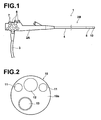
- FIG. 1 schematically illustrates an exemplary embodiment of an endoscope insertion section in which a distal optical system of the present invention is employed.
- Endoscope 1 shown in Figure 1 has a structure in which insertion section 2B to be inserted into a body cavity is attached to body 2A.
- Body 2A has cable 3 optically and electrically connected thereto, button group 6 including an air/water supply button, a suction button, a shutter button, and the like, and angle knob 7 for bending deformable section 5.
- Insertion section 2B includes flexible section 4 extending from body 2A, deformable section 5 which is bent by the operation of angle knob 7 connected to flexible section 4, and distal end section 10 provided at the tip of deformable section 5. Distal end section 10 can be directed to a desired direction in which an observation region is located by the operation of angle knob 7.
- FIG. 2 schematically illustrates an example of distal end section 10 of the endoscope.
- Figure 3 illustrates, in cross section, an example of illumination window in distal end section 10.
- distal end section 10 includes illumination lenses 11, objective lens 12, and forceps opening 13.
- Illumination lenses 11 output illumination light emitted from a light source and guided through light guide 30, constituting an illumination window.
- Objective lens 12 focuses light representing a subject image, and the focused subj ect image is formed into an endoscope image by a not shown imaging device, such as CCD.
- a treatment tool is inserted into forceps opening 13 and the treatment tool may protrude from the distal end section 10.
- distal end section 10 includes distal end member 20 formed in a substantially cylindrical shape and distal end cap 10a made of, for example, a metal member and attached to distal end member 20.
- Illumination lens 11 is accommodated in through-hole 21 formed in distal end member 20 and fixed to distal end member 20 by adhesive or caulking.
- light guide 30 which is, for example, an optical fiber bundle is fixed to the inside of through-hole 21 using a ferrule.
- Illumination lens 11 has a positive aspheric surface 11a where light enters and exit surface 11b where the light entered from positive lens surface 11a exits to the outside and substantially cylindrical side surface 11c is formed between positive surface 11a and output surface 11b.
- light guide 30 which is, for example, an optical fiber bundle is inserted in through-hole 21 and fixed therein in abutting with positive lens surface 11a or slightly separated therefrom.
- through-hole 21 is formed such that diameter ⁇ 2 of light guide accommodation section 21F for accommodating light guide 30 is not greater than diameter ⁇ 1 of cylindrical lens accommodation section 21L which is, for example, substantially corresponds to the diameter of side surface 11c . That is, an optical fiber bundle with diameter ⁇ 2 not greater than diameter ⁇ 1 of illumination lens 11 is used as light guide 30. This may realize a small diameter endoscope.
- lens accommodation section 21L is formed in a substantially cylindrical shape and side surface 11c of illumination lens 11 is also formed in a substantially cylindrical shape in Figure 3 , resulting in that a space for the optical path of light is provided in front of positive lens surface 11a.
- illumination lens 11 needs to be positioned and fixed by an adhesive or the like in through-hole 21 of distal end member 20.
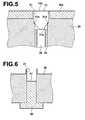
- latch piece 21a is provided, as in Figure 5 , illumination lens 11 may be inserted into through-hole 21 and fixed by an adhesive while being held by latch piece 21a.
- latch piece 21a for latching illumination lens 11 are not provided, which poses a problem that the positioning of illumination lens 11 in the depth direction of through-hole 21 is difficult. Consequently, illumination lens 11 is fixed to distal end member 20 in the manner shown in Figures 6 to 8 .
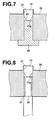
- FIGs 6 to 8 schematically illustrates an exemplary embodiment of the assembly method of an illumination optical system for an endoscope of the present invention.
- the assembly method will be described with reference to Figures 1 to 8 .
- positioning zig 40 is inserted into through-hole 21 from a first end.
- Tip surface 41 of positioning zig 40 is formed, for example, substantially flat, and the position of tip surface 41 is determined such that positive lens surface 11a of illumination lens 11 locates at a predetermined position.
- illumination lens 11 is inserted, from the side of positive lens surface 11a, into through-hole 21 from a second end. Then, positive lens surface 11a of illumination lens 11 is held by tip surface 41 of positioning zig 40. Under this state, illumination lens 11 is fixed in through-hole 21 by applying an adhesive between side surface 11c of illumination lens 11 and through-hole. After illumination lens 11 is fixed to distal end member 20, positioning zig 40 is drawn from through-hole 21.
- an optical fiber bundle that is, light guide 30, is inserted into through-hole 21 from the first end and fixed therein in abutting with positive lens surface 11a. Finally, illumination lens 11 and light guide 30 are caulked to distal end member 20.
- positive lens surface 11a may be positioned at a predetermined position of distal end member 20 without providing latch piece 21a between positive lens surface 11a and light guide 30. Consequently, there is no light blocking area between positive lens surface 11a and light guide 30, so that substantially the entirety of positive lens surface 11a may be used as the effective diameter.
- the light outputted from light guide 30 spreads according to the numerical aperture (NA) of the optical fiber bundle and reaches as far as an edge portion of positive lens surface 11a ( Figure 4 ) . Therefore, it is desirable to make even the edge portion of positive lens surface 11a function as the lens.
- the portion of the positive lens surface corresponding to the latch piece 21a is covered, possibly resulting in light amount loss of 10%.
- the light amount loss may be minimized by assembling illumination lens 11 and light guide 30 without providing a light blocking member between them.
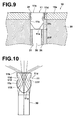
- FIGs 9 and 10 schematically illustrate an exemplary embodiment of the illumination lens for an endoscope of the present invention. Illumination lens 11 will be described with reference. to Figures 9 and 10 .
- illumination lens shown in Figures 9 and 10 components identical to those in illumination lens shown in Figures 3 and 4 are given the same reference numerals and will not be elaborated upon further here.
- the illumination lens shown in Figures 9 and 10 differs from the illumination lens shown in Figures 3 and 4 in that it has groove 11d.
- illumination lens 11 needs to be positioned in through-hole 21 of distal end member 20 and fixed by an adhesive or the like as described above.
- the amount of adhesive is excessive, some of the adhesive flows out to positive lens surface 11a from the side surface, and an outer circumferential region turns into a light blocking area.
- Groove 11d is formed in non-optical path area 11Y of illumination lens 11 where light does to path through. That is, illumination lens 11 includes optical path area 11X where the light inputted from positive lens surface 11a passes through to light exit surface 11b and non-optical path area 11Y, formed on the side of side surface 11c, where the light does not pass through. Groove 11d is formed in non-optical path area 11Y, so that the light outputted from exit surface 11b is not affected by groove 11d in any way. Optical path area 11X and non-optical path area 11Y are uniquely determined by the curvature of positive lens surface 11a, the diameter and length of illumination lens 11, and the like.
- Groove 11d is formed in a ring shape along substantially cylindrical side surface 11c and in a streamline shape toward the axis direction. Accordingly, a space is defined between illumination lens 11 and distal end member 20.
- the adhesive is filled in groove 11d, forming an adhesive layer. Note that the adhesive layer may be formed in a portion of groove 11d, and the adhesive is not necessarily filled in the entire space in groove 11d.
- groove 11d is formed in a streamline shape so that, when the adhesive is flowed from exit surface 11b toward positive lens surface 11a, the adhesive may be flowed along side surface 11c and steadily into groove 11d.
- the adhesive trap is provided on the side of through-hole 11, but it poses problems that it is difficult to form a groove on the side of through-hole 11 and the area occupied by illumination optical system in distal end section 10 is increased by a corresponding amount that the adhesive trap is formed on the outside, which is unfavorable for realizing a small diameter endoscope.
- formation of groove 11d on the side of illumination lens 11 allows ease of work and realization of a small diameter endoscope. Further, this eliminates the need for delicate application amount control of adhesive, resulting in reduced work for the manufacture and improved yield rate.
- the distal end section of the endoscope includes distal end member 20 having through-hole 21 formed therein, illumination lens 11 having positive lens surface 11a and substantially cylindrical side surface 11c, and light guide 30 fixed in through-hole 21 of distal end member 20 so as to face positive lens surface 11a of illumination lens 11.
- Through-hole 21 has substantially cylindrical lens accommodation section 21L for accommodating illumination lens 11 and light guide accommodation section 21F, in communication with lens accommodation section 21L, for accommodating light guide 30.
- Illumination lens 11 is fixed, at side surface 11c, to the inside of lens accommodation section 21L such that light outputted from light guide 30 is incident on outer circumferential region 11x of positive lens surface 11a, whereby, when illumination lens 11 is fixed to the inside of lens accommodation section 21L, a space for the optical path of light free from the blockage of distal end member 20 is provided in front of positive lens surface 11a. This allows the effective diameter of positive lens surface 11a to be extended to outer circumferential region 11x, resulting in reduced light amount loss at illumination lens 11.
- provision of groove 11d in non-optical path area 11Y of side surface 11c of illumination lens 11 for trapping an adhesive allows the adhesive to be deposited in the groove and prevented from flowing out to the side of positive lens surface 11a, so that positive lens surface 11a of illumination lens 11 is not blocked at all and the entire surface may be used as the effective diameter, whereby light amount loss at illumination lens 11 is prevented.
- side surface 11c is formed in a substantially cylindrical shape and groove 11d is formed in a ring shape along a circumference of side surface 11c, the adhesive outflow may be prevented reliably over the entire circumference of positive lens surface 11a.
- groove 11d in a streamline shape toward the axis direction causes the adhesive to flow into groove 11d easily, so that the adhesive outflow is prevented reliably over the entire circumference of positive lens surface 11a.
- illumination lens 11 has positive lens surface 11a and flat exit surface 11b, but the present invention is applicable to illumination lens 11 of any shape as long as at least either one of the surfaces is positive lens surface 11a.
- illumination lens 11 and light guide 30 are disposed directly opposite to each other, but an optical member, such as a tubular reflecting mirror, a lens, or the like, may be provided between illumination lens 11 and light guide 30, if configured such that light is incident on outer circumferential region 11x of positive lens surface 11a.
- an optical member such as a tubular reflecting mirror, a lens, or the like
- groove 11d is formed in a ring shape, for example, in Figure 9 or 10 , but the groove may be formed in a spiral shape along side surface 11c. Further, the description has been made of a case in which groove 11d has a streamline shape in cross section, but it may have a rectangular shape.
Landscapes
- Physics & Mathematics (AREA)
- General Physics & Mathematics (AREA)
- Optics & Photonics (AREA)
- Astronomy & Astrophysics (AREA)
- Endoscopes (AREA)
- Instruments For Viewing The Inside Of Hollow Bodies (AREA)
Abstract
Description
- The present invention relates to an illumination optical system for an endoscope that constitutes an illumination window, provided at the distal end of the endoscope, for emitting illumination light to a subject and an assembly method thereof.
- A wide-angle illumination optical system is used for an endoscope in order to emit illumination light having an appropriate illuminance distribution onto a subject in a body cavity. Japanese Unexamined Patent Publication Nos.
5(1993)-119272 5(1993)-157967 - Japanese Unexamined Patent Publication No.
2005-074015 - Each of such illumination lenses is attached to a distal end member of an endoscope, for example, by applying an adhesive between the illumination lens and the distal end member. Japanese Unexamined Patent Publication No.
2002-078672 - Even when such a lens as described in Patent Document 1 is used, the lens properties may not be fully utilized unless the lens is appropriately mounted in the distal end of an endoscope. That is, it is desirable that the entirety of the positive lens surface of the illumination lens is used as the effective diameter, but Patent Document 1 poses a problem that a light blocking area is formed on the positive lens surface, thereby causing light amount loss.
- When using such an illumination lens as described in Patent Document 1 or
Patent Document 2, it is conceivable that the illumination lens is fixed, at the side surface, to the distal end member using an adhesive, as described inPatent Document 4. But, it is difficult to control the amount of adhesive which poses a problem that the adhesive may sometimes flow out to the positive lens surface, thereby causing light amount loss. In particular, the illumination lens described in Patent Document 1 orPatent Document 2 is fixed to the inside of a through-hole, so that Patent Document 1 andPatent Document 2 pose a problem that the margin for trapping the adhesive as described inPatent Document 4 can not be provided at the bottom. - In view of the circumstances described above, it is an object of the present invention to provide an illumination optical system for an endoscope in which the entirety of a positive lens surface is allowed to be used as the effective diameter, and an assembly method thereof.
- An illumination optical system for an endoscope according to the present invention is an illumination optical system which includes a distal end member with a through-hole, an illumination lens, fixed to the inside of the through-hole of the distal endmember, having a positive lens surface and a side surface formed in a substantially cylindrical shape, and a light guide fixed to the inside of the through-hole of the distal end member so as to face the positive lens surface of the illumination lens, in which the through-hole has a lens accommodation section, having a substantially cylindrical shape, for accommodating the illumination lens and a light guide accommodation section, in communication with the lens accommodation section, for accommodating the light guide, and illumination lens is fixed, at the side surface, to the inside of the lens accommodation section such that light outputted from the light guide is incident on an outer circumferential region of the positive lens surface.
- An assembly method of an illumination optical system for an endoscope according to the present invention is a method for fixing an illumination lens having a positive lens surface and a side surface formed in a substantially cylindrical shape to the inside of a through-hole formed in a substantially cylindrical shape in a distal end member, the method including the steps of inserting a positioning zig into the through-hole from a first end, inserting the illumination lens, from the side of the positive lens surface, into the through-hole from a second end, and fixing the illumination lens, at the side surface, to the inside of the through-hole while holding the positive lens surface by a tip surface of the positioning zig.
- Here, the illumination lens may be any illumination lens as long as it has a positive lens surface on at least either one of the sides, but preferably, it is an illumination lens having an aspheric positive lens surface whose curvature gradually becomes smaller than the approximated curvature toward the outer circumference from the optical axis.
- The diameter of the light guide accommodation section may be not greater than the diameter of the illumination lens accommodation section.
- Further, the illumination lens may have a groove, in which an adhesive is filled, in a non-optical path area of the side surface. Here, the groove may have any shape as long as it is formed in the side surface, and it may formed, for example, in a U-shape, a rectangular shape, or a streamline shape. Further, the groove may be any groove as long as it functions as an adhesive trap in which an adhesive is filled. For example, when fixing the illumination lens to the distal end member, an adhesive may be applied to the groove before inserting the illumination lens into the through-hole, or inserting the illumination lens into the through-hole first and then injecting the adhesive to the side of the illumination lens to cause the groove to function as the adhesive trap.
- Still further, the groove may have any depth as long as it is within the non-optical path area which is uniquely determined by the curvature of the positive lens surface, the diameter and total length of the illumination lens, and the like.
- According to the illumination optical system for an endoscope of the present invention, the system includes a distal end member with a through-hole, an illumination lens, fixed to the inside of the through-hole of the distal end member, having a positive lens surface and a side surface formed in a substantially cylindrical shape, and a light guide fixed to the inside of the through-hole of the distal end member so as to face the positive lens surface of the illumination lens, in which the through-hole has a lens accommodation section, having a substantially cylindrical shape, for accommodating the illumination lens and a light guide accommodation section, in communication with the lens accommodation section, for accommodating the light guide, and illumination lens is fixed, at the side surface, to the inside of the lens accommodation section such that light outputted from the light guide is incident on an outer circumferential region of the positive lens surface. Thus, when the illumination optical system is fixed to the inside of the lens accommodation section, this may provide a space for the optical path of light free from the blockage of the distal end member in front of the positive lens surface so that the effective diameter of the positive lens surface is extended to the outer circumferential region and light amount loss at the illumination lens may be prevented.
- Further, a groove provided in a non-optical path area of the side surface of the illumination lens may trap an adhesive, so that the adhesive is prevented from flowing out to the positive lens surface side. Accordingly, the positive lens surface of the illumination lens is not blocked and the entire surface may be used as the effective diameter, whereby light amount loss at the illumination lens may be prevented.
- Where the groove is formed in a ring shape along a circumference of the side surface, an adhesive outflow may be prevented reliably over the entire circumference of the positive lens surface.
- Further, formation of the groove in a streamline shape toward the axis direction allows an adhesive to flow into the groove easily, so that an adhesive outflow is prevented reliably over the entire circumference of positive lens surface.
- According to the assembly method of an illumination optical system for an endoscope of the present invention, the method is for use in fixing an illumination lens having a positive lens surface and a side surface formed in a substantially cylindrical shape to the inside of a through-hole formed in a substantially cylindrical shape in a distal end member, and the method includes the steps of inserting a positioning zig into the through-hole from a first end, inserting the illumination lens, from the side of the positive lens surface, into the through-hole from a second end, and fixing the illumination lens, at the side surface, to the inside of the through-hole while holding the positive lens surface by a tip surface of the positioning zig. This eliminates the need for providing a latch piece for positioning the illumination lens on the side of the distal end member when assembling the illumination lens, so that the positive lens surface is not blocked by the latch piece and the entirety of the positive lens surface may be used as the effective diameter, whereby light amount loss at the illumination lens may be prevented.
- Where the diameter of the light guide accommodation section is not greater than the diameter of the lens accommodation section, a small diameter endoscope may be realized by reducing the size of the light guide.
-
-
Figure 1 schematically illustrates an exemplary embodiment of an endoscope in which an illumination optical system of the present invention is employed. -
Figure 2 schematically illustrates an example of distal end section of the endoscope shown inFigure 1 . -
Figure 3 illustrates an exemplary embodiment of the illumination optical system of the present invention in cross-section. -
Figure 4 illustrates an example of optical path of light outputted from the light guide shown inFigure 3 . -
Figure 5 illustrates an example of illumination optical system in cross section with a latch piece provided in the through-hole. -
Figure 6 schematically illustrates an assembly process of the assembling method of an illumination optical system for an endoscope of the present invention. -
Figure 7 schematically illustrates an assembly process of the assembling method of an illumination optical system for an endoscope of the present invention. -
Figure 8 schematically illustrates an assembly process of the assembling method of an illumination optical system for an endoscope of the present invention. -
Figure 9 illustrates an exemplary embodiment of an illumination lens of the present invention in cross section. -
Figure 10 illustrates an example of optical path of light outputted from the light guide shown inFigure 9 . - Hereinafter, embodiments of the present invention will be described in detail with reference to the accompanying drawings.
Figure 1 schematically illustrates an exemplary embodiment of an endoscope insertion section in which a distal optical system of the present invention is employed. Endoscope 1 shown inFigure 1 has a structure in whichinsertion section 2B to be inserted into a body cavity is attached tobody 2A.Body 2A hascable 3 optically and electrically connected thereto,button group 6 including an air/water supply button, a suction button, a shutter button, and the like, andangle knob 7 for bendingdeformable section 5.Insertion section 2B includesflexible section 4 extending frombody 2A,deformable section 5 which is bent by the operation ofangle knob 7 connected toflexible section 4, anddistal end section 10 provided at the tip ofdeformable section 5.Distal end section 10 can be directed to a desired direction in which an observation region is located by the operation ofangle knob 7. -
Figure 2 schematically illustrates an example ofdistal end section 10 of the endoscope.Figure 3 illustrates, in cross section, an example of illumination window indistal end section 10. InFigure 2 ,distal end section 10 includesillumination lenses 11,objective lens 12, and forceps opening 13.Illumination lenses 11 output illumination light emitted from a light source and guided throughlight guide 30, constituting an illumination window.Objective lens 12 focuses light representing a subject image, and the focused subj ect image is formed into an endoscope image by a not shown imaging device, such as CCD. A treatment tool is inserted into forceps opening 13 and the treatment tool may protrude from thedistal end section 10. - In
Figure 3 ,distal end section 10 includesdistal end member 20 formed in a substantially cylindrical shape anddistal end cap 10a made of, for example, a metal member and attached todistal end member 20.Illumination lens 11 is accommodated in through-hole 21 formed indistal end member 20 and fixed to distalend member 20 by adhesive or caulking. Further,light guide 30 which is, for example, an optical fiber bundle is fixed to the inside of through-hole 21 using a ferrule. -
Illumination lens 11 has a positiveaspheric surface 11a where light enters andexit surface 11b where the light entered frompositive lens surface 11a exits to the outside and substantiallycylindrical side surface 11c is formed betweenpositive surface 11a andoutput surface 11b.Positive lens surface 11a has an aspheric shape such that the curvature gradually becomes smaller than the approximated curvature along the diameter direction ofillumination lens 11 from the optical axis. More specifically,positive lens surface 11a is formed so as to satisfy h = f·θ (h = f·sinθ), where h is the incident light height, f is the focal length, and θ is the exit angle of light exiting fromexit surface 11b. This allows illumination light with an appropriate illuminance distribution to be emitted to a spherical or tubular subject.Illumination lens 11 is described in detail in Japanese Unexamined Patent Publication5 (1993) -119272 - In the mean time,
light guide 30 which is, for example, an optical fiber bundle is inserted in through-hole 21 and fixed therein in abutting withpositive lens surface 11a or slightly separated therefrom. In particular, through-hole 21 is formed such that diameter ϕ2 of lightguide accommodation section 21F for accommodatinglight guide 30 is not greater than diameter ϕ1 of cylindricallens accommodation section 21L which is, for example, substantially corresponds to the diameter ofside surface 11c . That is, an optical fiber bundle with diameter ϕ2 not greater than diameter ϕ1 ofillumination lens 11 is used aslight guide 30. This may realize a small diameter endoscope. - As shown in
Figure 4 , light outputted fromlight guide 30 is inputted topositive lens surface 11 ofillumination lens 11 and reachesexit surface 11b by refracted at different angles according to the position, then directed to a subject from theexit surface 11b. As can be seen, there is no light blocking area that blocks the light in the space from the place where the light is outputted fromlight guide 30 to the place where the light is inputted toillumination lens 11. Accordingly, substantially the entirety ofpositive lens surface 11a, including outercircumferential region 11x, can be used as the effective diameter. - That is, as shown in
Figure 5 , iflatch piece 21a is provided in through-hole 21 for holding orpositioning illumination lens 11, the light outputted fromlight guide 30 is blocked bylatch piece 21a, so that the portion ofillumination lens 11 covered bylatch piece 21a is not able to function as the lens. In contrast,lens accommodation section 21L is formed in a substantially cylindrical shape andside surface 11c ofillumination lens 11 is also formed in a substantially cylindrical shape inFigure 3 , resulting in that a space for the optical path of light is provided in front ofpositive lens surface 11a. That is, there is no light blocking member betweenillumination lens 11 andlight guide 30, so that the light outputted fromlight guide 30 is not blocked by the latch piece or the like and substantially the entirety ofpositive lens surface 11a, including outercircumferential region 11x, can be used as the effective diameter. - In the mean time,
illumination lens 11 needs to be positioned and fixed by an adhesive or the like in through-hole 21 ofdistal end member 20. Wherelatch piece 21a is provided, as inFigure 5 ,illumination lens 11 may be inserted into through-hole 21 and fixed by an adhesive while being held bylatch piece 21a. InFigure 3 , on the other hand, latchpiece 21a for latchingillumination lens 11 are not provided, which poses a problem that the positioning ofillumination lens 11 in the depth direction of through-hole 21 is difficult. Consequently,illumination lens 11 is fixed todistal end member 20 in the manner shown inFigures 6 to 8 . -
Figures 6 to 8 schematically illustrates an exemplary embodiment of the assembly method of an illumination optical system for an endoscope of the present invention. The assembly method will be described with reference toFigures 1 to 8 . As shown inFigure 6 ,positioning zig 40 is inserted into through-hole 21 from a first end.Tip surface 41 ofpositioning zig 40 is formed, for example, substantially flat, and the position oftip surface 41 is determined such thatpositive lens surface 11a ofillumination lens 11 locates at a predetermined position. - Thereafter, as shown in
Figure 7 ,illumination lens 11 is inserted, from the side ofpositive lens surface 11a, into through-hole 21 from a second end. Then,positive lens surface 11a ofillumination lens 11 is held bytip surface 41 ofpositioning zig 40. Under this state,illumination lens 11 is fixed in through-hole 21 by applying an adhesive betweenside surface 11c ofillumination lens 11 and through-hole. Afterillumination lens 11 is fixed todistal end member 20, positioningzig 40 is drawn from through-hole 21. - Then, as shown in
Figure 8 , an optical fiber bundle, that is,light guide 30, is inserted into through-hole 21 from the first end and fixed therein in abutting withpositive lens surface 11a. Finally,illumination lens 11 andlight guide 30 are caulked todistal end member 20. - As illustrated in
Figures 6 to 8 , by fixingillumination lens 11 todistal end member 20 usingpositioning zig 40,positive lens surface 11a may be positioned at a predetermined position ofdistal end member 20 without providinglatch piece 21a betweenpositive lens surface 11a andlight guide 30. Consequently, there is no light blocking area betweenpositive lens surface 11a andlight guide 30, so that substantially the entirety ofpositive lens surface 11a may be used as the effective diameter. - That is, the light outputted from light guide 30 (optical fiber bundle) spreads according to the numerical aperture (NA) of the optical fiber bundle and reaches as far as an edge portion of
positive lens surface 11a (Figure 4 ) . Therefore, it is desirable to make even the edge portion ofpositive lens surface 11a function as the lens. But, wherelatch piece 21a is formed for latchingillumination lens 11, as shown inFigure 5 , the portion of the positive lens surface corresponding to thelatch piece 21a is covered, possibly resulting in light amount loss of 10%. In contrast, as shown inFigure 3 , the light amount loss may be minimized by assemblingillumination lens 11 andlight guide 30 without providing a light blocking member between them. -
Figures 9 and 10 schematically illustrate an exemplary embodiment of the illumination lens for an endoscope of the present invention.Illumination lens 11 will be described with reference. toFigures 9 and 10 . In illumination lens shown inFigures 9 and 10 , components identical to those in illumination lens shown inFigures 3 and 4 are given the same reference numerals and will not be elaborated upon further here. The illumination lens shown inFigures 9 and 10 differs from the illumination lens shown inFigures 3 and 4 in that it hasgroove 11d. - That is,
illumination lens 11 needs to be positioned in through-hole 21 ofdistal end member 20 and fixed by an adhesive or the like as described above. Here, if the amount of adhesive is excessive, some of the adhesive flows out topositive lens surface 11a from the side surface, and an outer circumferential region turns into a light blocking area. On the other hand, there is a problem that it is difficult to control the application amount of adhesive. Consequently, as shown inFigures 9 and 10 ,groove 11d is formed inside surface 11c as adhesive trap. -
Groove 11d is formed innon-optical path area 11Y ofillumination lens 11 where light does to path through. That is,illumination lens 11 includesoptical path area 11X where the light inputted frompositive lens surface 11a passes through tolight exit surface 11b andnon-optical path area 11Y, formed on the side ofside surface 11c, where the light does not pass through.Groove 11d is formed innon-optical path area 11Y, so that the light outputted fromexit surface 11b is not affected bygroove 11d in any way.Optical path area 11X andnon-optical path area 11Y are uniquely determined by the curvature ofpositive lens surface 11a, the diameter and length ofillumination lens 11, and the like. -
Groove 11d is formed in a ring shape along substantiallycylindrical side surface 11c and in a streamline shape toward the axis direction. Accordingly, a space is defined betweenillumination lens 11 anddistal end member 20. When an adhesive is applied betweenillumination lens 11 anddistal end member 20, the adhesive is filled ingroove 11d, forming an adhesive layer. Note that the adhesive layer may be formed in a portion ofgroove 11d, and the adhesive is not necessarily filled in the entire space ingroove 11d. - When, an excessive amount of adhesive is applied to
side surface 11c, the surplus amount of adhesive is trapped ingroove 11d and prevented from flowing out to positive lens surface side. In particular,groove 11d is formed in a streamline shape so that, when the adhesive is flowed fromexit surface 11b towardpositive lens surface 11a, the adhesive may be flowed alongside surface 11c and steadily intogroove 11d. - It is also conceivable that the adhesive trap is provided on the side of through-
hole 11, but it poses problems that it is difficult to form a groove on the side of through-hole 11 and the area occupied by illumination optical system indistal end section 10 is increased by a corresponding amount that the adhesive trap is formed on the outside, which is unfavorable for realizing a small diameter endoscope. In contrast, as shown inFigures 9 and 10 , formation ofgroove 11d on the side ofillumination lens 11 allows ease of work and realization of a small diameter endoscope. Further, this eliminates the need for delicate application amount control of adhesive, resulting in reduced work for the manufacture and improved yield rate. - According to the embodiments described above, the distal end section of the endoscope includes
distal end member 20 having through-hole 21 formed therein,illumination lens 11 havingpositive lens surface 11a and substantiallycylindrical side surface 11c, andlight guide 30 fixed in through-hole 21 ofdistal end member 20 so as to facepositive lens surface 11a ofillumination lens 11. Through-hole 21 has substantially cylindricallens accommodation section 21L for accommodatingillumination lens 11 and lightguide accommodation section 21F, in communication withlens accommodation section 21L, for accommodatinglight guide 30.Illumination lens 11 is fixed, atside surface 11c, to the inside oflens accommodation section 21L such that light outputted fromlight guide 30 is incident on outercircumferential region 11x ofpositive lens surface 11a, whereby, whenillumination lens 11 is fixed to the inside oflens accommodation section 21L, a space for the optical path of light free from the blockage ofdistal end member 20 is provided in front ofpositive lens surface 11a. This allows the effective diameter ofpositive lens surface 11a to be extended to outercircumferential region 11x, resulting in reduced light amount loss atillumination lens 11. - Further, as shown in
Figures 6 to 8 , when fixing illumination lens havingpositive lens surface 11a and substantiallycylindrical side surface 11c to the inside of substantially cylindrical through-hole 21, a positioning zig is inserted into through-hole from a first end, thenillumination lens 11 is inserted, from the side ofpositive lens surface 11a, into through-hole 21 from a second end, andillumination lens 11 is fixed, atside surface 11c, to the inside of through-hole 21 while holdingpositive lens surface 11a bytip surface 41 ofpositioning zig 40. This eliminates the need for providinglatch piece 21a on the side ofdistal end member 20 forpositioning illumination lens 11 when assemblingillumination lens 11, so that light blocking areas due to latchpiece 21a may be prevented and substantially the entirety ofpositive lens surface 11a may be used as the effective diameter. That is, light amount loss atillumination lens 11 may be prevented and a bright endoscope image may be obtained. - Still further, as shown in
Figures 9 and 10 , provision ofgroove 11d innon-optical path area 11Y ofside surface 11c ofillumination lens 11 for trapping an adhesive, allows the adhesive to be deposited in the groove and prevented from flowing out to the side ofpositive lens surface 11a, so thatpositive lens surface 11a ofillumination lens 11 is not blocked at all and the entire surface may be used as the effective diameter, whereby light amount loss atillumination lens 11 is prevented. - Further, where
side surface 11c is formed in a substantially cylindrical shape andgroove 11d is formed in a ring shape along a circumference ofside surface 11c, the adhesive outflow may be prevented reliably over the entire circumference ofpositive lens surface 11a. - Still further, formation of
groove 11d in a streamline shape toward the axis direction causes the adhesive to flow intogroove 11d easily, so that the adhesive outflow is prevented reliably over the entire circumference ofpositive lens surface 11a. - It should be appreciated that the embodiments of the present invention are not limited to those described above. For example, in
Figures 6 to 8 , the description has been made of a case in which tip surface 41 ofpositioning zig 40 is formed flat, but the tip surface may have a recess having substantially the same shape as that of the positive lens surface. This ensures thatillumination lens 11 is held reliably. - Further, in
Figures 6 to 8 , the description has been made of a case in whichillumination lens 11 is inserted aftertip surface 41 ofpositioning zig 40 is positioned at a predetermined position, but the position ofillumination lens 11 may be adjusted by movingpositioning zig 40 up or down while holdingillumination lens 11. - Still further, in the embodiments, the description has been made of a case in which
illumination lens 11 haspositive lens surface 11a andflat exit surface 11b, but the present invention is applicable toillumination lens 11 of any shape as long as at least either one of the surfaces ispositive lens surface 11a. - Further, the description has been made of a case in which
illumination lens 11 andlight guide 30 are disposed directly opposite to each other, but an optical member, such as a tubular reflecting mirror, a lens, or the like, may be provided betweenillumination lens 11 andlight guide 30, if configured such that light is incident on outercircumferential region 11x ofpositive lens surface 11a. - Still further, the description has been made of a case in which
groove 11d is formed in a ring shape, for example, inFigure 9 or 10 , but the groove may be formed in a spiral shape alongside surface 11c. Further, the description has been made of a case in whichgroove 11d has a streamline shape in cross section, but it may have a rectangular shape.
Claims (7)
- An illumination optical system for an endoscope which includes a distal end member (20) with a through-hole (21), an illumination lens (11), fixed to the inside of the through-hole (21) of the distal end member (20), having a positive lens surface (11a) and a side surface (11c) formed in a substantially cylindrical shape, and a light guide (30) fixed to the inside of the through-hole (21) of the distal end member (20) so as to face the positive lens surface (1a) of the illumination lens (11), characterized in that:the through-hole (21) has a lens accommodation section (21L), having a substantially cylindrical shape, for accommodating the illumination lens (11) and a light guide accommodation section (21F), in communication with the lens accommodation section (21L), for accommodating the light guide (30); andillumination lens (11) is fixed, at the side surface (11c), to the inside of the lens accommodation section (21L) such that light outputted from the light guide (30) is incident on an outer circumferential region of the positive lens surface (11a).
- The illumination optical system for an endoscope as claimed in claim 1, characterized in that the diameter of the light guide accommodation section (21F) is not greater than the diameter of the illumination lens accommodation section (21L).
- The illumination optical system for an endoscope as claimed in claim 1 or 2, characterized in that the illumination lens (11) has a groove, in which an adhesive is filled, in a non-optical path area of the side surface (11c).
- The illumination optical system for an endoscope as claimed in claim 3, characterized in that the groove is formed in a ring shape along a circumference of the side surface (11c).
- The illumination optical system for an endoscope as claimed in claim 3 or 4, characterized in that the groove is formed in a streamline shape toward the optical axis of the illumination lens (11) .
- An assembly method of an illumination optical system for an endoscope for fixing an illumination lens (11) having a positive lens surface (11a) and a side surface (11c) formed in a substantially cylindrical shape to the inside of a through-hole (21) formed in a substantially cylindrical shape in a distal end member (20), the method comprising the steps of:inserting a positioning zig into the through-hole (21) from a first end;inserting the illumination lens (11), from the side of the positive lens surface (11a), into the through-hole (21) from a second end; andfixing the illumination lens (11), at the side surface (11c), to the inside of the through-hole (21) while holding the positive lens surface (11a) by a tip surface of the positioning zig.
- The assembly method as claimed in claim 6, characterized in that the through-hole (21) has a lens accommodation section (21L) for accommodating the illumination lens (11) and a light guide accommodation section (21F), in communication with the lens accommodation section (21L), for accommodating a light guide (30), and the diameter of the light guide accommodation section (21F) is not greater than the diameter of the illumination lens accommodation section (21L).
Applications Claiming Priority (2)
| Application Number | Priority Date | Filing Date | Title |
|---|---|---|---|
| JP2008073855A JP2009225947A (en) | 2008-03-21 | 2008-03-21 | Illumination optics for endoscope and its assembly method |
| JP2008075898A JP2009226035A (en) | 2008-03-24 | 2008-03-24 | Illumination lens for endoscope |
Publications (2)
| Publication Number | Publication Date |
|---|---|
| EP2105779A2 true EP2105779A2 (en) | 2009-09-30 |
| EP2105779A3 EP2105779A3 (en) | 2009-11-18 |
Family
ID=40941824
Family Applications (1)
| Application Number | Title | Priority Date | Filing Date |
|---|---|---|---|
| EP09004050A Withdrawn EP2105779A3 (en) | 2008-03-21 | 2009-03-20 | Illumination optical system for endoscope and assembly method thereof |
Country Status (1)
| Country | Link |
|---|---|
| EP (1) | EP2105779A3 (en) |
Citations (2)
| Publication number | Priority date | Publication date | Assignee | Title |
|---|---|---|---|---|
| JP2002078672A (en) | 2000-09-07 | 2002-03-19 | Asahi Optical Co Ltd | Endoscope lighting system |
| JP2005074015A (en) | 2003-09-01 | 2005-03-24 | Olympus Corp | Endoscope |
Family Cites Families (6)
| Publication number | Priority date | Publication date | Assignee | Title |
|---|---|---|---|---|
| JPS61249012A (en) * | 1985-04-27 | 1986-11-06 | Olympus Optical Co Ltd | Optical element having fixing groove |
| CA2075489C (en) * | 1990-01-08 | 2002-01-01 | Leroy M. Wood | Submersible lens fiberoptic assembly |
| US5485316A (en) * | 1991-10-25 | 1996-01-16 | Olympus Optical Co., Ltd. | Illumination optical system for endoscopes |
| JP2005013708A (en) * | 2003-05-30 | 2005-01-20 | Olympus Corp | Endoscope and method for assembling it |
| JP4554267B2 (en) * | 2004-04-27 | 2010-09-29 | オリンパス株式会社 | Endoscope and endoscope system |
| JP3965170B2 (en) * | 2004-07-27 | 2007-08-29 | オリンパス株式会社 | Endoscope |
-
2009
- 2009-03-20 EP EP09004050A patent/EP2105779A3/en not_active Withdrawn
Patent Citations (2)
| Publication number | Priority date | Publication date | Assignee | Title |
|---|---|---|---|---|
| JP2002078672A (en) | 2000-09-07 | 2002-03-19 | Asahi Optical Co Ltd | Endoscope lighting system |
| JP2005074015A (en) | 2003-09-01 | 2005-03-24 | Olympus Corp | Endoscope |
Also Published As
| Publication number | Publication date |
|---|---|
| EP2105779A3 (en) | 2009-11-18 |
Similar Documents
| Publication | Publication Date | Title |
|---|---|---|
| JP4843121B2 (en) | Objective optical system | |
| US5916148A (en) | Objective optical system for endoscopes | |
| US7033317B2 (en) | Disposable endoscope and method of making a disposable endoscope | |
| US4615333A (en) | Rigid endoscope of oblique window type | |
| CN109965833A (en) | For illumination for endoscope system | |
| EP0100517A2 (en) | Optical fiber sensor | |
| JP2004191866A (en) | Lighting equipment | |
| JP2004016455A (en) | Endoscope tip | |
| CN102884367B (en) | Light source device | |
| JP5345171B2 (en) | Endoscope | |
| JP2015027324A (en) | Endoscope | |
| JP6600751B2 (en) | Light guide member fixing unit, lighting device and endoscope | |
| EP2105779A2 (en) | Illumination optical system for endoscope and assembly method thereof | |
| JP2008206624A (en) | Tip part for ultrafine diameter electronic endoscope | |
| JP2000221416A (en) | Optical path conversion optical system | |
| CN110269583A (en) | Point for sighting device | |
| JP2009225947A (en) | Illumination optics for endoscope and its assembly method | |
| US20060235274A1 (en) | Rigid endoscope optics with a compound housing | |
| JP2009226035A (en) | Illumination lens for endoscope | |
| JP6865305B2 (en) | Imaging optics, endoscopes and imaging devices | |
| WO2009151158A1 (en) | Lens system | |
| JP4197786B2 (en) | Endoscope illumination optics | |
| JP4538297B2 (en) | Endoscope | |
| JP4021187B2 (en) | End of the endoscope | |
| JPS636724Y2 (en) |
Legal Events
| Date | Code | Title | Description |
|---|---|---|---|
| PUAI | Public reference made under article 153(3) epc to a published international application that has entered the european phase |
Free format text: ORIGINAL CODE: 0009012 |
|
| AK | Designated contracting states |
Kind code of ref document: A2 Designated state(s): AT BE BG CH CY CZ DE DK EE ES FI FR GB GR HR HU IE IS IT LI LT LU LV MC MK MT NL NO PL PT RO SE SI SK TR |
|
| AX | Request for extension of the european patent |
Extension state: AL BA RS |
|
| PUAL | Search report despatched |
Free format text: ORIGINAL CODE: 0009013 |
|
| AK | Designated contracting states |
Kind code of ref document: A3 Designated state(s): AT BE BG CH CY CZ DE DK EE ES FI FR GB GR HR HU IE IS IT LI LT LU LV MC MK MT NL NO PL PT RO SE SI SK TR |
|
| AX | Request for extension of the european patent |
Extension state: AL BA RS |
|
| RIC1 | Information provided on ipc code assigned before grant |
Ipc: G02B 23/24 20060101AFI20090820BHEP Ipc: G02B 3/00 20060101ALI20091012BHEP Ipc: G02B 7/02 20060101ALI20091012BHEP |
|
| 17P | Request for examination filed |
Effective date: 20100518 |
|
| AKX | Designation fees paid |
Designated state(s): DE FR GB |
|
| 17Q | First examination report despatched |
Effective date: 20120215 |
|
| STAA | Information on the status of an ep patent application or granted ep patent |
Free format text: STATUS: THE APPLICATION IS DEEMED TO BE WITHDRAWN |
|
| 18D | Application deemed to be withdrawn |
Effective date: 20161001 |