EP2105755A1 - Ladezustandsschätzverfahren für eine Fahrzeugbatterie - Google Patents
Ladezustandsschätzverfahren für eine Fahrzeugbatterie Download PDFInfo
- Publication number
- EP2105755A1 EP2105755A1 EP09003661A EP09003661A EP2105755A1 EP 2105755 A1 EP2105755 A1 EP 2105755A1 EP 09003661 A EP09003661 A EP 09003661A EP 09003661 A EP09003661 A EP 09003661A EP 2105755 A1 EP2105755 A1 EP 2105755A1
- Authority
- EP
- European Patent Office
- Prior art keywords
- battery
- state
- charge
- voltage
- adaptation
- Prior art date
- Legal status (The legal status is an assumption and is not a legal conclusion. Google has not performed a legal analysis and makes no representation as to the accuracy of the status listed.)
- Withdrawn
Links
Images
Classifications
-
- G—PHYSICS
- G01—MEASURING; TESTING
- G01R—MEASURING ELECTRIC VARIABLES; MEASURING MAGNETIC VARIABLES
- G01R31/00—Arrangements for testing electric properties; Arrangements for locating electric faults; Arrangements for electrical testing characterised by what is being tested not provided for elsewhere
- G01R31/36—Arrangements for testing, measuring or monitoring the electrical condition of accumulators or electric batteries, e.g. capacity or state of charge [SoC]
- G01R31/382—Arrangements for monitoring battery or accumulator variables, e.g. SoC
- G01R31/3828—Arrangements for monitoring battery or accumulator variables, e.g. SoC using current integration
-
- G—PHYSICS
- G01—MEASURING; TESTING
- G01R—MEASURING ELECTRIC VARIABLES; MEASURING MAGNETIC VARIABLES
- G01R31/00—Arrangements for testing electric properties; Arrangements for locating electric faults; Arrangements for electrical testing characterised by what is being tested not provided for elsewhere
- G01R31/36—Arrangements for testing, measuring or monitoring the electrical condition of accumulators or electric batteries, e.g. capacity or state of charge [SoC]
- G01R31/367—Software therefor, e.g. for battery testing using modelling or look-up tables
Definitions
- the present invention relates to a method for estimating the charge of a battery of a motor vehicle.
- the state of charge which indicates, in percentage, the charge of the battery in relation to its maximum load. This state of charge must be able to be determined regardless of the type of battery used in the motor vehicle.
- the state of health of the battery is also used, which is a function of various internal parameters of the battery such as, in particular, the internal resistance of the battery, the maximum charge capacity of this battery and the charge acceptance corresponding to the voltage at the battery. beyond which the charge of the battery is no longer effective.
- the present invention relates more particularly to the state of charge of a battery.
- This state of charge is defined according to the predefined normal conditions of use that correspond to standards that may vary from one country to another.
- the present invention therefore aims to provide a method for estimating the state of charge of a battery in a motor vehicle.
- This method will preferably be used in real time and may be implemented in a cheap on-board computer.
- Another object of the invention is that this estimate takes into account the main physical phenomena occurring within a drums. The process should be complex enough to provide a reliable, but not too complex, indication to facilitate its implementation.
- Another object of the present invention is to simulate the behavior of a battery in the short or medium term to predict the capacity of the battery to provide sufficient energy for a given task (for example cold start, stop and start of the engine also called "stop & go", ).
- the present invention proposes a method for estimating the charge of a battery of a motor vehicle in which at least one sensor provides the voltage across the battery, the current flowing in the battery and the temperature of the battery. it.
- Such a method thus makes it possible to respond to the technical problem explained above by estimating the state of charge of a battery permanently. Thanks to the adaptations made, the same method can be used on several batteries and also adapts to the aging of a battery.
- the current variation measurements are carried out at a frequency greater than 1 Hz.
- a frequency greater than 1 Hz For example, it is possible to provide measurements made every 10 ms or every 100 ms, for example.
- the different operating states of the battery considered in the method according to the invention can be chosen from the set comprising the open circuit operation, charging operation and discharge operation.
- At operating states of the battery in charge and in discharge correspond each time sub-operating states selected from the set comprising the operation saturated at 100%, the operation saturated to nearly 100 %, normal operation, operation loaded at 0% and operation loaded at 0%.
- a timer can be used when the battery operates in open circuit to measure the time elapsed since the opening. of the circuit.
- the present invention also relates to a computer program stored on an information carrier, said program comprising instructions for implementing an estimation method as described above, when this program is loaded and executed by a user. computer system.
- this invention relates to a computer system such as for example a computer to be embedded in a motor vehicle, characterized in that it comprises means adapted to implement an estimation method as described above.
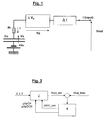
- This battery represented on the figure 1 first comprises an element at the terminals of which a voltage Ve prevails.
- the latter is generally 11.5 V.
- this element at the boundaries of which there is a constant potential difference lies on the figure 1 a capacity called Cc that allows "to store" the energy contained in the battery. When this capacity is fully charged, the voltage Vc at its terminals is about 1.3 V.
- the various elements constituting the battery have a resistor here grouped in a single resistor called Ri According to the law of Ohm, a voltage appears across the resistor when it is crossed by a current I.
- Vp bias voltage
- This voltage is positive when the battery is charging and negative when the battery is discharging.
- This bias voltage Vp results from the current flowing in the battery and the temperature at which it is located.
- This polarization comprises both a static component and a dynamic component.
- the static component of the battery is called Gp and it is assumed that this value depends on the current 1 flowing in the battery, the charge (SOC) and the temperature T of the battery, ie Gp (I, SOC, T).
- the dynamic component of the bias voltage corresponds to a first-order damping of this voltage over time.
- This damping is performed with a time constant ⁇ p.
- This time constant varies according to the state of the battery. It is thus lower during a discharge phase with respect to a charging phase.
- This time constant in open circuit, has a higher value compared to a closed circuit phase. In a manner also known, this time constant is greater in cold than in hot.
- ⁇ Vp Gp (I, SOC, T) / (1 + ⁇ p (I) .S)
- SOC state of charge of the battery
- a common way of measuring this state of charge is to fully discharge the battery until the voltage across the battery drops to measure the remaining charge Q (in Ah), then fully charge the battery and discharge it. completely again to determine the maximum load Qmax. The state of charge SOC is then the ratio between the load Q and the load Qmax measured.
- this test is long to perform, and it is also an intrusive test that changes the initial state of the battery to be measured.
- the measured Qmax value depends on the from which the battery is discharged. This is particularly apparent from the law of Peukert. Different protocols are used to achieve the discharge of the battery. This can be done for example in five hours (used especially as a standard in Japan), in twenty hours (generally used as standard in Europe) or in one hundred hours (for batteries of electric vehicles). It will be assumed for example that the maximum load Qmax used here subsequently corresponds to the maximum load measured when the battery is discharged in twenty hours. Of course, this definition of Qmax does not affect the present invention.
- sensors measure at the battery, the current, the voltage and the temperature.
- measurements are made and from these measurements are calculated changes in current and voltage variations. These measurements are, for example, performed every 10ms or 100ms.
- the parameters (current, voltage, temperature) of the battery are observed and we see how it reacts.
- a model estimates, depending on the parameters and their variations, how the battery should react. This model is adapted automatically according to the reactions of the battery which are measured.
- the model used for the battery is described above. Thereafter, are detailed calculations for estimating the voltage across the battery to determine the state of charge thereof.
- This current corresponds to the total current to which the current loss ⁇ I is withdrawn.
- This loss of current is calculated from the temperature and the voltage.
- the loss of current can be calculated by a formula or be determined by consulting a table. This loss of current is increasing with temperature and is also increasing with voltage.
- Vc n Vc n-1 - ⁇ A.h / Qmax [Ah] * Vcmax
- Vc n is the new value of the voltage Vc to be determined while Vc n-1 is the old determined value of Vc.
- ⁇ A.h corresponds to a load variation and is calculated by multiplying the value of the current (corrected) by the duration of the sampling interval. We then have: SOC + Vc / Vcmax [%]
- the voltage Vc is then determined from the state of charge SOC.
- the bias voltage has a static component and a dynamic component.
- This dynamic component being different in charge or discharge of the battery, it is proposed to cut the voltage signal Vp into two separate signals, a positive signal integrating the effects due to the load and a negative signal reflecting the effects due at the dump.
- Vp (CH) corresponds to the bias voltage under load
- Vp (DCH) corresponds to the bias voltage during a discharge.
- Vout Ve + Vc + Ri * i + Vp
- This voltage corresponds to the modeled voltage representing the response of the battery to a given current. Like any modeling, this one presents errors which it is necessary to correct. It is proposed here to make an adaptation of the model.
- the adaptation is made according to the phase in which the battery is located. It is thus possible to provide an adaptation when the battery is in open circuit, an adaptation acting on the polarization model of the battery and adaptations when the state of charge of the battery is close to 0% or 100%.
- the estimate made of the state of charge SOC can then be corrected to become equal to the corresponding value of the open circuit voltage OCV by a closed-loop integration operation of the error between the current value of the state. charge and the value of the state of charge equivalent to the open circuit voltage OCV.
- both values must be equal (and depend on the temperature).
- the gains of this operation depend on the damping of the polarization voltage and the temperature: the more the polarization is damped, the better the gains and the lower the temperature, the lower the gains.
- a timer is for example used as soon as a phase of charging or discharging the battery is completed. It can be provided that this timer is triggered when the value of the current passes below a predetermined threshold, this threshold being of course relatively low. Correction of the state of charge is then performed when the timer is engaged for a relatively long time, for example several hours. The estimation of the state of charge SOC is then converged towards the value SOC_OCV which is the state of charge corresponding to the open circuit voltage of the battery.
- a polarization adaptation can be made both during a charging phase, during a discharge phase or in open circuit.
- the polarization model is representative of the nonlinear impedances of the circuit as described above.
- the behavior of this polarization can vary widely from one battery to another and self-adaptation is therefore necessary here.
- the measured output voltage is continuously compared to the calculated output voltage.
- a correction is permanently made as a function of the difference between the measured voltage and the calculated voltage in order to compensate for the error on the bias voltage and / or the charging voltage (at the capacitance terminals) or the internal circuit voltage. open.
- a correction factor ⁇ vp is used after a charge of the battery while a factor ⁇ VpDCH is applied after a discharge phase.
- the figure 2 illustrates the estimation method according to the invention implementing adaptations both on the state of charge and on the bias voltage.
- reference 2 represents the modeling of the battery while reference 4 represents the means of self-adaptation.
- sensors measure the voltage V, the current I and the temperature T of the battery. These data are injected into the modeling of the battery 2 to provide an estimated voltage Vout_est. Moreover, this voltage Vout is measured and has the value Vout_mes. The two values are compared and the result of this comparison is introduced in the self-adaptation means 4. These then provide corrective terms ⁇ SOC_corr and ⁇ VpCH and ⁇ VpDCH.
- the strategy of combining the state of charge correction and the bias voltage is managed according to a principle diagram taking into account the current, the voltage and the temperature as well as the history of the corrections made.
- a confidence indicator regarding the bias voltage can be used. This indicator will be high after a long open circuit phase or after a long phase during which the current is substantially constant. On the other hand, the confidence in the polarization voltage will be low during transition phases or after a significant variation of the current.
- Adjustments on the value of the state of charge will therefore be performed when the confidence indicator on the polarization value is high.
- the system can automatically detect some typical situations, especially when the state of charge is close to 0% or close to 100%. During a discharge phase, when the state of charge reaches the limit of 0%, the output voltage decreases suddenly and very rapidly. This situation can be easily detected by measuring the voltage gradient.
- Vout decreases to a value of less than 10.5 V with a significant negative gradient, or if a load current reaches a very large value with however a relatively low value Vout, for example less than 13, 5 V, then, the estimation of the state of charge SOC of the battery is corrected for converge to the lower limit of 0% corresponding to the measured temperature. If the state of charge is still positive, then the estimated state of charge is reduced to 0%. On the other hand, if the estimated state of charge has already reached 0% and tends to be negative, then the state of charge is maintained at 0%.
- Vout increases and exceeds 16.5 V, with a large voltage gradient or if the charging current reaches 0A with a substantially stabilized voltage at a relatively high value, for example greater than 14 V
- the estimate the state of charge SOC is corrected to converge to the value of 100%. If the estimated state of charge is still less than 100%, then this state of charge is increased to reach the value of 100%. On the other hand, if the estimated state of charge has already reached 100% and tends to become greater than 100%, then the estimated state of charge is maintained at 100%.
- the method described above thus makes it possible to obtain a good estimate of the state of charge of a battery.
- a period of adaptation is most often necessary.
- the process described above thanks in particular to the adaptation of the polarization voltage, makes it possible to obtain a good estimate of the state of charge fairly quickly.
- the method according to the invention allows an estimation of the charge of the battery during all phases of use thereof.
- the estimated value is readjusted permanently by comparison between a modeled voltage and a measured voltage. This provides a reliable estimate of the state of charge of the battery throughout the life of the battery, even when the battery is aging.
- the present invention is an application of several methods of self-adaptation, by prediction or extrapolation, using a real-time closed-loop correction adapted for the operating phases.
Applications Claiming Priority (1)
| Application Number | Priority Date | Filing Date | Title |
|---|---|---|---|
| FR0801664A FR2929409B1 (fr) | 2008-03-27 | 2008-03-27 | Procede d'estimation de la charge d'une batterie d'un vehicule automobile |
Publications (1)
| Publication Number | Publication Date |
|---|---|
| EP2105755A1 true EP2105755A1 (de) | 2009-09-30 |
Family
ID=39929886
Family Applications (1)
| Application Number | Title | Priority Date | Filing Date |
|---|---|---|---|
| EP09003661A Withdrawn EP2105755A1 (de) | 2008-03-27 | 2009-03-13 | Ladezustandsschätzverfahren für eine Fahrzeugbatterie |
Country Status (4)
| Country | Link |
|---|---|
| US (1) | US20090248334A1 (de) |
| EP (1) | EP2105755A1 (de) |
| JP (1) | JP2009236919A (de) |
| FR (1) | FR2929409B1 (de) |
Cited By (3)
| Publication number | Priority date | Publication date | Assignee | Title |
|---|---|---|---|---|
| FR2941053A1 (fr) * | 2009-01-15 | 2010-07-16 | Peugeot Citroen Automobiles Sa | Dispositif et procede d'estimation rapide de l'etat de charge d'une batterie d'un engin a moteur, a partir d'equations non lineaires |
| FR2969304A1 (fr) * | 2010-12-17 | 2012-06-22 | Continental Automotive France | Procede de determination de l'etat de charge d'une batterie |
| CN103675686A (zh) * | 2012-09-21 | 2014-03-26 | 华北电力大学 | 电动车辆动力电池充放电工况模拟系统和方法 |
Families Citing this family (11)
| Publication number | Priority date | Publication date | Assignee | Title |
|---|---|---|---|---|
| JP4772137B2 (ja) * | 2009-06-02 | 2011-09-14 | トヨタ自動車株式会社 | バッテリ使用機器の制御装置 |
| US9201121B2 (en) * | 2010-12-06 | 2015-12-01 | Texas Instruments Incorporated | System and method for sensing battery capacity |
| US8645088B2 (en) * | 2011-05-13 | 2014-02-04 | GM Global Technology Operations LLC | Systems and methods for determining the state of charge of a battery utilizing confidence values |
| JP2013126258A (ja) * | 2011-12-13 | 2013-06-24 | Denso Corp | 2次電池の充電率相当量算出装置 |
| US9086462B2 (en) * | 2012-08-15 | 2015-07-21 | GM Global Technology Operations LLC | Systems and methods for battery parameter estimation |
| JP2015155859A (ja) * | 2014-02-21 | 2015-08-27 | ソニー株式会社 | 電池残量推定装置、電池パック、蓄電装置、電動車両および電池残量推定方法 |
| DE112016000834T5 (de) * | 2015-02-19 | 2017-11-30 | Mitsubishi Electric Corporation | Vorrichtung zum einschätzen eines batteriestatus |
| WO2017221469A1 (ja) * | 2016-06-24 | 2017-12-28 | アルプス電気株式会社 | センサモジュールおよびその電池残量監視方法 |
| US11614490B2 (en) | 2016-12-06 | 2023-03-28 | Volvo Truck Corporation | Method of estimating a charge state for a battery cell |
| KR20180084358A (ko) | 2017-01-17 | 2018-07-25 | 삼성전자주식회사 | 배터리 상태 추정 방법 및 장치 |
| CN113517736B (zh) * | 2021-05-31 | 2023-04-07 | 上海航天电源技术有限责任公司 | 一种电池组维护方法 |
Citations (5)
| Publication number | Priority date | Publication date | Assignee | Title |
|---|---|---|---|---|
| EP1231476A2 (de) * | 2001-02-13 | 2002-08-14 | Robert Bosch Gmbh | Verfahren und Anordnung zur Bestimmung der Leistungsfähigkeit einer Batterie |
| EP1505402A1 (de) * | 2003-08-06 | 2005-02-09 | VB Autobatterie GmbH | Verfahren zur Vorhersage von elektrischen Eigenschaften einer elektrochemischen Speicherbatterie |
| DE102004035858A1 (de) * | 2004-07-23 | 2006-02-16 | Robert Bosch Gmbh | Zustands- und Parameterschätzer mit Integral- und Differentialanteil für elektrische Energiespeicher |
| US20070035307A1 (en) * | 2003-01-25 | 2007-02-15 | Eberhard Schoch | State variable and parameter estimator comprising several partial models for an electrical energy storage device |
| US20080054850A1 (en) * | 2006-09-05 | 2008-03-06 | Samsung Sdi Co., Ltd. | Battery management system and driving method thereof |
Family Cites Families (3)
| Publication number | Priority date | Publication date | Assignee | Title |
|---|---|---|---|---|
| JPH11346444A (ja) * | 1998-06-02 | 1999-12-14 | Toyota Motor Corp | 電池充電状態の推定方法 |
| JP2001272444A (ja) * | 2000-03-27 | 2001-10-05 | Hitachi Maxell Ltd | 二次電池の残存容量推定装置 |
| JP2006025538A (ja) * | 2004-07-08 | 2006-01-26 | Toyota Motor Corp | 二次電池の残存容量推定方法、その残存容量推定方法をコンピュータに実行させるプログラムを記録した記録媒体および電池制御システム |
-
2008
- 2008-03-27 FR FR0801664A patent/FR2929409B1/fr not_active Expired - Fee Related
-
2009
- 2009-03-13 EP EP09003661A patent/EP2105755A1/de not_active Withdrawn
- 2009-03-26 US US12/411,819 patent/US20090248334A1/en not_active Abandoned
- 2009-03-27 JP JP2009078249A patent/JP2009236919A/ja active Pending
Patent Citations (5)
| Publication number | Priority date | Publication date | Assignee | Title |
|---|---|---|---|---|
| EP1231476A2 (de) * | 2001-02-13 | 2002-08-14 | Robert Bosch Gmbh | Verfahren und Anordnung zur Bestimmung der Leistungsfähigkeit einer Batterie |
| US20070035307A1 (en) * | 2003-01-25 | 2007-02-15 | Eberhard Schoch | State variable and parameter estimator comprising several partial models for an electrical energy storage device |
| EP1505402A1 (de) * | 2003-08-06 | 2005-02-09 | VB Autobatterie GmbH | Verfahren zur Vorhersage von elektrischen Eigenschaften einer elektrochemischen Speicherbatterie |
| DE102004035858A1 (de) * | 2004-07-23 | 2006-02-16 | Robert Bosch Gmbh | Zustands- und Parameterschätzer mit Integral- und Differentialanteil für elektrische Energiespeicher |
| US20080054850A1 (en) * | 2006-09-05 | 2008-03-06 | Samsung Sdi Co., Ltd. | Battery management system and driving method thereof |
Cited By (4)
| Publication number | Priority date | Publication date | Assignee | Title |
|---|---|---|---|---|
| FR2941053A1 (fr) * | 2009-01-15 | 2010-07-16 | Peugeot Citroen Automobiles Sa | Dispositif et procede d'estimation rapide de l'etat de charge d'une batterie d'un engin a moteur, a partir d'equations non lineaires |
| FR2969304A1 (fr) * | 2010-12-17 | 2012-06-22 | Continental Automotive France | Procede de determination de l'etat de charge d'une batterie |
| CN103675686A (zh) * | 2012-09-21 | 2014-03-26 | 华北电力大学 | 电动车辆动力电池充放电工况模拟系统和方法 |
| CN103675686B (zh) * | 2012-09-21 | 2017-01-18 | 华北电力大学 | 电动车辆动力电池充放电工况模拟系统和方法 |
Also Published As
| Publication number | Publication date |
|---|---|
| FR2929409B1 (fr) | 2010-04-02 |
| JP2009236919A (ja) | 2009-10-15 |
| FR2929409A1 (fr) | 2009-10-02 |
| US20090248334A1 (en) | 2009-10-01 |
Similar Documents
| Publication | Publication Date | Title |
|---|---|---|
| EP2105755A1 (de) | Ladezustandsschätzverfahren für eine Fahrzeugbatterie | |
| EP3028054B1 (de) | Einschätzung des zersetzungszustands einer strombatterie | |
| EP2529242B1 (de) | Verfahren zur diagnostizierung des gesundheitszustands einer batterie | |
| EP2087574B1 (de) | Verfahren zur ladungsverwaltung einer wiederaufladbaren batterie | |
| EP2233937B1 (de) | Verfahren zur Bestimmung des Gesundheitszustands einer Batterie | |
| FR2897945A1 (fr) | Dispositif destine a calculer une quantite indiquant l'etat charge d'une batterie installee sur un vehicule | |
| FR2963109A1 (fr) | Procede de determination d'un parametre d'au moins un accumulateur d'une batterie | |
| EP2850445B1 (de) | System und entsprechendes verfahren zur bestimmung des ladezustandes einer batterie | |
| WO2014206989A1 (fr) | Procede d'evaluation de l'etat de charge d'une batterie | |
| WO2017207891A1 (fr) | Procede d'estimation de l'etat de sante d'une batterie | |
| FR2977678A1 (fr) | Procede de diagnostic d'une batterie | |
| EP3667345B1 (de) | Verfahren zur bestimmung des gesundheitszustands der zellen einer batterie | |
| EP4111219A1 (de) | Verfahren zur schätzung des intaktheitsstatus einer batterie | |
| EP1187297A1 (de) | Batterieladeverfahren | |
| FR2920884A1 (fr) | Procede d'estimation de l'etat de sante d'une batterie embarquee dans un vehicule automobile. | |
| EP3948316B1 (de) | Verfahren zur initialisierung des ladezustandes einer batterie | |
| WO2023111409A1 (fr) | Procede de recalage de l'etat de charge d'un systeme de batterie | |
| EP1336857B1 (de) | Anordnung zur Bestimmung des Ladezustands einer Batterie, insbesondere zur Verwendung in einem Kraftfahrzeug | |
| WO2015097356A1 (fr) | Procédé et système de gestion de batterie pour véhicule automobile | |
| FR2942882A1 (fr) | Procede pour determiner l'etat de charge d'une source electrochimique pour la traction electrique de vehicules | |
| WO1981002066A1 (fr) | Procede de mesure de l'etat de charge d'un accumulateur et dispositif pour la mise en oeuvre de ce procede | |
| FR2965361A1 (fr) | Procede d'estimation de l'etat de sante d'une batterie d'un vehicule et vehicule mettant en oeuvre un tel procede | |
| FR2934374A1 (fr) | Procede de determination de la capacite maximale d'une batterie d'un vehicule automobile | |
| WO2013060688A1 (fr) | Procede et systeme de determination d'etat de charge d'une cellule elementaire et d'une batterie | |
| FR3046249A1 (fr) | Procede d'evaluation de l'etat de charge d'une batterie |
Legal Events
| Date | Code | Title | Description |
|---|---|---|---|
| PUAI | Public reference made under article 153(3) epc to a published international application that has entered the european phase |
Free format text: ORIGINAL CODE: 0009012 |
|
| 17P | Request for examination filed |
Effective date: 20090811 |
|
| AK | Designated contracting states |
Kind code of ref document: A1 Designated state(s): AT BE BG CH CY CZ DE DK EE ES FI FR GB GR HR HU IE IS IT LI LT LU LV MC MK MT NL NO PL PT RO SE SI SK TR |
|
| AX | Request for extension of the european patent |
Extension state: AL BA RS |
|
| 17Q | First examination report despatched |
Effective date: 20090918 |
|
| AKX | Designation fees paid |
Designated state(s): DE |
|
| STAA | Information on the status of an ep patent application or granted ep patent |
Free format text: STATUS: THE APPLICATION IS DEEMED TO BE WITHDRAWN |
|
| 18D | Application deemed to be withdrawn |
Effective date: 20161209 |