EP2105584A2 - Werkzeug zum Aufbau und Abbau einer Einlassstufe eines Verdichters einer Gasturbineneinheit, Abbauverfahren und Verfahren zum Aufbau der Stufe - Google Patents
Werkzeug zum Aufbau und Abbau einer Einlassstufe eines Verdichters einer Gasturbineneinheit, Abbauverfahren und Verfahren zum Aufbau der Stufe Download PDFInfo
- Publication number
- EP2105584A2 EP2105584A2 EP20090156080 EP09156080A EP2105584A2 EP 2105584 A2 EP2105584 A2 EP 2105584A2 EP 20090156080 EP20090156080 EP 20090156080 EP 09156080 A EP09156080 A EP 09156080A EP 2105584 A2 EP2105584 A2 EP 2105584A2
- Authority
- EP
- European Patent Office
- Prior art keywords
- inlet stage
- ring
- reinforcement element
- stage
- inlet
- Prior art date
- Legal status (The legal status is an assumption and is not a legal conclusion. Google has not performed a legal analysis and makes no representation as to the accuracy of the status listed.)
- Withdrawn
Links
- 238000000034 method Methods 0.000 title claims description 31
- 230000002787 reinforcement Effects 0.000 claims abstract description 41
- 230000008878 coupling Effects 0.000 claims description 19
- 238000010168 coupling process Methods 0.000 claims description 19
- 238000005859 coupling reaction Methods 0.000 claims description 19
- 238000012423 maintenance Methods 0.000 description 8
- 238000006073 displacement reaction Methods 0.000 description 1
- 238000007689 inspection Methods 0.000 description 1
- 239000000463 material Substances 0.000 description 1
- 230000007246 mechanism Effects 0.000 description 1
- 238000012986 modification Methods 0.000 description 1
- 230000004048 modification Effects 0.000 description 1
- 230000002093 peripheral effect Effects 0.000 description 1
- 239000002699 waste material Substances 0.000 description 1
Images


Classifications
-
- F—MECHANICAL ENGINEERING; LIGHTING; HEATING; WEAPONS; BLASTING
- F01—MACHINES OR ENGINES IN GENERAL; ENGINE PLANTS IN GENERAL; STEAM ENGINES
- F01D—NON-POSITIVE DISPLACEMENT MACHINES OR ENGINES, e.g. STEAM TURBINES
- F01D25/00—Component parts, details, or accessories, not provided for in, or of interest apart from, other groups
- F01D25/28—Supporting or mounting arrangements, e.g. for turbine casing
- F01D25/285—Temporary support structures, e.g. for testing, assembling, installing, repairing; Assembly methods using such structures
Definitions
- the present invention relates to a tool for assembling and disassembling an inlet stage of a compressor of a gas turbine unit, to a method for disassembling and to a method for assembling said stage.
- the electric power plants comprising gas turbine units are generally subjected to service and maintenance operations.
- the compressor must often be disassembled in order to carry out an inspection of the state of the parts of the compressor and, if necessary, perform maintenance or reconditioning operations of some parts of the compressor.
- the disassembly of the compressor and the subsequent assembly upon completion of the maintenance operations are particularly complex manoeuvres, during which there is a very high risk of damaging parts of the compressor.
- the compressor inlet stage comprises an inner ring, an outer ring and an array of orientable vanes, more commonly designated as IGVs (Inlet Guide Vanes), which are arranged radially between the inner ring and the outer ring.
- IGVs Inlet Guide Vanes
- the presence of orientable vanes considerably reduces the structural stiffness of the inlet stage with respect to the remaining stages of the compressor in which the vanes are fixed. Therefore, the handling of the compressor inlet stage is very difficult as the poor stiffness of the inlet stage increases the risk of compromising the structural integrity of the inlet stage itself.
- the inlet stage of the compressor comprises fine handling mechanisms for the orientable vanes, which easily suffer damages during the assembly and disassembly manoeuvres.
- the present invention relates to a tool for assembling and disassembling an inlet stage of a compressor of a gas turbine unit; the inlet stage comprising an inner ring, defined by two coupled inner half-rings, an outer ring, defined by two coupled outer half rings, and an array of orientable vanes arranged radially between the inner ring and the outer ring; the tool being characterised by comprising a reinforcement element adapted to be coupled to the inlet stage in order to increase the stiffness of the inlet stage, and a holding element rigidly connected to the reinforcement element.
- the present invention relates to a method for disassembling an inlet stage of a compressor of a gas turbine unit characterised by comprising the steps of:
- the present invention relates to a method for assembling an inlet stage of a compressor of a gas turbine unit; the inlet stage comprising an inner ring, an outer ring and an array of orientable vanes arranged radially between the inner ring and the outer ring; the method being characterized in that it comprises the steps of:
- Figure 1 shows a compressor 1 of the multistage axial type of a gas turbine unit (not shown in the accompanying figures) which comprises a shaft 2, extending along a longitudinal axis A, an inner cylindrical casing 3, which extends about a portion of shaft 2, and an outer cylindrical casing 4, which extends about shaft 2 and is defined by two half shells 5a, 5b which may be coupled to one another.
- a gas turbine unit not shown in the accompanying figures
- Compressor 1 comprises a plurality of stages (not shown in the accompanying figures) and an inlet stage 6, which comprises an inner ring 7, an outer ring 8 and an array of orientable vanes 9, which are commonly designated as IGVs (Inlet Guide Vanes).
- IGVs Inlet Guide Vanes
- Inner ring 7 is defined by two inner half rings 11a, 11b coupled to one another
- outer ring 8 is defined by two outer half rings 12a, 12b coupled to one another and adapted to be housed in an annular guide 13 of outer cylindrical casing 4.
- outer half rings 12a, 12b are adapted to be housed respectively in a first portion 13a of annular guide 13 defined in half shell 5a and in a second portion 13b of annular guide 13 defined in half shell 5b.
- Inlet stage 6 may therefore be separated into a first half 14 and a second half 15.
- First half 14 comprises an inner half ring 11a, an outer half ring 12a and orientable vanes 9 comprised between inner half ring 11a and outer half ring 12a.
- Second half 15 comprises an inner half ring 11b, an outer half ring 12b and orientable vanes 9 comprised between inner half ring 11b and outer half ring 12b.
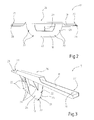
- Figure 2 shows a tool 17 for disassembling and assembling an inlet stage 6.
- Tool 17 comprises a reinforcement element 18, in particular a plate adapted to be coupled to inlet stage 6 to increase the stiffness of inlet stage 6, and a holding element 19, in particular a crossbar rigidly connected to plate 18.
- plate 18 has a substantially semicircular shape and is adapted to be coupled to one of inner half rings 11a, 11b of inlet stage 6.
- Plate 18 has a peripheral edge 21 provided with four holes 22 for the housing of screws (not shown) for the attachment of one of inner half rings 11a, 11b of inlet stage 6 and has a front face 23 and a back face 24.
- Crossbar 19 is adapted to be arranged in abutment against the ends of one of inner half rings 11a, 11b and of one of outer half rings 12a, 12b.
- Crossbar 19 has a central portion 26 which is rigidly connected to plate 18 and two end portions 27, each of which is provided with a hole 28 for housing a screw and a bolt provided with an eyelet coupled to a ring (not shown in the accompanying figures).
- Plate 18 is arranged substantially orthogonal with respect to cross bar 19.
- tool 17 comprises three support elements 29, in particular three support wings of support plate 18, which are connected to back face 24 of plate 18 and to crossbar 19 and are adapted to give greater structural stiffness to plate 18.
- Tool 17 is mainly used during the maintenance operations of a compressor 1 of a gas turbine unit.
- the maintenance method of compressor 1 substantially comprises disassembling inlet stage 6, performing the required maintenance and renewal operations of inlet stage 6 and reassembling inlet stage 6.
- the step of disassembling inlet stage 6 substantially comprises separating half shells 5a, 5b defining outer cylindrical casing 4, separating inner half rings 11a, 11b and separating outer half rings 12a, 12b, so that first half 14 of inlet stage 6 is housed in half shell 5a.
- the step of disassembling inlet stage 6 comprises removing half shell 5a of outer cylindrical casing 4, comprising first half 14 of inlet stage 6, and positioning it somewhere dedicated in a substantially vertical position.
- the step of disassembling inlet stage 6 comprises disassembling first half 14 of inlet stage 6 coupled to half shell 5a and subsequently disassembling second half 15 of inlet stage 6 coupled to half shell 5b.
- step of disassembling first half 14 of inlet stage 6 comprises:
- the step of disassembling second half 15 of inlet stage 6 comprises:
- the torque is applied by exerting a tractive force to an end portion 27 of crossbar 19, for instance by means of at least one tie-rod fixed to the ring of the nut connected to end portion 27, and pushing end portion 27 opposite to crossbar 19, for instance manually.
- first and second halves 14, 15 of inlet stage 6 are displaced in respective positions in which the maintenance and reconditioning operations are performed.
- the displacement of first and second halves 14, 15 of inlet stage 6 is performed by using tie-rods, connected to end portions 27 of crossbar 19 and to outer half ring 12a, 12b, and displaced by appropriate machines for lifting and displacing materials (for instance a bridge-crane).
- inlet stage 6 is reassembled.
- the method for assembling the inlet stage substantially comprises coupling inlet stage 6 to plate 18; and housing outer ring 8 of inlet stage 6 of compressor 1 in annular guide 13 of outer cylindrical casing 4.
- the method for assembling comprises:
- the torque is applied by exerting a tractive force to an end portion 27 of crossbar 19, for instance by means of at least one tie-rod fixed to the ring of the nut connected to end portion 27, and pushing end portion 27 opposite to crossbar 19, for instance manually.
Landscapes
- Engineering & Computer Science (AREA)
- Mechanical Engineering (AREA)
- General Engineering & Computer Science (AREA)
- Structures Of Non-Positive Displacement Pumps (AREA)
Applications Claiming Priority (1)
| Application Number | Priority Date | Filing Date | Title |
|---|---|---|---|
| ITMI20080540 ITMI20080540A1 (it) | 2008-03-28 | 2008-03-28 | Attrezzo per il montaggio e lo smontaggio di uno stadio di ingresso di un compressore di una unita' di turbina a gas, metodo di smontaggio e metodo di montaggio di tale stadio |
Publications (1)
| Publication Number | Publication Date |
|---|---|
| EP2105584A2 true EP2105584A2 (de) | 2009-09-30 |
Family
ID=40292995
Family Applications (1)
| Application Number | Title | Priority Date | Filing Date |
|---|---|---|---|
| EP20090156080 Withdrawn EP2105584A2 (de) | 2008-03-28 | 2009-03-24 | Werkzeug zum Aufbau und Abbau einer Einlassstufe eines Verdichters einer Gasturbineneinheit, Abbauverfahren und Verfahren zum Aufbau der Stufe |
Country Status (2)
| Country | Link |
|---|---|
| EP (1) | EP2105584A2 (de) |
| IT (1) | ITMI20080540A1 (de) |
-
2008
- 2008-03-28 IT ITMI20080540 patent/ITMI20080540A1/it unknown
-
2009
- 2009-03-24 EP EP20090156080 patent/EP2105584A2/de not_active Withdrawn
Also Published As
| Publication number | Publication date |
|---|---|
| ITMI20080540A1 (it) | 2009-09-29 |
Similar Documents
| Publication | Publication Date | Title |
|---|---|---|
| EP1614856B1 (de) | Vorrichtung zum Ausbauen von Schaufeln einer Turbine oder eines Verdichters | |
| CN102232146B (zh) | 风力涡轮发电机及其维护方法 | |
| US8056227B2 (en) | Turbine blade having material block and related method | |
| US6450763B1 (en) | Replaceable variable stator vane for gas turbines | |
| EP3023580A1 (de) | Gasturbine mit mehreren zugstangen und verfahren zur montage davon | |
| KR101499406B1 (ko) | 링크 기구 및 이를 구비한 가변 정익 구동 장치 | |
| CN104619954B (zh) | 用于组装或拆卸可轴向穿流的涡轮机的包括一定数量的转子构件的转子的方法和这种转子 | |
| JP4315912B2 (ja) | 機械のステータ並びに組立及び分解方法 | |
| US20190275575A1 (en) | Hydraulic extrusion tool with integrated induction device | |
| CN104246144B (zh) | 用于拆卸涡轮风扇引擎的方法和加热装置 | |
| US20150010395A1 (en) | Stator Blade Sector for an Axial Turbomachine with a Dual Means of Fixing | |
| US11215079B2 (en) | Turbomachine and method for disassembling such a turbomachine | |
| US9885386B2 (en) | Bearing assembly | |
| EP2105584A2 (de) | Werkzeug zum Aufbau und Abbau einer Einlassstufe eines Verdichters einer Gasturbineneinheit, Abbauverfahren und Verfahren zum Aufbau der Stufe | |
| EP2033741A2 (de) | Entfernungs- und Montagewerkzeug | |
| CN111511505B (zh) | 用于移除涡轮发动机的环形部件的工具 | |
| JP6678188B2 (ja) | フランジ付き機械デバイスのための組み立て/分解装置およびフランジ付き機械デバイスのための組み立て/分解方法 | |
| JP2014037827A (ja) | バランスウェイト設置システム及び関連する方法 | |
| RU71767U1 (ru) | Ключ для сборки и разборки гидравлических забойных двигателей | |
| US10471553B2 (en) | Tool for extracting a metal piece | |
| CN222874486U (zh) | 液压插装阀拆卸工具 | |
| JP5529059B2 (ja) | タービン翼連結ピン押抜き装置及びタービン翼連結ピンの押抜き方法 | |
| CN113374711B (zh) | 一种轴流风机 | |
| EP3620258B1 (de) | Verfahren zur reparatur eines rotors eines mehrstufigen axialverdichters einer gasturbine | |
| WO2025239221A1 (ja) | 回転機械の分解組立方法、及び位置決めピンの挿抜治具 |
Legal Events
| Date | Code | Title | Description |
|---|---|---|---|
| PUAI | Public reference made under article 153(3) epc to a published international application that has entered the european phase |
Free format text: ORIGINAL CODE: 0009012 |
|
| AK | Designated contracting states |
Kind code of ref document: A2 Designated state(s): AT BE BG CH CY CZ DE DK EE ES FI FR GB GR HR HU IE IS IT LI LT LU LV MC MK MT NL NO PL PT RO SE SI SK TR |
|
| AX | Request for extension of the european patent |
Extension state: AL BA RS |
|
| STAA | Information on the status of an ep patent application or granted ep patent |
Free format text: STATUS: THE APPLICATION IS DEEMED TO BE WITHDRAWN |
|
| 18D | Application deemed to be withdrawn |
Effective date: 20121002 |