EP2105550A1 - A tool for cleaning at least part of a roof - Google Patents
A tool for cleaning at least part of a roof Download PDFInfo
- Publication number
- EP2105550A1 EP2105550A1 EP08153315A EP08153315A EP2105550A1 EP 2105550 A1 EP2105550 A1 EP 2105550A1 EP 08153315 A EP08153315 A EP 08153315A EP 08153315 A EP08153315 A EP 08153315A EP 2105550 A1 EP2105550 A1 EP 2105550A1
- Authority
- EP
- European Patent Office
- Prior art keywords
- tool
- roof
- cleaning
- tool head
- state
- Prior art date
- Legal status (The legal status is an assumption and is not a legal conclusion. Google has not performed a legal analysis and makes no representation as to the accuracy of the status listed.)
- Withdrawn
Links
- 238000004140 cleaning Methods 0.000 title claims abstract description 86
- 239000007788 liquid Substances 0.000 claims description 11
- 244000007853 Sarothamnus scoparius Species 0.000 claims description 8
- 239000000463 material Substances 0.000 description 13
- 238000007790 scraping Methods 0.000 description 5
- 238000010408 sweeping Methods 0.000 description 5
- 230000001680 brushing effect Effects 0.000 description 4
- 229910052751 metal Inorganic materials 0.000 description 4
- 239000002184 metal Substances 0.000 description 4
- XLYOFNOQVPJJNP-UHFFFAOYSA-N water Substances O XLYOFNOQVPJJNP-UHFFFAOYSA-N 0.000 description 4
- 235000008331 Pinus X rigitaeda Nutrition 0.000 description 3
- 235000011613 Pinus brutia Nutrition 0.000 description 3
- 241000018646 Pinus brutia Species 0.000 description 3
- 239000010425 asbestos Substances 0.000 description 3
- 239000011538 cleaning material Substances 0.000 description 3
- 239000000645 desinfectant Substances 0.000 description 3
- 229910052895 riebeckite Inorganic materials 0.000 description 3
- 239000004677 Nylon Substances 0.000 description 2
- 230000005484 gravity Effects 0.000 description 2
- 229920001778 nylon Polymers 0.000 description 2
- 239000004033 plastic Substances 0.000 description 2
- 241000195493 Cryptophyta Species 0.000 description 1
- 208000027418 Wounds and injury Diseases 0.000 description 1
- 239000004411 aluminium Substances 0.000 description 1
- 229910052782 aluminium Inorganic materials 0.000 description 1
- XAGFODPZIPBFFR-UHFFFAOYSA-N aluminium Chemical compound [Al] XAGFODPZIPBFFR-UHFFFAOYSA-N 0.000 description 1
- 230000006378 damage Effects 0.000 description 1
- 230000002401 inhibitory effect Effects 0.000 description 1
- 208000014674 injury Diseases 0.000 description 1
- 239000002917 insecticide Substances 0.000 description 1
- 239000003973 paint Substances 0.000 description 1
- 239000000575 pesticide Substances 0.000 description 1
- 239000005060 rubber Substances 0.000 description 1
- 239000000344 soap Substances 0.000 description 1
- 238000005507 spraying Methods 0.000 description 1
- 229910001220 stainless steel Inorganic materials 0.000 description 1
- 239000010935 stainless steel Substances 0.000 description 1
- 229920002994 synthetic fiber Polymers 0.000 description 1
- 238000005406 washing Methods 0.000 description 1
Images




Classifications
-
- E—FIXED CONSTRUCTIONS
- E04—BUILDING
- E04D—ROOF COVERINGS; SKY-LIGHTS; GUTTERS; ROOF-WORKING TOOLS
- E04D15/00—Apparatus or tools for roof working
- E04D15/006—Apparatus or tools for roof working for cleaning the roof
-
- A—HUMAN NECESSITIES
- A46—BRUSHWARE
- A46B—BRUSHES
- A46B15/00—Other brushes; Brushes with additional arrangements
- A46B15/0055—Brushes combined with other articles normally separate from the brushing process, e.g. combs, razors, mirrors
-
- A—HUMAN NECESSITIES
- A46—BRUSHWARE
- A46B—BRUSHES
- A46B15/00—Other brushes; Brushes with additional arrangements
- A46B15/0055—Brushes combined with other articles normally separate from the brushing process, e.g. combs, razors, mirrors
- A46B15/0081—Brushes with a scraper, e.g. tongue scraper
-
- B—PERFORMING OPERATIONS; TRANSPORTING
- B08—CLEANING
- B08B—CLEANING IN GENERAL; PREVENTION OF FOULING IN GENERAL
- B08B1/00—Cleaning by methods involving the use of tools
- B08B1/30—Cleaning by methods involving the use of tools by movement of cleaning members over a surface
-
- A—HUMAN NECESSITIES
- A46—BRUSHWARE
- A46B—BRUSHES
- A46B2200/00—Brushes characterized by their functions, uses or applications
- A46B2200/30—Brushes for cleaning or polishing
- A46B2200/302—Broom
Definitions
- the present invention relates to a tool for cleaning a roof or a part of a roof, in particular an inclining part of a roof. More particularly, the present invention relates to a tool which can be used for cleaning a roof or a part of a roof in an easy manner and while the operator is positioned on the ground.
- US 2002/0190145 discloses a roof cleaning system including a telescoping tube fluidly connectable to a hose of a pump, a plurality of nozzles fluidly connected to the telescoping tube, and a pair of wheels for movably supporting the device. It is thereby possible to roll the system across the roof by means of the wheels while applying water to the roof via the nozzles. The operator can remain on the ground, due to the telescoping tube.
- a tool for cleaning at least part of a roof comprising a handle part and a tool head, said tool head comprising
- the tool may be used for cleaning an entire roof, or it may be used selectively to clean only a part of a roof, e.g. a part onto which moss is growing.
- the handle part may be a part which is adapted to be held directly by an operator during operation of the tool.
- the handle part may be connectable to such a part.
- the handle part may advantageously be connectable to an extension shaft, e.g. in the form of a telescopic shaft. This will be described further below.
- the tool head comprises an advancing portion and a cleaning portion.
- the advancing portion is adapted to provide easy advancement of the tool head along a roof part to be cleaned. Accordingly, the tool head can easily be moved on the roof when cleaning operations are not performed, and it is thereby easy to move the tool head between areas of the roof which need to be cleaned.
- the cleaning portion is adapted to perform cleaning operations on a roof part.
- the cleaning operations may, e.g., be in the form of brushing or sweeping the roof, applying liquid, such as water, disinfectant, cleaning material, etc. to the roof, scraping moss off the roof, etc. Accordingly, the cleaning portion is used during performance of cleaning operations of the roof.
- the tool head is shiftable between a first state and a second state.
- the advancing portion In the first state the advancing portion is oriented in a predefined direction, preferably towards a roof part to be cleaned, and in the second state the cleaning portion is oriented in the predefined direction.
- the tool head When the tool head is in the first state it is adapted to advance the tool head along a roof part, and when the tool head is in the second state it is adapted to perform cleaning operations on a roof part. Accordingly, the tool head is shiftable between a state in which is can be easily advanced along the roof and a state in which cleaning operations can be performed.
- the cleaning portion may comprise means for detachably attaching a cleaning module, and an attached cleaning module may define a kind of cleaning operation to be performed by the tool.
- the cleaning module can be removed or replaced.
- two or more cleaning modules may selectively be attached to the cleaning portion via the attaching means.
- the cleaning module may be selected from the group consisting of brooms, brushes, scrapers, nozzles and liquid applicators.
- Brooms may advantageously be used for sweeping a roof, e.g. in order to remove leaves or needles from pines or firs from the roof.
- Brushes may advantageously be used for removing unwanted elements which stick more firmly to the roof, and therefore need brushing in order to be removed.
- the brushing operation may be performed manually by the operator moving the entire tool.
- the brush may be mounted in a movable manner, e.g. being able to perform rotational or reciprocal movements with respect to the tool head.
- a brush may advantageously be combined with one or more applicators supplying water, possibly mixed with cleaning material, disinfectant or the like.
- Scrapers may advantageously be used for removing unwanted growth on the roof, notably moss growth.
- the scraper is preferably made from a relatively stiff material, e.g. a metal, such as aluminium or stainless steel.
- the scraper may be made from a plastic material, or from a synthetic fibre material, such as nylon. This is, e.g., an advantage if it is desired to use the scraper on an asbestos containing roof, in which case legislation prevents the use of metal tools due to the risk of damaging the roof and releasing asbestos.
- a metal scraper may be provided with roof interfacing parts made from a softer material, such as plastic, nylon or rubber.
- the entire scraper may be coated with the softer material, an edge of the scraper may be coated with the softer material, or an edge of the scraper may be provided with distance parts made from the softer material, the distance parts being arranged to abut the roof while preventing the metal edge from abutting the roof.
- Nozzles may be in the form of ordinary nozzles, such as nozzles delivering liquid which is not pressurized or at a low pressure, and/or in the form of nozzles being capable of delivering a liquid under pressure, e.g. for high pressure washing of the roof.
- Liquid applicators may advantageously be used for providing liquid to the roof.
- suitable liquids are water, cleaning material, such as soap, disinfectant, pesticide for inhibiting growth of algae or moss, and insecticide.
- the liquid applicator may be in the form of one or more nozzles or openings. Alternatively, it may be in the form of a soft roller, similar to a paint roller, having a liquid supply in an interior part thereof, and allowing the liquid to penetrate through the soft part from the interior part.
- the cleaning portion may comprise an interface having a shape which matches a profile of the roof part to be cleaned.
- the interface preferably forms part of the cleaning module.
- the roof to be cleaned is a wavy roof, e.g. a roof having profiled roof plates
- the interface of the cleaning portion preferably has a corresponding shape.
- the cleaning portion may have a substantially straight or linear interface, regardless of the profile of the roof to be cleaned.
- the tool head may be automatically shifted between the first state and the second state in response to a change of direction of movement of the tool head.
- the tool is particularly easy to operate, since a simple change in direction of movement causes a desired shift between the two states.
- the tool head is in the first state when the tool head is moved upwards and away from the operator, i.e. towards the ridge of the roof, and the tool head is shifted to the second state when this movement is reversed, i.e. when the tool head is moved in a downwards direction towards the gutter of the roof and towards the operator.
- the force of gravity acts against the movement
- the cleaning operation is performed with the help of the force of gravity.
- it is ensured that any dirt or the like removed from the roof during the cleaning is collected near the gutter or is pushed off the roof, rather than being collected near the ridge of the roof. Thereby such dirt can easily be removed after the cleaning of the roof has been completed.
- the tool head may be manually shiftable between the first state and the second state, e.g. by pushing a button, pulling a wire or operating a handle.
- the predefined direction may advantageously be a direction facing a roof part to be cleaned during normal operation of the tool.
- the advancing portion faces the roof when the tool head is in the first state
- the cleaning portion faces the roof when the tool head is in the second state.
- the advancing portion/the cleaning portion abuts the roof when the tool head is in the first/second state, respectively.
- the advancing portion may comprise at least one roller.
- the tool head is rolled along the roof by means of the roller(s) when the tool head is in the first state.
- This is, e.g., an advantage when the roof to be cleaned has a wavy profile, because the roller in this case is able to roll along the 'hills' of the roof.
- the tool may be operated in such a manner that it is moved to the ridge of the roof at a desired position along the ridge.
- the tool head may be shifted to the second state and the tool head may be pulled away from the ridge and towards the gutter while performing an appropriate cleaning operation.
- This movement is preferably performed along the profile of the roof.
- the tool head is once again shifted to the first state and the tool head can be returned to a position near the ridge.
- This movement is preferably performed partly transversely to the profile of the roof, thereby allowing a subsequent cleaning operation to take place in a different area of the roof.
- the advancing portion may comprise one or more wheels, one or more runners, one or more smooth surfaces and/or any other suitable means adapted to facilitate movement of the tool head along a roof.
- Runners may advantageously be used in the case that snow has built up on the roof.
- the advancing portion may comprise an attachment portion for detachably attaching roller(s), wheel(s), runner(s), etc., e.g. in such a manner that a suitable device can be chosen depending on the circumstances.
- the handle part may comprise or be connectable to a telescopic shaft. According to this embodiment, the tool can easily be operated from the ground.
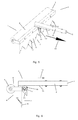
- Fig. 1 is a perspective view of a tool 1 for cleaning a roof or a part of a roof.
- the tool 1 comprises a handle part 2 having a portion 3 for attaching a shaft, e.g. a telescopic shaft, to the handle part 2.
- the tool 1 further comprises a tool head 4 attached to the handle part 2.
- the tool head 4 comprises an advancing portion 5 being provided with a roller 6 and a cleaning portion 7 being provided with a profiled scraper 8.
- Fig. 1 the tool 1 is shown in the first state, i.e. the advancing portion 5, and thereby the roller 6, is oriented in a substantially downwards direction.
- the roller 6 is arranged in abutment with the roof, and the tool head 4 can easily be advanced along the roof by means of the roller 6, as long as the tool head 4 is moved in the direction indicated by arrow 9.
- the tool head 4 is moved in a reverse direction the tool head 4 is shifted to the second state. This will be described in further detail below.
- the scraper 8 is provided with ten distance portions 10 arranged along an edge of the scraper 8.
- the distance portions 10 are made from a material which is softer than the material of the scraper 10. The function of the distance portions 10 will be described further below.
- Fig. 2 is a side view of the tool 1 of Fig. 1 .
- the tool head 4 is moved in the direction indicated by arrow 9 the tool head 4 is caused to rotate about pivot 11 in the direction indicated by arrow 12 until abutment portion 13 abuts plate 14.
- abutment portion 13 abuts plate 14.
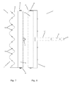
- Fig. 3 is a front view of the tool 1 of Fig. 1 .
- the roller 6 is clearly visible.
- Fig. 4 is a top view of the tool of Fig. 1 .
- the scraper 8 is clearly visible.
- Fig. 5 is a perspective view of the tool 1 of Fig. 1 .
- the tool head 4 is shown in the second state, i.e. the scraper 8 is oriented in a substantially downwards direction, i.e. in the direction in which the roller 6 was oriented in Fig. 1 .
- the scraper 8 can be arranged in abutment with a roof to be cleaned.
- the scraper 8 can be used for cleaning the roof in a scraping operation, as long as the tool head 4 is moved along the direction indicated by arrow 15.
- the scraper 8 has a profiled edge which matches a waved roof profile.
- the distance portions 10 are arranged in such a manner they provide an interface between the scraper 8 and the roof, thereby preventing the actual edge of the scraper 8 from contacting the roof during cleaning. Since the distance portions 10 are made from a material which is softer than the material of the scraper, this allows the scraper 8 to be used on asbestos containing roofs.
- Fig. 6 is a side view of the tool 1 of Fig. 5 . Comparing Fig. 6 and Fig. 2 it is clear that the tool head 4 has been moved to the second state, and that the scraper 8 is oriented in a substantially downwards direction.
- Fig. 7 is a front view of the tool 1 of Fig. 5 .
- the scraper 8 is clearly visible.
- Fig. 8 is a top view of the tool of Fig. 5 .
- the roller 6 is clearly visible.
- Fig. 9 is a perspective view of the tool 1 of Figs. 1 and 5 .
- the roller 6 has been detached from the advancing portion 5.
- a runner 17 and a set of wheels 18 have been shown, thereby illustrating that any one of the roller 6, the runner 17 and the set of wheels 18 may be mounted on the advancing portion 5, depending on the kind of roof to be cleaned, the kind of cleaning operation to be performed, and/or any other relevant circumstances.
- Fig. 10 is a perspective view of the tool 1 of Figs. 1 and 5 .
- the scraper 8 has been detached from the cleaning portion 7.
- a broom 19 is shows, thereby illustrating that the scraper 8 as well as the broom 19 may be mounted on the cleaning portion 7.
- an appropriate tool can be selected, depending on the kind of cleaning operation it is desired or necessary to perform.
- the scraper 8 can be mounted on the cleaning portion 7.
- a sweeping operation is required, e.g.
- the broom 19 can be mounted on the cleaning portion 7. Accordingly, a very flexible tool 1 has been provided.
- the broom 19 is provided with a profiled edge, and it thereby matches a profiled roof. Accordingly, it is possible to perform sweeping operations which clean the 'valleys' of such a roof in a proper manner.
- Fig. 11 illustrates operation of the tool 1 of Figs. 1 and 5 .
- a person 20 is shown operating the tool 1 which is arranged on a roof 21 of a house 22.
- the tool 1 is provided with a telescopic shaft 23 allowing the person 20 to operate the tool 1 from the ground.
- the tool head 4 of the tool 1 is in its first state, i.e. the roller 6 faces the roof 21. In this position the tool 1 can easily be advanced towards the ridge 24 of the roof 21, i.e. in the direction indicated by arrow 25.
- the person 20 pulls the tool 1 in the direction indicated by arrow 26.
- this causes the tool head 4 to shift to its second position, where the scraper 8 is oriented towards the roof 21.
- the scraper 8 is caused to scrape across the roof 21, thereby scraping any undesired elements or items away from the roof 21.
Landscapes
- Engineering & Computer Science (AREA)
- Architecture (AREA)
- Civil Engineering (AREA)
- Structural Engineering (AREA)
- Cleaning In General (AREA)
Abstract
A tool (1) for cleaning at least part of a roof (21), the tool (1) comprising a handle part (2) and a tool head (4). The tool head (4) comprises an advancing portion (5) adapted to provide easy advancement of the tool head (4) along a roof part to be cleaned, and a cleaning portion (7) adapted to perform cleaning operations on a roof part. The tool head (4) is shiftable between a first state and a second state. In the first state the advancing portion (5) is oriented in a predefined direction, preferably towards a roof (21), and the tool (1) is adapted to advance the tool head (4) along a roof part. In n the second state the cleaning portion (7) is oriented in said predefined direction, and the tool (1) is adapted to perform cleaning operations on a roof part.
Since the tool head (4) is shiftable between the two states it is easy to advance the tool head (4) as well as to perform relevant cleaning operations. The tool (1) may be operated from a ground position.
Description
- The present invention relates to a tool for cleaning a roof or a part of a roof, in particular an inclining part of a roof. More particularly, the present invention relates to a tool which can be used for cleaning a roof or a part of a roof in an easy manner and while the operator is positioned on the ground.
- It is sometimes desirable to clean a roof or a part of a roof. This is, e.g., the case when leaves or needles from pines or firs aggregate on the roof, when snow is built up on the roof, or when moss grows on the roof. Such unwanted elements must be removed, e.g. by brushing, sweeping, scraping or spraying, in order to protect the roof.
- In some cases it is necessary that the person performing the cleaning of the roof climbs the roof or at least a ladder. This is a disadvantage, since it introduces the risk of injuries or fatalities to the person. Furthermore, there is an upper limit to the time interval a person is allowed to work on a roof or a ladder. Finally, cleaning a roof in this manner is often very time consuming.
- Attempts to address this problem have previously been made. Thus,
US 2002/0190145 discloses a roof cleaning system including a telescoping tube fluidly connectable to a hose of a pump, a plurality of nozzles fluidly connected to the telescoping tube, and a pair of wheels for movably supporting the device. It is thereby possible to roll the system across the roof by means of the wheels while applying water to the roof via the nozzles. The operator can remain on the ground, due to the telescoping tube. - It is an object of the invention to provide a tool for cleaning at least part of a roof, the tool being easier to operate than similar prior art tools.
- It is a further object of the invention to provide a tool for cleaning at least part of a roof, the tool allowing reduction of the time consumption of cleaning operations as compared to similar prior art tools.
- It is an even further object of the invention to provide a tool for cleaning at least part of a roof, which is less strenuous to operate than similar prior art tools.
- According to the invention the above and other objects are fulfilled by providing a tool for cleaning at least part of a roof, the tool comprising a handle part and a tool head, said tool head comprising
- an advancing portion adapted to provide easy advancement of the tool head along a roof part to be cleaned, and
- a cleaning portion adapted to perform cleaning operations on a roof part,
- The tool may be used for cleaning an entire roof, or it may be used selectively to clean only a part of a roof, e.g. a part onto which moss is growing.
- The handle part may be a part which is adapted to be held directly by an operator during operation of the tool. Alternatively, the handle part may be connectable to such a part. In this case the handle part may advantageously be connectable to an extension shaft, e.g. in the form of a telescopic shaft. This will be described further below.
- The tool head comprises an advancing portion and a cleaning portion. The advancing portion is adapted to provide easy advancement of the tool head along a roof part to be cleaned. Accordingly, the tool head can easily be moved on the roof when cleaning operations are not performed, and it is thereby easy to move the tool head between areas of the roof which need to be cleaned.
- The cleaning portion is adapted to perform cleaning operations on a roof part. The cleaning operations may, e.g., be in the form of brushing or sweeping the roof, applying liquid, such as water, disinfectant, cleaning material, etc. to the roof, scraping moss off the roof, etc. Accordingly, the cleaning portion is used during performance of cleaning operations of the roof.
- The tool head is shiftable between a first state and a second state. In the first state the advancing portion is oriented in a predefined direction, preferably towards a roof part to be cleaned, and in the second state the cleaning portion is oriented in the predefined direction. When the tool head is in the first state it is adapted to advance the tool head along a roof part, and when the tool head is in the second state it is adapted to perform cleaning operations on a roof part. Accordingly, the tool head is shiftable between a state in which is can be easily advanced along the roof and a state in which cleaning operations can be performed. This makes it easy to operate the tool, since it is possible to move the tool along the roof while selectively choosing whether the tool head should be used for cleaning or it should merely be moved to the next area needing cleaning. For instance, it is possible to advance the tool head in an upwards direction towards the roof ridge and perform cleaning operation in a downwards direction towards the gutter of the roof. Furthermore, this lowers the time required to clean a specific area of a roof, and makes it less strenuous for the operator to perform the cleaning. Finally, the tool head only has to be lifted to a lower part of the roof, near the gutter of the roof, and the rest of the roof can then be reached by moving the tool head using the advancing portion.
- The cleaning portion may comprise means for detachably attaching a cleaning module, and an attached cleaning module may define a kind of cleaning operation to be performed by the tool. According to this embodiment, the cleaning module can be removed or replaced. Preferably, two or more cleaning modules may selectively be attached to the cleaning portion via the attaching means. In this case it is possible to select a cleaning module corresponding to a cleaning operation to be performed. For instance, it may be possible to choose between a broom, a brush and a scraper, depending on which kind of cleaning operation it is desired to perform. Alternatively or additionally, it may be possible to choose between cleaning modules of various shape, size or material, depending on the shape or material of the roof to be cleaned.
- The cleaning module may be selected from the group consisting of brooms, brushes, scrapers, nozzles and liquid applicators.
- Brooms may advantageously be used for sweeping a roof, e.g. in order to remove leaves or needles from pines or firs from the roof.
- Brushes may advantageously be used for removing unwanted elements which stick more firmly to the roof, and therefore need brushing in order to be removed. The brushing operation may be performed manually by the operator moving the entire tool. Alternatively, the brush may be mounted in a movable manner, e.g. being able to perform rotational or reciprocal movements with respect to the tool head. A brush may advantageously be combined with one or more applicators supplying water, possibly mixed with cleaning material, disinfectant or the like.
- Scrapers may advantageously be used for removing unwanted growth on the roof, notably moss growth. The scraper is preferably made from a relatively stiff material, e.g. a metal, such as aluminium or stainless steel. As an alternative, the scraper may be made from a plastic material, or from a synthetic fibre material, such as nylon. This is, e.g., an advantage if it is desired to use the scraper on an asbestos containing roof, in which case legislation prevents the use of metal tools due to the risk of damaging the roof and releasing asbestos.
- As another alternative, a metal scraper may be provided with roof interfacing parts made from a softer material, such as plastic, nylon or rubber. In this case the entire scraper may be coated with the softer material, an edge of the scraper may be coated with the softer material, or an edge of the scraper may be provided with distance parts made from the softer material, the distance parts being arranged to abut the roof while preventing the metal edge from abutting the roof.
- Nozzles may be in the form of ordinary nozzles, such as nozzles delivering liquid which is not pressurized or at a low pressure, and/or in the form of nozzles being capable of delivering a liquid under pressure, e.g. for high pressure washing of the roof.
- Liquid applicators may advantageously be used for providing liquid to the roof. Examples of suitable liquids are water, cleaning material, such as soap, disinfectant, pesticide for inhibiting growth of algae or moss, and insecticide. The liquid applicator may be in the form of one or more nozzles or openings. Alternatively, it may be in the form of a soft roller, similar to a paint roller, having a liquid supply in an interior part thereof, and allowing the liquid to penetrate through the soft part from the interior part.
- The cleaning portion may comprise an interface having a shape which matches a profile of the roof part to be cleaned. I n the case that the cleaning portion is adapted to carry a cleaning module as described above, the interface preferably forms part of the cleaning module. In the case that the roof to be cleaned is a wavy roof, e.g. a roof having profiled roof plates, the interface of the cleaning portion preferably has a corresponding shape. Thereby it can be ensured that the 'valleys' of the roof are properly cleaned.
- As an alternative, the cleaning portion may have a substantially straight or linear interface, regardless of the profile of the roof to be cleaned.
- The tool head may be automatically shifted between the first state and the second state in response to a change of direction of movement of the tool head.
- According to this embodiment, the tool is particularly easy to operate, since a simple change in direction of movement causes a desired shift between the two states. According to a preferred embodiment the tool head is in the first state when the tool head is moved upwards and away from the operator, i.e. towards the ridge of the roof, and the tool head is shifted to the second state when this movement is reversed, i.e. when the tool head is moved in a downwards direction towards the gutter of the roof and towards the operator. In this case it is easy to move the tool head when the force of gravity acts against the movement, and the cleaning operation is performed with the help of the force of gravity. Furthermore, it is ensured that any dirt or the like removed from the roof during the cleaning is collected near the gutter or is pushed off the roof, rather than being collected near the ridge of the roof. Thereby such dirt can easily be removed after the cleaning of the roof has been completed.
- As an alternative, the tool head may be manually shiftable between the first state and the second state, e.g. by pushing a button, pulling a wire or operating a handle.
- The predefined direction may advantageously be a direction facing a roof part to be cleaned during normal operation of the tool. In this case the advancing portion faces the roof when the tool head is in the first state, and the cleaning portion faces the roof when the tool head is in the second state. Preferably, the advancing portion/the cleaning portion abuts the roof when the tool head is in the first/second state, respectively.
- The advancing portion may comprise at least one roller. According to this embodiment the tool head is rolled along the roof by means of the roller(s) when the tool head is in the first state. This is, e.g., an advantage when the roof to be cleaned has a wavy profile, because the roller in this case is able to roll along the 'hills' of the roof. Thereby it is possible to move the tool head transversely to waves of the roof profile, thereby making it easier to reach various areas of the roof, and accordingly making it easier to clean the entire roof. For instance, the tool may be operated in such a manner that it is moved to the ridge of the roof at a desired position along the ridge. Then the tool head may be shifted to the second state and the tool head may be pulled away from the ridge and towards the gutter while performing an appropriate cleaning operation. This movement is preferably performed along the profile of the roof. Subsequently, the tool head is once again shifted to the first state and the tool head can be returned to a position near the ridge. This movement is preferably performed partly transversely to the profile of the roof, thereby allowing a subsequent cleaning operation to take place in a different area of the roof.
- As an alternative to one or more rollers, the advancing portion may comprise one or more wheels, one or more runners, one or more smooth surfaces and/or any other suitable means adapted to facilitate movement of the tool head along a roof. Runners may advantageously be used in the case that snow has built up on the roof. The advancing portion may comprise an attachment portion for detachably attaching roller(s), wheel(s), runner(s), etc., e.g. in such a manner that a suitable device can be chosen depending on the circumstances.
- The handle part may comprise or be connectable to a telescopic shaft. According to this embodiment, the tool can easily be operated from the ground.
- The invention will now be described in further detail with reference to the accompanying drawings in which
-
Fig. 1 is a perspective view of a tool according to an embodiment of the invention shown in the first state, -
Fig. 2 is a side view of the tool ofFig. 1 in the first state, -
Fig. 3 is a front view of the tool ofFig. 1 in the first state, -
Fig. 4 is a top view of the tool ofFig. 1 in the first state, -
Fig. 5 is a perspective view of the tool ofFig. 1 shown in the second state, -
Fig. 6 is a side view of the tool ofFig. 5 in the second state, -
Fig. 7 is a front view of the tool ofFig. 5 in the second state, -
Fig. 8 is a top view of the tool ofFig. 5 in the second state, -
Fig. 9 is a perspective view of the tool ofFigs. 1 and5 , illustrating various advancing portions, -
Fig. 10 is a perspective view of the tool ofFigs. 1 and5 , illustrating various cleaning modules to be attached to the cleaning portion, and -
Fig. 11 illustrates operation of the tool ofFigs. 1 and5 . -
Fig. 1 is a perspective view of atool 1 for cleaning a roof or a part of a roof. Thetool 1 comprises ahandle part 2 having aportion 3 for attaching a shaft, e.g. a telescopic shaft, to thehandle part 2. Thetool 1 further comprises atool head 4 attached to thehandle part 2. Thetool head 4 comprises an advancingportion 5 being provided with aroller 6 and acleaning portion 7 being provided with a profiledscraper 8. - In
Fig. 1 thetool 1 is shown in the first state, i.e. the advancingportion 5, and thereby theroller 6, is oriented in a substantially downwards direction. Thus, when thetool 1 is positioned on a roof, theroller 6 is arranged in abutment with the roof, and thetool head 4 can easily be advanced along the roof by means of theroller 6, as long as thetool head 4 is moved in the direction indicated byarrow 9. When thetool head 4 is moved in a reverse direction thetool head 4 is shifted to the second state. This will be described in further detail below. - The
scraper 8 is provided with tendistance portions 10 arranged along an edge of thescraper 8. Thedistance portions 10 are made from a material which is softer than the material of thescraper 10. The function of thedistance portions 10 will be described further below. -
Fig. 2 is a side view of thetool 1 ofFig. 1 . When thetool head 4 is moved in the direction indicated byarrow 9 thetool head 4 is caused to rotate aboutpivot 11 in the direction indicated byarrow 12 untilabutment portion 13 abutsplate 14. Continued movement of thetool head 4 in the direction indicated byarrow 9 causes thetool head 4 to remain in this position, thereby maintaining thetool head 4 in the first state. -
Fig. 3 is a front view of thetool 1 ofFig. 1 . Theroller 6 is clearly visible. -
Fig. 4 is a top view of the tool ofFig. 1 . Thescraper 8 is clearly visible. -
Fig. 5 is a perspective view of thetool 1 ofFig. 1 . However, inFig. 5 thetool head 4 is shown in the second state, i.e. thescraper 8 is oriented in a substantially downwards direction, i.e. in the direction in which theroller 6 was oriented inFig. 1 . Accordingly, when thetool head 4 is in this state, thescraper 8 can be arranged in abutment with a roof to be cleaned. Thereby thescraper 8 can be used for cleaning the roof in a scraping operation, as long as thetool head 4 is moved along the direction indicated byarrow 15. - The
scraper 8 has a profiled edge which matches a waved roof profile. Thedistance portions 10 are arranged in such a manner they provide an interface between thescraper 8 and the roof, thereby preventing the actual edge of thescraper 8 from contacting the roof during cleaning. Since thedistance portions 10 are made from a material which is softer than the material of the scraper, this allows thescraper 8 to be used on asbestos containing roofs. -
Fig. 6 is a side view of thetool 1 ofFig. 5 . ComparingFig. 6 andFig. 2 it is clear that thetool head 4 has been moved to the second state, and that thescraper 8 is oriented in a substantially downwards direction. - When the
tool head 4 is moved along the direction indicated byarrow 15 thetool head 4 is caused to rotate aboutpivot 11 along the direction indicated byarrow 16 until advancingportion 5 abutsplate 14 as shown inFig. 5 . Continued movement of thetool head 4 in the direction indicated byarrow 15 causes thetool head 4 to remain in this position, thereby maintaining thetool head 4 in the second state. -
Fig. 7 is a front view of thetool 1 ofFig. 5 . Thescraper 8 is clearly visible. -
Fig. 8 is a top view of the tool ofFig. 5 . Theroller 6 is clearly visible. -
Fig. 9 is a perspective view of thetool 1 ofFigs. 1 and5 . InFig. 9 theroller 6 has been detached from the advancingportion 5. Furthermore, arunner 17 and a set ofwheels 18 have been shown, thereby illustrating that any one of theroller 6, therunner 17 and the set ofwheels 18 may be mounted on the advancingportion 5, depending on the kind of roof to be cleaned, the kind of cleaning operation to be performed, and/or any other relevant circumstances. -
Fig. 10 is a perspective view of thetool 1 ofFigs. 1 and5 . InFig. 10 thescraper 8 has been detached from the cleaningportion 7. Furthermore, abroom 19 is shows, thereby illustrating that thescraper 8 as well as thebroom 19 may be mounted on thecleaning portion 7. Accordingly, an appropriate tool can be selected, depending on the kind of cleaning operation it is desired or necessary to perform. Thus, in the case that a scraping operation is required, e.g. in order to remove moss from the roof, thescraper 8 can be mounted on thecleaning portion 7. Similarly, in the case that a sweeping operation is required, e.g. in order to remove leaves or needles from pines or firs, or in order to remove moss which has previously been scraped loose using thescraper 8, thebroom 19 can be mounted on thecleaning portion 7. Accordingly, a veryflexible tool 1 has been provided. Thebroom 19 is provided with a profiled edge, and it thereby matches a profiled roof. Accordingly, it is possible to perform sweeping operations which clean the 'valleys' of such a roof in a proper manner. -
Fig. 11 illustrates operation of thetool 1 ofFigs. 1 and5 . InFig. 11 aperson 20 is shown operating thetool 1 which is arranged on aroof 21 of ahouse 22. Thetool 1 is provided with atelescopic shaft 23 allowing theperson 20 to operate thetool 1 from the ground. Thetool head 4 of thetool 1 is in its first state, i.e. theroller 6 faces theroof 21. In this position thetool 1 can easily be advanced towards theridge 24 of theroof 21, i.e. in the direction indicated byarrow 25. When thetool head 4 reaches a desired position, e.g. at or near theridge 24 of theroof 21 , theperson 20 pulls thetool 1 in the direction indicated byarrow 26. As described above, this causes thetool head 4 to shift to its second position, where thescraper 8 is oriented towards theroof 21. By continuously pulling thetool 1 in the direction indicated byarrow 26 thescraper 8 is caused to scrape across theroof 21, thereby scraping any undesired elements or items away from theroof 21.
Claims (9)
- A tool for cleaning at least part of a roof, the tool comprising a handle part and a tool head, said tool head comprising- an advancing portion adapted to provide easy advancement of the tool head along a roof part to be cleaned, and- a cleaning portion adapted to perform cleaning operations on a roof part,wherein the tool head is shiftable between a first state in which the advancing portion is oriented in a predefined direction and a second state in which the cleaning portion is oriented in said predefined direction, and wherein the tool is adapted to advance the tool head along a roof part when the tool head is in the first state, and the tool is adapted to perform cleaning operations on a roof part when the tool head is in the second state.
- A tool according to claim 1, wherein the cleaning portion comprises means for detachably attaching a cleaning module, and wherein an attached cleaning module defines a kind of cleaning operation to be performed by the tool.
- A tool according to claim 2, wherein two or more cleaning modules may be selectively attached to the cleaning portion via the attaching means.
- A tool according to claim 2 or 3, wherein the cleaning module is selected from the group consisting of brooms, brushes, scrapers, nozzles and liquid applicators.
- A tool according to any of the preceding claims, wherein the cleaning portion comprises an interface having a shape which matches a profile of the roof part to be cleaned.
- A tool according to any of the preceding claims, wherein the tool head is automatically shifted between the first state and the second state in response to a change of direction of movement of the tool head.
- A tool according to any of the preceding claims, wherein the predefined direction is a direction facing a roof part to be cleaned during normal operation of the tool.
- A tool according to any of the preceding claims, wherein the advancing portion comprises at least one roller.
- A tool according to any of the preceding claims, wherein the handle part comprises or is connectable to a telescopic shaft.
Priority Applications (1)
| Application Number | Priority Date | Filing Date | Title |
|---|---|---|---|
| EP08153315A EP2105550A1 (en) | 2008-03-26 | 2008-03-26 | A tool for cleaning at least part of a roof |
Applications Claiming Priority (1)
| Application Number | Priority Date | Filing Date | Title |
|---|---|---|---|
| EP08153315A EP2105550A1 (en) | 2008-03-26 | 2008-03-26 | A tool for cleaning at least part of a roof |
Publications (1)
| Publication Number | Publication Date |
|---|---|
| EP2105550A1 true EP2105550A1 (en) | 2009-09-30 |
Family
ID=39689274
Family Applications (1)
| Application Number | Title | Priority Date | Filing Date |
|---|---|---|---|
| EP08153315A Withdrawn EP2105550A1 (en) | 2008-03-26 | 2008-03-26 | A tool for cleaning at least part of a roof |
Country Status (1)
| Country | Link |
|---|---|
| EP (1) | EP2105550A1 (en) |
Cited By (5)
| Publication number | Priority date | Publication date | Assignee | Title |
|---|---|---|---|---|
| EP2345484A1 (en) | 2010-01-15 | 2011-07-20 | Nilfisk Advance A/S | Cleaning apparatus |
| CN107448019A (en) * | 2017-09-29 | 2017-12-08 | 贵州天鹰钢结构有限公司 | A kind of steel-structure factory building for being easy to cleaning |
| RU197251U1 (en) * | 2019-12-27 | 2020-04-15 | Олег Евгеньевич Смиршин | ROOF CLEANING DEVICE |
| RU197250U1 (en) * | 2019-12-27 | 2020-04-15 | Олег Евгеньевич Смиршин | ROOF CLEANING DEVICE |
| WO2022120726A1 (en) * | 2020-12-07 | 2022-06-16 | 江苏新貌城市建设有限公司 | Leveling apparatus for large-span conical roof for use in old microdistrict renovation |
Citations (5)
| Publication number | Priority date | Publication date | Assignee | Title |
|---|---|---|---|---|
| US3583747A (en) * | 1969-04-24 | 1971-06-08 | Agard L Lambert | Snow removing apparatus |
| US4249767A (en) * | 1979-08-27 | 1981-02-10 | Andreasen Norman H | Portable tools for removing snow from pitched roofs |
| US5524369A (en) * | 1994-10-04 | 1996-06-11 | Phillips; Kent D. | Snow removal device |
| US20020190145A1 (en) | 2001-06-15 | 2002-12-19 | Sheppard Glenn T. | Roof cleaning system |
| DE20301253U1 (en) * | 2003-01-28 | 2003-04-03 | Goldberg, Jürgen, 21220 Seevetal | Cleaning broom comprises basic body with brushes extending from its under side and retainer to which broom handle can be fixed in usage state |
-
2008
- 2008-03-26 EP EP08153315A patent/EP2105550A1/en not_active Withdrawn
Patent Citations (5)
| Publication number | Priority date | Publication date | Assignee | Title |
|---|---|---|---|---|
| US3583747A (en) * | 1969-04-24 | 1971-06-08 | Agard L Lambert | Snow removing apparatus |
| US4249767A (en) * | 1979-08-27 | 1981-02-10 | Andreasen Norman H | Portable tools for removing snow from pitched roofs |
| US5524369A (en) * | 1994-10-04 | 1996-06-11 | Phillips; Kent D. | Snow removal device |
| US20020190145A1 (en) | 2001-06-15 | 2002-12-19 | Sheppard Glenn T. | Roof cleaning system |
| DE20301253U1 (en) * | 2003-01-28 | 2003-04-03 | Goldberg, Jürgen, 21220 Seevetal | Cleaning broom comprises basic body with brushes extending from its under side and retainer to which broom handle can be fixed in usage state |
Cited By (5)
| Publication number | Priority date | Publication date | Assignee | Title |
|---|---|---|---|---|
| EP2345484A1 (en) | 2010-01-15 | 2011-07-20 | Nilfisk Advance A/S | Cleaning apparatus |
| CN107448019A (en) * | 2017-09-29 | 2017-12-08 | 贵州天鹰钢结构有限公司 | A kind of steel-structure factory building for being easy to cleaning |
| RU197251U1 (en) * | 2019-12-27 | 2020-04-15 | Олег Евгеньевич Смиршин | ROOF CLEANING DEVICE |
| RU197250U1 (en) * | 2019-12-27 | 2020-04-15 | Олег Евгеньевич Смиршин | ROOF CLEANING DEVICE |
| WO2022120726A1 (en) * | 2020-12-07 | 2022-06-16 | 江苏新貌城市建设有限公司 | Leveling apparatus for large-span conical roof for use in old microdistrict renovation |
Similar Documents
| Publication | Publication Date | Title |
|---|---|---|
| DE102019213088B3 (en) | Cleaning device, base station and operating method of such a cleaning device | |
| DE60300480T2 (en) | SURFACE TREATMENT DEVICE | |
| JP4697983B2 (en) | Guardrail cleaning and painting equipment | |
| EP2020884B1 (en) | Brush for a scrubbing, sweeping and/or polishing machine and spraying device for the cleaning of several surfaces that are separated from each other by means of grooves and/or joints | |
| WO2018162091A1 (en) | Self-propelled and self-steering floor cleaning device | |
| EP3426124B1 (en) | New cleaning device and method for cleaning | |
| EP2721988B1 (en) | Cleaner head for a cleaning appliance for wet cleaning of floor surfaces | |
| CA2906041C (en) | Roof cleaning processes and associated systems | |
| US9834897B2 (en) | Standing shovel | |
| US6158678A (en) | Apparatus for applying fluids to various types and locations of surfaces | |
| US20180228278A1 (en) | Cleaner | |
| EP3225146B1 (en) | Method for cleaning floors and floor cleaning machine | |
| DE202007011485U1 (en) | Mop washer and wringer system | |
| CN214321050U (en) | Solar panel washs and wipes dry integrative equipment | |
| EP1003944B1 (en) | Device for clearing debris from gutters | |
| US9585465B2 (en) | Device for cleaning an object | |
| EP2817104B1 (en) | Surface cleaning head and flow resistance element for a surface cleaning head | |
| JP3140796U (en) | House cleaning equipment | |
| US20120180237A1 (en) | Hose-Attached Paintbrush-Cleaning Comb and Paint-roller Scraper | |
| US20160355052A1 (en) | Device for cleaning a paint roller | |
| US8104133B2 (en) | Gutter cleaning apparatus | |
| CN111197397A (en) | Portable wall whitewashing machine for building construction | |
| DE102014000593A1 (en) | Apparatus for blasting works | |
| CA3010770C (en) | System and method for manually cleaning an environment of a substance with an oil content and hand tools and their cleaning tools for the system | |
| US9562366B2 (en) | Swimming pool cleaning system |
Legal Events
| Date | Code | Title | Description |
|---|---|---|---|
| PUAI | Public reference made under article 153(3) epc to a published international application that has entered the european phase |
Free format text: ORIGINAL CODE: 0009012 |
|
| AK | Designated contracting states |
Kind code of ref document: A1 Designated state(s): AT BE BG CH CY CZ DE DK EE ES FI FR GB GR HR HU IE IS IT LI LT LU LV MC MT NL NO PL PT RO SE SI SK TR |
|
| AX | Request for extension of the european patent |
Extension state: AL BA MK RS |
|
| AKX | Designation fees paid | ||
| REG | Reference to a national code |
Ref country code: DE Ref legal event code: 8566 |
|
| STAA | Information on the status of an ep patent application or granted ep patent |
Free format text: STATUS: THE APPLICATION IS DEEMED TO BE WITHDRAWN |
|
| 18D | Application deemed to be withdrawn |
Effective date: 20100331 |