EP2105349A1 - A non tractive vehicle for the transport of a long windmill wing - Google Patents
A non tractive vehicle for the transport of a long windmill wing Download PDFInfo
- Publication number
- EP2105349A1 EP2105349A1 EP09009143A EP09009143A EP2105349A1 EP 2105349 A1 EP2105349 A1 EP 2105349A1 EP 09009143 A EP09009143 A EP 09009143A EP 09009143 A EP09009143 A EP 09009143A EP 2105349 A1 EP2105349 A1 EP 2105349A1
- Authority
- EP
- European Patent Office
- Prior art keywords
- vehicle
- windmill wing
- tractive vehicle
- tractive
- wing
- Prior art date
- Legal status (The legal status is an assumption and is not a legal conclusion. Google has not performed a legal analysis and makes no representation as to the accuracy of the status listed.)
- Granted
Links
Images

Classifications
-
- B—PERFORMING OPERATIONS; TRANSPORTING
- B60—VEHICLES IN GENERAL
- B60P—VEHICLES ADAPTED FOR LOAD TRANSPORTATION OR TO TRANSPORT, TO CARRY, OR TO COMPRISE SPECIAL LOADS OR OBJECTS
- B60P3/00—Vehicles adapted to transport, to carry or to comprise special loads or objects
- B60P3/40—Vehicles adapted to transport, to carry or to comprise special loads or objects for carrying long loads, e.g. with separate wheeled load supporting elements
-
- F—MECHANICAL ENGINEERING; LIGHTING; HEATING; WEAPONS; BLASTING
- F03—MACHINES OR ENGINES FOR LIQUIDS; WIND, SPRING, OR WEIGHT MOTORS; PRODUCING MECHANICAL POWER OR A REACTIVE PROPULSIVE THRUST, NOT OTHERWISE PROVIDED FOR
- F03D—WIND MOTORS
- F03D13/00—Assembly, mounting or commissioning of wind motors; Arrangements specially adapted for transporting wind motor components
- F03D13/40—Arrangements or methods specially adapted for transporting wind motor components
-
- Y—GENERAL TAGGING OF NEW TECHNOLOGICAL DEVELOPMENTS; GENERAL TAGGING OF CROSS-SECTIONAL TECHNOLOGIES SPANNING OVER SEVERAL SECTIONS OF THE IPC; TECHNICAL SUBJECTS COVERED BY FORMER USPC CROSS-REFERENCE ART COLLECTIONS [XRACs] AND DIGESTS
- Y02—TECHNOLOGIES OR APPLICATIONS FOR MITIGATION OR ADAPTATION AGAINST CLIMATE CHANGE
- Y02E—REDUCTION OF GREENHOUSE GAS [GHG] EMISSIONS, RELATED TO ENERGY GENERATION, TRANSMISSION OR DISTRIBUTION
- Y02E10/00—Energy generation through renewable energy sources
- Y02E10/70—Wind energy
- Y02E10/72—Wind turbines with rotation axis in wind direction
Definitions
- the invention relates to a non-tractive vehicle for the transport of a long windmill wing, said non-tractive vehicle being a part of a vehicle composed of a tractive vehicle equipped with a hydraulic system to which one end of the windmill wing is secured, and a non-tractive vehicle to which the other end of the windmill wing is secured, said non-tractive vehicle comprising a platform on which a rotatable part is arranged with a carrier arrangement secured on the top.
- Windmill energy in particular has obtained an ever more prominent position in recent years, as it has been developed such that not inconsiderable amounts of energy can be produced by ever more effective windmills.
- windmill wings which have a length of between 80 and 100 metres.
- Such a vehicle may typically have a weight of the order of 35 - 40 tons.
- the total weight is of the order of 53 - 58 tons, which gives a considerable axle load on the vehicle which transports the windmill wing.
- connection profile As the distance of the connection profile to the surface of the ground is very small, it may of course be difficult to manoeuvre the vehicle round corners if road signs or differences in level, e.g., are present at the corners.
- WO 03/057528 A1 discloses a vehicle for the transport of a windmill wing, where the windmill wing is suspended between a tractive and a non-tractive vehicle.
- a windmill wing is configured as a partially flat structure which may have a thickness of 3.5 - 4.5 metres at its thick place at the root of the windmill wing, and a width which may be 4.5 - 5.5 metres at its widest place.
- the suspension according to the WO publication is configured such that the windmill wing may be rotated about its longitudinal axis so that it may assume a "high” as well as a "wide” position, which means that if the windmill wing is to be moved through a viaduct having a height which is smaller than the width of the windmill wing, the windmill wing may be rotated about its longitudinal axis and thus be placed with its faces in a position such that the normal of the faces is perpendicular to the road.
- the windmill wing will hereby assume a position where the distance to the road surface is greatest.
- the dimensions of the windmill which decide how high or how low the lowermost part of the windmill wing may be placed above a road, as the highest level means that the windmill wing must assume the widest position on the road, while the lowest level is achieved when the windmill wing stands up.
- the supporting means on the non-tractive vehicle are configured such that they may be rotated about its longitudinal axis, and about its vertical axis.
- the supporting means are adapted to the profile of the windmill wing.
- an object of the invention is to provide a non-tractive vehicle with effective securing means for the windmill wing, which in cooperation with a tractive vehicle is capable of adjusting the distance between the lowest part of the windmill wing and the surface of the road independently of the orientation of the windmill wing, and in a range which is greater than is possible in the known structure, and such that the distance between the lowest part of the windmill wing and the road surface may be adjusted without changing the position of the windmill wing on the vehicle.
- a non-tractive vehicle of the type defined in the introductory portion of claim 1 characterized in that the carrier arrangement is adjustable in the height and formed as a support which is composed of a plurality of holding profiles, said profiles being secured to the top of the carrier arrangement by a fixing frame.
- the holding profiles are placed inside the fixing frames, and that the fixing frames comprise a transverse rod and a vertical rod.
- the transverse rod is movable in the vertical direction and is fixable to the vertical rod.
- non-tractive vehicle is connected hydraulically and electrically to the tractive vehicle, thereby improving the overall steering of the vehicle.
- the tractive vehicle is provided with a hydraulic system comprising a cylinder housing and a carrier member, which hydraulic system is arranged on a bracket provided on the tractive vehicle, and that the hydraulic system is adapted to raise or lower the windmill wing.
- the hydraulic system is arranged rotatably about an axis perpendicular to the road on which the vehicle is manoeuvred.
- the hydraulic system comprises coupling means in the form of posts for coupling to a holding frame which is mounted at one end of the windmill wing.
- the manufactured windmill wings may hereby rapidly be made ready for transport merely by mounting the holding frame on one end of the windmill wing.
- the numeral 1 generally designates a vehicle which consists of a tractive vehicle 3 and a non-tractive vehicle 5.
- a windmill wing 2 is suspended between the tractive vehicle 3 and the non-tractive vehicle 5, as will be explained below.
- the tractive vehicle 3 and the non-tractive vehicle 5 are connected with each other only via the windmill wing 2 and hydraulic/electrical connections, which are shown at 6.
- the tractive vehicle rotatably mounts a hydraulic system which is formed by a cylinder housing 4 in which a piston on a piston rod 11 may be moved in and out.
- the piston rod is secured to a pivot 10 on a bracket 21 which is fixed between two posts 12, while the cylinder housing 4 is secured to a pivot 14 on a bracket 18 which is in turn connected with a carrier member 15.
- the carrier member 15 is secured at its one end rotatably about a pivot 8 on a bracket 20, resting on a ball turntable on the tractive vehicle.
- the opposite end of the carrier member 15 is connected with a pivot 9 on a holding part 22 which is arranged in extension of the posts 12.
- the two posts 12 are inserted into the holding parts 23, 24 on a holding frame 13 which is secured to the windmill wing 2.
- the hydraulic system operates in the following manner:
- Fig. 5 shows the windmill wing 2 with mounted frame 13 and the holding parts 23, 24 for receiving the posts 12 on the hydraulic system.
- Fig. 5 shows the windmill wing 2 with mounted frame 13 and the holding parts 23, 24 for receiving the posts 12 on the hydraulic system.
- a carrier arrangement 26 is secured on a rotatable part 25 on a platform 28, said carrier arrangement 26 being in the form of a support composed of a plurality of holding profiles (31) which are terminated at the top by fixing frames 27, which may be fixed around the rear end of the windmill wing, in that upper transverse rods 29 may be moved in a vertical direction and be fixed in vertical rods 30.
- the holding profiles (31) comprise an upper profile part (32) and a lower profile part (33), having a surface profile which fits the surface profile of the windmill wing (2).
- the windmill wing is safely secured to the vehicle by the transverse rod (29) which is fixed in the vertical rod (30).
- the fixation between the rods (29,30) has to be unfixed and the transverse rod (29) removed in a vertical direction.
- the wings may be removed and replaced by another wing. If the wing has another surface profile, the holding profiles may easily be replaced by holding profiles which fit the new wing profile.
Abstract
Description
- The invention relates to a non-tractive vehicle for the transport of a long windmill wing, said non-tractive vehicle being a part of a vehicle composed of a tractive vehicle equipped with a hydraulic system to which one end of the windmill wing is secured, and a non-tractive vehicle to which the other end of the windmill wing is secured, said non-tractive vehicle comprising a platform on which a rotatable part is arranged with a carrier arrangement secured on the top.
- In the production of energy in the form of electricity, ever great demands are made by politicians and citizens in general with respect to replacing the fossil fuels with alternative renewable sources of energy, such as biogas systems, wave systems and windmill energy.
- Windmill energy in particular has obtained an ever more prominent position in recent years, as it has been developed such that not inconsiderable amounts of energy can be produced by ever more effective windmills.
- The greater efficiency of the windmills has been achieved technologically on the basis of the development of new materials having mechanical properties which make it possible today to manufacture windmill wings with a length of up to more than 60 metres and with a weight of about 18 tons.
- Within a few years it will presumably be possible to manufacture windmill wings which have a length of between 80 and 100 metres.
- When so large windmill wings are to be transported from the factory to the installation site, long special vehicles have been used till now where the windmill wing has rested on a long metal connection profile which is connected between the tractive part of a vehicle and a wheeled platform at the opposite end of the vehicle.
- Such a vehicle may typically have a weight of the order of 35 - 40 tons. When the weight of the windmill wing is added, the total weight is of the order of 53 - 58 tons, which gives a considerable axle load on the vehicle which transports the windmill wing.
- As the distance of the connection profile to the surface of the ground is very small, it may of course be difficult to manoeuvre the vehicle round corners if road signs or differences in level, e.g., are present at the corners.
-
WO 03/057528 A1 - As will be known, a windmill wing is configured as a partially flat structure which may have a thickness of 3.5 - 4.5 metres at its thick place at the root of the windmill wing, and a width which may be 4.5 - 5.5 metres at its widest place.
- The suspension according to the WO publication is configured such that the windmill wing may be rotated about its longitudinal axis so that it may assume a "high" as well as a "wide" position, which means that if the windmill wing is to be moved through a viaduct having a height which is smaller than the width of the windmill wing, the windmill wing may be rotated about its longitudinal axis and thus be placed with its faces in a position such that the normal of the faces is perpendicular to the road. The windmill wing will hereby assume a position where the distance to the road surface is greatest.
- Thus, in the known structure, it is the dimensions of the windmill which decide how high or how low the lowermost part of the windmill wing may be placed above a road, as the highest level means that the windmill wing must assume the widest position on the road, while the lowest level is achieved when the windmill wing stands up.
- The supporting means on the non-tractive vehicle are configured such that they may be rotated about its longitudinal axis, and about its vertical axis. The supporting means are adapted to the profile of the windmill wing.
- Accordingly, an object of the invention is to provide a non-tractive vehicle with effective securing means for the windmill wing, which in cooperation with a tractive vehicle is capable of adjusting the distance between the lowest part of the windmill wing and the surface of the road independently of the orientation of the windmill wing, and in a range which is greater than is possible in the known structure, and such that the distance between the lowest part of the windmill wing and the road surface may be adjusted without changing the position of the windmill wing on the vehicle.
- The object of the invention is achieved by a non-tractive vehicle of the type defined in the introductory portion of
claim 1, characterized in that the carrier arrangement is adjustable in the height and formed as a support which is composed of a plurality of holding profiles, said profiles being secured to the top of the carrier arrangement by a fixing frame. - Hereby, it is possible to hold the windmill wing between the profiles and secured to the non-tractive vehicle, and to raise or lower the wing to avoid obstacles, such as road signs during transport.
- It is an advantage, as stated in
claim 2, that the holding profiles are placed inside the fixing frames, and that the fixing frames comprise a transverse rod and a vertical rod. - Hereby, it is possible to change the holding profiles and to select the profile which fits the transverse surface profile of the wing.
- It is an advantage, as stated in
claim 3, that the transverse rod is movable in the vertical direction and is fixable to the vertical rod. - Hereby, it is possible to place and to secure the wing between the profiles and to the non-tractive vehicle.
- It is a further advantage, as stated in
claim 4, that the non-tractive vehicle is connected hydraulically and electrically to the tractive vehicle, thereby improving the overall steering of the vehicle. - The tractive vehicle is provided with a hydraulic system comprising a cylinder housing and a carrier member, which hydraulic system is arranged on a bracket provided on the tractive vehicle, and that the hydraulic system is adapted to raise or lower the windmill wing.
- Hereby, it is possible during transport to adjust the height of the distance of the windmill wing from the road surface in a great range, and without it being necessary to rotate the windmill wing about its longitudinal axis, which can generally be a risky operation because of the inevitable forces that are generated during such a rotating movement.
- To improve the manoeuvrability of the vehicle additionally, it is an advantage if, the hydraulic system is arranged rotatably about an axis perpendicular to the road on which the vehicle is manoeuvred.
- For easy coupling of the tractive vehicle to the windmill wing it is an advantage if, the hydraulic system comprises coupling means in the form of posts for coupling to a holding frame which is mounted at one end of the windmill wing. The manufactured windmill wings may hereby rapidly be made ready for transport merely by mounting the holding frame on one end of the windmill wing.
- The invention will now be explained more fully with reference to the drawing, in which
- fig. 1
- shows the vehicle with mounted windmill wing,
- fig. 2
- shows the vehicle of
fig. 1 during turning, - fig. 3
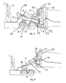
- shows the tractive vehicle where the windmill wing has just been mounted,
- fig. 4
- shows the tractive vehicle of
fig. 3 , but with raised windmill wing made ready for transport, - fig. 5
- shows the root end of a windmill wing with mounted holding frame, while
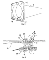
- fig. 6
- shows the non-tractive vehicle with mounted windmill wing fixed in holding profiles.
- In
figs. 1 and 2 , thenumeral 1 generally designates a vehicle which consists of atractive vehicle 3 and anon-tractive vehicle 5. Awindmill wing 2 is suspended between thetractive vehicle 3 and thenon-tractive vehicle 5, as will be explained below. As will be seen, thetractive vehicle 3 and thenon-tractive vehicle 5 are connected with each other only via thewindmill wing 2 and hydraulic/electrical connections, which are shown at 6. - In
fig. 1 , the vehicle is shown on a straight stretch of road, while infig. 2 it is shown during turning, and, as will be seen, thewindmill wing 2 passes over asign 7. - With reference now to
fig. 3 and fig. 4 , it will be explained how the windmill wing is secured to the tractive vehicle. - The tractive vehicle rotatably mounts a hydraulic system which is formed by a
cylinder housing 4 in which a piston on apiston rod 11 may be moved in and out. The piston rod is secured to apivot 10 on a bracket 21 which is fixed between twoposts 12, while thecylinder housing 4 is secured to apivot 14 on a bracket 18 which is in turn connected with acarrier member 15. - Via a bracket 19, the
carrier member 15 is secured at its one end rotatably about apivot 8 on abracket 20, resting on a ball turntable on the tractive vehicle. The opposite end of thecarrier member 15 is connected with a pivot 9 on aholding part 22 which is arranged in extension of theposts 12. - At the bottom, the two
posts 12 are inserted into theholding parts holding frame 13 which is secured to thewindmill wing 2. - The hydraulic system operates in the following manner:
- When pressure is supplied to the
cylinder housing 4 from the position shown infig. 3 , theholding frame 13 with thewindmill wing 2 will be pulled upwards to the position shown infig. 4 , as the carrier member prevents the frame from being moved rearwards during the travel of the piston rod out of thecylinder housing 4. As will be seen, the angle between thecarrier frame 15 and thecylinder housing 4 has become more acute. - When the
windmill wing 2 on theframe 13 is to be lowered, the process is repeated in the reverse order. -
Fig. 5 shows thewindmill wing 2 with mountedframe 13 and theholding parts posts 12 on the hydraulic system. As will be appreciated, it is relatively easy to make a windmill wing ready for transport, since just thebracket 13 is to be mounted on the windmill wing. - With reference now to
fig. 6 , it will be explained how thenon-tractive vehicle 5 is constructed. Acarrier arrangement 26 is secured on arotatable part 25 on a platform 28, saidcarrier arrangement 26 being in the form of a support composed of a plurality of holding profiles (31) which are terminated at the top byfixing frames 27, which may be fixed around the rear end of the windmill wing, in that uppertransverse rods 29 may be moved in a vertical direction and be fixed invertical rods 30. - As will be seen in
fig. 6 , the holding profiles (31) comprise an upper profile part (32) and a lower profile part (33), having a surface profile which fits the surface profile of the windmill wing (2). - As will be seen in
fig. 6 , the windmill wing is safely secured to the vehicle by the transverse rod (29) which is fixed in the vertical rod (30). To release the wing, it is obvious that the fixation between the rods (29,30) has to be unfixed and the transverse rod (29) removed in a vertical direction. - With the fixing frames (27) open, it is obvious that the wings may be removed and replaced by another wing. If the wing has another surface profile, the holding profiles may easily be replaced by holding profiles which fit the new wing profile.
Claims (4)
- A non-tractive vehicle (5) for the transport of a long windmill wing (2), said non-tractive vehicle being a part of a vehicle (1) composed of a tractive vehicle (3) equipped with a hydraulic system to which one end of the windmill wing is secured, and a non-tractive vehicle to which the other end of the windmill wing is secured, said non-tractive vehicle comprising a platform (28) on which a rotatable part (25) is arranged with a carrier arrangement (26) secured on the top, characterized in that the carrier arrangement (26) is adjustable in the height and formed as a support which is composed of a plurality of holding profiles (31), said profiles being secured to the top of the carrier arrangement by a fixing frame (27).
- A non-tractive vehicle according to claim 1, characterized in that the holding profiles (31) comprise an upper profile part (32) and a lower profile part (33), and that the holding profiles are placed inside the fixing frame (27), said fixing frame comprising a transverse rod (29) and a vertical rod (30).
- A non-tractive vehicle according to claims 1-2, characterized in that the transverse rod (29) is movable in the vertical direction and is fixable to the vertical rod (30).
- A non-tractive vehicle according to claims 1-3, characterized in that the non-tractive vehicle is connected hydraulically and electrically to the tractive vehicle, thereby improving the overall steering of the vehicle.
Priority Applications (1)
| Application Number | Priority Date | Filing Date | Title |
|---|---|---|---|
| PL09009143T PL2105349T3 (en) | 2004-06-29 | 2005-06-28 | A non tractive vehicle for the transport of a long windmill wing |
Applications Claiming Priority (2)
| Application Number | Priority Date | Filing Date | Title |
|---|---|---|---|
| DKPA200401026A DK176923B1 (en) | 2004-06-29 | 2004-06-29 | Method for transporting a long wind turbine blade as well as a vehicle for transporting it |
| EP05753544A EP1773621B1 (en) | 2004-06-29 | 2005-06-28 | A method for the transport of a long windmill wing and a vehicle for the transport thereof |
Related Parent Applications (2)
| Application Number | Title | Priority Date | Filing Date |
|---|---|---|---|
| EP05753544A Division EP1773621B1 (en) | 2004-06-29 | 2005-06-28 | A method for the transport of a long windmill wing and a vehicle for the transport thereof |
| EP05753544.5 Division | 2005-06-28 |
Publications (2)
| Publication Number | Publication Date |
|---|---|
| EP2105349A1 true EP2105349A1 (en) | 2009-09-30 |
| EP2105349B1 EP2105349B1 (en) | 2011-02-16 |
Family
ID=32731503
Family Applications (2)
| Application Number | Title | Priority Date | Filing Date |
|---|---|---|---|
| EP09009143A Revoked EP2105349B1 (en) | 2004-06-29 | 2005-06-28 | A non tractive vehicle for the transport of a long windmill wing |
| EP05753544A Active EP1773621B1 (en) | 2004-06-29 | 2005-06-28 | A method for the transport of a long windmill wing and a vehicle for the transport thereof |
Family Applications After (1)
| Application Number | Title | Priority Date | Filing Date |
|---|---|---|---|
| EP05753544A Active EP1773621B1 (en) | 2004-06-29 | 2005-06-28 | A method for the transport of a long windmill wing and a vehicle for the transport thereof |
Country Status (9)
| Country | Link |
|---|---|
| US (1) | US7429156B2 (en) |
| EP (2) | EP2105349B1 (en) |
| AT (2) | ATE441554T1 (en) |
| DE (2) | DE602005016419D1 (en) |
| DK (4) | DK176923B1 (en) |
| ES (2) | ES2330026T3 (en) |
| PL (2) | PL2105349T3 (en) |
| PT (2) | PT2105349E (en) |
| WO (1) | WO2006000230A1 (en) |
Cited By (2)
| Publication number | Priority date | Publication date | Assignee | Title |
|---|---|---|---|---|
| EP3741992A1 (en) | 2019-05-21 | 2020-11-25 | Nordex Energy GmbH | Transport system for a wind energy assembly rotor blade |
| EP4056419A1 (en) * | 2021-03-11 | 2022-09-14 | Scheuerle Fahrzeugfabrik GmbH | Device for holding an end of an elongated object, in particular a self-supporting load, and vehicle for transporting such an elongated object |
Families Citing this family (50)
| Publication number | Priority date | Publication date | Assignee | Title |
|---|---|---|---|---|
| US6833161B2 (en) * | 2002-02-26 | 2004-12-21 | Applied Materials, Inc. | Cyclical deposition of tungsten nitride for metal oxide gate electrode |
| BRPI0405546F1 (en) | 2004-12-10 | 2016-03-22 | Tecsis Tecnologia E Sist S Avançados Ltda | joint development of structures for handling, transporting and storing blades for wind turbine rotors |
| US7704024B2 (en) | 2006-01-31 | 2010-04-27 | General Electric Company | Methods and systems for transporting wind turbine components |
| US20070177954A1 (en) * | 2006-01-31 | 2007-08-02 | General Electric Company | Method and apparatus for containing and/or transporting rotor blades |
| CN101371036B (en) * | 2006-02-13 | 2011-07-27 | 维斯塔斯风力系统有限公司 | Clamping mechanism used for clamping component ends |
| ES2298027B1 (en) * | 2006-04-04 | 2009-07-21 | GAMESA INNOVATION & TECHNOLOGY S.L. | USEFUL FOR THE TRANSPORTATION OF BLADES. |
| DE602007013400D1 (en) * | 2006-06-20 | 2011-05-05 | Vestas Wind Sys As | VEHICLE FOR TRANSPORTING A WIND TURBINE BUCKET, CONTROL SYSTEM AND METHOD FOR TRANSPORTING A WIND TURBINE |
| BRPI0602764B1 (en) | 2006-07-04 | 2016-03-22 | Tecsis Tecnologia E Sist S Avançados Ltda | method and packaging for transporting wind turbine blades |
| WO2008104185A1 (en) * | 2007-02-28 | 2008-09-04 | Vestas Wind Systems A/S | A support system for a wind turbine component, a vehicle transport system for a wind turbine component and a method for operating a support system |
| ES2320959B1 (en) * | 2007-03-30 | 2010-03-12 | GAMESA INNOVATION & TECHNOLOGY, S.L. | SUPPORT FOR THE TRANSPORTATION OF BLADES. |
| DK178765B1 (en) * | 2007-08-17 | 2017-01-09 | Iti Scotland Ltd | A clamping device, one selvfremrykkende climbing device and a method for coupling the same to a tubular structure |
| KR100934204B1 (en) * | 2007-12-20 | 2009-12-29 | 주식회사 효성 | Trailer transport vehicle |
| US8240962B2 (en) * | 2007-12-28 | 2012-08-14 | General Electric Company | Integrated shipping fixture and assembly method for jointed wind turbine blades |
| US7967536B2 (en) * | 2008-05-02 | 2011-06-28 | Gamesa Innovation & Technology, S.L. | Blade transportation |
| CN102123886B (en) * | 2008-08-18 | 2014-03-19 | 西门子公司 | System and method for fixing wind turbine element to vehicle |
| US7591621B1 (en) * | 2008-09-11 | 2009-09-22 | Transportation Technology Services, Inc. | Wind turbine blade transportation system and method |
| WO2010034732A1 (en) * | 2008-09-29 | 2010-04-01 | Vestas Wind Systems A/S | Telescopic vehicle and method for transporting a long object |
| JP4999116B2 (en) * | 2009-03-14 | 2012-08-15 | 栗林機工株式会社 | Inverted support device for wind turbine blades |
| US8096739B1 (en) | 2009-04-08 | 2012-01-17 | Bnsf Railway Company | Method and apparatus for transporting wind turbine blades |
| HUE024438T2 (en) * | 2009-04-09 | 2016-01-28 | Wobben Properties Gmbh | Transport device |
| DE102009017068B4 (en) * | 2009-04-09 | 2013-04-11 | Wobben Properties Gmbh | transport device |
| WO2010125424A1 (en) | 2009-04-27 | 2010-11-04 | Tecsis Tecnologia E Sistemas Avançados Ltda | Interchangeable packing apparatus for aerogenerator blades |
| US8172493B2 (en) * | 2009-05-04 | 2012-05-08 | General Electric Company | Apparatus and method for transporting and aligning wind turbine rotor blade |
| DK2432972T3 (en) * | 2009-05-22 | 2018-08-13 | Vestas Wind Sys As | SYSTEMS AND PROCEDURES FOR TRANSPORTING AND COLLECTING SEGMENTED WINDOWS |
| DE202010000868U1 (en) * | 2009-07-20 | 2010-12-02 | Wader-Wittis Gmbh | Device for transporting and assembling wind turbines |
| US8142120B2 (en) * | 2009-08-11 | 2012-03-27 | Transportation Technology Services, Inc. | Large tower railroad transportation system and method |
| US8500378B1 (en) | 2009-08-11 | 2013-08-06 | Transportation Technology Services, Inc | Large tower railroad transportation system and method |
| US8529174B1 (en) | 2009-08-11 | 2013-09-10 | Transportation Technology Services, Inc. | Large tower railroad transportation system and method |
| US8177462B2 (en) * | 2009-12-07 | 2012-05-15 | General Electric Company | System and method for arranging wind turbine blades |
| US8322954B2 (en) * | 2010-07-26 | 2012-12-04 | General Electric Company | Turbine component transportation system and method |
| ES2751302T3 (en) | 2010-08-12 | 2020-03-31 | Lm Wp Patent Holding As | Transport and storage system for wind turbine blades |
| US9434291B2 (en) | 2010-10-15 | 2016-09-06 | Bnsf Railway Company | Method and apparatus for transporting wind turbine blades |
| US20120090501A1 (en) * | 2010-10-15 | 2012-04-19 | Kelly Thomas P | System and apparatus for multi-modal transportation |
| US20120201636A1 (en) * | 2011-02-07 | 2012-08-09 | Vestas Wind Systems A/S | Transportation device for a wind turbine component and method of using same |
| DE102011113482B4 (en) | 2011-09-13 | 2013-04-18 | Nordex Energy Gmbh | Protective device for a rotor blade of a wind energy plant |
| EP2617990B1 (en) * | 2012-01-17 | 2015-04-15 | ALSTOM Renewable Technologies | Anti-ovalization tool for introduction into a wind turbine blade root and method of reducing ovalization of a wind turbine blade root |
| US8602700B2 (en) | 2012-02-16 | 2013-12-10 | General Electric Company | Shipping fixture and method for transporting rotor blades |
| EP2666669B1 (en) | 2012-05-22 | 2016-06-29 | Siemens Aktiengesellschaft | Transportation of wind turbine blades, in particular along curved roads |
| KR200463113Y1 (en) * | 2012-06-19 | 2012-10-17 | 주식회사 성진풍력 | trailer for transporting wind generator blade |
| DK2705982T4 (en) | 2012-09-06 | 2019-05-13 | Siemens Ag | Transport system for a wind turbine blade |
| KR101422708B1 (en) | 2012-09-21 | 2014-07-23 | 삼성중공업 주식회사 | Truck |
| EP2719578B1 (en) * | 2012-10-15 | 2018-01-03 | Scheuerle Fahrzeugfabrik GmbH | Coupling assembly and a heavy duty transport vehicle with such a coupling assembly |
| US8708625B1 (en) | 2013-03-19 | 2014-04-29 | Transportation Technology Services, Inc. | Wind turbine blade railroad transportation system and method |
| CN105722725B (en) | 2013-09-16 | 2017-09-22 | 维斯塔斯风力系统有限公司 | The transport of wind turbine blade and stacking |
| EP2947311B1 (en) | 2014-05-23 | 2018-12-26 | Siemens Aktiengesellschaft | Blade tip clamp arrangement |
| US10232862B2 (en) * | 2016-01-26 | 2019-03-19 | Bnsf Logistics, Llc | Saddle system for use in the rail transport of large towers |
| EP3542051B1 (en) * | 2016-11-21 | 2021-05-19 | LM Wind Power International Technology II ApS | A method and system for establishing a sectional or modular wind turbine blade and a mobile factory for joining sections of a wind turbine blade |
| ES2915055T3 (en) | 2018-06-20 | 2022-06-20 | Nordex Energy Se & Co Kg | Towing vehicle for transporting a wind turbine rotor blade, moving device of a towing vehicle, transport vehicle and method |
| DE202018106492U1 (en) * | 2018-11-15 | 2019-02-15 | Peter Adams | Vehicle for transporting a long cargo |
| EP4015817A1 (en) * | 2020-12-17 | 2022-06-22 | Nordex Energy Spain, S.A.U. | Wind turbine rotor blade spacer, transportation and storage system for wind turbine rotor blades and related method |
Citations (5)
| Publication number | Priority date | Publication date | Assignee | Title |
|---|---|---|---|---|
| DE2204962A1 (en) * | 1972-02-03 | 1973-08-09 | Fries Gmbh Heinrich De | TRANSPORT DEVICE FOR LARGE CONTAINERS |
| US5017081A (en) * | 1987-06-22 | 1991-05-21 | Helton Jesse D | Truss transportation trailer |
| JP2002059776A (en) * | 2000-08-17 | 2002-02-26 | Nippon Express Co Ltd | Transporting device for cylindrical structured tower for wind power generator |
| WO2003057528A1 (en) | 2002-01-08 | 2003-07-17 | Aloys Wobben | Transport vehicle for a rotor blade of a wind-energy turbine |
| WO2004041589A1 (en) * | 2002-10-30 | 2004-05-21 | Koninklijke Nooteboom Trailers B.V. | Method and device for supporting a self-supporting load an undercarriages |
Family Cites Families (2)
| Publication number | Priority date | Publication date | Assignee | Title |
|---|---|---|---|---|
| US2903274A (en) * | 1957-11-29 | 1959-09-08 | Jr Talbert A Leonard | Propeller carrier |
| US4750785A (en) * | 1987-06-22 | 1988-06-14 | Helton Jesse D | Truss transportation trailer |
-
2004
- 2004-06-29 DK DKPA200401026A patent/DK176923B1/en not_active IP Right Cessation
-
2005
- 2005-06-28 DK DK05753544T patent/DK1773621T3/en active
- 2005-06-28 WO PCT/DK2005/000437 patent/WO2006000230A1/en active Application Filing
- 2005-06-28 AT AT05753544T patent/ATE441554T1/en not_active IP Right Cessation
- 2005-06-28 ES ES05753544T patent/ES2330026T3/en active Active
- 2005-06-28 EP EP09009143A patent/EP2105349B1/en not_active Revoked
- 2005-06-28 US US11/630,274 patent/US7429156B2/en active Active
- 2005-06-28 ES ES09009143T patent/ES2361467T3/en active Active
- 2005-06-28 PL PL09009143T patent/PL2105349T3/en unknown
- 2005-06-28 DE DE602005016419T patent/DE602005016419D1/en active Active
- 2005-06-28 DK DK09009143.0T patent/DK2105349T5/en active
- 2005-06-28 PL PL05753544T patent/PL1773621T3/en unknown
- 2005-06-28 PT PT09009143T patent/PT2105349E/en unknown
- 2005-06-28 EP EP05753544A patent/EP1773621B1/en active Active
- 2005-06-28 PT PT05753544T patent/PT1773621E/en unknown
- 2005-06-28 DE DE602005026469T patent/DE602005026469D1/en active Active
- 2005-06-28 AT AT09009143T patent/ATE498514T1/en not_active IP Right Cessation
-
2009
- 2009-10-07 DK DKBA200900158U patent/DK200900158U4/en active
Patent Citations (5)
| Publication number | Priority date | Publication date | Assignee | Title |
|---|---|---|---|---|
| DE2204962A1 (en) * | 1972-02-03 | 1973-08-09 | Fries Gmbh Heinrich De | TRANSPORT DEVICE FOR LARGE CONTAINERS |
| US5017081A (en) * | 1987-06-22 | 1991-05-21 | Helton Jesse D | Truss transportation trailer |
| JP2002059776A (en) * | 2000-08-17 | 2002-02-26 | Nippon Express Co Ltd | Transporting device for cylindrical structured tower for wind power generator |
| WO2003057528A1 (en) | 2002-01-08 | 2003-07-17 | Aloys Wobben | Transport vehicle for a rotor blade of a wind-energy turbine |
| WO2004041589A1 (en) * | 2002-10-30 | 2004-05-21 | Koninklijke Nooteboom Trailers B.V. | Method and device for supporting a self-supporting load an undercarriages |
Cited By (2)
| Publication number | Priority date | Publication date | Assignee | Title |
|---|---|---|---|---|
| EP3741992A1 (en) | 2019-05-21 | 2020-11-25 | Nordex Energy GmbH | Transport system for a wind energy assembly rotor blade |
| EP4056419A1 (en) * | 2021-03-11 | 2022-09-14 | Scheuerle Fahrzeugfabrik GmbH | Device for holding an end of an elongated object, in particular a self-supporting load, and vehicle for transporting such an elongated object |
Also Published As
| Publication number | Publication date |
|---|---|
| ES2330026T3 (en) | 2009-12-03 |
| US20070248431A1 (en) | 2007-10-25 |
| PL2105349T3 (en) | 2011-09-30 |
| DE602005026469D1 (en) | 2011-03-31 |
| EP2105349B1 (en) | 2011-02-16 |
| WO2006000230A1 (en) | 2006-01-05 |
| PT2105349E (en) | 2011-05-23 |
| DK2105349T5 (en) | 2011-05-09 |
| PL1773621T3 (en) | 2010-02-26 |
| ATE498514T1 (en) | 2011-03-15 |
| DK1773621T3 (en) | 2009-09-28 |
| US7429156B2 (en) | 2008-09-30 |
| ATE441554T1 (en) | 2009-09-15 |
| DK176923B1 (en) | 2010-05-17 |
| DK200401026A (en) | 2004-06-29 |
| DK200900158U4 (en) | 2013-02-08 |
| EP1773621B1 (en) | 2009-09-02 |
| DK2105349T3 (en) | 2011-03-14 |
| PT1773621E (en) | 2009-10-06 |
| DE602005016419D1 (en) | 2009-10-15 |
| EP1773621A1 (en) | 2007-04-18 |
| ES2361467T3 (en) | 2011-06-17 |
Similar Documents
| Publication | Publication Date | Title |
|---|---|---|
| EP2105349B1 (en) | A non tractive vehicle for the transport of a long windmill wing | |
| US20160285412A1 (en) | Truck mounted solar panel system | |
| JP5850344B2 (en) | Stackable tracking solar collector assembly | |
| CN101489830B (en) | A vehicle for transporting a wind turbine blade, a control system and a method for transporting a wind turbine blade | |
| KR101918970B1 (en) | Floating solar power generating system | |
| CN104503470B (en) | A kind of oblique uniaxial tracking bracket of photovoltaic generation | |
| CN102931253A (en) | Solar power generation unit and double-spindle tracking support thereof | |
| CN201504196U (en) | Combined mounting frame for ground solar energy photovoltaic plant | |
| CN206819163U (en) | Photovoltaic generation suspension type solar tracking support system | |
| CN201708736U (en) | Frame structure for solar tracking system | |
| CN210041737U (en) | Photovoltaic tracking system applicable to terrains with different slopes | |
| CN210162158U (en) | Novel ultralow hydraulic trailer | |
| FR2752443A1 (en) | Dual rotor wind generator for use on or off-shore | |
| CN110878542A (en) | Pick up turning device for snow shovel | |
| CN219523705U (en) | Electric car charging pile based on solar energy | |
| CN204836047U (en) | Take photovoltaic support of equipment platform | |
| CN219999280U (en) | Photovoltaic bracket | |
| CN210971331U (en) | Frame that wind-powered electricity generation blade transport vechicle rear portion can translate | |
| CN216644584U (en) | Solar device capable of adjusting gradient | |
| CN220163860U (en) | Mine construction fortune stone car bearing structure | |
| CN217769944U (en) | Variable cross-section photovoltaic support stand | |
| CN207504797U (en) | A kind of liftable translates photovoltaic module structure | |
| CN219976784U (en) | Heliostat structure | |
| CN219386665U (en) | Connection base of photovoltaic bicycle shed | |
| CN207603525U (en) | Photovoltaic system and its stent system |
Legal Events
| Date | Code | Title | Description |
|---|---|---|---|
| PUAI | Public reference made under article 153(3) epc to a published international application that has entered the european phase |
Free format text: ORIGINAL CODE: 0009012 |
|
| AC | Divisional application: reference to earlier application |
Ref document number: 1773621 Country of ref document: EP Kind code of ref document: P |
|
| AK | Designated contracting states |
Kind code of ref document: A1 Designated state(s): AT BE BG CH CY CZ DE DK EE ES FI FR GB GR HU IE IS IT LI LT LU MC NL PL PT RO SE SI SK TR |
|
| RIN1 | Information on inventor provided before grant (corrected) |
Inventor name: JENSEN, JORGEN, EGESKOV |
|
| 17P | Request for examination filed |
Effective date: 20091124 |
|
| 17Q | First examination report despatched |
Effective date: 20100331 |
|
| GRAP | Despatch of communication of intention to grant a patent |
Free format text: ORIGINAL CODE: EPIDOSNIGR1 |
|
| RIC1 | Information provided on ipc code assigned before grant |
Ipc: F03D 1/00 20060101ALI20101026BHEP Ipc: B60P 3/40 20060101AFI20101026BHEP |
|
| GRAS | Grant fee paid |
Free format text: ORIGINAL CODE: EPIDOSNIGR3 |
|
| GRAA | (expected) grant |
Free format text: ORIGINAL CODE: 0009210 |
|
| AC | Divisional application: reference to earlier application |
Ref document number: 1773621 Country of ref document: EP Kind code of ref document: P |
|
| AK | Designated contracting states |
Kind code of ref document: B1 Designated state(s): AT BE BG CH CY CZ DE DK EE ES FI FR GB GR HU IE IS IT LI LT LU MC NL PL PT RO SE SI SK TR |
|
| AX | Request for extension of the european patent |
Extension state: AL BA HR LV MK YU |
|
| REG | Reference to a national code |
Ref country code: GB Ref legal event code: FG4D |
|
| REG | Reference to a national code |
Ref country code: CH Ref legal event code: EP |
|
| REG | Reference to a national code |
Ref country code: DK Ref legal event code: T3 |
|
| REG | Reference to a national code |
Ref country code: IE Ref legal event code: FG4D |
|
| REF | Corresponds to: |
Ref document number: 602005026469 Country of ref document: DE Date of ref document: 20110331 Kind code of ref document: P |
|
| REG | Reference to a national code |
Ref country code: DE Ref legal event code: R096 Ref document number: 602005026469 Country of ref document: DE Effective date: 20110331 |
|
| REG | Reference to a national code |
Ref country code: DK Ref legal event code: T5 |
|
| REG | Reference to a national code |
Ref country code: NL Ref legal event code: T3 |
|
| REG | Reference to a national code |
Ref country code: PT Ref legal event code: SC4A Free format text: AVAILABILITY OF NATIONAL TRANSLATION Effective date: 20110512 |
|
| REG | Reference to a national code |
Ref country code: SE Ref legal event code: TRGR |
|
| REG | Reference to a national code |
Ref country code: ES Ref legal event code: FG2A Ref document number: 2361467 Country of ref document: ES Kind code of ref document: T3 Effective date: 20110617 |
|
| REG | Reference to a national code |
Ref country code: GR Ref legal event code: EP Ref document number: 20110401117 Country of ref document: GR Effective date: 20110614 |
|
| PG25 | Lapsed in a contracting state [announced via postgrant information from national office to epo] |
Ref country code: AT Free format text: LAPSE BECAUSE OF FAILURE TO SUBMIT A TRANSLATION OF THE DESCRIPTION OR TO PAY THE FEE WITHIN THE PRESCRIBED TIME-LIMIT Effective date: 20110216 Ref country code: SI Free format text: LAPSE BECAUSE OF FAILURE TO SUBMIT A TRANSLATION OF THE DESCRIPTION OR TO PAY THE FEE WITHIN THE PRESCRIBED TIME-LIMIT Effective date: 20110216 Ref country code: CY Free format text: LAPSE BECAUSE OF FAILURE TO SUBMIT A TRANSLATION OF THE DESCRIPTION OR TO PAY THE FEE WITHIN THE PRESCRIBED TIME-LIMIT Effective date: 20110216 Ref country code: BG Free format text: LAPSE BECAUSE OF FAILURE TO SUBMIT A TRANSLATION OF THE DESCRIPTION OR TO PAY THE FEE WITHIN THE PRESCRIBED TIME-LIMIT Effective date: 20110516 |
|
| REG | Reference to a national code |
Ref country code: PL Ref legal event code: T3 |
|
| PLBI | Opposition filed |
Free format text: ORIGINAL CODE: 0009260 |
|
| PG25 | Lapsed in a contracting state [announced via postgrant information from national office to epo] |
Ref country code: SK Free format text: LAPSE BECAUSE OF FAILURE TO SUBMIT A TRANSLATION OF THE DESCRIPTION OR TO PAY THE FEE WITHIN THE PRESCRIBED TIME-LIMIT Effective date: 20110216 Ref country code: CZ Free format text: LAPSE BECAUSE OF FAILURE TO SUBMIT A TRANSLATION OF THE DESCRIPTION OR TO PAY THE FEE WITHIN THE PRESCRIBED TIME-LIMIT Effective date: 20110216 Ref country code: RO Free format text: LAPSE BECAUSE OF FAILURE TO SUBMIT A TRANSLATION OF THE DESCRIPTION OR TO PAY THE FEE WITHIN THE PRESCRIBED TIME-LIMIT Effective date: 20110216 |
|
| PLAX | Notice of opposition and request to file observation + time limit sent |
Free format text: ORIGINAL CODE: EPIDOSNOBS2 |
|
| 26 | Opposition filed |
Opponent name: NORDEX ENERGY GMBH Effective date: 20111116 Opponent name: GOLDHOFER AKTIENGESELLSCHAFT Effective date: 20111115 |
|
| REG | Reference to a national code |
Ref country code: CH Ref legal event code: PL |
|
| REG | Reference to a national code |
Ref country code: DE Ref legal event code: R026 Ref document number: 602005026469 Country of ref document: DE Effective date: 20111115 |
|
| PLAF | Information modified related to communication of a notice of opposition and request to file observations + time limit |
Free format text: ORIGINAL CODE: EPIDOSCOBS2 |
|
| PG25 | Lapsed in a contracting state [announced via postgrant information from national office to epo] |
Ref country code: CH Free format text: LAPSE BECAUSE OF NON-PAYMENT OF DUE FEES Effective date: 20110630 Ref country code: LI Free format text: LAPSE BECAUSE OF NON-PAYMENT OF DUE FEES Effective date: 20110630 |
|
| PLBB | Reply of patent proprietor to notice(s) of opposition received |
Free format text: ORIGINAL CODE: EPIDOSNOBS3 |
|
| PGFP | Annual fee paid to national office [announced via postgrant information from national office to epo] |
Ref country code: DE Payment date: 20120620 Year of fee payment: 8 Ref country code: IE Payment date: 20120612 Year of fee payment: 8 Ref country code: LT Payment date: 20120516 Year of fee payment: 8 Ref country code: EE Payment date: 20120517 Year of fee payment: 8 Ref country code: NL Payment date: 20120614 Year of fee payment: 8 Ref country code: DK Payment date: 20120612 Year of fee payment: 8 |
|
| PGFP | Annual fee paid to national office [announced via postgrant information from national office to epo] |
Ref country code: FI Payment date: 20120612 Year of fee payment: 8 Ref country code: GR Payment date: 20120521 Year of fee payment: 8 Ref country code: PL Payment date: 20120416 Year of fee payment: 8 Ref country code: SE Payment date: 20120612 Year of fee payment: 8 Ref country code: FR Payment date: 20120619 Year of fee payment: 8 Ref country code: GB Payment date: 20120627 Year of fee payment: 8 |
|
| PGFP | Annual fee paid to national office [announced via postgrant information from national office to epo] |
Ref country code: IT Payment date: 20120512 Year of fee payment: 8 |
|
| PGFP | Annual fee paid to national office [announced via postgrant information from national office to epo] |
Ref country code: BE Payment date: 20120620 Year of fee payment: 8 |
|
| PGFP | Annual fee paid to national office [announced via postgrant information from national office to epo] |
Ref country code: ES Payment date: 20120726 Year of fee payment: 8 |
|
| PGFP | Annual fee paid to national office [announced via postgrant information from national office to epo] |
Ref country code: PT Payment date: 20120516 Year of fee payment: 8 |
|
| REG | Reference to a national code |
Ref country code: DE Ref legal event code: R064 Ref document number: 602005026469 Country of ref document: DE Ref country code: DE Ref legal event code: R103 Ref document number: 602005026469 Country of ref document: DE |
|
| RDAF | Communication despatched that patent is revoked |
Free format text: ORIGINAL CODE: EPIDOSNREV1 |
|
| PG25 | Lapsed in a contracting state [announced via postgrant information from national office to epo] |
Ref country code: MC Free format text: LAPSE BECAUSE OF NON-PAYMENT OF DUE FEES Effective date: 20110630 |
|
| PG25 | Lapsed in a contracting state [announced via postgrant information from national office to epo] |
Ref country code: LU Free format text: LAPSE BECAUSE OF NON-PAYMENT OF DUE FEES Effective date: 20110628 |
|
| RDAG | Patent revoked |
Free format text: ORIGINAL CODE: 0009271 |
|
| STAA | Information on the status of an ep patent application or granted ep patent |
Free format text: STATUS: PATENT REVOKED |
|
| 27W | Patent revoked |
Effective date: 20130207 |
|
| GBPR | Gb: patent revoked under art. 102 of the ep convention designating the uk as contracting state |
Effective date: 20130207 |
|
| REG | Reference to a national code |
Ref country code: PT Ref legal event code: MP4A Effective date: 20130717 |
|
| PG25 | Lapsed in a contracting state [announced via postgrant information from national office to epo] |
Ref country code: IS Free format text: LAPSE BECAUSE OF FAILURE TO SUBMIT A TRANSLATION OF THE DESCRIPTION OR TO PAY THE FEE WITHIN THE PRESCRIBED TIME-LIMIT Effective date: 20110216 |
|
| REG | Reference to a national code |
Ref country code: DE Ref legal event code: R107 Ref document number: 602005026469 Country of ref document: DE Effective date: 20130912 |
|
| PG25 | Lapsed in a contracting state [announced via postgrant information from national office to epo] |
Ref country code: TR Free format text: LAPSE BECAUSE OF FAILURE TO SUBMIT A TRANSLATION OF THE DESCRIPTION OR TO PAY THE FEE WITHIN THE PRESCRIBED TIME-LIMIT Effective date: 20110216 |
|
| REG | Reference to a national code |
Ref country code: EE Ref legal event code: MF4A Ref document number: E005481 Country of ref document: EE Effective date: 20130716 |
|
| PG25 | Lapsed in a contracting state [announced via postgrant information from national office to epo] |
Ref country code: HU Free format text: LAPSE BECAUSE OF FAILURE TO SUBMIT A TRANSLATION OF THE DESCRIPTION OR TO PAY THE FEE WITHIN THE PRESCRIBED TIME-LIMIT Effective date: 20110216 |
|
| REG | Reference to a national code |
Ref country code: SE Ref legal event code: ECNC |
|
| REG | Reference to a national code |
Ref country code: SE Ref legal event code: ECNC |
|
| REG | Reference to a national code |
Ref country code: SE Ref legal event code: ECNC |