EP2105342B1 - Industrial truck with an electrical drive - Google Patents
Industrial truck with an electrical drive Download PDFInfo
- Publication number
- EP2105342B1 EP2105342B1 EP09001017.4A EP09001017A EP2105342B1 EP 2105342 B1 EP2105342 B1 EP 2105342B1 EP 09001017 A EP09001017 A EP 09001017A EP 2105342 B1 EP2105342 B1 EP 2105342B1
- Authority
- EP
- European Patent Office
- Prior art keywords
- energy storage
- industrial truck
- storage device
- drive
- battery
- Prior art date
- Legal status (The legal status is an assumption and is not a legal conclusion. Google has not performed a legal analysis and makes no representation as to the accuracy of the status listed.)
- Expired - Fee Related
Links
Images

Classifications
-
- B—PERFORMING OPERATIONS; TRANSPORTING
- B60—VEHICLES IN GENERAL
- B60L—PROPULSION OF ELECTRICALLY-PROPELLED VEHICLES; SUPPLYING ELECTRIC POWER FOR AUXILIARY EQUIPMENT OF ELECTRICALLY-PROPELLED VEHICLES; ELECTRODYNAMIC BRAKE SYSTEMS FOR VEHICLES IN GENERAL; MAGNETIC SUSPENSION OR LEVITATION FOR VEHICLES; MONITORING OPERATING VARIABLES OF ELECTRICALLY-PROPELLED VEHICLES; ELECTRIC SAFETY DEVICES FOR ELECTRICALLY-PROPELLED VEHICLES
- B60L15/00—Methods, circuits, or devices for controlling the traction-motor speed of electrically-propelled vehicles
- B60L15/20—Methods, circuits, or devices for controlling the traction-motor speed of electrically-propelled vehicles for control of the vehicle or its driving motor to achieve a desired performance, e.g. speed, torque, programmed variation of speed
- B60L15/2009—Methods, circuits, or devices for controlling the traction-motor speed of electrically-propelled vehicles for control of the vehicle or its driving motor to achieve a desired performance, e.g. speed, torque, programmed variation of speed for braking
-
- B—PERFORMING OPERATIONS; TRANSPORTING
- B60—VEHICLES IN GENERAL
- B60L—PROPULSION OF ELECTRICALLY-PROPELLED VEHICLES; SUPPLYING ELECTRIC POWER FOR AUXILIARY EQUIPMENT OF ELECTRICALLY-PROPELLED VEHICLES; ELECTRODYNAMIC BRAKE SYSTEMS FOR VEHICLES IN GENERAL; MAGNETIC SUSPENSION OR LEVITATION FOR VEHICLES; MONITORING OPERATING VARIABLES OF ELECTRICALLY-PROPELLED VEHICLES; ELECTRIC SAFETY DEVICES FOR ELECTRICALLY-PROPELLED VEHICLES
- B60L50/00—Electric propulsion with power supplied within the vehicle
- B60L50/40—Electric propulsion with power supplied within the vehicle using propulsion power supplied by capacitors
-
- B—PERFORMING OPERATIONS; TRANSPORTING
- B60—VEHICLES IN GENERAL
- B60L—PROPULSION OF ELECTRICALLY-PROPELLED VEHICLES; SUPPLYING ELECTRIC POWER FOR AUXILIARY EQUIPMENT OF ELECTRICALLY-PROPELLED VEHICLES; ELECTRODYNAMIC BRAKE SYSTEMS FOR VEHICLES IN GENERAL; MAGNETIC SUSPENSION OR LEVITATION FOR VEHICLES; MONITORING OPERATING VARIABLES OF ELECTRICALLY-PROPELLED VEHICLES; ELECTRIC SAFETY DEVICES FOR ELECTRICALLY-PROPELLED VEHICLES
- B60L58/00—Methods or circuit arrangements for monitoring or controlling batteries or fuel cells, specially adapted for electric vehicles
- B60L58/10—Methods or circuit arrangements for monitoring or controlling batteries or fuel cells, specially adapted for electric vehicles for monitoring or controlling batteries
- B60L58/18—Methods or circuit arrangements for monitoring or controlling batteries or fuel cells, specially adapted for electric vehicles for monitoring or controlling batteries of two or more battery modules
- B60L58/20—Methods or circuit arrangements for monitoring or controlling batteries or fuel cells, specially adapted for electric vehicles for monitoring or controlling batteries of two or more battery modules having different nominal voltages
-
- Y—GENERAL TAGGING OF NEW TECHNOLOGICAL DEVELOPMENTS; GENERAL TAGGING OF CROSS-SECTIONAL TECHNOLOGIES SPANNING OVER SEVERAL SECTIONS OF THE IPC; TECHNICAL SUBJECTS COVERED BY FORMER USPC CROSS-REFERENCE ART COLLECTIONS [XRACs] AND DIGESTS
- Y02—TECHNOLOGIES OR APPLICATIONS FOR MITIGATION OR ADAPTATION AGAINST CLIMATE CHANGE
- Y02T—CLIMATE CHANGE MITIGATION TECHNOLOGIES RELATED TO TRANSPORTATION
- Y02T10/00—Road transport of goods or passengers
- Y02T10/60—Other road transportation technologies with climate change mitigation effect
- Y02T10/64—Electric machine technologies in electromobility
-
- Y—GENERAL TAGGING OF NEW TECHNOLOGICAL DEVELOPMENTS; GENERAL TAGGING OF CROSS-SECTIONAL TECHNOLOGIES SPANNING OVER SEVERAL SECTIONS OF THE IPC; TECHNICAL SUBJECTS COVERED BY FORMER USPC CROSS-REFERENCE ART COLLECTIONS [XRACs] AND DIGESTS
- Y02—TECHNOLOGIES OR APPLICATIONS FOR MITIGATION OR ADAPTATION AGAINST CLIMATE CHANGE
- Y02T—CLIMATE CHANGE MITIGATION TECHNOLOGIES RELATED TO TRANSPORTATION
- Y02T10/00—Road transport of goods or passengers
- Y02T10/60—Other road transportation technologies with climate change mitigation effect
- Y02T10/70—Energy storage systems for electromobility, e.g. batteries
-
- Y—GENERAL TAGGING OF NEW TECHNOLOGICAL DEVELOPMENTS; GENERAL TAGGING OF CROSS-SECTIONAL TECHNOLOGIES SPANNING OVER SEVERAL SECTIONS OF THE IPC; TECHNICAL SUBJECTS COVERED BY FORMER USPC CROSS-REFERENCE ART COLLECTIONS [XRACs] AND DIGESTS
- Y02—TECHNOLOGIES OR APPLICATIONS FOR MITIGATION OR ADAPTATION AGAINST CLIMATE CHANGE
- Y02T—CLIMATE CHANGE MITIGATION TECHNOLOGIES RELATED TO TRANSPORTATION
- Y02T10/00—Road transport of goods or passengers
- Y02T10/60—Other road transportation technologies with climate change mitigation effect
- Y02T10/72—Electric energy management in electromobility
Definitions
- the present invention relates to a truck with an electric drive, which is powered by a rechargeable battery. Furthermore, the truck has a control to switch the electric drive in a regenerative mode.
- the electric drive may be an electric traction drive for the industrial truck, but it is also possible to use the invention for electric lifting drives and / or electric steering systems.
- the regenerative electric power is either returned to the battery or directly consumed electrically.
- a DC drive with starting aid for industrial trucks, especially drawbar vehicles in Mitgeh réelle is in EP 0 536 490 A1 described.
- the DC drive with starting aid is designed such that it prevents a rolling back of the vehicle when starting on a slope.
- the invention has for its object to provide an industrial truck with an electric drive, the electrical supply is as durable as possible and stable by a battery.
- the truck according to the invention has an electric drive, which can be powered by a rechargeable battery. Furthermore, the truck is equipped with an electric drive control that can switch the drive to regenerative operation.
- a second energy store is provided, which can be charged in regenerative operation of the drive and can power the drive during motor operation.
- the electrical energy can be obtained, for example, from a braking operation or from other processes, such as the lowering of a load or cornering.
- the regenerative electrical energy obtained is used for a second energy storage, which is recharged in regenerative operation.
- the second energy store can be switched to the drive in such a way that the drive is additionally fed by the second energy store.
- the battery is spared in a special way.
- the battery is not recharged directly in regenerative operation, so that the battery can be subjected to controlled charging and discharging cycles.
- the further energy storage also offers the advantage that it can be connected to the supply of the electric drive and so the battery is protected, especially with a large power extraction.
- the further energy storage is charged to a charging voltage which is greater than or equal to the battery voltage.
- Charging the second energy store to a particularly high voltage offers the advantage that when the second energy store is connected, the drive can be supplied with a sufficiently high voltage, even if the voltage from the battery is already decreasing.
- the electric drive is fed by the second energy storage together with the battery in predetermined driving and / or operating states.
- this embodiment takes place in defined driving and / or operating conditions of the truck, a connection of the second energy storage in addition to the supply from the battery.
- the second energy storage especially the acceleration as a particularly power-intensive driving state of interest. It is therefore envisaged that, preferably when the vehicle accelerates, the second energy store is connected to the additional power supply of an electric traction drive. In this case, a minimum value can be defined for the acceleration, at which point the connection of the second energy store takes place.
- the second energy storage is provided exclusively for the power supply of the electric drive, if certain driving and / or operating conditions for the truck are present.
- further driving and / or operating conditions are defined for the truck.
- the energy storage is recharged by the battery to its charging voltage.
- a tilt sensor is provided, which is designed to detect the inclination of the truck.
- a recharging of the second energy store preferably takes place as a function of the detected value for the inclination.
- the second energy storage is recharged to a predetermined value.
- the determined value may be a predetermined value or an adaptive value, for example, from a detected transient balance of the battery or detected Operating conditions of the vehicle is determined. In this embodiment, it is ensured that the truck, which is inclined on a ramp, can start again directly, without the battery being weakened by the recharging of the second energy store.
- the drive can be externally excited or permanently excited direct current drives, asynchronous or synchronous three-phase drives or reluctance drives.
- the drives can be provided in an industrial truck for lifting, driving a hydraulic, for steering or for driving.
- FIG. 6 shows a battery 10, which is provided to supply an electric motor drive 12. Parallel to the battery 10, a capacitor C1 is connected. About the switching element S1 14, the middle circuit 16 is closed via the switch 18. A possible control of the switching element S 1 and a regulation of the voltage for the drive 12 is in FIG. 6 not shown in detail.
- the parallel to the battery 10 switched capacitor 20 C1 is designed in the known circuit arrangement for receiving the alternating current component occurring during switching of the switching element 14.
- the voltage U C1 applied by the battery to the drive 12 is not stabilized and thus follows the voltage fluctuations resulting from charging and discharging the battery.
- voltage fluctuations of up to +/- 50% of the nominal value of the battery, so that the power components, such as the switching element 18 are interpreted accordingly.
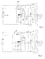
- FIG. 1 shows a first embodiment of the circuit arrangement according to the invention.
- Capacitor 22 C2 Parallel to the already known circuit arrangement, which in FIG. 1 with the same reference numerals as in FIG. 6 is a is Capacitor 22 C2 connected.
- the capacitor C2 is designed to receive energy for the drive 12 as an energy store.
- the capacitor C2 may be formed as a so-called double-layer capacitor, other embodiments are also possible.
- the energy gained can be stored with low loss.
- different approaches are possible: Among other things, it is also possible to provide a pre-charge circuit for the capacitor, so that it can be charged to a desired voltage value.
- the advantage of the precharge circuit is that the capacitor C2 is already available during the first acceleration process after switching on the industrial truck.
- the diode V3 24 is provided for the charging of the capacitor C2.
- the diode V3 24 is provided for the charging of the capacitor C2.
- C2 represents the accumulator for the braking energy, which is charged in conjunction with the diode V3 24 to a voltage level of, for example, 20% above the battery voltage.
- the diode V3 takes on the task that the capacitor C2 can be charged by the generator to a voltage level above the nominal voltage of the battery.
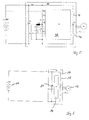
- FIG. 2 shows a possible embodiment and has a power-saving module 26, which is formed with a control unit S2 28.
- the control unit 14 and the control unit 28 are connected to each other via a CAN fieldbus 30. Via the fieldbus 30, driving and operating states of the vehicle determined by the controller S1 are communicated to the controller S2.
- the control unit 28 are at a number of input variables.
- the measured value for the battery voltage U Batt , the supply voltage U C1 and the voltage across the capacitor C2 are present. Furthermore, the current I C2 flowing through the capacitor C2 is present at the control S2.
- the capacitor C2 is connected in series with an inductance L1. Via a switch V1, the capacitor C2 and the inductance L1 is switched completely parallel to the battery 10.
- the battery 10 can be additionally switched on via the switch V3.
- the capacitor C2 In regenerative operation, for example during a braking operation, the capacitor C2 is charged by closing the switch V1 and opening the switches V2 and V3 also to voltage greater than U Batt .
- the capacitor C2 can initially only supply the intermediate circuit until a voltage has dropped to U Batt . Thereafter, switch V3 is closed and the battery takes over the supply.
- the capacitor C2 can be further discharged by switch V3 than in the in FIGS. 1 or 3 illustrated embodiments.
- the intermediate circuit voltage U C1 is additionally supported by the capacitor C2 by switching inductance L1 and switches V1 and V2 as a step-up converter.
- the capacitor C2 is charged via the generator operation of the controller and switch V1 to a voltage level which may be higher than U Batt .
- control unit 28 may provide that power is removed from the battery 10 during a vehicle standstill and a possibly insufficient charge of the capacitor C2 in order to charge the capacitor C2 for the next trip.
- FIG. 3 shows an energy-saving module 30, the energy-saving module 26 in its structural design FIG. 2 equivalent.
- a controller 32 is provided, against which U Batt , U C1 , I C2 and U C2 are present as input variables.
- the controller 32 is connected to the controller 14 via a CAN fieldbus 34.
- Unlike the in FIG. 2 illustrated variant of the energy-saving module 26 is here according to the embodiment FIG. 3 not intended to disconnect the capacitor from the battery during recharging via a switch V3, so that the charging voltage can not be regulated to a value independent of the battery voltage.
- FIG. 4 illustrated variant of an energy-saving module 36 differs from the variant FIG. 3 in that a switch V4 is provided which is connected in parallel with the capacitor C2. In the parallel branch to the capacitor C2, a further additional switch V5 is provided. Switches V4 and V5 are driven by the power-saving module 36, and allow the charging or discharging of the capacitor C2 to occur independently of a voltage change across the battery. In this way, the capacitor C2 can be switched on to keep the voltage U C1 constant at a predetermined value.
- V1, V2, V4, V5 and L1 as boost converter or as buck converter .
- FIG. 5 shows a further embodiment of the invention, in which the energy-saving module 36 from FIG. 4 is brought together with the drive control 14.
- the overall control 38 thus formed assumes the task of the drive control 14 and additionally the control S2 from the energy saving module 36.
- a connection between the two controllers via the CAN bus can be omitted.
- the battery voltage U Batt the voltage U C1 applied to the motor, and the current I C2 flowing through the capacitor C2 and the voltage U C2 applied to the capacitor C2 are again present as input variables.
- the switches V1 and V2 and V4 and V5 for loading and unloading of the capacitor C2 will be switched.
- the controller S2 further switches the switches 40 and 42 to supply the drive 12 in a known manner.
- the capacitor C1 which is provided for smoothing voltage peaks due to the switching operations, is also in FIG. 5 shown.
- the ratio of battery capacity and capacity of the capacitor used depends heavily on the vehicle use. Special advantages arise where the truck is particularly often exposed to braking or acceleration. For industrial trucks whose use allows a high level of energy recovery, the battery capacity can be significantly reduced.
- a central feature of the invention which makes it possible to integrate an additional capacitor C2 in the control of the truck, is that a step-up or step-down converter in the truck is used to support the battery voltage.
Description
Die vorliegende Erfindung betrifft ein Flurförderzeug mit einem elektrischen Antrieb, der von einer wiederaufladbaren Batterie gespeist ist. Ferner besitzt das Flurförderzeug eine Steuerung, um den elektrischen Antrieb in einen generatorischen Betrieb umzuschalten. Bei dem elektrischen Antrieb kann es sich um einen elektrischen Fahrantrieb für das Flurförderzeug handeln, es ist aber auch möglich, die Erfindung für elektrische Hubantriebe und/oder elektrische Lenkungen einzusetzen.The present invention relates to a truck with an electric drive, which is powered by a rechargeable battery. Furthermore, the truck has a control to switch the electric drive in a regenerative mode. The electric drive may be an electric traction drive for the industrial truck, but it is also possible to use the invention for electric lifting drives and / or electric steering systems.
Allgemein ist bei Flurförderzeugen bekannt, durch Umschalten des elektrischen Antriebs in einen generatorischen Betrieb elektrische Energie zu gewinnen. Gelegentlich wird diese Betriebsart für Flurförderzeuge auch als Nutzbremsen und/oder Nutzsenken bezeichnet.Generally, it is known in industrial trucks, to gain electrical energy by switching the electric drive in a regenerative operation. Occasionally, this mode of operation for industrial trucks is also referred to as regenerative brakes and / or payloads.
Bei dem herkömmlichen System wird die generatorisch gewonnene elektrische Leistung entweder in die Batterie zurückgeführt oder elektrisch direkt verbraucht.In the conventional system, the regenerative electric power is either returned to the battery or directly consumed electrically.
In der
Ein Gleichstromantrieb mit Anlasshilfe für Flurförderfahrzeuge, insbesondere Deichselfahrzeuge im Mitgehbetrieb, wird in
Der Erfindung liegt die Aufgabe zugrunde, ein Flurförderzeug mit einem elektrischen Antrieb bereitzustellen, dessen elektrische Versorgung durch eine Batterie möglichst langlebig und stabil ist.The invention has for its object to provide an industrial truck with an electric drive, the electrical supply is as durable as possible and stable by a battery.
Erfindungsgemäß wird die Aufgabe durch ein Flurförderzeug mit den Merkmalen aus Anspruch 1 gelöst. Vorteilhafte Ausgestaltungen bilden die Gegenstände der Unteransprüche.According to the invention the object is achieved by an industrial truck with the features of
Das erfindungsgemäße Flurförderzeug besitzt einen elektrischen Antrieb, der von einer wiederaufladbaren Batterie gespeist werden kann. Ferner ist das Flurförderzeug mit einer Steuerung für den elektrischen Antrieb ausgestattet, die den Antrieb in einen generatorischen Betrieb umschalten kann. Erfindungsgemäß ist ein zweiter Energiespeicher vorgesehen, der im generatorischen Betrieb des Antriebs aufladbar ist und im motorischen Betrieb den Antrieb speisen kann. Wie an sich bereits bekannt, wird bei dem erfindungsgemäßen Flurförderzeug in einen generatorischen Antrieb des elektrischen Antriebs umgeschaltet, um elektrische Energie zu gewinnen. Die elektrische Energie kann beispielsweise aus einem Bremsvorgang gewonnen werden oder aus anderen Vorgängen, wie beispielsweise dem Absenken einer Last oder der Kurvenfahrt. Bei dem erfindungsgemäßen Flurförderzeug wird die generatorisch gewonnene elektrische Energie für einen zweiten Energiespeicher eingesetzt, der im generatorischen Betrieb wieder aufgeladen wird. Im motorischen Betrieb kann der zweite Energiespeicher derart zu dem Antrieb geschaltet werden, dass der Antrieb zusätzlich durch den zweiten Energiespeicher gespeist wird.The truck according to the invention has an electric drive, which can be powered by a rechargeable battery. Furthermore, the truck is equipped with an electric drive control that can switch the drive to regenerative operation. According to the invention, a second energy store is provided, which can be charged in regenerative operation of the drive and can power the drive during motor operation. As already known, in the truck according to the invention is switched to a regenerative drive of the electric drive to recover electrical energy. The electrical energy can be obtained, for example, from a braking operation or from other processes, such as the lowering of a load or cornering. In the truck according to the invention, the regenerative electrical energy obtained is used for a second energy storage, which is recharged in regenerative operation. In motor operation, the second energy store can be switched to the drive in such a way that the drive is additionally fed by the second energy store.
Bei dem erfindungsgemäßen Flurförderzeug wird die Batterie im besonderen Maße geschont. So besteht der Vorteil, dass die Batterie im generatorischen Betrieb nicht direkt wieder aufgeladen wird, so dass die Batterie kontrollierten Lade- und Entladezyklen unterworfen werden kann. Auch bietet der weitere Energiespeicher den Vorteil, dass dieser der Versorgung des elektrischen Antriebs zugeschaltet werden kann und so die Batterie geschont wird, gerade bei einer großen Leistungsentnahme.In the truck according to the invention, the battery is spared in a special way. Thus, there is the advantage that the battery is not recharged directly in regenerative operation, so that the battery can be subjected to controlled charging and discharging cycles. The further energy storage also offers the advantage that it can be connected to the supply of the electric drive and so the battery is protected, especially with a large power extraction.
Bei einer bevorzugten Ausgestaltung des erfindungsgemäßen Flurförderzeugs ist der weitere Energiespeicher auf eine Ladespannung aufgeladen, die größer oder gleich der Batteriespannung ist. Das Aufladen des zweiten Energiespeichers auf eine besonders hohe Spannung bietet den Vorteil, dass bei Zuschalten des zweiten Energiespeichers der Antrieb mit einer ausreichend hohen Spannung versorgt werden kann, selbst wenn die Spannung aus der Batterie bereits abnimmt.In a preferred embodiment of the truck according to the invention, the further energy storage is charged to a charging voltage which is greater than or equal to the battery voltage. Charging the second energy store to a particularly high voltage offers the advantage that when the second energy store is connected, the drive can be supplied with a sufficiently high voltage, even if the voltage from the battery is already decreasing.
In einer bevorzugten Weiterbildung des erfindungsgemäßen Flurförderzeugs wird in vorbestimmten Fahr- und/oder Betriebszuständen der elektrische Antrieb von dem zweiten Energiespeicher gemeinsam mit der Batterie gespeist. In dieser Ausgestaltung erfolgt in definierten Fahr- und/oder Betriebszuständen des Flurförderzeugs ein Zuschalten des zweiten Energiespeichers zusätzlich zu der Versorgung aus der Batterie.In a preferred embodiment of the truck according to the invention, the electric drive is fed by the second energy storage together with the battery in predetermined driving and / or operating states. In this embodiment takes place in defined driving and / or operating conditions of the truck, a connection of the second energy storage in addition to the supply from the battery.
Bei den besonderen Fahr- und Betriebszuständen ist für die Zuschaltung des zweiten Energiespeichers, besonders die Beschleunigung als besonders leistungsintensiver Fahrzustand, von Interesse. Es ist daher vorgesehen, dass vorzugsweise bei einer Beschleunigung des Fahrzeugs, der zweite Energiespeicher zur zusätzlichen Spannungsversorgung eines elektrischen Fahrantriebs zugeschaltet wird. Hierbei kann für die Beschleunigung ein Mindestwert definiert sein, bei dessen Überschreiten die Zuschaltung des zweiten Energiespeichers erfolgt.In the special driving and operating conditions is for the connection of the second energy storage, especially the acceleration as a particularly power-intensive driving state of interest. It is therefore envisaged that, preferably when the vehicle accelerates, the second energy store is connected to the additional power supply of an electric traction drive. In this case, a minimum value can be defined for the acceleration, at which point the connection of the second energy store takes place.
Ebenfalls kann als eine besondere Fahrbedingung vorgesehen sein, dass bei Überschreiten einer vorbestimmten Geschwindigkeit des Flurförderzeugs der zweite Energiespeicher zur Versorgung des Fahrantriebs zugeschaltet wird. Auch bei Überschreiten einer maximalen Höchstgeschwindigkeit kann der Fahrantrieb zusätzlich durch den zweiten Energiespeicher versorgt werden.It can also be provided as a special driving condition that when a predetermined speed of the truck is exceeded, the second energy storage is switched on to supply the traction drive. Even when a maximum maximum speed is exceeded, the travel drive can be additionally supplied by the second energy storage.
Alternativ ist es auch möglich, dass der zweite Energiespeicher ausschließlich zur Spannungsversorgung des elektrischen Antriebs vorgesehen ist, wenn bestimmte Fahr- und/oder Betriebszustände für das Flurförderzeug vorliegen. In einer bevorzugten Ausgestaltung sind für das Flurförderzeug weitere Fahr- und/oder Betriebszustände definiert. Für die weiteren Fahr- und/oder Betriebszustände ist vorgesehen, dass der Energiespeicher von der Batterie auf seine Ladespannung wieder aufgeladen wird. Beispielsweise ist es möglich, als weiterer Fahr- und Betriebszustand für das Wiederaufladen des zweiten Energiespeichers, den Stillstand des Flurförderzeugs zu definieren.Alternatively, it is also possible that the second energy storage is provided exclusively for the power supply of the electric drive, if certain driving and / or operating conditions for the truck are present. In a preferred embodiment further driving and / or operating conditions are defined for the truck. For the further driving and / or operating states is provided that the energy storage is recharged by the battery to its charging voltage. For example, it is possible, as a further driving and operating state for the recharging of the second energy storage, to define the standstill of the truck.
In dem erfindungsgemäßen Flurförderzeug ist ein Neigungssensor vorgesehen, der dafür ausgelegt ist, die Neigung des Flurförderzeugs zu erkennen. Bevorzugt erfolgt ein Wiederaufladen des zweiten Energiespeichers abhängig von dem erfassten Wert für die Neigung. Hierbei wird, wenn der sensierte Wert für die Neigung eine Mindestneigung überschreitet, der zweite Energiespeicher auf einen vorbestimmten Wert wiederaufgeladen. Bei dem bestimmten Wert kann es sich um einen vorbestimmten Wert oder um einen adaptiven Wert handeln, der beispielsweise aus einer erfassten Umladebilanz der Batterie oder erfassten Betriebszuständen des Fahrzeugs ermittelt wird. In dieser Ausgestaltung wird sichergestellt, dass das an einer Rampe geneigt stehende Flurförderzeug direkt wieder anfahren kann, ohne dass die Batterie durch das Wiederaufladen des zweiten Energiespeichers geschwächt ist.In the truck according to the invention, a tilt sensor is provided, which is designed to detect the inclination of the truck. A recharging of the second energy store preferably takes place as a function of the detected value for the inclination. Here, when the sensed value for the inclination exceeds a minimum inclination, the second energy storage is recharged to a predetermined value. The determined value may be a predetermined value or an adaptive value, for example, from a detected transient balance of the battery or detected Operating conditions of the vehicle is determined. In this embodiment, it is ensured that the truck, which is inclined on a ramp, can start again directly, without the battery being weakened by the recharging of the second energy store.
Die Erfindung wird nachfolgend anhand der Figuren näher erläutert.The invention will be explained in more detail with reference to FIGS.
Es zeigt:
- Fig. 1
- eine schematische Schaltungsanordnung für einen Motor mit einer Batterie und einem parallel geschalteten Kondensator C2,
- Fig.2
- eine schematische Schaltungsanordnung für einen batteriegespeisten Motor mit einem parallel geschalteten Energiesparmodul, das einen Kondensator aufweist,
- Fig. 3
- eine schematische Schaltungsordnung eines batteriegespeisten Motors mit einem weiteren Energiesparmodul, das parallel zur Batterie geschaltet ist,
- Fig. 4
- eine schematische Schaltungsanordnung für einen batteriegespeisten Motor mit einem parallel geschalteten Energiesparmodul, das einen Kondensator als Energiespeicher aufweist,
- Fig. 5
- eine schematische Schaltungsanordnung mit einem Energiesparmodul, das einen Kondensator C2 aufweist, und
- Fig. 6
- eine schematische Schaltungsanordnung für einen batteriegespeisten Motor nach dem Stand der Technik.
- Fig. 1
- a schematic circuit arrangement for a motor with a battery and a capacitor C2 connected in parallel,
- Fig.2
- a schematic circuit arrangement for a battery-powered motor with a parallel-connected energy-saving module, which has a capacitor,
- Fig. 3
- a schematic circuit diagram of a battery-powered motor with a further energy-saving module, which is connected in parallel to the battery,
- Fig. 4
- a schematic circuit arrangement for a battery-powered motor with a parallel-connected energy-saving module having a capacitor as energy storage,
- Fig. 5
- a schematic circuit arrangement with a power-saving module having a capacitor C2, and
- Fig. 6
- a schematic circuit arrangement for a battery-powered engine according to the prior art.
Zum besseren Verständnis der Erfindung sei nachfolgend zunächst die bereits bekannte Schaltungsordnung für einen batteriegespeisten Fahrantrieb erläutert. Bei dem Antrieb kann es sich um fremderregte oder permanent erregte Gleichstromantriebe, asynchrone oder synchrone Drehstromantriebe oder Reluktanzantriebe handeln. Die Antriebe können bei einem Flurförderzeug zum Heben, Antreiben einer Hydraulik, zum Lenken oder zum Fahren vorgesehen sein.
Der parallel zur Batterie 10 geschaltete Kondensator 20 C1 ist bei der bekannten Schaltungsanordnung dafür ausgelegt, den beim Schalten des Schaltelements 14 auftretenden Wechselstromanteil aufzunehmen. Im regulären Betrieb ist die Spannung UC1, die von der Batterie an dem Antrieb 12 angelegt wird, nicht stabilisiert und folgt damit den sich durch Be- und Entladevorgänge der Batterie ergebenden Spannungsschwankungen. Erfahrungsgemäß treten Spannungsschwankungen von bis zu +/- 50% des Nominalwerts der Batterie auf, so dass die Leistungsbauelemente, wie beispielsweise das Schaltelement 18 entsprechend auszulegen sind.The parallel to the
Die Diode V3 24 ist für den Ladevorgang des Kondensators C2 vorgesehen. Durch Öffnen der Diode 24 ist es möglich, während des generatorischen Betriebes des Antriebs 12, den Kondensator C2 von der Batterie 10 zu trennen. Dies ermöglicht es, den Kondensator C2 auf eine höhere Spannung als die Spannung der Batterie zu laden. Beispielsweise kann der Kondensator C2 auf eine Ladespannung von + 20% über der Batteriespannung geladen werden. Der Kondensator C2 ist hierfür entsprechend dimensioniert.The
Beim Bremsvorgang stellt C2 den Speicher für die Bremsenergie dar, der in Verbindung mit der Diode V3 24 auf ein Spannungsniveau von beispielsweise 20% über der Batteriespannung geladen wird. Für alle nachfolgenden Beschleunigungsvorgänge des Flurförderzeugs steht dann eine größere Energiemenge im Kondensator C2 zur Stützung der Spannung UC1 zur Verfügung. Die Diode V3 übernimmt die Aufgabe, dass der Kondensator C2 durch den Generator auf ein Spannungsniveau oberhalb der Nennspannung der Batterie aufgeladen werden kann. In der angesprochenen Ausführung der Diode V3 ist es auch möglich, hier einen Transistor oder einen Schütz vorzusehen, wobei diese dann betriebssynchron über die Steuerung 14 gesteuert werden müssen.During braking, C2 represents the accumulator for the braking energy, which is charged in conjunction with the
Als zweiter Energiespeicher steht der in
An der Steuereinheit 28 liegen eine Reihe von Eingangsgrößen an. Es liegen der Messwert für die Batteriespannung UBatt, die Versorgungsspannung UC1 sowie die Spannung an dem Kondensator C2 an. Ferner liegt an der Steuerung S2 der über den Kondensator C2 fließende Strom IC2 an. Der Kondensator C2 ist mit einer Induktivität L1 in Serie geschaltet. Über einen Schalter V1 wird der Kondensator C2 und die Induktivität L1 vollständig parallel zu der Batterie 10 geschaltet. Die Batterie 10 kann über den Schalter V3 zusätzlich zugeschaltet werden.At the
Im generatorischen Betrieb, beispielsweise bei einem Bremsvorgang, wird der Kondensator C2 durch Schließen des Schalters V1 und Öffnen der Schalter V2 und V3 auch auf Spannung größer als UBatt aufgeladen. Im motorischen Betrieb der Steuereinheit 14 kann der Kondensator C2 zunächst allein den Zwischenkreis versorgen bis eine Spannung auf UBatt gesunken ist. Danach wird Schalter V3 geschlossen und die Batterie übernimmt die Versorgung. Der Kondensator C2 kann durch Schalter V3 weiter entladen werden als in den in
Ferner kann die Steuereinheit 28 vorsehen, dass bei einem Fahrzeugstillstand und einer gegebenenfalls nicht ausreichenden Ladung des Kondensators C2 Leistung aus der Batterie 10 entnommen wird, um den Kondensator C2 für die nächste Fahrt aufzuladen.Furthermore, the
Die in
Das Verhältnis von Batteriekapazität und Kapazität des eingesetzten Kondensators hängt stark vom Fahrzeugeinsatz ab. Besondere Vorteile entstehen dort, wo das Flurförderzeug besonders häufig Brems- oder Beschleunigungsvorgängen ausgesetzt ist. Für Flurförderzeuge, deren Einsatz ein hohes Maß an Rückgewinnung von Energie erlaubt, lassen sich die Batteriekapazitäten deutlich reduzieren.The ratio of battery capacity and capacity of the capacitor used depends heavily on the vehicle use. Special advantages arise where the truck is particularly often exposed to braking or acceleration. For industrial trucks whose use allows a high level of energy recovery, the battery capacity can be significantly reduced.
Dies sei an dem nachfolgenden Beispiel näher erläutert:
- Im Kommissioniereinsatz durchschnittlich einer Tonne Nutzlast werde beispielsweise eine 465 Ah-Batterie eingesetzt. Eine solche Batterie reicht erfahrungsgemäß für eine Achtstundenschicht aus. Üblicherweise durchfährt das Flurförderzeug während dieser Schicht ungefähr 480-Anfahr- und Bremsvorgänge. Dies entspricht einem Vorgang pro Minute. Bei jedem Bremsvorgang können ungefähr 250 As gerettet werden, so dass pro Schicht ungefähr 33,3 Ah gerettet werden können. In dem vorliegenden Beispiel können grob geschätzt also ungefähr 30 Ah der Batterie eingespart werden, so dass ein erfindungsgemäß ausgeführtes Flurförderzeug mit einer 435 Ah-Batterie ausgestattet werden kann.
- For example, a picking capacity of one tonne of payload would use a 465 Ah battery. Experience has shown that such a battery is sufficient for an eight-hour shift. Typically, the truck will make about 480 starts and stops during this shift. This corresponds to one operation per minute. With each braking process, about 250 Aces can be saved, so that about 33.3 Ah can be saved per shift. In the present example, roughly 30 Ah of the battery can be roughly estimated so that a truck designed according to the invention can be equipped with a 435 Ah battery.
Ein zentrales Merkmal der Erfindung, die es erlaubt, einen zusätzlichen Kondensator C2 in die Ansteuerung des Flurförderzeugs zu integrieren, besteht darin, dass ein Hoch- oder Tiefsetzsteller im Flurförderzeug zur Stützung der Batteriespannung eingesetzt wird.A central feature of the invention, which makes it possible to integrate an additional capacitor C2 in the control of the truck, is that a step-up or step-down converter in the truck is used to support the battery voltage.
Claims (10)
- An industrial truck with an electric drive (12) which can be fed by a rechargeable battery (10), and with a control system for the electric drive which can switch over the drive (12) into a generator operation, wherein
a second energy storage device (22) is provided, wherein
the second energy storage device can be charged in the generator operation of the drive (12), and feed the drive in the motor operation,
characterised in that
an inclination sensor is provided, wherein the second energy storage device is charged to a predetermined charging voltage by the battery in further predetermined travel- and operation conditions, recharging taking place depending on the detected value for the inclination. - The industrial truck according to claim 1, characterised in that the second energy storage device can be charged to a charging voltage which is greater than or equal to the battery voltage.
- An industrial truck according to claim 1 or 2, characterised in that in predetermined travel- and/or operation conditions, the electric drive is fed by the second energy storage device and by the battery.
- An industrial truck according to claim 1 or 2, characterised in that in predetermined travel- and/or operation conditions, the electric drive is fed by the second energy storage device only.
- The industrial truck according to claim 3, characterised in that upon an acceleration of the vehicle, the second energy storage device is added to the power supply of the electric travel drive.
- The industrial truck according to claim 3, characterised in that the second energy storage device is added to the power supply of the travel drive when a predetermined velocity for the industrial truck is exceeded.
- An industrial truck according to any one of claims 1 to 6, characterised in that in the standstill of the vehicle, the second energy storage device is charged depending on the value of the detected inclination.
- An industrial truck according to any one of claims 1 to 7, characterised in that when the detected value of the inclination exceeds a minimal inclination, the second energy storage device is recharged up to a predetermined value which is smaller than the battery voltage.
- An industrial truck according to any one of the preceding claims, characterised in that the second energy storage device is integrated into a control unit of the drive.
- An industrial truck according to any one of the preceding claims, characterised in that the second energy storage device is integrated into an energy saving module (26), which can exchange data with a control system (28) of the industrial truck via a field bus (30).
Applications Claiming Priority (1)
| Application Number | Priority Date | Filing Date | Title |
|---|---|---|---|
| DE102008007886A DE102008007886A1 (en) | 2008-02-04 | 2008-02-04 | Industrial truck with an electric drive |
Publications (3)
| Publication Number | Publication Date |
|---|---|
| EP2105342A2 EP2105342A2 (en) | 2009-09-30 |
| EP2105342A3 EP2105342A3 (en) | 2011-06-29 |
| EP2105342B1 true EP2105342B1 (en) | 2016-01-13 |
Family
ID=40795036
Family Applications (1)
| Application Number | Title | Priority Date | Filing Date |
|---|---|---|---|
| EP09001017.4A Expired - Fee Related EP2105342B1 (en) | 2008-02-04 | 2009-01-26 | Industrial truck with an electrical drive |
Country Status (2)
| Country | Link |
|---|---|
| EP (1) | EP2105342B1 (en) |
| DE (1) | DE102008007886A1 (en) |
Families Citing this family (5)
| Publication number | Priority date | Publication date | Assignee | Title |
|---|---|---|---|---|
| DE102012219488A1 (en) * | 2012-10-25 | 2014-04-30 | Robert Bosch Gmbh | Circuit arrangement and method for precharging a capacitive component |
| DE102014104491A1 (en) * | 2014-03-31 | 2015-10-01 | Jungheinrich Aktiengesellschaft | Industrial truck with electric drive |
| DE102014109670A1 (en) * | 2014-07-10 | 2016-01-14 | Jungheinrich Aktiengesellschaft | Truck with a battery-powered traction drive and a method for operating a battery-powered truck |
| DE102015105355A1 (en) * | 2015-04-09 | 2016-10-13 | Jungheinrich Aktiengesellschaft | Drive unit for a truck |
| DE102020203319A1 (en) | 2020-03-16 | 2021-09-16 | Volkswagen Aktiengesellschaft | High voltage system |
Family Cites Families (5)
| Publication number | Priority date | Publication date | Assignee | Title |
|---|---|---|---|---|
| DE4133303C2 (en) * | 1991-10-08 | 1994-02-17 | Jungheinrich Ag | Traction help for pedestrian vehicles in pedestrian mode |
| US5710699A (en) * | 1996-05-28 | 1998-01-20 | General Electric Company | Power electronic interface circuits for batteries and ultracapacitors in electric vehicles and battery storage systems |
| DE19628877A1 (en) * | 1996-07-17 | 1998-01-22 | Bayerische Motoren Werke Ag | Method for operating a vehicle with a first and a second drive energy source |
| CA2381035A1 (en) * | 2002-04-09 | 2003-10-09 | Powergenix Systems, Inc. | Power management for hybrid battery systems |
| DE10232639A1 (en) * | 2002-07-18 | 2004-02-12 | Hoerbiger Antriebstechnik Gmbh | Load transport vehicle, especially forklift trucks |
-
2008
- 2008-02-04 DE DE102008007886A patent/DE102008007886A1/en not_active Withdrawn
-
2009
- 2009-01-26 EP EP09001017.4A patent/EP2105342B1/en not_active Expired - Fee Related
Also Published As
| Publication number | Publication date |
|---|---|
| EP2105342A3 (en) | 2011-06-29 |
| EP2105342A2 (en) | 2009-09-30 |
| DE102008007886A1 (en) | 2009-08-06 |
Similar Documents
| Publication | Publication Date | Title |
|---|---|---|
| DE112009001196B4 (en) | Power supply device for a vehicle and method for controlling a power supply device for a vehicle | |
| EP2248239B1 (en) | Method and device for discharging a high voltage network | |
| EP2441162B1 (en) | On-board electrical system for a motor vehicle and method for operating an electrical load | |
| DE102017111884B4 (en) | Electric vehicle | |
| DE102009029849A1 (en) | System and method for starting a machine | |
| EP2105342B1 (en) | Industrial truck with an electrical drive | |
| EP2647101B1 (en) | Energy storage device for a motor vehicle | |
| DE102013008675A1 (en) | "Power source controller for a vehicle, method of controlling a power source controller and computer program product" | |
| DE102014203030A1 (en) | Method for the controlled connection of a plurality of vehicle electrical system branches of a vehicle, control unit for carrying out the method and vehicle electrical system | |
| WO2018095801A1 (en) | Operating method for a dual-voltage battery | |
| DE102011109709A1 (en) | Method for voltage supply to on-board network of e.g. motor car, involves interrupting connection between primary energy storage unit and on-board network based on a ratio of direct current voltages of energy storage units | |
| EP1526980B1 (en) | Electric drive source for a motor-drive and vehicle with said drive source | |
| DE10046631A1 (en) | Regulating generator in motor vehicle which supplies on board electric circuit with user loads and feeds at least one battery and regulator regulates output voltage to desired voltage | |
| DE102018111681A1 (en) | System for an electrically driven vehicle and vehicle with it and method for it | |
| WO2007134889A1 (en) | Method for braking electrically driven vehicles | |
| DE112008002650T5 (en) | Fuel cell output control device | |
| DE102019207601A1 (en) | POWER SUPPLY SYSTEM FOR VEHICLE | |
| WO2016020117A1 (en) | Vehicle-electrical-system assembly and method for operating a vehicle electrical system of an electrically drivable means of transportation having a fuel cell | |
| DE102009058362B4 (en) | Battery system for a motor vehicle, method for operating a battery system of a motor vehicle and motor vehicle | |
| DE102007020935A1 (en) | Method for drive control of hybrid vehicles comprises a device having combustion engine, electro machine,electrical energy source which is loaded via generated power from electro machine which is driven by combustion machine | |
| DE102012203219A1 (en) | Method for operating drive system for electric drive of vehicle, involves switching-off fuel cell system and propulsion of vehicle from energy store if loading condition of energy store lies above upper charging condition threshold | |
| DE102008061583A1 (en) | Electrical drive system for vehicle, particularly electric vehicle, has electrical drive motor and two energy storage systems which are made of multiple energy storages | |
| EP2994339B1 (en) | High voltage on-board network structure for vehicles | |
| DE102021108633A1 (en) | ENERGY SUPPLY SYSTEM | |
| DE102011076787A1 (en) | power supply |
Legal Events
| Date | Code | Title | Description |
|---|---|---|---|
| PUAI | Public reference made under article 153(3) epc to a published international application that has entered the european phase |
Free format text: ORIGINAL CODE: 0009012 |
|
| AK | Designated contracting states |
Kind code of ref document: A2 Designated state(s): AT BE BG CH CY CZ DE DK EE ES FI FR GB GR HR HU IE IS IT LI LT LU LV MC MK MT NL NO PL PT RO SE SI SK TR |
|
| AX | Request for extension of the european patent |
Extension state: AL BA RS |
|
| PUAL | Search report despatched |
Free format text: ORIGINAL CODE: 0009013 |
|
| AK | Designated contracting states |
Kind code of ref document: A3 Designated state(s): AT BE BG CH CY CZ DE DK EE ES FI FR GB GR HR HU IE IS IT LI LT LU LV MC MK MT NL NO PL PT RO SE SI SK TR |
|
| AX | Request for extension of the european patent |
Extension state: AL BA RS |
|
| RIC1 | Information provided on ipc code assigned before grant |
Ipc: B60L 15/20 20060101ALI20110526BHEP Ipc: B60L 11/18 20060101ALI20110526BHEP Ipc: B60L 11/00 20060101AFI20090827BHEP |
|
| 17P | Request for examination filed |
Effective date: 20111220 |
|
| AKX | Designation fees paid |
Designated state(s): DE FR GB IT SE |
|
| GRAP | Despatch of communication of intention to grant a patent |
Free format text: ORIGINAL CODE: EPIDOSNIGR1 |
|
| INTG | Intention to grant announced |
Effective date: 20150925 |
|
| GRAS | Grant fee paid |
Free format text: ORIGINAL CODE: EPIDOSNIGR3 |
|
| GRAA | (expected) grant |
Free format text: ORIGINAL CODE: 0009210 |
|
| AK | Designated contracting states |
Kind code of ref document: B1 Designated state(s): DE FR GB IT SE |
|
| REG | Reference to a national code |
Ref country code: GB Ref legal event code: FG4D Free format text: NOT ENGLISH |
|
| REG | Reference to a national code |
Ref country code: DE Ref legal event code: R096 Ref document number: 502009012021 Country of ref document: DE |
|
| REG | Reference to a national code |
Ref country code: FR Ref legal event code: PLFP Year of fee payment: 8 |
|
| PG25 | Lapsed in a contracting state [announced via postgrant information from national office to epo] |
Ref country code: IT Free format text: LAPSE BECAUSE OF FAILURE TO SUBMIT A TRANSLATION OF THE DESCRIPTION OR TO PAY THE FEE WITHIN THE PRESCRIBED TIME-LIMIT Effective date: 20160113 |
|
| PG25 | Lapsed in a contracting state [announced via postgrant information from national office to epo] |
Ref country code: SE Free format text: LAPSE BECAUSE OF FAILURE TO SUBMIT A TRANSLATION OF THE DESCRIPTION OR TO PAY THE FEE WITHIN THE PRESCRIBED TIME-LIMIT Effective date: 20160113 |
|
| REG | Reference to a national code |
Ref country code: DE Ref legal event code: R097 Ref document number: 502009012021 Country of ref document: DE |
|
| PLBE | No opposition filed within time limit |
Free format text: ORIGINAL CODE: 0009261 |
|
| STAA | Information on the status of an ep patent application or granted ep patent |
Free format text: STATUS: NO OPPOSITION FILED WITHIN TIME LIMIT |
|
| 26N | No opposition filed |
Effective date: 20161014 |
|
| REG | Reference to a national code |
Ref country code: FR Ref legal event code: PLFP Year of fee payment: 9 |
|
| REG | Reference to a national code |
Ref country code: FR Ref legal event code: PLFP Year of fee payment: 10 |
|
| PGFP | Annual fee paid to national office [announced via postgrant information from national office to epo] |
Ref country code: FR Payment date: 20210127 Year of fee payment: 13 |
|
| PGFP | Annual fee paid to national office [announced via postgrant information from national office to epo] |
Ref country code: GB Payment date: 20210128 Year of fee payment: 13 |
|
| PGFP | Annual fee paid to national office [announced via postgrant information from national office to epo] |
Ref country code: DE Payment date: 20210329 Year of fee payment: 13 |
|
| REG | Reference to a national code |
Ref country code: DE Ref legal event code: R119 Ref document number: 502009012021 Country of ref document: DE |
|
| GBPC | Gb: european patent ceased through non-payment of renewal fee |
Effective date: 20220126 |
|
| PG25 | Lapsed in a contracting state [announced via postgrant information from national office to epo] |
Ref country code: GB Free format text: LAPSE BECAUSE OF NON-PAYMENT OF DUE FEES Effective date: 20220126 Ref country code: DE Free format text: LAPSE BECAUSE OF NON-PAYMENT OF DUE FEES Effective date: 20220802 |
|
| PG25 | Lapsed in a contracting state [announced via postgrant information from national office to epo] |
Ref country code: FR Free format text: LAPSE BECAUSE OF NON-PAYMENT OF DUE FEES Effective date: 20220131 |