EP2647101B1 - Energy storage device for a motor vehicle - Google Patents
Energy storage device for a motor vehicle Download PDFInfo
- Publication number
- EP2647101B1 EP2647101B1 EP11790946.5A EP11790946A EP2647101B1 EP 2647101 B1 EP2647101 B1 EP 2647101B1 EP 11790946 A EP11790946 A EP 11790946A EP 2647101 B1 EP2647101 B1 EP 2647101B1
- Authority
- EP
- European Patent Office
- Prior art keywords
- electrical energy
- energy storage
- voltage
- energy store
- charge
- Prior art date
- Legal status (The legal status is an assumption and is not a legal conclusion. Google has not performed a legal analysis and makes no representation as to the accuracy of the status listed.)
- Active
Links
- 238000004146 energy storage Methods 0.000 title claims description 88
- 239000002253 acid Substances 0.000 claims description 24
- HBBGRARXTFLTSG-UHFFFAOYSA-N Lithium ion Chemical compound [Li+] HBBGRARXTFLTSG-UHFFFAOYSA-N 0.000 claims description 14
- 229910001416 lithium ion Inorganic materials 0.000 claims description 14
- 238000000034 method Methods 0.000 claims description 3
- 230000008569 process Effects 0.000 claims description 3
- 230000007935 neutral effect Effects 0.000 claims 1
- 230000008901 benefit Effects 0.000 description 6
- 230000003993 interaction Effects 0.000 description 5
- 230000008878 coupling Effects 0.000 description 3
- 238000010168 coupling process Methods 0.000 description 3
- 238000005859 coupling reaction Methods 0.000 description 3
- 238000011161 development Methods 0.000 description 3
- 230000018109 developmental process Effects 0.000 description 3
- 230000000694 effects Effects 0.000 description 3
- 239000003990 capacitor Substances 0.000 description 2
- 238000007599 discharging Methods 0.000 description 2
- 238000011084 recovery Methods 0.000 description 2
- 238000012546 transfer Methods 0.000 description 2
- 238000001816 cooling Methods 0.000 description 1
- 230000001419 dependent effect Effects 0.000 description 1
- 238000001514 detection method Methods 0.000 description 1
- 230000003292 diminished effect Effects 0.000 description 1
- 230000002349 favourable effect Effects 0.000 description 1
- 230000010354 integration Effects 0.000 description 1
- 238000012423 maintenance Methods 0.000 description 1
- 238000005259 measurement Methods 0.000 description 1
- 238000012544 monitoring process Methods 0.000 description 1
- 230000001172 regenerating effect Effects 0.000 description 1
- 238000005096 rolling process Methods 0.000 description 1
- 230000000087 stabilizing effect Effects 0.000 description 1
- 239000000126 substance Substances 0.000 description 1
Images

Classifications
-
- B—PERFORMING OPERATIONS; TRANSPORTING
- B60—VEHICLES IN GENERAL
- B60R—VEHICLES, VEHICLE FITTINGS, OR VEHICLE PARTS, NOT OTHERWISE PROVIDED FOR
- B60R16/00—Electric or fluid circuits specially adapted for vehicles and not otherwise provided for; Arrangement of elements of electric or fluid circuits specially adapted for vehicles and not otherwise provided for
- B60R16/02—Electric or fluid circuits specially adapted for vehicles and not otherwise provided for; Arrangement of elements of electric or fluid circuits specially adapted for vehicles and not otherwise provided for electric constitutive elements
- B60R16/03—Electric or fluid circuits specially adapted for vehicles and not otherwise provided for; Arrangement of elements of electric or fluid circuits specially adapted for vehicles and not otherwise provided for electric constitutive elements for supply of electrical power to vehicle subsystems or for
- B60R16/033—Electric or fluid circuits specially adapted for vehicles and not otherwise provided for; Arrangement of elements of electric or fluid circuits specially adapted for vehicles and not otherwise provided for electric constitutive elements for supply of electrical power to vehicle subsystems or for characterised by the use of electrical cells or batteries
-
- H—ELECTRICITY
- H02—GENERATION; CONVERSION OR DISTRIBUTION OF ELECTRIC POWER
- H02J—CIRCUIT ARRANGEMENTS OR SYSTEMS FOR SUPPLYING OR DISTRIBUTING ELECTRIC POWER; SYSTEMS FOR STORING ELECTRIC ENERGY
- H02J7/00—Circuit arrangements for charging or depolarising batteries or for supplying loads from batteries
- H02J7/14—Circuit arrangements for charging or depolarising batteries or for supplying loads from batteries for charging batteries from dynamo-electric generators driven at varying speed, e.g. on vehicle
- H02J7/1423—Circuit arrangements for charging or depolarising batteries or for supplying loads from batteries for charging batteries from dynamo-electric generators driven at varying speed, e.g. on vehicle with multiple batteries
-
- B—PERFORMING OPERATIONS; TRANSPORTING
- B60—VEHICLES IN GENERAL
- B60L—PROPULSION OF ELECTRICALLY-PROPELLED VEHICLES; SUPPLYING ELECTRIC POWER FOR AUXILIARY EQUIPMENT OF ELECTRICALLY-PROPELLED VEHICLES; ELECTRODYNAMIC BRAKE SYSTEMS FOR VEHICLES IN GENERAL; MAGNETIC SUSPENSION OR LEVITATION FOR VEHICLES; MONITORING OPERATING VARIABLES OF ELECTRICALLY-PROPELLED VEHICLES; ELECTRIC SAFETY DEVICES FOR ELECTRICALLY-PROPELLED VEHICLES
- B60L58/00—Methods or circuit arrangements for monitoring or controlling batteries or fuel cells, specially adapted for electric vehicles
- B60L58/10—Methods or circuit arrangements for monitoring or controlling batteries or fuel cells, specially adapted for electric vehicles for monitoring or controlling batteries
- B60L58/18—Methods or circuit arrangements for monitoring or controlling batteries or fuel cells, specially adapted for electric vehicles for monitoring or controlling batteries of two or more battery modules
- B60L58/20—Methods or circuit arrangements for monitoring or controlling batteries or fuel cells, specially adapted for electric vehicles for monitoring or controlling batteries of two or more battery modules having different nominal voltages
-
- H—ELECTRICITY
- H01—ELECTRIC ELEMENTS
- H01M—PROCESSES OR MEANS, e.g. BATTERIES, FOR THE DIRECT CONVERSION OF CHEMICAL ENERGY INTO ELECTRICAL ENERGY
- H01M16/00—Structural combinations of different types of electrochemical generators
-
- H—ELECTRICITY
- H02—GENERATION; CONVERSION OR DISTRIBUTION OF ELECTRIC POWER
- H02J—CIRCUIT ARRANGEMENTS OR SYSTEMS FOR SUPPLYING OR DISTRIBUTING ELECTRIC POWER; SYSTEMS FOR STORING ELECTRIC ENERGY
- H02J7/00—Circuit arrangements for charging or depolarising batteries or for supplying loads from batteries
- H02J7/34—Parallel operation in networks using both storage and other dc sources, e.g. providing buffering
- H02J7/345—Parallel operation in networks using both storage and other dc sources, e.g. providing buffering using capacitors as storage or buffering devices
-
- Y—GENERAL TAGGING OF NEW TECHNOLOGICAL DEVELOPMENTS; GENERAL TAGGING OF CROSS-SECTIONAL TECHNOLOGIES SPANNING OVER SEVERAL SECTIONS OF THE IPC; TECHNICAL SUBJECTS COVERED BY FORMER USPC CROSS-REFERENCE ART COLLECTIONS [XRACs] AND DIGESTS
- Y02—TECHNOLOGIES OR APPLICATIONS FOR MITIGATION OR ADAPTATION AGAINST CLIMATE CHANGE
- Y02T—CLIMATE CHANGE MITIGATION TECHNOLOGIES RELATED TO TRANSPORTATION
- Y02T10/00—Road transport of goods or passengers
- Y02T10/60—Other road transportation technologies with climate change mitigation effect
- Y02T10/70—Energy storage systems for electromobility, e.g. batteries
Definitions
- the invention relates to an energy storage device for a motor vehicle having a first electrical energy storage, which is characterized by a first voltage characteristic, which determines the rest voltage of the first electrical energy storage in dependence on its relative state of charge, as well as by a first resistance characteristic corresponding to that for a charging of the first electrical energy storage relevant internal resistance of the first electrical energy storage as a function of its relative state of charge sets, and with the first electrical energy storage parallel-connected second electrical energy storage, which is characterized by a second voltage characteristic which the rest voltage of the second electrical energy storage in dependence on its relative state of charge determines, as well as by a second resistance characteristic which the relevant for a charging process of the second electrical energy storage mecanicw iderstand the second electrical energy storage in dependence of its relative state of charge determines.
- the lead-acid battery can be replaced, for example, by a more suitable energy storage or supplemented the electrical system to another energy storage and expanded to a two-energy storage electrical system.
- Such energy storage devices in a vehicle electrical system are explained in the prior art as a two-energy storage electrical system.
- US 6,844,634 B2 a parallel circuit of a lead-acid battery with a lithium-ion battery as a basis for a scheme for generating electrical power in the vehicle described.
- the interaction of two sensors for the accumulators with a control unit in the foreground shows WO 2005/027345 A1 an energy storage device in a vehicle electrical system that can provide electrical power to a load at different power rates.
- the energy storage device comprises two energy stores in the form of an energy-optimized battery ("energy battery”) and a power-optimized battery (“power battery”), wherein the power-optimized battery can be recharged by the energy-optimized battery.
- the energy storage device is characterized by a partial overlap of the voltage value range which is covered by the voltage characteristic of the first electrical energy store, referred to herein as the first voltage characteristic, with the voltage value range which is covered by the voltage characteristic of the second electrical energy store, referred to here as the second voltage characteristic becomes.
- a partial overlapping of the two voltage value ranges is to be understood as meaning that in addition to a non-zero intersection of the two voltage value ranges, a subset of the non-zero subset Voltage range exists that does not represent a subset of the other voltage range.
- the internal resistance characteristic of the first electrical energy store in charging referred to as the first resistance characteristic
- the internal resistance characteristic of the second electrical energy store when charging referred to as the second resistance characteristic, exactly one intersection, wherein upon application of an external charging voltage to the energy storage device, the first electrical energy storage and the second electrical energy store are connected in parallel to effect charging of the energy store with the lower charging resistance as a function of the relative charge states.
- An advantage of the invention is that an interaction of the two electrical energy storage arises with respect to their voltage levels and their relative states of charge.
- a charging current or a discharge current of the energy storage device is determined at any time by the addition of the respective charging or discharging currents of the two electrical energy storage devices.
- the parallel connection of the two electrical energy stores constitutes a node
- the observance of a sign convention for the two directions of the current flow is assumed, ie for the charging current as a flow direction (a sign) and the discharge current as the other flow direction (the other sign).
- the technical effort for the operation of the energy storage device in the motor vehicle includes in the context of the present document, for example, battery sensors for monitoring voltages and currents of the two electrical energy storage or regulation of the charging and discharging the two electrical energy storage.
- battery sensors for monitoring voltages and currents of the two electrical energy storage or regulation of the charging and discharging the two electrical energy storage.
- Such a control is often referred to in automotive engineering as an operating strategy of electrical energy storage and implemented in the form of a software module on a control unit.
- the life of the energy storage device can be optimized by the interaction of the two electrical energy storage.
- the first resistance characteristic runs above the second resistance characteristic curve at relative states of charge which are above the value of the relative state of charge at the point of intersection.
- the value of the relative state of charge at the intersection of the two resistance characteristics is referred to as the critical state of charge in the further course of the document.
- the resistance values of the first resistance characteristic for large state of charge values are greater than the resistance values of the second resistance characteristic.
- the particular advantage of this embodiment is that, in the case of the concern of an external charging voltage to the energy storage device, which may be generated for example by a vehicle electrical system generator, the second electrical energy storage device has a lower charging resistance than the first electrical energy storage. This applies at least when the relative state of charge of the first electrical energy store is above the critical state of charge and the relative state of charge of the second electrical energy store is below the critical state of charge.
- a short-time charging pulse such as frequently occurring in modern functions for regenerative braking, thus leads to a preferred charge of the second electrical energy storage.
- the energy storage device (or the energy stores contained therein) is designed such that the voltage value range covered by the second voltage characteristic includes higher voltage values than the voltage value range covered by the first voltage characteristic.
- the relative charging state of the first electrical energy store is greater than the relative charging state of the second electrical energy store in the same voltage situation of the two electrical energy stores due to the parallel connection.
- the features of the two voltage characteristics have the advantage that preferably the first electrical energy storage is charged by the second electrical energy storage when no external charging voltage applied to the energy storage device. In the further course of the document, this effect is referred to as internal transhipment. In addition, only a charging current from the second to the first electrical energy storage flow (ie, an internal transfer occur), if neither the first electrical energy storage fully charged nor the second electrical energy storage is completely discharged. In other words, this means that due to the parallel connection of the two electrical energy storage same voltage level of the two electrical energy storage is in the range of partial overlap of the two voltage characteristics.
- the energy storage device can be designed so that the first electrical energy storage as a lead-acid storage battery is executed and the second electrical energy storage is designed as a lithium-ion battery or as a super-capacitor.
- the lead-acid storage battery is preferably operated at higher relative charge states than the lithium-ion battery or the super-capacitor.
- the life of a lead-acid battery increases in a first approximation with the averaged over a longer period of use relative state of charge. If such an operating strategy of the energy storage device is chosen to operate the lead-acid storage battery at relative state of charge values near full charge, optimized availability of the energy storage device is ensured. Warranty costs for the motor vehicle manufacturer and maintenance costs for the motor vehicle owner are reduced.
- the parallel connection of the two electrical energy storage is carried out voltage-neutral.
- a voltage-neutral embodiment of the parallel connection of the two electrical energy storage an embodiment is described in the present document, in which at no time of operation one or a significant electrical voltage drops at connection or coupling elements.
- a fixed wiring, a simple switch and / or a relay can be regarded as voltage-neutral interconnection, for example.
- voltage-converting components such as a DC-DC converter or the two electrical energy storage devices are partially decoupled switch controls excluded that have divergent voltage levels of the two electrical energy storage during their operation result.
- the simplicity of the operating strategy is also expressed in the further cost advantage that, during operation of the energy storage device, the detection of the energy storage voltage is sufficient for determining the relative charge state for one of the two electrical energy stores. If, for example, the open circuit voltage between the poles of the lead-acid accumulator is detected, the two voltage characteristics of the two electrical circuits are due to the known position of the two voltage characteristics Energy storage to each other, the relative charge state of the lithium-ion battery mitbestimmt with sufficient accuracy.
- Two electrochemical energy stores can be coupled directly without a voltage-converting coupling element, wherein the two energy stores have a different, but coordinated behavior of their voltage characteristics as a function of their state of charge.
- This characteristic of the two energy storage devices ensures that a complex connection through a DC-DC converter or switch control is not necessary.
- the coupling can be implemented by a resistive, wired connection of a lead-acid battery with rated voltage 12 volts and a lithium-ion battery with rated voltage 14 volts.
- a lead acid accumulator such as good cold start capability and favorable cost-benefit ratio are ideally complemented.
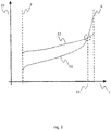
- Fig. 1 shows the course of a voltage characteristic of a first electrical energy store (5), which can be designed as a secondary lead-acid battery with a nominal voltage of 12 volts, plotted in the direction of the high-value axis (2) in dependence on their relative state of charge (1).
- a first electrical energy store (5) which can be designed as a secondary lead-acid battery with a nominal voltage of 12 volts
- Fig. 1 shows the course of a voltage characteristic of a first electrical energy store (5), which can be designed as a secondary lead-acid battery with a nominal voltage of 12 volts, plotted in the direction of the high-value axis (2) in dependence on their relative state of charge (1).
- the range of the relative state of charge between discharge (3) of the energy storage and full charge (4) of the energy storage is shown, the range of possible deep discharge is not shown.
- Fig. 1 the course of an analog voltage characteristic curve of a second electrical energy store (6), which is plotted in the direction of the high-value axis and
- the two voltage characteristics show the quiescent voltage of the electrical energy storage in the state of equilibrium, which means that the voltage between the battery poles is shown without load or external charging voltage and after a sufficiently long for the setting of a thermal and chemical equilibrium period.
- the voltage range (7) covered by the first voltage characteristic (5) and the voltage range (8) covered by the second voltage characteristic (6) have an intersection (9), that is, not the entire voltage range covered by the first voltage characteristic is present larger voltage values than the voltage range covered by the second voltage characteristic.
- Fig. 2 shows the in the direction of the high-value axis (10) plotted course of the internal resistance of the first electrical energy storage device (11) during a charging operation. This course is plotted against the relative state of charge (1) in the region between discharge (3) and full charge (4). In an analogous manner, the course of the internal resistance of the second electrical energy store (12) is shown.
- the intersection of the two resistance characteristics is associated with a value of the relative state of charge (13), which is referred to as a critical state of charge.
- the critical state of charge can be used as a control and regulation parameter.
- the state of charge of the lead-acid battery is to be detected, for example by a voltage measurement with a battery sensor.
- a charging voltage of the energy storage device for example, 13.3 volts is sufficient to fully charge the lead-acid battery, wherein the lithium-ion battery after full charge of the lead-acid battery in a partially discharged state, and preferably below the critical Charge state is located. If the lead-acid battery is above the critical state of charge at relative states of charge, this results in a short-time charging pulse, which is applied to the energy storage device, for example, to recover braking energy in a rolling phase of the motor vehicle as electrochemically bound energy, preferably for charging the lithium-ion battery. As a result, the higher charging efficiency of the lithium-ion battery is used and the lead-acid battery is cyclized less in favor of their durability.
- the internal recharge reduces the residence time of the lead-acid battery at low charge states and therefore increases the life of the lead-acid battery.
- the high cold-start capability of the lead-acid battery also comes into its own due to the fact that it is not or hardly diminished in the state of high state of charge.
- the energy storage device helps to increase the likelihood of a successful and as fast as possible cold start of the engine of the motor vehicle. In this case, however, no such long service life before a cold start of the engine or micro-shorts in the electrical energy storage are considered, leading to a total discharge of the two electrical energy storage.
- the energy storage device stabilizes the vehicle electrical system without the use of expensive DC controllers, since both electrical energy storage are discharged in parallel and thus a resulting voltage dip in the energy storage device and the electrical system compared to the use of only one the two electrical energy storage is reduced.
Description
Die Erfindung betrifft eine Energiespeichervorrichtung für ein Kraftfahrzeug mit einem ersten elektrischen Energiespeicher, der charakterisiert ist durch eine erste Spannungskennlinie, welche die Ruhespannung des ersten elektrischen Energiespeichers in Abhängigkeit von seinem relativen Ladezustand festlegt, sowie durch eine erste Widerstandskennlinie, welche den für einen Ladevorgang des ersten elektrischen Energiespeichers relevanten Innenwiderstand des ersten elektrischen Energiespeichers in Abhängigkeit von seinem relativen Ladezustand festlegt, und mit einem dem ersten elektrischen Energiespeicher parallel geschalteten zweiten elektrischen Energiespeicher, der charakterisiert ist durch eine zweite Spannungskennlinie, welche die Ruhespannung des zweiten elektrischen Energiespeichers in Abhängigkeit von seinem relativen Ladezustand festlegt, sowie durch eine zweite Widerstandskennlinie, welche den für einen Ladevorgang des zweiten elektrischen Energiespeichers relevanten Innenwiderstand des zweiten elektrischen Energiespeichers in Abhängigkeit von seinem relativen Ladezustand festlegt.The invention relates to an energy storage device for a motor vehicle having a first electrical energy storage, which is characterized by a first voltage characteristic, which determines the rest voltage of the first electrical energy storage in dependence on its relative state of charge, as well as by a first resistance characteristic corresponding to that for a charging of the first electrical energy storage relevant internal resistance of the first electrical energy storage as a function of its relative state of charge sets, and with the first electrical energy storage parallel-connected second electrical energy storage, which is characterized by a second voltage characteristic which the rest voltage of the second electrical energy storage in dependence on its relative state of charge determines, as well as by a second resistance characteristic which the relevant for a charging process of the second electrical energy storage Innenw iderstand the second electrical energy storage in dependence of its relative state of charge determines.
Durch die zunehmende Zahl elektrischer Verbraucher für Komfort- und Sicherheitsfunktionen und durch die aktive Einbindung des herkömmlichen Blei-Säure-Akkumulators als elektrischem Energiespeicher in hybride Fahrzeugfunktionen wird die zukünftige Ausführung des konventionellen 14-Volt-Bordnetzes in modernen Kraftfahrzeugen, insbesondere in Personenkraftwagen, künftig starken Veränderungen unterliegen. Beispielsweise werden vermehrt Funktionalitäten wie ein automatisches Abstellen und Starten des Motors während des Fahrzeugbetriebs sowie eine effiziente Bremsenergierückgewinnung im Schubbetrieb des Fahrzeugs umgesetzt. Die daraus resultierenden Herausforderungen für den Energiespeicher werden durch häufigere Entladephasen im Hochstrombereich verschärft, die auf in modernen Fahrzeugen elektrifizierte Zusatzaggregate zurückzuführen sind. Zum Beispiel können hier elektrische oder elektromechanische Verbraucher wie Elektromotoren für aktive Lenkungen oder Kühlkreislaufpumpen angeführt werden. Um die Verfügbarkeit von Verbraucherfunktionen zu erhöhen und die Lebensdauer des Energiespeichers zu verlängern, kann der Blei-Säure-Akkumulator beispielsweise durch einen geeigneteren Energiespeicher ersetzt werden oder das Bordnetz um einen weiteren Energiespeicher ergänzt und zu einem Zwei-Energiespeicher-Bordnetz erweitert werden.Due to the increasing number of electrical consumers for comfort and safety functions and the active integration of the conventional lead-acid battery as an electric energy storage in hybrid vehicle functions, the future implementation of conventional 14-volt electrical system in modern motor vehicles, especially in passenger cars, strong future Changes are subject. For example, functionalities such as automatic stopping and starting of the engine during vehicle operation as well as efficient brake energy recovery in overrun operation of the vehicle are increasingly being implemented. The resulting challenges for the energy storage are exacerbated by more frequent discharge phases in the high current range, which are due to electrified in modern vehicles auxiliary units. For example, electrical or electromechanical consumers such as electric motors for active steering or cooling circulation pumps can be cited here. To increase the availability of consumer functions and extend the life of the energy storage, the lead-acid battery can be replaced, for example, by a more suitable energy storage or supplemented the electrical system to another energy storage and expanded to a two-energy storage electrical system.
Derartige Energiespeichervorrichtungen in einem Fahrzeugbordnetz sind im Stand der Technik als Zwei-Energiespeicher-Bordnetz erläutert. Beispielsweise wird im Dokument
Es ist eine Aufgabe der vorliegenden Erfindung, eine verbesserte Energiespeichervorrichtung für ein Kraftfahrzeug mit zwei elektrischen Energiespeichern anzugeben.It is an object of the present invention to provide an improved energy storage device for a motor vehicle with two electrical energy storage.
Gelöst wird diese Aufgabe durch eine Energiespeichervorrichtung gemäß Anspruch 1. Vorteilhafte Ausführungsformen und Weiterbildungen der Erfindung ergeben sich aus den abhängigen Ansprüchen.This object is achieved by an energy storage device according to
Erfindungsgemäß ist die Energiespeichervorrichtung gekennzeichnet durch eine teilweise Überlappung des Spannungswertebereichs, der von der Spannungskennlinie des ersten elektrischen Energiespeichers, hier als erste Spannungskennlinie bezeichnet, abgedeckt wird, mit dem Spannungswertebereich, der von der Spannungskennlinie des zweiten elektrischen Energiespeichers, hier als zweite Spannungskennlinie bezeichnet, abgedeckt wird. Unter einer teilweisen Überlappung der beiden Spannungswertebereiche ist im Rahmen des vorliegenden Dokuments zu verstehen, dass neben einer von Null verschiedenen Schnittmenge der beiden Spannungswertebereiche jeweils eine von Null verschiedene Teilmenge des Spannungswertebereichs existiert, die keine Teilmenge des anderen Spannungswertebereichs darstellt. Zudem weisen die Innenwiderstandskennlinie des ersten elektrischen Energiespeichers beim Laden, als erste Widerstandskennlinie bezeichnet, und die Innenwiderstandskennlinie des zweiten elektrischen Energiespeichers beim Laden, als zweite Widerstandskennlinie bezeichnet, genau einen Schnittpunkt auf, wobei bei Anliegen einer äußeren Ladespannung an der Energiespeichervorrichtung der erste elektrische Energiespeicher und der zweite elektrische Energiespeicher parallel geschaltet sind, um in Abhängigkeit von den relativen Ladezuständen das Laden des Energiespeichers mit dem geringeren Ladewiderstand zu bewirken.According to the invention, the energy storage device is characterized by a partial overlap of the voltage value range which is covered by the voltage characteristic of the first electrical energy store, referred to herein as the first voltage characteristic, with the voltage value range which is covered by the voltage characteristic of the second electrical energy store, referred to here as the second voltage characteristic becomes. In the context of the present document, a partial overlapping of the two voltage value ranges is to be understood as meaning that in addition to a non-zero intersection of the two voltage value ranges, a subset of the non-zero subset Voltage range exists that does not represent a subset of the other voltage range. In addition, the internal resistance characteristic of the first electrical energy store in charging, referred to as the first resistance characteristic, and the internal resistance characteristic of the second electrical energy store when charging, referred to as the second resistance characteristic, exactly one intersection, wherein upon application of an external charging voltage to the energy storage device, the first electrical energy storage and the second electrical energy store are connected in parallel to effect charging of the energy store with the lower charging resistance as a function of the relative charge states.
Ein Vorteil der Erfindung liegt darin, dass eine Wechselwirkung der beiden elektrischen Energiespeicher hinsichtlich ihrer Spannungslagen und ihrer relativen Ladezustände entsteht. Nach den Kirchhoffschen Regeln ist zu jedem Zeitpunkt ein Ladestrom oder ein Entladestrom der Energiespeichervorrichtung durch die Addition der jeweiligen Lade- oder Entladeströme der beiden elektrischen Energiespeicher festgelegt. Im Sinne der Anwendbarkeit der Kirchhoffschen Regeln stellt die Parallelschaltung der beiden elektrischen Energiespeicher einen Knotenpunkt dar. Dabei ist die Einhaltung einer Vorzeichenkonvention für die beiden Richtungen des Stromflusses vorausgesetzt, d.h. für den Ladestrom als eine Flussrichtung (ein Vorzeichen) und den Entladestrom als die andere Flussrichtung (das andere Vorzeichen). Durch diese Wechselwirkung kann der technische Aufwand für den Betrieb der Energiespeichervorrichtung im Kraftfahrzeug minimiert werden. Der technische Aufwand für den Betrieb der Energiespeichervorrichtung im Kraftfahrzeug umfasst im Kontext des vorliegenden Dokuments beispielsweise Batteriesensoren für eine Überwachung von Spannungen und Strömen der beiden elektrischen Energiespeicher oder eine Regelung der Lade- und Entladeströme der beiden elektrischen Energiespeicher. Eine solche Regelung wird in der Kraftfahrzeugtechnik häufig als Betriebsstrategie von elektrischen Energiespeichern bezeichnet und in Form eines Softwaremoduls auf einem Steuergerät implementiert.An advantage of the invention is that an interaction of the two electrical energy storage arises with respect to their voltage levels and their relative states of charge. According to Kirchhoff's rules, a charging current or a discharge current of the energy storage device is determined at any time by the addition of the respective charging or discharging currents of the two electrical energy storage devices. In the sense of the applicability of Kirchhoff's rules, the parallel connection of the two electrical energy stores constitutes a node In this case, the observance of a sign convention for the two directions of the current flow is assumed, ie for the charging current as a flow direction (a sign) and the discharge current as the other flow direction (the other sign). Through this interaction, the technical complexity for the operation of the energy storage device in the motor vehicle can be minimized. The technical effort for the operation of the energy storage device in the motor vehicle includes in the context of the present document, for example, battery sensors for monitoring voltages and currents of the two electrical energy storage or regulation of the charging and discharging the two electrical energy storage. Such a control is often referred to in automotive engineering as an operating strategy of electrical energy storage and implemented in the form of a software module on a control unit.
Die besondere Wechselwirkung der beiden elektrischen Energiespeicher ermöglicht die Umsetzung einer einfachen Betriebsstrategie mit hoher Funktionalität wie im Ausführungsbeispiel dieser Schrift erläutert wird.The special interaction of the two electrical energy storage allows the implementation of a simple operating strategy with high functionality as explained in the embodiment of this document.
Besonders vorteilhaft ist auch, dass durch die Wechselwirkung der beiden elektrischen Energiespeicher die Lebensdauer der Energiespeichereinrichtung optimiert werden kann.It is also particularly advantageous that the life of the energy storage device can be optimized by the interaction of the two electrical energy storage.
Gemäß einer bevorzugten Ausführungsform der Erfindung verläuft die erste Widerstandskennlinie bei relativen Ladezuständen, die sich über dem Wert des relativen Ladezustands beim Schnittpunkt befinden, oberhalb der zweiten Widerstandskennlinie. Der Wert des relativen Ladezustands beim Schnittpunkt der beiden Widerstandskennlinien wird im weiteren Verlauf des Dokuments als kritischer Ladezustand bezeichnet. Mit anderen Worten ausgedrückt sind die Widerstandswerte der ersten Widerstandskennlinie für große Ladezustandswerte (größer als der kritische Ladezustand am Schnittpunkt der beiden Widerstandskennlinien) größer als die Widerstandswerte der zweiten Widerstandskennlinie.According to a preferred embodiment of the invention, the first resistance characteristic runs above the second resistance characteristic curve at relative states of charge which are above the value of the relative state of charge at the point of intersection. The value of the relative state of charge at the intersection of the two resistance characteristics is referred to as the critical state of charge in the further course of the document. In other words, the resistance values of the first resistance characteristic for large state of charge values (greater than the critical state of charge at the intersection of the two resistance characteristics) are greater than the resistance values of the second resistance characteristic.
Der besondere Vorteil dieser Ausführungsform liegt darin, dass im Falle des Anliegens einer äußeren Ladespannung an der Energiespeichervorrichtung, die beispielsweise von einem Bordnetzgenerator erzeugt sein kann, der zweite elektrische Energiespeicher einen geringeren Ladewiderstand als der erste elektrische Energiespeicher aufweist. Dies gilt zumindest dann, wenn der relative Ladezustand des ersten elektrischen Energiespeichers über dem kritischen Ladezustand liegt und der relative Ladezustand des zweiten elektrischen Energiespeichers unter dem kritischen Ladezustand liegt. Ein kurzzeitiger Ladepuls, wie beispielsweise bei modernen Funktionen zur Bremsenergierückgewinnung häufig auftretend, führt somit zu einer bevorzugten Ladung des zweiten elektrischen Energiespeichers.The particular advantage of this embodiment is that, in the case of the concern of an external charging voltage to the energy storage device, which may be generated for example by a vehicle electrical system generator, the second electrical energy storage device has a lower charging resistance than the first electrical energy storage. This applies at least when the relative state of charge of the first electrical energy store is above the critical state of charge and the relative state of charge of the second electrical energy store is below the critical state of charge. A short-time charging pulse, such as frequently occurring in modern functions for regenerative braking, thus leads to a preferred charge of the second electrical energy storage.
Nach einer weiteren Variante der vorliegenden Erfindung wird die Energiespeichervorrichtung (bzw. werden die darin enthaltenen Energiespeicher) derart ausgelegt, dass der von der zweiten Spannungskennlinie abgedeckte Spannungswertebereich höhere Spannungswerte beinhaltet als der von der ersten Spannungskennlinie abgedeckte Spannungswertebereich.According to a further variant of the present invention, the energy storage device (or the energy stores contained therein) is designed such that the voltage value range covered by the second voltage characteristic includes higher voltage values than the voltage value range covered by the first voltage characteristic.
Gemäß der dem Fachmann bekannten Gleichung nach Nernst wird ein stetiger, monoton steigender Verlauf der beiden Spannungskennlinien in Richtung größerer Spannungswerte und in Richtung größerer relativer Ladezustandswerte vorausgesetzt. Etwaige Abweichungen durch Überspannungspotentiale wirken im Kontext des vorliegenden Dokuments nicht beschränkend. In ihrem Verlauf schneiden sich die beiden Spannungskennlinien nicht.According to the Nernst equation known to those skilled in the art, a steady, monotonically increasing profile of the two voltage characteristics in the direction of larger voltage values and in the direction of larger relative state of charge values is assumed. Any deviations due to overvoltage potentials are not restrictive in the context of the present document. In their course, the two voltage characteristics do not intersect.
Die Merkmale der beiden Spannungskennlinien haben zur Folge, dass bei der durch die Parallelschaltung bedingten gleichen Spannungslage der beiden elektrischen Energiespeicher der relative Ladezustand des ersten elektrischen Energiespeichers größer ist als der relative Ladezustand des zweiten elektrischen Energiespeichers.As a result of the characteristics of the two voltage characteristics, the relative charging state of the first electrical energy store is greater than the relative charging state of the second electrical energy store in the same voltage situation of the two electrical energy stores due to the parallel connection.
Die Merkmale der beiden Spannungskennlinien haben zum Vorteil, dass bevorzugt der erste elektrische Energiespeicher vom zweiten elektrischen Energiespeicher geladen wird, wenn keine äußere Ladespannung an der Energiespeichervorrichtung anliegt. Im weiteren Verlauf des Dokuments wird dieser Effekt als interne Umladung bezeichnet. Außerdem kann nur dann ein Ladestrom vom zweiten zum ersten elektrischen Energiespeicher fließen (also eine interne Umladung stattfinden), wenn weder der erste elektrische Energiespeicher vollständig geladen noch der zweite elektrische Energiespeicher vollständig entladen ist. Mit anderen Worten ausgedrückt bedeutet dies, dass die durch die Parallelschaltung der beiden elektrischen Energiespeicher bedingte gleiche Spannungslage der beiden elektrischen Energiespeicher im Bereich der teilweisen Überlappung der beiden Spannungskennlinien liegt.The features of the two voltage characteristics have the advantage that preferably the first electrical energy storage is charged by the second electrical energy storage when no external charging voltage applied to the energy storage device. In the further course of the document, this effect is referred to as internal transhipment. In addition, only a charging current from the second to the first electrical energy storage flow (ie, an internal transfer occur), if neither the first electrical energy storage fully charged nor the second electrical energy storage is completely discharged. In other words, this means that due to the parallel connection of the two electrical energy storage same voltage level of the two electrical energy storage is in the range of partial overlap of the two voltage characteristics.
Nach einer Weiterbildung der vorliegenden Erfindung kann die Energiespeichervorrichtung so gestaltet werden, dass der erste elektrische Energiespeicher als Blei-Säure-Akkumulator ausgeführt ist und der zweite elektrische Energiespeicher als Lithium-Ionen-Akkumulator oder als Super-Kondensator ausgeführt ist.According to a development of the present invention, the energy storage device can be designed so that the first electrical energy storage as a lead-acid storage battery is executed and the second electrical energy storage is designed as a lithium-ion battery or as a super-capacitor.
Besonders vorteilhaft ist hierbei, dass der Blei-Säure-Akkumulator bevorzugt bei höheren relativen Ladezuständen betrieben wird als die Lithium-Ionen-Akkumulator oder der Super-Kondensator. Die Lebensdauer eines Blei-Säure-Akkumulators steigt in erster Näherung mit dem über einen längeren Einsatzzeitraum gemittelten relativen Ladezustand. Sofern eine derartige Betriebsstrategie der Energiespeichervorrichtung gewählt wird, dass der Blei-Säure-Akkumulator bei relativen Ladezustandswerten nahe der vollständigen Ladung betrieben wird, wird eine optimierte Verfügbarkeit der Energiespeichervorrichtung sichergestellt. Gewährleistungskosten für den Kraftfahrzeughersteller und Unterhaltskosten für den Kraftfahrzeughalter werden gesenkt.It is particularly advantageous in this case that the lead-acid storage battery is preferably operated at higher relative charge states than the lithium-ion battery or the super-capacitor. The life of a lead-acid battery increases in a first approximation with the averaged over a longer period of use relative state of charge. If such an operating strategy of the energy storage device is chosen to operate the lead-acid storage battery at relative state of charge values near full charge, optimized availability of the energy storage device is ensured. Warranty costs for the motor vehicle manufacturer and maintenance costs for the motor vehicle owner are reduced.
Gemäß einer bevorzugten Ausführungsform der vorliegenden Erfindung wird die Parallelschaltung der beiden elektrischen Energiespeicher spannungsneutral ausgeführt.According to a preferred embodiment of the present invention, the parallel connection of the two electrical energy storage is carried out voltage-neutral.
Mit einer spannungsneutralen Ausführung der Parallelschaltung der beiden elektrischen Energiespeicher wird im vorliegenden Dokument eine Ausführung beschrieben, bei welcher zu keinem Betriebszeitpunkt eine bzw. eine nennenswerte elektrische Spannung an Verbindungs- bzw. Koppelelementen abfällt. Als spannungsneutrale Verschaltung kann insofern beispielsweise eine feste Verdrahtung, ein einfacher Schalter und/oder ein Relais angesehen werden. Im Sinne dieser Spannungsneutralität sind insbesondere spannungswandelnde Bauelemente wie etwa ein Gleichstromsteller oder die beiden elektrischen Energiespeicher teilweise entkoppelnde Schaltersteuerungen ausgeschlossen, die sich auseinander entwickelnde Spannungslagen der beiden elektrischen Energiespeicher während ihres Betriebs zur Folge haben.With a voltage-neutral embodiment of the parallel connection of the two electrical energy storage, an embodiment is described in the present document, in which at no time of operation one or a significant electrical voltage drops at connection or coupling elements. In this respect, a fixed wiring, a simple switch and / or a relay can be regarded as voltage-neutral interconnection, for example. In the sense of this voltage neutrality, in particular voltage-converting components such as a DC-DC converter or the two electrical energy storage devices are partially decoupled switch controls excluded that have divergent voltage levels of the two electrical energy storage during their operation result.
Somit kann mit einer derartigen Parallelschaltung ein immenser Kostenvorteil erzielt werden und eine einfache Betriebsstrategie eingesetzt werden. Die Einfachheit der Betriebsstrategie kommt auch in dem weiteren Kostenvorteil zum Ausdruck, dass im Betrieb der Energiespeichervorrichtung die Erfassung der Energiespeicherspannung zur Ermittlung des relativen Ladezustands für einen der beiden elektrischen Energiespeicher ausreicht. Wird beispielsweise die Ruhespannung zwischen den Polen des Blei-Säure-Akkumulators erfasst, ist durch die bekannte Lage der beiden Spannungskennlinien der beiden elektrischen Energiespeicher zueinander der relative Ladezustand des Lithium-Ionen-Akkumulators mit ausreichender Genauigkeit mitbestimmt.Thus, with such a parallel circuit an immense cost advantage can be achieved and a simple operating strategy can be used. The simplicity of the operating strategy is also expressed in the further cost advantage that, during operation of the energy storage device, the detection of the energy storage voltage is sufficient for determining the relative charge state for one of the two electrical energy stores. If, for example, the open circuit voltage between the poles of the lead-acid accumulator is detected, the two voltage characteristics of the two electrical circuits are due to the known position of the two voltage characteristics Energy storage to each other, the relative charge state of the lithium-ion battery mitbestimmt with sufficient accuracy.
Die Erfindung beruht auf den nachfolgend dargelegten Überlegungen: Zwei elektrochemische Energiespeicher können ohne spannungswandelndes Koppelelement direkt gekoppelt werden, wobei die beiden Energiespeicher ein unterschiedliches, aber aufeinander abgestimmtes Verhalten ihrer Spannungskennlinien in Abhängigkeit von ihrem Ladezustand aufweisen. Diese Charakteristik der beiden Energiespeicher sorgt dafür, dass eine aufwändige Verbindung durch einen DC-DC-Wandler oder Schaltersteuerungen nicht notwendig wird. Dies bedeutet eine ideale, technisch einfach zu realisierende Energiespeichererweiterungen zur Steigerung der Kurzzeitzyklisierungsfähigkeit, einhergehend mit einer erhöhten Komfortverbraucherverfügbarkeit im Stand, einer leistungsfähigen Kurzzeitladungsaufnahmefähigkeit und hohen Ladeeffizienz zur Speicherung von Energie aus einer Bremsenergierückgewinnungsfunktion in Verbindung mit einer bordnetzstabilisierenden Wirkung ohne teure Elektronikumfänge. Zum Beispiel kann die Kopplung umgesetzt werden durch eine ohmsche, kabelgebundene Verbindung einer Blei-Säure-Batterie mit Nennspannung 12 Volt und einer Lithium-Ionen-Batterie mit Nennspannung 14 Volt. Dabei werden die charakteristischen Vorteile zum Beispiel eines Blei-Säure-Akkumulators wie gute Kaltstartfähigkeit und günstiges Kosten-Nutzen-Verhältnis ideal ergänzt.The invention is based on the considerations set out below: Two electrochemical energy stores can be coupled directly without a voltage-converting coupling element, wherein the two energy stores have a different, but coordinated behavior of their voltage characteristics as a function of their state of charge. This characteristic of the two energy storage devices ensures that a complex connection through a DC-DC converter or switch control is not necessary. This means an ideal, technically easy-to-implement energy storage expansion to increase the Kurzzeitzyklisierungsfähigkeit, along with increased comfort consumer availability in the market, a powerful short-term charge capacity and high charging efficiency for storing energy from a brake energy recovery function in conjunction with an on-board stabilizing effect without expensive electronics scopes. For example, the coupling can be implemented by a resistive, wired connection of a lead-acid battery with rated
Im Folgenden wird anhand der beigefügten Zeichnungen ein bevorzugtes Ausführungsbeispiel der Erfindung beschrieben. Daraus ergeben sich weitere Details, bevorzugte Ausführungsformen und Weiterbildungen der Erfindung. Im Einzelnen zeigt schematisch
- Fig. 1:
- Spannungskennlinien von zwei elektrischen Energiespeichern für ein Kraftfahrzeug
- Fig. 2:
- Widerstandskennlinien von zwei elektrischen Energiespeichern für ein Kraftfahrzeug
- Fig. 1:
- Voltage characteristics of two electrical energy storage devices for a motor vehicle
- Fig. 2:
- Resistance characteristics of two electrical energy storage devices for a motor vehicle
Die Auswahl von zwei elektrischen Energiespeichern anhand der Spannungskennlinien in einer Energiespeichervorrichtung für ein Kraftfahrzeug wird ergänzt durch die Auswahl anhand der Widerstandskennlinien.
Durch die geringere Selbstentladung einer Lithium-Ionen-Batterie im Vergleich zu einer Blei-Säure-Batterie und wegen der Lagen der beiden Spannungskennlinien nach
Claims (5)
- An energy storage device for a motor vehicle, comprising a first electrical energy store, which is characterised by a first characteristic voltage curve (5), which defines the open-circuit voltage (2) of the first electrical energy store depending on the relative state of charge (1) of the first electrical energy store, and by a first characteristic resistance curve (11), which defines the internal resistance (10) of the first electrical energy store relevant for a charging process of the first electrical energy store depending on the relative state of charge (1) of the first electrical energy store, and comprising a second electrical energy store, which is connected in parallel to the first electrical energy store and which is characterised by a second characteristic voltage curve (6), which defines the open-circuit voltage (2) of the second electrical energy store depending on the relative state of charge (1) of the second electrical energy store, and by a second characteristic resistance curve (12), which defines the internal resistance (10) of the second electrical energy store relevant for a charging process of the second electrical energy store depending on the relative state of charge (1) of the second electrical energy store, characterised in that- the voltage value range (7) covered by the first characteristic voltage curve and the voltage value range (8) covered by the second characteristic voltage curve (9) partially overlap (9), and- the first characteristic resistance curve and the second characteristic resistance curve have exactly one point of intersection (13), and in that- with application of an external charging voltage to the energy storage device, the first and second energy stores are connected in parallel so as to bring about the charging of the energy store with the lower charging resistance depending on the relative states of charge.
- An energy storage device according to claim 1, characterised in that the first characteristic resistance curve runs above the second characteristic resistance curve in a region of relative states of charge above the value of the relative state of charge associated with the point of intersection.
- An energy storage device according to claim 2, characterised in that the voltage value range covered by the second characteristic voltage curve contains higher voltage values than the voltage value range covered by the first characteristic voltage curve.
- An energy storage device according to claim 3, characterised in that the first electrical energy store is embodied as a lead-acid battery and the second electrical energy store is embodied as a lithium-ion battery or as a supercapacitor.
- An energy storage device according to claim 1, characterised in that the parallel connection of the two electrical energy stores is established at neutral potential.
Applications Claiming Priority (2)
| Application Number | Priority Date | Filing Date | Title |
|---|---|---|---|
| DE102010062116A DE102010062116A1 (en) | 2010-11-29 | 2010-11-29 | Energy storage device for a motor vehicle |
| PCT/EP2011/071165 WO2012072573A1 (en) | 2010-11-29 | 2011-11-28 | Energy storage device for a motor vehicle |
Publications (2)
| Publication Number | Publication Date |
|---|---|
| EP2647101A1 EP2647101A1 (en) | 2013-10-09 |
| EP2647101B1 true EP2647101B1 (en) | 2017-08-02 |
Family
ID=45093739
Family Applications (1)
| Application Number | Title | Priority Date | Filing Date |
|---|---|---|---|
| EP11790946.5A Active EP2647101B1 (en) | 2010-11-29 | 2011-11-28 | Energy storage device for a motor vehicle |
Country Status (5)
| Country | Link |
|---|---|
| US (1) | US9764701B2 (en) |
| EP (1) | EP2647101B1 (en) |
| CN (1) | CN103229385B (en) |
| DE (1) | DE102010062116A1 (en) |
| WO (1) | WO2012072573A1 (en) |
Families Citing this family (11)
| Publication number | Priority date | Publication date | Assignee | Title |
|---|---|---|---|---|
| DE102012217193A1 (en) * | 2012-09-24 | 2014-06-12 | Bayerische Motoren Werke Aktiengesellschaft | Method for operating a vehicle electrical system |
| DE102012217190A1 (en) * | 2012-09-24 | 2014-06-12 | Bayerische Motoren Werke Aktiengesellschaft | A coupling storage device for a motor vehicle |
| DE102012217184A1 (en) * | 2012-09-24 | 2014-06-12 | Bayerische Motoren Werke Aktiengesellschaft | Energy management for motor vehicle with coupling storage device |
| US9837834B2 (en) * | 2013-04-03 | 2017-12-05 | Panasonic Intellectual Property Management Co., Ltd. | Battery apparatus |
| US9812732B2 (en) | 2013-08-16 | 2017-11-07 | Johnson Controls Technology Company | Dual storage system and method with lithium ion and lead acid battery cells |
| DE102014217087A1 (en) * | 2014-08-27 | 2016-03-03 | Robert Bosch Gmbh | Method for determining an internal resistance of an electrical energy store |
| DE102014219416A1 (en) * | 2014-09-25 | 2016-03-31 | Bayerische Motoren Werke Aktiengesellschaft | An energy storage device for a motor vehicle and method for operating an energy storage device |
| DE102014223971A1 (en) * | 2014-11-25 | 2016-05-25 | Bayerische Motoren Werke Aktiengesellschaft | Multi-energy storage system for motor vehicle electrical systems |
| DE102014224227A1 (en) * | 2014-11-27 | 2016-06-02 | Bayerische Motoren Werke Aktiengesellschaft | Operating strategy for a passive multi-energy storage vehicle electrical system |
| DE102019214407A1 (en) * | 2019-09-20 | 2021-03-25 | Robert Bosch Gmbh | Method for determining a first voltage characteristic curve of a first electrical energy storage unit |
| CN111459205B (en) * | 2020-04-02 | 2021-10-12 | 四川三联新材料有限公司 | Heating appliance control system based on reinforcement learning |
Family Cites Families (14)
| Publication number | Priority date | Publication date | Assignee | Title |
|---|---|---|---|---|
| AUPQ750400A0 (en) | 2000-05-15 | 2000-06-08 | Energy Storage Systems Pty Ltd | A power supply |
| TW535308B (en) * | 2000-05-23 | 2003-06-01 | Canon Kk | Detecting method for detecting internal state of a rechargeable battery, detecting device for practicing said detecting method, and instrument provided with said |
| US6893757B2 (en) | 2001-01-26 | 2005-05-17 | Kabushikikaisha Equos Research | Fuel cell apparatus and method of controlling fuel cell apparatus |
| US20040201365A1 (en) * | 2001-04-05 | 2004-10-14 | Electrovaya Inc. | Energy storage device for loads having variable power rates |
| CA2380957A1 (en) | 2002-04-08 | 2003-10-08 | Jeffrey Phillips | Dual chemistry hybrid battery systems |
| JP2004112900A (en) | 2002-09-18 | 2004-04-08 | Nissan Motor Co Ltd | Power generation controller for vehicle |
| JP3872758B2 (en) * | 2003-01-08 | 2007-01-24 | 株式会社日立製作所 | Power control device |
| TW200735443A (en) | 2006-03-03 | 2007-09-16 | Apogee Power Inc | Compound battery set |
| EP1855344B1 (en) | 2006-05-11 | 2011-08-24 | HOPPECKE Batterien GmbH & Co. KG | Assembly of accumulators |
| EP2151097B1 (en) | 2007-05-21 | 2018-02-21 | Hyster-Yale Group, Inc. | Energy recapture for an industrial vehicle |
| JP4306775B2 (en) * | 2007-08-31 | 2009-08-05 | トヨタ自動車株式会社 | Electric vehicle |
| JP2010207061A (en) * | 2009-03-06 | 2010-09-16 | Denso Corp | Power supply system for vehicle |
| EP2272722B1 (en) * | 2009-07-01 | 2015-04-08 | Denso Corporation | Power source apparatus for vehicle |
| WO2012125954A2 (en) * | 2011-03-16 | 2012-09-20 | Johnson Controls Technology Company | Energy source systems having devices with differential states of charge |
-
2010
- 2010-11-29 DE DE102010062116A patent/DE102010062116A1/en not_active Withdrawn
-
2011
- 2011-11-28 EP EP11790946.5A patent/EP2647101B1/en active Active
- 2011-11-28 WO PCT/EP2011/071165 patent/WO2012072573A1/en active Application Filing
- 2011-11-28 CN CN201180057258.XA patent/CN103229385B/en active Active
-
2013
- 2013-05-28 US US13/903,403 patent/US9764701B2/en active Active
Non-Patent Citations (1)
| Title |
|---|
| None * |
Also Published As
| Publication number | Publication date |
|---|---|
| US9764701B2 (en) | 2017-09-19 |
| CN103229385A (en) | 2013-07-31 |
| WO2012072573A1 (en) | 2012-06-07 |
| US20130252035A1 (en) | 2013-09-26 |
| DE102010062116A1 (en) | 2012-05-31 |
| CN103229385B (en) | 2016-08-17 |
| EP2647101A1 (en) | 2013-10-09 |
Similar Documents
| Publication | Publication Date | Title |
|---|---|---|
| EP2647101B1 (en) | Energy storage device for a motor vehicle | |
| EP2953227B1 (en) | Electrical system for a motor vehicle | |
| EP3137344B1 (en) | Stabilization circuit for a vehicle electrical system | |
| DE102007047713A1 (en) | Method for discharging the high-voltage network | |
| DE102011011800A1 (en) | Power supply method of vehicle e.g. aircraft, involves monitoring amount of voltage supplied to voltage network by emergency energy storage units, when monitoring of voltage by other energy storage unit is interfered | |
| WO2012139675A2 (en) | Energy storage arrangement | |
| WO2009106187A1 (en) | Method and device for discharging a high voltage network | |
| DE102014203030A1 (en) | Method for the controlled connection of a plurality of vehicle electrical system branches of a vehicle, control unit for carrying out the method and vehicle electrical system | |
| WO2014086651A2 (en) | Method for the controlled connection of a plurality of on-board power system branches of a vehicle, control unit for carrying out the method and on-board power system | |
| WO2018095801A1 (en) | Operating method for a dual-voltage battery | |
| DE102011109709A1 (en) | Method for voltage supply to on-board network of e.g. motor car, involves interrupting connection between primary energy storage unit and on-board network based on a ratio of direct current voltages of energy storage units | |
| EP2386135A1 (en) | On-board network for a vehicle having a start-stop-system | |
| EP3342629B1 (en) | Technique for variable connection of a traction energy storage system | |
| EP3276768B1 (en) | On-board electrical system for motor vehicles comprising a converter and a high-load consumer | |
| EP3720733B1 (en) | Method for controlling an electrical system of an electrically drivable motor vehicle having a plurality of batteries, and electrical system of an electrically drivable motor vehicle | |
| EP3067240B1 (en) | Method for voltage regulation of an electrical system of a motor vehicle | |
| DE102016215564A1 (en) | Power supply of vehicle components in emergency mode | |
| WO2017186393A1 (en) | Method and device for determining a capacitance of a dc link capacitor | |
| DE102012007575B3 (en) | Energy storage device used for restarting operation of engine of motor car, has memory elements that are selected from certain materials and are set with one power storage unit maintained at low temperature and low internal resistance | |
| DE102012011840B4 (en) | Electrical system for a motor vehicle | |
| DE102012009738B4 (en) | Electrical circuit arrangement | |
| WO2011045188A2 (en) | Energy storage system for the electrical energy supply of consumers in a vehicle | |
| DE102016224618A1 (en) | Vehicle electrical system with high availability | |
| WO2017050404A1 (en) | Prediction of a voltage dip in a motor vehicle | |
| DE102019105504A1 (en) | Energy network for a motor vehicle and method for operating an energy network for a motor vehicle |
Legal Events
| Date | Code | Title | Description |
|---|---|---|---|
| PUAI | Public reference made under article 153(3) epc to a published international application that has entered the european phase |
Free format text: ORIGINAL CODE: 0009012 |
|
| 17P | Request for examination filed |
Effective date: 20130502 |
|
| AK | Designated contracting states |
Kind code of ref document: A1 Designated state(s): AL AT BE BG CH CY CZ DE DK EE ES FI FR GB GR HR HU IE IS IT LI LT LU LV MC MK MT NL NO PL PT RO RS SE SI SK SM TR |
|
| DAX | Request for extension of the european patent (deleted) | ||
| 17Q | First examination report despatched |
Effective date: 20141223 |
|
| GRAP | Despatch of communication of intention to grant a patent |
Free format text: ORIGINAL CODE: EPIDOSNIGR1 |
|
| INTG | Intention to grant announced |
Effective date: 20170316 |
|
| GRAS | Grant fee paid |
Free format text: ORIGINAL CODE: EPIDOSNIGR3 |
|
| GRAA | (expected) grant |
Free format text: ORIGINAL CODE: 0009210 |
|
| AK | Designated contracting states |
Kind code of ref document: B1 Designated state(s): AL AT BE BG CH CY CZ DE DK EE ES FI FR GB GR HR HU IE IS IT LI LT LU LV MC MK MT NL NO PL PT RO RS SE SI SK SM TR |
|
| REG | Reference to a national code |
Ref country code: CH Ref legal event code: EP Ref country code: AT Ref legal event code: REF Ref document number: 915457 Country of ref document: AT Kind code of ref document: T Effective date: 20170815 |
|
| REG | Reference to a national code |
Ref country code: IE Ref legal event code: FG4D Free format text: LANGUAGE OF EP DOCUMENT: GERMAN |
|
| REG | Reference to a national code |
Ref country code: DE Ref legal event code: R096 Ref document number: 502011012732 Country of ref document: DE |
|
| REG | Reference to a national code |
Ref country code: FR Ref legal event code: PLFP Year of fee payment: 7 |
|
| REG | Reference to a national code |
Ref country code: NL Ref legal event code: MP Effective date: 20170802 |
|
| REG | Reference to a national code |
Ref country code: LT Ref legal event code: MG4D |
|
| PG25 | Lapsed in a contracting state [announced via postgrant information from national office to epo] |
Ref country code: NL Free format text: LAPSE BECAUSE OF FAILURE TO SUBMIT A TRANSLATION OF THE DESCRIPTION OR TO PAY THE FEE WITHIN THE PRESCRIBED TIME-LIMIT Effective date: 20170802 Ref country code: FI Free format text: LAPSE BECAUSE OF FAILURE TO SUBMIT A TRANSLATION OF THE DESCRIPTION OR TO PAY THE FEE WITHIN THE PRESCRIBED TIME-LIMIT Effective date: 20170802 Ref country code: SE Free format text: LAPSE BECAUSE OF FAILURE TO SUBMIT A TRANSLATION OF THE DESCRIPTION OR TO PAY THE FEE WITHIN THE PRESCRIBED TIME-LIMIT Effective date: 20170802 Ref country code: LT Free format text: LAPSE BECAUSE OF FAILURE TO SUBMIT A TRANSLATION OF THE DESCRIPTION OR TO PAY THE FEE WITHIN THE PRESCRIBED TIME-LIMIT Effective date: 20170802 Ref country code: NO Free format text: LAPSE BECAUSE OF FAILURE TO SUBMIT A TRANSLATION OF THE DESCRIPTION OR TO PAY THE FEE WITHIN THE PRESCRIBED TIME-LIMIT Effective date: 20171102 Ref country code: HR Free format text: LAPSE BECAUSE OF FAILURE TO SUBMIT A TRANSLATION OF THE DESCRIPTION OR TO PAY THE FEE WITHIN THE PRESCRIBED TIME-LIMIT Effective date: 20170802 |
|
| PG25 | Lapsed in a contracting state [announced via postgrant information from national office to epo] |
Ref country code: BG Free format text: LAPSE BECAUSE OF FAILURE TO SUBMIT A TRANSLATION OF THE DESCRIPTION OR TO PAY THE FEE WITHIN THE PRESCRIBED TIME-LIMIT Effective date: 20171102 Ref country code: GR Free format text: LAPSE BECAUSE OF FAILURE TO SUBMIT A TRANSLATION OF THE DESCRIPTION OR TO PAY THE FEE WITHIN THE PRESCRIBED TIME-LIMIT Effective date: 20171103 Ref country code: LV Free format text: LAPSE BECAUSE OF FAILURE TO SUBMIT A TRANSLATION OF THE DESCRIPTION OR TO PAY THE FEE WITHIN THE PRESCRIBED TIME-LIMIT Effective date: 20170802 Ref country code: IS Free format text: LAPSE BECAUSE OF FAILURE TO SUBMIT A TRANSLATION OF THE DESCRIPTION OR TO PAY THE FEE WITHIN THE PRESCRIBED TIME-LIMIT Effective date: 20171202 Ref country code: ES Free format text: LAPSE BECAUSE OF FAILURE TO SUBMIT A TRANSLATION OF THE DESCRIPTION OR TO PAY THE FEE WITHIN THE PRESCRIBED TIME-LIMIT Effective date: 20170802 Ref country code: RS Free format text: LAPSE BECAUSE OF FAILURE TO SUBMIT A TRANSLATION OF THE DESCRIPTION OR TO PAY THE FEE WITHIN THE PRESCRIBED TIME-LIMIT Effective date: 20170802 Ref country code: PL Free format text: LAPSE BECAUSE OF FAILURE TO SUBMIT A TRANSLATION OF THE DESCRIPTION OR TO PAY THE FEE WITHIN THE PRESCRIBED TIME-LIMIT Effective date: 20170802 |
|
| PG25 | Lapsed in a contracting state [announced via postgrant information from national office to epo] |
Ref country code: DK Free format text: LAPSE BECAUSE OF FAILURE TO SUBMIT A TRANSLATION OF THE DESCRIPTION OR TO PAY THE FEE WITHIN THE PRESCRIBED TIME-LIMIT Effective date: 20170802 Ref country code: CZ Free format text: LAPSE BECAUSE OF FAILURE TO SUBMIT A TRANSLATION OF THE DESCRIPTION OR TO PAY THE FEE WITHIN THE PRESCRIBED TIME-LIMIT Effective date: 20170802 Ref country code: RO Free format text: LAPSE BECAUSE OF FAILURE TO SUBMIT A TRANSLATION OF THE DESCRIPTION OR TO PAY THE FEE WITHIN THE PRESCRIBED TIME-LIMIT Effective date: 20170802 |
|
| REG | Reference to a national code |
Ref country code: DE Ref legal event code: R097 Ref document number: 502011012732 Country of ref document: DE |
|
| PG25 | Lapsed in a contracting state [announced via postgrant information from national office to epo] |
Ref country code: EE Free format text: LAPSE BECAUSE OF FAILURE TO SUBMIT A TRANSLATION OF THE DESCRIPTION OR TO PAY THE FEE WITHIN THE PRESCRIBED TIME-LIMIT Effective date: 20170802 Ref country code: SM Free format text: LAPSE BECAUSE OF FAILURE TO SUBMIT A TRANSLATION OF THE DESCRIPTION OR TO PAY THE FEE WITHIN THE PRESCRIBED TIME-LIMIT Effective date: 20170802 Ref country code: SK Free format text: LAPSE BECAUSE OF FAILURE TO SUBMIT A TRANSLATION OF THE DESCRIPTION OR TO PAY THE FEE WITHIN THE PRESCRIBED TIME-LIMIT Effective date: 20170802 |
|
| PLBE | No opposition filed within time limit |
Free format text: ORIGINAL CODE: 0009261 |
|
| STAA | Information on the status of an ep patent application or granted ep patent |
Free format text: STATUS: NO OPPOSITION FILED WITHIN TIME LIMIT |
|
| PG25 | Lapsed in a contracting state [announced via postgrant information from national office to epo] |
Ref country code: MC Free format text: LAPSE BECAUSE OF FAILURE TO SUBMIT A TRANSLATION OF THE DESCRIPTION OR TO PAY THE FEE WITHIN THE PRESCRIBED TIME-LIMIT Effective date: 20170802 |
|
| 26N | No opposition filed |
Effective date: 20180503 |
|
| PG25 | Lapsed in a contracting state [announced via postgrant information from national office to epo] |
Ref country code: CH Free format text: LAPSE BECAUSE OF NON-PAYMENT OF DUE FEES Effective date: 20171130 Ref country code: LI Free format text: LAPSE BECAUSE OF NON-PAYMENT OF DUE FEES Effective date: 20171130 |
|
| PG25 | Lapsed in a contracting state [announced via postgrant information from national office to epo] |
Ref country code: SI Free format text: LAPSE BECAUSE OF FAILURE TO SUBMIT A TRANSLATION OF THE DESCRIPTION OR TO PAY THE FEE WITHIN THE PRESCRIBED TIME-LIMIT Effective date: 20170802 Ref country code: LU Free format text: LAPSE BECAUSE OF NON-PAYMENT OF DUE FEES Effective date: 20171128 |
|
| REG | Reference to a national code |
Ref country code: BE Ref legal event code: MM Effective date: 20171130 |
|
| REG | Reference to a national code |
Ref country code: IE Ref legal event code: MM4A |
|
| PG25 | Lapsed in a contracting state [announced via postgrant information from national office to epo] |
Ref country code: MT Free format text: LAPSE BECAUSE OF FAILURE TO SUBMIT A TRANSLATION OF THE DESCRIPTION OR TO PAY THE FEE WITHIN THE PRESCRIBED TIME-LIMIT Effective date: 20170802 |
|
| PG25 | Lapsed in a contracting state [announced via postgrant information from national office to epo] |
Ref country code: IE Free format text: LAPSE BECAUSE OF NON-PAYMENT OF DUE FEES Effective date: 20171128 |
|
| PG25 | Lapsed in a contracting state [announced via postgrant information from national office to epo] |
Ref country code: BE Free format text: LAPSE BECAUSE OF NON-PAYMENT OF DUE FEES Effective date: 20171130 |
|
| REG | Reference to a national code |
Ref country code: AT Ref legal event code: MM01 Ref document number: 915457 Country of ref document: AT Kind code of ref document: T Effective date: 20171128 |
|
| PG25 | Lapsed in a contracting state [announced via postgrant information from national office to epo] |
Ref country code: AT Free format text: LAPSE BECAUSE OF NON-PAYMENT OF DUE FEES Effective date: 20171128 |
|
| PG25 | Lapsed in a contracting state [announced via postgrant information from national office to epo] |
Ref country code: HU Free format text: LAPSE BECAUSE OF FAILURE TO SUBMIT A TRANSLATION OF THE DESCRIPTION OR TO PAY THE FEE WITHIN THE PRESCRIBED TIME-LIMIT; INVALID AB INITIO Effective date: 20111128 |
|
| PG25 | Lapsed in a contracting state [announced via postgrant information from national office to epo] |
Ref country code: CY Free format text: LAPSE BECAUSE OF NON-PAYMENT OF DUE FEES Effective date: 20170802 |
|
| PG25 | Lapsed in a contracting state [announced via postgrant information from national office to epo] |
Ref country code: MK Free format text: LAPSE BECAUSE OF FAILURE TO SUBMIT A TRANSLATION OF THE DESCRIPTION OR TO PAY THE FEE WITHIN THE PRESCRIBED TIME-LIMIT Effective date: 20170802 |
|
| PG25 | Lapsed in a contracting state [announced via postgrant information from national office to epo] |
Ref country code: TR Free format text: LAPSE BECAUSE OF FAILURE TO SUBMIT A TRANSLATION OF THE DESCRIPTION OR TO PAY THE FEE WITHIN THE PRESCRIBED TIME-LIMIT Effective date: 20170802 |
|
| PG25 | Lapsed in a contracting state [announced via postgrant information from national office to epo] |
Ref country code: PT Free format text: LAPSE BECAUSE OF FAILURE TO SUBMIT A TRANSLATION OF THE DESCRIPTION OR TO PAY THE FEE WITHIN THE PRESCRIBED TIME-LIMIT Effective date: 20170802 |
|
| PG25 | Lapsed in a contracting state [announced via postgrant information from national office to epo] |
Ref country code: AL Free format text: LAPSE BECAUSE OF FAILURE TO SUBMIT A TRANSLATION OF THE DESCRIPTION OR TO PAY THE FEE WITHIN THE PRESCRIBED TIME-LIMIT Effective date: 20170802 |
|
| P01 | Opt-out of the competence of the unified patent court (upc) registered |
Effective date: 20230502 |
|
| PGFP | Annual fee paid to national office [announced via postgrant information from national office to epo] |
Ref country code: GB Payment date: 20231123 Year of fee payment: 13 |
|
| PGFP | Annual fee paid to national office [announced via postgrant information from national office to epo] |
Ref country code: IT Payment date: 20231130 Year of fee payment: 13 Ref country code: FR Payment date: 20231123 Year of fee payment: 13 Ref country code: DE Payment date: 20231113 Year of fee payment: 13 |