EP2104449B1 - System zum nachweis des verrutschens einer navigationsreferenz - Google Patents
System zum nachweis des verrutschens einer navigationsreferenz Download PDFInfo
- Publication number
- EP2104449B1 EP2104449B1 EP07869808A EP07869808A EP2104449B1 EP 2104449 B1 EP2104449 B1 EP 2104449B1 EP 07869808 A EP07869808 A EP 07869808A EP 07869808 A EP07869808 A EP 07869808A EP 2104449 B1 EP2104449 B1 EP 2104449B1
- Authority
- EP
- European Patent Office
- Prior art keywords
- location
- electrode
- measurement
- local
- dislodged
- Prior art date
- Legal status (The legal status is an assumption and is not a legal conclusion. Google has not performed a legal analysis and makes no representation as to the accuracy of the status listed.)
- Active
Links
- 238000001514 detection method Methods 0.000 title description 3
- 238000005259 measurement Methods 0.000 claims description 42
- 230000004807 localization Effects 0.000 claims description 18
- 230000007831 electrophysiology Effects 0.000 claims description 17
- 238000002001 electrophysiology Methods 0.000 claims description 17
- 238000001914 filtration Methods 0.000 claims description 6
- 230000007246 mechanism Effects 0.000 claims description 3
- 230000001133 acceleration Effects 0.000 claims description 2
- 238000013507 mapping Methods 0.000 description 13
- 238000000034 method Methods 0.000 description 11
- 230000033001 locomotion Effects 0.000 description 10
- 230000000747 cardiac effect Effects 0.000 description 8
- 210000001015 abdomen Anatomy 0.000 description 7
- 230000029058 respiratory gaseous exchange Effects 0.000 description 6
- 210000005242 cardiac chamber Anatomy 0.000 description 5
- 230000008901 benefit Effects 0.000 description 4
- 238000006073 displacement reaction Methods 0.000 description 4
- 230000000694 effects Effects 0.000 description 4
- 238000012544 monitoring process Methods 0.000 description 4
- 238000012545 processing Methods 0.000 description 4
- 210000000038 chest Anatomy 0.000 description 3
- 230000000116 mitigating effect Effects 0.000 description 3
- 230000008859 change Effects 0.000 description 2
- 210000003748 coronary sinus Anatomy 0.000 description 2
- 230000005684 electric field Effects 0.000 description 2
- 238000002560 therapeutic procedure Methods 0.000 description 2
- 210000005166 vasculature Anatomy 0.000 description 2
- 230000000007 visual effect Effects 0.000 description 2
- 206010003658 Atrial Fibrillation Diseases 0.000 description 1
- 230000004075 alteration Effects 0.000 description 1
- 238000010009 beating Methods 0.000 description 1
- 239000004020 conductor Substances 0.000 description 1
- 238000010276 construction Methods 0.000 description 1
- 238000012937 correction Methods 0.000 description 1
- 230000008878 coupling Effects 0.000 description 1
- 238000010168 coupling process Methods 0.000 description 1
- 238000005859 coupling reaction Methods 0.000 description 1
- 238000010586 diagram Methods 0.000 description 1
- 238000001727 in vivo Methods 0.000 description 1
- 210000002414 leg Anatomy 0.000 description 1
- 238000002360 preparation method Methods 0.000 description 1
- 230000008569 process Effects 0.000 description 1
- 210000001562 sternum Anatomy 0.000 description 1
- 230000009466 transformation Effects 0.000 description 1
- 210000000689 upper leg Anatomy 0.000 description 1
- 238000012800 visualization Methods 0.000 description 1
Images
Classifications
-
- A—HUMAN NECESSITIES
- A61—MEDICAL OR VETERINARY SCIENCE; HYGIENE
- A61B—DIAGNOSIS; SURGERY; IDENTIFICATION
- A61B5/00—Measuring for diagnostic purposes; Identification of persons
- A61B5/24—Detecting, measuring or recording bioelectric or biomagnetic signals of the body or parts thereof
- A61B5/25—Bioelectric electrodes therefor
- A61B5/279—Bioelectric electrodes therefor specially adapted for particular uses
- A61B5/28—Bioelectric electrodes therefor specially adapted for particular uses for electrocardiography [ECG]
- A61B5/283—Invasive
-
- A—HUMAN NECESSITIES
- A61—MEDICAL OR VETERINARY SCIENCE; HYGIENE
- A61B—DIAGNOSIS; SURGERY; IDENTIFICATION
- A61B34/00—Computer-aided surgery; Manipulators or robots specially adapted for use in surgery
- A61B34/20—Surgical navigation systems; Devices for tracking or guiding surgical instruments, e.g. for frameless stereotaxis
-
- A—HUMAN NECESSITIES
- A61—MEDICAL OR VETERINARY SCIENCE; HYGIENE
- A61B—DIAGNOSIS; SURGERY; IDENTIFICATION
- A61B5/00—Measuring for diagnostic purposes; Identification of persons
- A61B5/06—Devices, other than using radiation, for detecting or locating foreign bodies ; determining position of probes within or on the body of the patient
- A61B5/061—Determining position of a probe within the body employing means separate from the probe, e.g. sensing internal probe position employing impedance electrodes on the surface of the body
- A61B5/063—Determining position of a probe within the body employing means separate from the probe, e.g. sensing internal probe position employing impedance electrodes on the surface of the body using impedance measurements
-
- A—HUMAN NECESSITIES
- A61—MEDICAL OR VETERINARY SCIENCE; HYGIENE
- A61B—DIAGNOSIS; SURGERY; IDENTIFICATION
- A61B5/00—Measuring for diagnostic purposes; Identification of persons
- A61B5/72—Signal processing specially adapted for physiological signals or for diagnostic purposes
- A61B5/7221—Determining signal validity, reliability or quality
-
- A—HUMAN NECESSITIES
- A61—MEDICAL OR VETERINARY SCIENCE; HYGIENE
- A61B—DIAGNOSIS; SURGERY; IDENTIFICATION
- A61B34/00—Computer-aided surgery; Manipulators or robots specially adapted for use in surgery
- A61B34/20—Surgical navigation systems; Devices for tracking or guiding surgical instruments, e.g. for frameless stereotaxis
- A61B2034/2046—Tracking techniques
- A61B2034/2051—Electromagnetic tracking systems
- A61B2034/2053—Tracking an applied voltage gradient
-
- A—HUMAN NECESSITIES
- A61—MEDICAL OR VETERINARY SCIENCE; HYGIENE
- A61B—DIAGNOSIS; SURGERY; IDENTIFICATION
- A61B34/00—Computer-aided surgery; Manipulators or robots specially adapted for use in surgery
- A61B34/20—Surgical navigation systems; Devices for tracking or guiding surgical instruments, e.g. for frameless stereotaxis
- A61B2034/2072—Reference field transducer attached to an instrument or patient
Definitions
- the instant invention relates generally to the navigation of a medical device through a patient. More specifically, the instant invention relates to a method and system for detecting and controlling for the movement of reference point utilized in a localization system employed in navigating a medical device through a patient, and in particular through the heart and vasculature of the patient.
- US 2004/025 44 37 A1 relates to a method and apparatus for catheter navigation and location and mapping in the heart.
- mapping catheter tip is placed against the wall of the heart chamber and the three-dimensional coordinates of the mapping catheter tip measured using a localization system. The three-dimensional coordinates become a geometry point. Multiple measurements are taken as the mapping catheter is moved within the heart chamber, resulting in a cloud of geometry points (also referred to as "location data points") that defines the geometry of the heart chamber.
- Various surface construction algorirhms may then be applied to wrap a surface around the cloud of geometry points to obtain a representation of the heart chamber geometry.
- the three-dimensional coordinate system it is desirable for the three-dimensional coordinate system to have a stable reference point or origin. While any stable position will suffice, it is desirable for many reasons to utilize a reference point that is proximate to the mapping catheter.
- a catheter-mounted reference electrode is often inserted into the heart and positioned in a fixed location, for example the coronary sinus, to establish the origin of the coordinate system relative to which the location of the mapping catheter will be measured.
- the stationary reference electrode may become dislodged.
- the mapping catheter may collide or become entangled with the reference electrode, or the physician moving the mapping catheter may inadvertently jostle the catheter carrying the reference electrode.
- the reference electrode may also be dislodged by patient movement.
- references electrode When the references electrode becomes dislodged, it effectively shifts the origin of the coordinate system relative to which the position of the mapping catheter is measured. Unless the dislodgement is detected and accounted for, positions of the mapping catheter measured after the dislodgement will he invalid.
- the method includes the steps of: securing a navigational reference at an initial reference location within a patient's body; defining the initial reference location as a reference point for a coordinate system for locating positions of points in space; providing a moving electrode within the patient's body; determining a location of the moving electrode and providing locution information data for the moving electrode, the location information data comprising position information that defines the location of the moving electrode in the coordinate system that uses the initial reference location as its reference point; monitoring for a dislodgement of the navigational reference from the initial reference location; and generating a signal indicating that the navigational reference has dislodged from the initial reference location.
- a user may be provided with guidance to help reposition and secure the navigational reference to the initial reference location.
- a computer may be used to control a servo-controlled catheter to reposition and secure the navigational reference to the initial reference location.
- a location of the navigational reference is determined after it has dislodged from the reference location, and a reference adjustment is calculated to compensate for the navigational reference having changed positions. The reference adjustment may then he used to generate location information data for the moving electrode with reference to the coordinate system that uses the initial reference location as its reference point.
- Dislodgement may be detected by monitoring an output signal from the navigational reference for a value in excess of a threshold.
- the velocity of the navigational reference may be monitored for a velocity in excess of a preset dislodgement threshold.
- a far field reference is provided outside the patient's body, and both the navigational reference and the far field reference are coupled to a circuit to generate an output signal that is monitored for a signal indicative of dislodgement, for example a signal with an absolute amplitude above a dislodgment threshold.
- the output signal is preferably filtered with both a high pass and a low pass filter, and will typically be a signal indicative of the location of the navigational reference relative to the far field reference.
- the low pass filter preferably has a cutoff frequency of 0.1 Hz, while the high pass filter preferably has a cutoff frequency of about 0.001 Hz. It is understood that the filtering may be accomplished by filtering analog signal, or the filtering process may also be accomplished using digital signal processing algorithms that operate on a digital signal, which may be generated using analog-to-digital converters as is well known in the art.
- the moving electrode and the navigational reference include respective first and second measurement electrodes to measure electrophysiology information
- the output of the first measurement electrode may be adjusted by compensating for at least one signal that is common to each of the first and second measurement electrodes when electrophysiology measurements are taken simultaneously with the first and second measurement electrodes.
- Also disclosed is a method of measuring electrophysiology information using multiple electrodes that includes the steps of: providing a localization system that determines locations of objects within a three-dimensional space and generates location information data comprising position information determined relative to at least one reference; securing a local reference at an internal reference location within a patient's body, the local reference comprising a first measurement electrode: providing a far field reference outside the patient's body at an external reference location; providing a second measurement electrode within the patient's body: using the localization system to determine a location of the second measurement electrode and providing location information data for the second measurement electrode comprising position information determined relative to the internal reference location as a reference point; simultaneously taking electrophysiology measurements using each of the first and second measurement electrodes and adjusting the output of the second measurement electrode by compensating for at least one signal that is common to each of the first and second measurement electrodes; monitoring for a dislodgement of the local reference from the internal reference location; and generating a signal indicating that the local reference has dislodged from the internal reference location
- the method also includes: determining a dislodged location of the local reference after it has dislodged from the internal reference location; and calculating an adjustment to compensate for a change in locations between the internal reference location and the dislodged locations.
- Position information for the second measurement electrode may then be determined relative to the internal reference location as a reference point by applying the adjustment to a location of the second measurement electrode relative to the local reference in the dislodged location.
- a system for measuring electrophysiology information using multiple electrodes includes: a localization system that determines locations of objects within a three-dimensional space and that generates location information data comprising position information determined relative to at least one reference: a local reference that can be secured at an internal reference location within a patient's body, the local reference comprising a first measurement electrode that generates a first measurement signal; a far field reference that can be secured at an external reference location outside the patient's body; a second measurement electrode that can be placed within the patient's body, the second measurement electrode generating a second measurement signal; a common mode processor to take electrophysiology measurements using each of the first and second measurement electrodes and to adjust the output of the second measurement electrode by removing at least one signal component that is common to each of the first and second measurement signals; an output processor coupled to the localization system that determines a location of the second measurement electrode and provides location information data for the second measurement electrode, the location information data comprising position information determined relative to the internal reference location as a reference point; and
- the system may further include one or more of the following: a servo mechanism to reposition and secure the local reference to the internal reference location; an adjustment processor to determine u dislodged location of the local reference and to calculate a reference adjustment that compensates for the local reference having moved from the internal reference location to the dislodged location; and a filtering processor, including a high pass filter and a low pass filter, that outputs a filtered signal, which the controller monitors for an indication of dislodgement of the local reference from the internal reference location.
- a servo mechanism to reposition and secure the local reference to the internal reference location
- an adjustment processor to determine u dislodged location of the local reference and to calculate a reference adjustment that compensates for the local reference having moved from the internal reference location to the dislodged location
- a filtering processor including a high pass filter and a low pass filter, that outputs a filtered signal, which the controller monitors for an indication of dislodgement of the local reference from the
- a technical advantage of the present invention is that it may be used to alert a user to dislodgement of the navigational reference.
- Another advantage of the present invention is that it may guide the user in correcting the dislodgement.
- Yet another advantage of the present invention is that it can automatically correct for the dislodgment, for example by automatically reestablishing the navigational reference in its original position, or, alternatively, by calculating a reference adjustment to compensate for the changed position of the navigational reference.
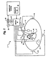
- Fig. 1 is u schematic depiction of a localization system utilized in an electrophysiology study.
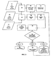
- Fig. 2 is u flowchart that illustrates navigational reference dislodgement detection and mitigation functions according to an embodiment of the present invention.
- the present invention which is preferably practiced in connection with a localization system, automatically detects dislodgement of a navigational reference for the localization system.
- the present disclosure provides methods of automatically correcting for the dislodgment or to guide a user, e.g., a physician, in repositioning the navigational reference at its original location.
- a user e.g., a physician
- the present invention will be described in the context of a cardiac diagnostic or therapeutic procedure, such as an electrophysiology study.
- the invention may be practiced with equal success in any number of other applications, and, accordingly, the illustrative embodiment used herein to describe the invention should not be regarded as limiting.
- Fig. 1 shows a schematic diagram of a localization system 8 for conducting cardiac electrophysiology studies by navigating a cardiac catheter and measuring electrical activity occurring in a heart 10 of a patient 11 and three-dimensionally mapping the electrical activity and/or information related to or representative of the electrical activity so measured.
- System 8 can be used, for example, to create an anatomical model of the patient's heart 10 using one or more electrodes.
- System 8 can also be used to measure electrophysiology date at a plurality of points along a cardiac surface, and store the measured data in association with location information for each measurement point at which the electrophysiology data was measured, for example to create a diagnostic data map of the patient's heart 10.
- localization system 8 determines the location of objects, typically within a three-dimensional space, and expresses those locations as position information determined relative to at least one reference.
- the patient 11 is depicted schematically as an oval.
- Three sets of surface electrodes e.g., patch electrodes
- a surface of the patient 11 defining three generalty orthogonal axes, referred to herein as an x-axis, a y-axis, and a z-axis
- the x-axis surface electrodes 12, 14 are applied to the patient along a first axis, such as on the lateral sides of the thorax region of the patient (e.g., applied to the patent's skin underneath each arm) and may be referred to as the Left and Right electrodes.
- the y-axis electrodes 18, 19 are applied to the patient along a seconde axis generally orthogonal to the x-axis, such as along the inner thigh and neck regions of the patient, and may he referred to as the Left Leg and Neck electrodes.
- the z-axis electrodes 16, 22 are applied along a third axis generally orthogonal to both the x-axis and the y-axis, such as along the sternum and spine of the patient in the thorax region, and may be referred to as the Chest and Back electrodes.
- the heart 10 lies between these pairs of surface electrodes 12/14, 18/19, and 16/22.
- An additional surface reference electrode (e.g., a "belly patch") 21 provides a reference and/or ground electrode for the system 8.
- the belly patch electrode 21 may be an alternative to a fixed intra-cardiac electrode 31, described in further detail below. It should also be appreciated that, in addition, the patient 11 may have most or all of the conventional electrocardiogram (ECG) system leads in place. This ECG information is available to the system 8, although not illustrated in Fig. 1 .
- a representative catheter 13 having at least one electrode 17 is also shown.
- This representative catheter electrode 17 is referred to as the "roving electrode,” “moving electrode,” or “measurement electrode” throughout the specification.
- multiple electrodes on catheter 13, or on multiple such catheters will be used.
- localization system 8 may comprise up to sixty-four electrodes on up to twelve catheters disposed within the heart and/or vasculature of the patient.
- this embodiment is merely exemplary, and any number of electrodes and catheters may he used within the scope of the present invention.
- An optional fixed reference electrode 31 (e.g., attached to a wall of the heart 10) is shown on a second catheter 29.
- this electrode 31 may be stationary (e.g., attached to or near the wall of the heart) or disposed in a fixed spatial relationship with the roving electrode 17, and thus may be referred to as a "navigational reference” or "local reference.”
- the fixed reference electrode 31 may be used in addition or alternatively to the surface reference electrode 21 described above.
- a coronary sinus electrode or other fixed electrode in the heat 10 can be used as a reference for measuring voltages and displacements; that is, as described below, fixed reference electrode 31 may define the origin of a coordinate system.
- Each surface electrode is coupled to the multiplex switch 24, and the pairs of surface electrodes are selected by software running on a computer 20, which couples the electrodes to a signal generator 25.
- the computer 20, for example, may comprise a conventional general-purpose computer, a special-purpose computer, a distributed computer, or any other type of computer.
- the computer 20 may comprise one or more processors, such as a single central processing unit (CPU), or a plurality of processing units, commonly referred to as a parallel processing environment, which may execute instructions to practice the various aspects of the present invention described herein.
- three nominally orthogonal electric fields are generated by a series of driven and sensed electric dipoles (e.g., surface electrode pairs 12/14, 18/19, and 16/22) in order to realize catheter navigation in a biological conductor.
- these orthogonal fields can be decomposed and any pairs of surface electrodes can be driven as dipoles to provide effective electrode triangulation.
- non-orthogonal methodologies add to the flexibility of the system.
- the potentials measured across an intra-cardiac electrode 17 resulting from a predetermined set of drive (source-sink) configurations are combined algebraically to yield the same effective potential as would be obtained by simply driving a uniform current along the orthogonal axes.
- any two of the surface electrodes 12, 14, 16, 18, 19, 22 may be selected as a dipole source and drain with respect to a ground reference, such as belly patch 21, while the unexcited electrodes measure voltage with respect to the ground reference.
- the measurement electrode 17 placed in the heart 10 is exposed to the field from a current pulse and is measured with respect to ground, such as belly patch 21.
- the catheters within the heart may contain multiple electrodes and each electrode potential may be measured.
- at least one electrode may be fixed to the interior surface of the heart to form a fixed reference electrode 31, which is also measured with respect to ground, such us belly patch 21. Data sets from each of the surface electrodes, the internal electrodes, and the virtual electrodes may all be used to determine the location of the measurement electrode 17 or other electrodes within the heart 10.
- the measured voltages may be used to determine the location in three-dimensional space of the electrodes inside the heart, such as the roving electrode 17, relative to a reference location, such as reference electrode 31. That is, the voltages measured at reference electrode 31 may be used to define the origin of a coordinate system, while the voltages measured at roving electrode 17 may be used to express the location of roving electrode 17 relative to the origin.
- the coordinate system is a three-dimensional (x, y, z) Cartesian coordinate system, though the use of other coordinate systems, such as polar, spherical, and cylindrical coordinate systems, is within the scope of the invention.
- the data used to determine the location of the electrode(s) within the heart is measured while the surface electrode pairs impress an electric field on the heart.
- the electrode data may also be used to create a respiration compensation value used to improve the raw location data for the electrode locations as described in U.S. Patent Application Publication No. 2004/0254437 .
- the electrode data may also be used to compensate for changes in the impedance of the body of the patient as described in copending U.S. Patent Application No. 11/227,580, filed on 15 September 2005 .
- the system 8 first selects a set of surface electrodes and then drives them with current pulses. While the current pulses are being delivered, electrical activity, such us the voltages measured at least one of the remaining surface electrodes and in vivo electrodes, is measured and stored. Compensation for artifacts, such as respiration and/or impedance shifting, may be performed as indicated above.
- the localization/mapping system is the EnSite NavXTM navigation and visualization system of St. Jude Medical, Atrial Fibrillation Division, Inc.
- Other localization systems may be used in connection with the present invention, including for example, the CARTO navigation and location system of Biosense Webster, Inc.
- the localization and mapping systems described in the following patents can also be used with the present invention: United States Patent Nos. 6,990,370 ; 6,978,168 ; 6,947,785 ; 6,939,309 ; 6,728,562 ; 6,640,119 ; 5,983,126 ; and 5,697,377
- a navigational reference or local reference such as reference electrode 31, is secured at an initial reference location, preferably internat to the body of patient 11 (block 100).
- the initial reference location is defined as a reference point (e.g., the origin) of a coordinate system that may be used to locate points in space.
- the location of roving electrode 17 (block 110) may be measured relative to the coordinate system having the initial reference location as its origin (block 120), thereby outputting position information that defines the location of roving electrode 17 in the coordinate system that uses the initial reference location as its reference point.
- reference electrodes 31 may become dislodged from the initial reference location during the course of an electrophysiology study, for example if the physician inadvertently tugs on the catheter 29 carrying reference electrode 31, effectively moving the origin of the coordinate system relative to which the position of roving electrode 17 is measured and invalidating any positions of roving electrode 17 measured after the dislodgement. It is desirable, therefore, for a controller to monitor for dislodgement of the navigational reference from the initial reference location, and, if such dislodgement occurs, to generate a signal indicative of the dislodgement, for example to alert the user that a dislodgement has occurred.
- the navigational reference may be coupled to u circuit in order to generate an output signal, which may he monitored for an increase above a threshold indicative of the navigational reference having dislodged from the initial reference location.
- a threshold indicative of the navigational reference having dislodged from the initial reference location.
- the velocity of the navigational reference may be monitored, and, it the velocity of the navigational reference exceeds a preset threshold, one may conclude that the navigational reference has dislodged from the initial reference location; if the navigational reference remains stationary, its velocity is nominally zero.
- an acceleration vector could be monitored, and again, any change that is above a threshold (near zero) would be indicative of movement.
- the threshold may also be implemented as a minimum acceptable value rather than a maximum acceptable value, such that dislodgment may be detected unless the monitored output signal is greater than the minimum acceptable value threshold.
- a far field reference such as belly patch 21, is provided outside the body of patient 11 (block 130).
- the far field reference may be spaced apart from the body. Dislodgment may be detected by monitoring a location of the navigational reference relative to the far field reference (block 140). If the positional relationship between the navigational reference and the far field reference changes beyond a preset threshold, one may conclude that the navigational reference has become dislodged from the initial reference location. This may be accomplished, for example, by coupling both the navigational reference and the far field reference to a circuit in order to generate an output signal, which may he monitored for a signal that is indicative of the navigational reference having dislodged from the initial reference location.
- the output signal generated above is a displacement vector of the navigational reference relative to the for field reference.
- the displacement vector will be nominally 0 (that is, approximately [0, 0, 0]).
- error sources inherent in localization system 8, especially across distances that typically exist between the navigational reference and the far Field reference, and it is desirable to account for these error sources.
- One such error source is DC or very low frequency drift.
- the output signal may be filtered with a high pass filter (block 150) having a cutoff frequency of about 0.01 Hz, and more preferably about 0.001 Hz
- Additional error sources are respiration, patient movement, and cardiac motion (e.g., the beating of the heart 10), which tend to produce variations having frequency components of a fraction of 1 Hz in the case of respiration, to greater than 1 Hz with harmonics ranging to several Hz for cardiac motion.
- a low pass filter (block 160) having a cutoff frequency of about 0.1 Hz to about .5 Hz, and more preferable about 0.15 Hz, and it may be desirable to include a respiration, compensation value as described above (block 170).
- the filtered output signal (block 180) may be monitored for a signal that is indicative of the navigational reference having dislodged from the reference location. As described above, it is desirable that the filtered output signal be a displacement vector that is approximately 0; thus, the filtered output signal may be monitored for a signal with an absolute amplitude that is above a dislodgement threshold (block 190). If such a signal is detected, the user (e.g., a physician or clinician) may he warned (block 200), for example with an audible alarm, a visual cue, or a both an audible alarm and a visual cue.
- a dislodgement threshold block 190
- dislodgement mitigation involves the user (e.g., a physician) repositioning the navigational reference to the initial reference location, thereby re-establishing the original coordinate system
- dislodgement mitigation involves the user (e.g., a physician) repositioning the navigational reference to the initial reference location, thereby re-establishing the original coordinate system
- the user may be provided with guidance, such as positional feedback of the navigational reference or a graphic depiction of the dislodged location of the navigational reference relative to the initial references location (block 240), to assist the user in repositioning and securing the navigational reference to the initial reference location.
- a computer may be utilized to control a servo mechanism, such as that disclosed in United Status application no. 11/647,300, filed 29 December 2006 , to reposition and secure the navigational reference to the initial reference location.
- the navigational reference will reestablish itself in a new, stable position after dislodgement from the initial reference location. If this occurs, it is not necessary to reposition and secure the navigational reference to the initial reference location. Rather, the new, dislodged (or post-dislodgement) location of the navigational reference may be used to define the origin of a new coordinate system.
- a reference adjustment e.g., a coordinate transformation
- the original coordinate system that is, the coordinate system having an origin at the initial reference location
- the new coordinate system that is, the coordinate system having an origin at the post-dislodgement location
- the location of roving electrode 17 may be measured relative to the new coordinate system, and, by applying the reference adjustment (block 220), the location of roving electrode 17 may be defined relative to the original coordinate system such that all location information data for roving electrode 17 may be expressed relative to the original coordinate system having the initial reference location as its reference point (block 230).
- roving electrode 17 may also be utilized to measure electrophysiology information on the surface of heart 10, including, without limitation, voltages, impedances, and complex fractionated electrogram (CFE) information, such as discussed in United States application no. 11/647,276, filed 29 December 2006 . Electrophysiology information may also be measured by the navigational reference, such as reference electrode 31. Since reference electrode 31 and roving electrode 17 are proximate each other, they will experience common noise signals, such as those generated by patient motion, respiration, and cardiac motion.
- CFE complex fractionated electrogram
- the output of roving electrode 17 may be adjusted by compensating for at least one signal that is common to both roving electrode 17 and reference electrode 31, for example by subtracting the output from reference electrode 31 from the output from roving electrode 1 according to the principle of common mode rejection.
- All directional references e.g., upper, lower, upward, downward, left, right, leftward, rightward, top, bottom, above, below, vertical, horizontal, clockwise, and counterclockwise
- Joinder references e.g., attached, couplet, connected, and the like
- Joinder references are to be construed broadly and may include intermediate members between a connection of elements and relative movement between element. As such, joinder references do not necessarily infer that two elements are directly connected and in fixed relation to each other.
Landscapes
- Health & Medical Sciences (AREA)
- Life Sciences & Earth Sciences (AREA)
- Engineering & Computer Science (AREA)
- Surgery (AREA)
- Animal Behavior & Ethology (AREA)
- Veterinary Medicine (AREA)
- Public Health (AREA)
- Biomedical Technology (AREA)
- Heart & Thoracic Surgery (AREA)
- Medical Informatics (AREA)
- Molecular Biology (AREA)
- General Health & Medical Sciences (AREA)
- Physics & Mathematics (AREA)
- Biophysics (AREA)
- Pathology (AREA)
- Human Computer Interaction (AREA)
- Nuclear Medicine, Radiotherapy & Molecular Imaging (AREA)
- Robotics (AREA)
- Computer Vision & Pattern Recognition (AREA)
- Physiology (AREA)
- Psychiatry (AREA)
- Signal Processing (AREA)
- Artificial Intelligence (AREA)
- Cardiology (AREA)
- Measurement And Recording Of Electrical Phenomena And Electrical Characteristics Of The Living Body (AREA)
Claims (4)
- System zum Messen elektrophysiologischer Information unter Verwendung von mehreren Elektroden, mit
einem Lokalisierungssystem (8), das angepasst ist, Orte von Objekten innerhalb eines 3D-Raumes zu bestimmen, und das angepasst ist, Ort-Informationsdaten zu generieren, die Positionsinformationen enthalten, die relativ zu mindestens einer Referenz bestimmt wurden,
einer lokalen Referenz, die zum gesichert werden an einem inneren Referenzort innerhalb eines Körpers eines Patienten konfiguriert ist, wobei die lokale Referenz eine erste Messelektrode (31) aufweist, die zum Generieren eines ersten Messsignal angepasst ist,
einer Fernfeldreferenz (21), die zum gesichert werden an einem externen Referenzort außerhalb des Körpers des Patienten konfiguriert ist,
einer zweiten Messelektrode (17), die zum platziert werden innerhalb des Körpers des Patienten konfiguriert ist, wobei die zweite Messelektrode (17) die zum Generieren eines zweiten Messsignal angepasst ist,
einem Gleichtaktprozessor (20), der zum Vornehmen elektrophysiologischer Messungen unter Verwendung von jeder der ersten und zweiten Messelektrode (31, 17) und zum Justieren der Ausgabe der zweiten Messelektrode (17) durch Entfernen mindestens einer Signalkomponente, die jedem von dem ersten und zweiten Messsignal gemeinsam ist, angepasst ist, und
einem Ausgabeprozessor, der an das Lokalisierungssystem (8) gekoppelt ist und zum Bestimmen eines Ortes der zweiten Messelektrode (17) angepasst ist, und zum Bereitstellen Ort-Informationsdaten für die zweite Messelektrode (17) der angepasst ist, wobei die Ort-Informationsdaten Positionsinformationen enthalten, die relativ zu dem internen Referenzort als ein Referenzpunkt bestimmt wurden,
dadurch gekennzeichnet, dass das System weiter aufweist
eine Steuerung (20), die zum Beobachten einer Entrückung der lokalen Referenz von dem internen Referenzort angepasst ist, und zum Generieren eines Signals, das anzeigt, dass die lokale Referenz von dem lokalen Referenzort entrückt wurde, angepasst ist, und
einem Justierungsprozessor (20), der zum Bestimmen eines entrückten Ortes der lokalen Referenz nachdem die lokale Referenz von dem internen Referenzort entrückt wurde angepasst ist, und der zum Kalkulieren einer Referenzjustierung, die die lokale Referenz, die sich von dem lokalen Referenzort zu dem entrückten Ort bewegt hat, kompensiert, angepasst ist. - System nach Anspruch 1, das weiter einen Servomechanismus zum Repositionieren und Sichern der lokalen Referenz an dem internen Referenzort aufweist.
- System nach Anspruch 1 oder 2, bei dem die Steuerung (20) zum Beobachten einer Geschwindigkeit oder eines Beschleunigungsvektors der lokalen Referenz für eine Anzeige einer Entrückung der lokalen Referenz von dem internen Referenzort angepasst ist.
- System nach Anspruch 1, 2 oder 3, das weiter eine Filterungsschaltung aufweist, die einen Hochpassfilter und einen Tiefpassfilter (27) enthält, wobei die Filterungsschaltung zur Ausgabe eines gefilterten Signal angepasst ist, und wobei die Steuerung (20) zum Beobachten des gefilterten Signals für eine Anzeige einer Entrückung der lokalen Referenz von dem internen Referenzort angepasst ist.
Applications Claiming Priority (2)
| Application Number | Priority Date | Filing Date | Title |
|---|---|---|---|
| US11/647,277 US9220439B2 (en) | 2006-12-29 | 2006-12-29 | Navigational reference dislodgement detection method and system |
| PCT/US2007/088675 WO2008083111A1 (en) | 2006-12-29 | 2007-12-21 | Navigational reference dislodgement detection method and system |
Publications (3)
| Publication Number | Publication Date |
|---|---|
| EP2104449A1 EP2104449A1 (de) | 2009-09-30 |
| EP2104449A4 EP2104449A4 (de) | 2010-12-08 |
| EP2104449B1 true EP2104449B1 (de) | 2013-03-20 |
Family
ID=39584980
Family Applications (1)
| Application Number | Title | Priority Date | Filing Date |
|---|---|---|---|
| EP07869808A Active EP2104449B1 (de) | 2006-12-29 | 2007-12-21 | System zum nachweis des verrutschens einer navigationsreferenz |
Country Status (4)
| Country | Link |
|---|---|
| US (3) | US9220439B2 (de) |
| EP (1) | EP2104449B1 (de) |
| JP (1) | JP5199280B2 (de) |
| WO (1) | WO2008083111A1 (de) |
Families Citing this family (99)
| Publication number | Priority date | Publication date | Assignee | Title |
|---|---|---|---|---|
| US8784336B2 (en) | 2005-08-24 | 2014-07-22 | C. R. Bard, Inc. | Stylet apparatuses and methods of manufacture |
| US7515954B2 (en) | 2006-06-13 | 2009-04-07 | Rhythmia Medical, Inc. | Non-contact cardiac mapping, including moving catheter and multi-beat integration |
| US7794407B2 (en) | 2006-10-23 | 2010-09-14 | Bard Access Systems, Inc. | Method of locating the tip of a central venous catheter |
| US8388546B2 (en) | 2006-10-23 | 2013-03-05 | Bard Access Systems, Inc. | Method of locating the tip of a central venous catheter |
| US9585586B2 (en) | 2006-12-29 | 2017-03-07 | St. Jude Medical, Atrial Fibrillation Division, Inc. | Navigational reference dislodgement detection method and system |
| US9220439B2 (en) | 2006-12-29 | 2015-12-29 | St. Jude Medical, Atrial Fibrillation Division, Inc. | Navigational reference dislodgement detection method and system |
| WO2008126074A2 (en) * | 2007-04-11 | 2008-10-23 | Elcam Medical Agricultural Cooperative Association Ltd. | System and method for accurate placement of a catheter tip in a patient |
| US10751509B2 (en) | 2007-11-26 | 2020-08-25 | C. R. Bard, Inc. | Iconic representations for guidance of an indwelling medical device |
| US9456766B2 (en) | 2007-11-26 | 2016-10-04 | C. R. Bard, Inc. | Apparatus for use with needle insertion guidance system |
| US10524691B2 (en) | 2007-11-26 | 2020-01-07 | C. R. Bard, Inc. | Needle assembly including an aligned magnetic element |
| US10449330B2 (en) | 2007-11-26 | 2019-10-22 | C. R. Bard, Inc. | Magnetic element-equipped needle assemblies |
| US9521961B2 (en) | 2007-11-26 | 2016-12-20 | C. R. Bard, Inc. | Systems and methods for guiding a medical instrument |
| JP5452500B2 (ja) | 2007-11-26 | 2014-03-26 | シー・アール・バード・インコーポレーテッド | カテーテルの血管内留置のための統合システム |
| US9649048B2 (en) | 2007-11-26 | 2017-05-16 | C. R. Bard, Inc. | Systems and methods for breaching a sterile field for intravascular placement of a catheter |
| US8781555B2 (en) | 2007-11-26 | 2014-07-15 | C. R. Bard, Inc. | System for placement of a catheter including a signal-generating stylet |
| US8849382B2 (en) | 2007-11-26 | 2014-09-30 | C. R. Bard, Inc. | Apparatus and display methods relating to intravascular placement of a catheter |
| US8478382B2 (en) | 2008-02-11 | 2013-07-02 | C. R. Bard, Inc. | Systems and methods for positioning a catheter |
| US9901714B2 (en) | 2008-08-22 | 2018-02-27 | C. R. Bard, Inc. | Catheter assembly including ECG sensor and magnetic assemblies |
| US8437833B2 (en) | 2008-10-07 | 2013-05-07 | Bard Access Systems, Inc. | Percutaneous magnetic gastrostomy |
| US8137343B2 (en) * | 2008-10-27 | 2012-03-20 | Rhythmia Medical, Inc. | Tracking system using field mapping |
| CN101836862B (zh) * | 2009-03-16 | 2014-03-26 | 上海微创医疗器械(集团)有限公司 | 人体腔室内壁三维标测方法及其设备和系统 |
| US9532724B2 (en) | 2009-06-12 | 2017-01-03 | Bard Access Systems, Inc. | Apparatus and method for catheter navigation using endovascular energy mapping |
| JP5795576B2 (ja) | 2009-06-12 | 2015-10-14 | バード・アクセス・システムズ,インコーポレーテッド | 心電図(ecg)信号を使用して心臓内またはその近くに血管内デバイスを位置決めするコンピュータベースの医療機器の作動方法 |
| WO2011019760A2 (en) | 2009-08-10 | 2011-02-17 | Romedex International Srl | Devices and methods for endovascular electrography |
| EP2517622A3 (de) | 2009-09-29 | 2013-04-24 | C. R. Bard, Inc. | Stillete zur Verwendung mit Vorrichtungen zur intravaskulären Positionierung eines Katheters |
| WO2011044421A1 (en) | 2009-10-08 | 2011-04-14 | C. R. Bard, Inc. | Spacers for use with an ultrasound probe |
| US8583215B2 (en) * | 2009-11-05 | 2013-11-12 | Biosense Webster (Israel) Ltd. | Reduction of catheter electrode loading |
| US9675302B2 (en) * | 2009-12-31 | 2017-06-13 | Mediguide Ltd. | Prolapse detection and tool dislodgement detection |
| BR112012019354B1 (pt) | 2010-02-02 | 2021-09-08 | C.R.Bard, Inc | Método para localização de um dispositivo médico implantável |
| US9131869B2 (en) * | 2010-05-11 | 2015-09-15 | Rhythmia Medical, Inc. | Tracking using field mapping |
| CA2800813C (en) | 2010-05-28 | 2019-10-29 | C.R. Bard, Inc. | Apparatus for use with needle insertion guidance system |
| US8672837B2 (en) | 2010-06-24 | 2014-03-18 | Hansen Medical, Inc. | Methods and devices for controlling a shapeable medical device |
| US8603004B2 (en) * | 2010-07-13 | 2013-12-10 | St. Jude Medical, Atrial Fibrillation Division, Inc. | Methods and systems for filtering respiration noise from localization data |
| AU2011289513B2 (en) | 2010-08-09 | 2014-05-29 | C.R. Bard, Inc. | Support and cover structures for an ultrasound probe head |
| WO2012024577A2 (en) | 2010-08-20 | 2012-02-23 | C.R. Bard, Inc. | Reconfirmation of ecg-assisted catheter tip placement |
| US9913693B2 (en) * | 2010-10-29 | 2018-03-13 | Medtronic, Inc. | Error correction techniques in surgical navigation |
| WO2012058461A1 (en) | 2010-10-29 | 2012-05-03 | C.R.Bard, Inc. | Bioimpedance-assisted placement of a medical device |
| EP2618730B1 (de) * | 2010-12-17 | 2019-05-15 | St. Jude Medical Atrial Fibrillation Division Inc. | Verfahren und system zur erkennung der löschung einer navigationsreferenz |
| US9414770B2 (en) * | 2010-12-29 | 2016-08-16 | Biosense Webster (Israel) Ltd. | Respiratory effect reduction in catheter position sensing |
| US9901303B2 (en) | 2011-04-14 | 2018-02-27 | St. Jude Medical, Atrial Fibrillation Division, Inc. | System and method for registration of multiple navigation systems to a common coordinate frame |
| US10362963B2 (en) | 2011-04-14 | 2019-07-30 | St. Jude Medical, Atrial Fibrillation Division, Inc. | Correction of shift and drift in impedance-based medical device navigation using magnetic field information |
| US10918307B2 (en) | 2011-09-13 | 2021-02-16 | St. Jude Medical, Atrial Fibrillation Division, Inc. | Catheter navigation using impedance and magnetic field measurements |
| CN105662402B (zh) | 2011-07-06 | 2019-06-18 | C·R·巴德股份有限公司 | 用于插入引导系统的针长度确定和校准 |
| USD699359S1 (en) | 2011-08-09 | 2014-02-11 | C. R. Bard, Inc. | Ultrasound probe head |
| US9211107B2 (en) | 2011-11-07 | 2015-12-15 | C. R. Bard, Inc. | Ruggedized ultrasound hydrogel insert |
| US20130137963A1 (en) * | 2011-11-29 | 2013-05-30 | Eric S. Olson | System and method for automatically initializing or initiating a motion compensation algorithm |
| US9510772B2 (en) | 2012-04-10 | 2016-12-06 | Cardionxt, Inc. | System and method for localizing medical instruments during cardiovascular medical procedures |
| US10588543B2 (en) * | 2012-05-23 | 2020-03-17 | Biosense Webster (Israel), Ltd. | Position sensing using electric dipole fields |
| CN104837413B (zh) | 2012-06-15 | 2018-09-11 | C·R·巴德股份有限公司 | 检测超声探测器上可移除帽的装置及方法 |
| US9820677B2 (en) | 2013-01-03 | 2017-11-21 | St. Jude Medical, Atrial Fibrillation Division, Inc. | Cointegration filter for a catheter navigation system |
| US9057600B2 (en) | 2013-03-13 | 2015-06-16 | Hansen Medical, Inc. | Reducing incremental measurement sensor error |
| US9271663B2 (en) | 2013-03-15 | 2016-03-01 | Hansen Medical, Inc. | Flexible instrument localization from both remote and elongation sensors |
| US9629595B2 (en) * | 2013-03-15 | 2017-04-25 | Hansen Medical, Inc. | Systems and methods for localizing, tracking and/or controlling medical instruments |
| US9014851B2 (en) | 2013-03-15 | 2015-04-21 | Hansen Medical, Inc. | Systems and methods for tracking robotically controlled medical instruments |
| US11020016B2 (en) | 2013-05-30 | 2021-06-01 | Auris Health, Inc. | System and method for displaying anatomy and devices on a movable display |
| EP3035843B1 (de) | 2013-08-22 | 2021-11-03 | AFTx, Inc. | Verfahren, systeme und vorrichtungen zur identifikation und charakterisierung von mit vorhofflimmern assoziierten rotoren |
| US11103174B2 (en) * | 2013-11-13 | 2021-08-31 | Biosense Webster (Israel) Ltd. | Reverse ECG mapping |
| ES2811323T3 (es) | 2014-02-06 | 2021-03-11 | Bard Inc C R | Sistemas para el guiado y la colocación de un dispositivo intravascular |
| GB2524080B (en) * | 2014-03-14 | 2019-03-13 | David Bye Edwin | Measuring and recording body electrical potentials |
| WO2016054256A1 (en) | 2014-09-30 | 2016-04-07 | Auris Surgical Robotics, Inc | Configurable robotic surgical system with virtual rail and flexible endoscope |
| US10973584B2 (en) | 2015-01-19 | 2021-04-13 | Bard Access Systems, Inc. | Device and method for vascular access |
| WO2016179454A1 (en) * | 2015-05-07 | 2016-11-10 | St. Jude Medical, Cardiology Division, Inc. | System and method for detecting sheathing and unsheathing of localization elements |
| CN107750148B (zh) * | 2015-06-19 | 2021-01-01 | 圣犹达医疗用品心脏病学部门有限公司 | 阻抗位移及漂移检测和校正 |
| EP3282995B1 (de) | 2015-06-19 | 2019-04-24 | St. Jude Medical, Cardiology Division, Inc. | Elektromagnetische dynamische registrierung für vorrichtungsnavigation |
| WO2016210325A1 (en) | 2015-06-26 | 2016-12-29 | C.R. Bard, Inc. | Connector interface for ecg-based catheter positioning system |
| JP6824967B2 (ja) | 2015-09-18 | 2021-02-03 | オーリス ヘルス インコーポレイテッド | 管状網のナビゲーション |
| US10143526B2 (en) | 2015-11-30 | 2018-12-04 | Auris Health, Inc. | Robot-assisted driving systems and methods |
| US11000207B2 (en) | 2016-01-29 | 2021-05-11 | C. R. Bard, Inc. | Multiple coil system for tracking a medical device |
| US10376320B2 (en) | 2016-05-11 | 2019-08-13 | Affera, Inc. | Anatomical model generation |
| US10751134B2 (en) * | 2016-05-12 | 2020-08-25 | Affera, Inc. | Anatomical model controlling |
| US10244926B2 (en) | 2016-12-28 | 2019-04-02 | Auris Health, Inc. | Detecting endolumenal buckling of flexible instruments |
| WO2018136733A1 (en) * | 2017-01-19 | 2018-07-26 | St. Jude Medical, Cardiology Division, Inc. | System and method for re-registration of localization system after shift/drift |
| EP3602529B1 (de) * | 2017-03-22 | 2021-12-01 | Boston Scientific Scimed Inc. | Elektrifiziertes anatomisches modell |
| CN108990412B (zh) | 2017-03-31 | 2022-03-22 | 奥瑞斯健康公司 | 补偿生理噪声的用于腔网络导航的机器人系统 |
| US10022192B1 (en) | 2017-06-23 | 2018-07-17 | Auris Health, Inc. | Automatically-initialized robotic systems for navigation of luminal networks |
| WO2019005699A1 (en) | 2017-06-28 | 2019-01-03 | Auris Health, Inc. | ELECTROMAGNETIC FIELD GENERATOR ALIGNMENT |
| EP3644886A4 (de) | 2017-06-28 | 2021-03-24 | Auris Health, Inc. | Detektion von elektromagnetischer verzerrung |
| US11058493B2 (en) | 2017-10-13 | 2021-07-13 | Auris Health, Inc. | Robotic system configured for navigation path tracing |
| US10555778B2 (en) | 2017-10-13 | 2020-02-11 | Auris Health, Inc. | Image-based branch detection and mapping for navigation |
| JP7322026B2 (ja) | 2017-12-14 | 2023-08-07 | オーリス ヘルス インコーポレイテッド | 器具の位置推定のシステムおよび方法 |
| WO2019125964A1 (en) | 2017-12-18 | 2019-06-27 | Auris Health, Inc. | Methods and systems for instrument tracking and navigation within luminal networks |
| US10806365B2 (en) * | 2017-12-26 | 2020-10-20 | Biosense Webster (Israel) Ltd. | Impedance-based position tracking performance using principal component analysis |
| WO2019191144A1 (en) | 2018-03-28 | 2019-10-03 | Auris Health, Inc. | Systems and methods for registration of location sensors |
| WO2019191143A1 (en) | 2018-03-28 | 2019-10-03 | Auris Health, Inc. | Systems and methods for displaying estimated location of instrument |
| CN110831486B (zh) | 2018-05-30 | 2022-04-05 | 奥瑞斯健康公司 | 用于基于定位传感器的分支预测的系统和方法 |
| CN112236083A (zh) | 2018-05-31 | 2021-01-15 | 奥瑞斯健康公司 | 用于导航检测生理噪声的管腔网络的机器人系统和方法 |
| WO2019231891A1 (en) | 2018-05-31 | 2019-12-05 | Auris Health, Inc. | Path-based navigation of tubular networks |
| EP3801348B1 (de) | 2018-05-31 | 2024-05-01 | Auris Health, Inc. | Bildbasierte atemweganalyse und -kartierung |
| CN112261965A (zh) * | 2018-06-11 | 2021-01-22 | 泰尔茂株式会社 | 诊断方法、诊断系统及诊断系统的控制方法 |
| EP3852622A1 (de) | 2018-10-16 | 2021-07-28 | Bard Access Systems, Inc. | Sicherheitsausgerüstete verbindungssysteme und verfahren dafür zur herstellung von elektrischen verbindungen |
| US11918334B2 (en) | 2018-11-07 | 2024-03-05 | St Jude Medical International Holding, Sa.R.L. | Impedance transformation model for estimating catheter locations |
| US11213235B2 (en) | 2018-12-04 | 2022-01-04 | Biosense Webster (Israel) Ltd. | Coronary sinus (CS) catheter movement detection |
| GB201903330D0 (en) * | 2019-03-12 | 2019-04-24 | Epmap System Gmbh & Co Kg | Device for identifying a position of a catheter |
| EP4025921A4 (de) | 2019-09-03 | 2023-09-06 | Auris Health, Inc. | Detektion und kompensation von elektromagnetischer verzerrung |
| EP4084722A4 (de) | 2019-12-31 | 2024-01-10 | Auris Health Inc | Ausrichtungsschnittstellen für perkutanen zugang |
| CN114901194A (zh) | 2019-12-31 | 2022-08-12 | 奥瑞斯健康公司 | 解剖特征识别和瞄准 |
| EP4084720A4 (de) | 2019-12-31 | 2024-01-17 | Auris Health Inc | Ausrichtungstechniken für perkutanen zugang |
| US20220125523A1 (en) * | 2020-10-22 | 2022-04-28 | Biosense Webster (Israel) Ltd. | Signal analysis of movements of a reference electrode of a catheter in a coronary sinus vein |
| WO2023192129A1 (en) * | 2022-03-29 | 2023-10-05 | Noah Medical Corporation | Systems and methods for responsive insertion and retraction of robotic endoscope |
Family Cites Families (34)
| Publication number | Priority date | Publication date | Assignee | Title |
|---|---|---|---|---|
| US5231995A (en) | 1986-11-14 | 1993-08-03 | Desai Jawahar M | Method for catheter mapping and ablation |
| US5280429A (en) | 1991-04-30 | 1994-01-18 | Xitron Technologies | Method and apparatus for displaying multi-frequency bio-impedance |
| US5263493A (en) | 1992-02-24 | 1993-11-23 | Boaz Avitall | Deflectable loop electrode array mapping and ablation catheter for cardiac chambers |
| CA2447239C (en) | 1992-09-23 | 2010-10-19 | Endocardial Therapeutics, Inc. | Endocardial mapping system |
| US5662108A (en) | 1992-09-23 | 1997-09-02 | Endocardial Solutions, Inc. | Electrophysiology mapping system |
| US5335668A (en) | 1993-04-30 | 1994-08-09 | Medical Scientific, Inc. | Diagnostic impedance measuring system for an insufflation needle |
| US5391199A (en) | 1993-07-20 | 1995-02-21 | Biosense, Inc. | Apparatus and method for treating cardiac arrhythmias |
| US6947785B1 (en) | 1993-09-23 | 2005-09-20 | Endocardial Solutions, Inc. | Interface system for endocardial mapping catheter |
| US5730127A (en) | 1993-12-03 | 1998-03-24 | Avitall; Boaz | Mapping and ablation catheter system |
| US5487385A (en) | 1993-12-03 | 1996-01-30 | Avitall; Boaz | Atrial mapping and ablation catheter system |
| US5954665A (en) | 1995-06-07 | 1999-09-21 | Biosense, Inc. | Cardiac ablation catheter using correlation measure |
| US5697377A (en) | 1995-11-22 | 1997-12-16 | Medtronic, Inc. | Catheter mapping system and method |
| IL125757A (en) | 1996-02-15 | 2003-09-17 | Biosense Inc | Medical procedures and apparatus using intrabody probes |
| US5732710A (en) * | 1996-08-09 | 1998-03-31 | R.S. Medical Monitoring Ltd. | Method and device for stable impedance plethysmography |
| US6233477B1 (en) | 1997-10-20 | 2001-05-15 | Irvine Biomedical, Inc. | Catheter system having controllable ultrasound locating means |
| US6115626A (en) | 1998-03-26 | 2000-09-05 | Scimed Life Systems, Inc. | Systems and methods using annotated images for controlling the use of diagnostic or therapeutic instruments in instruments in interior body regions |
| US6129669A (en) | 1998-05-22 | 2000-10-10 | Scimed Life Systems, Inc. | Systems and methods for assessing stability of an ablation electrode in contact with heart tissue |
| US7263397B2 (en) * | 1998-06-30 | 2007-08-28 | St. Jude Medical, Atrial Fibrillation Division, Inc. | Method and apparatus for catheter navigation and location and mapping in the heart |
| US6226542B1 (en) | 1998-07-24 | 2001-05-01 | Biosense, Inc. | Three-dimensional reconstruction of intrabody organs |
| US6468265B1 (en) | 1998-11-20 | 2002-10-22 | Intuitive Surgical, Inc. | Performing cardiac surgery without cardioplegia |
| JP3857569B2 (ja) * | 2001-11-05 | 2006-12-13 | 株式会社日本ヘルスバンク | 心電図伝送機能を具備した電話機 |
| US20050085822A1 (en) * | 2003-10-20 | 2005-04-21 | Thornberry Robert C. | Surgical navigation system component fault interfaces and related processes |
| US7764985B2 (en) | 2003-10-20 | 2010-07-27 | Smith & Nephew, Inc. | Surgical navigation system component fault interfaces and related processes |
| US8046049B2 (en) | 2004-02-23 | 2011-10-25 | Biosense Webster, Inc. | Robotically guided catheter |
| JP4755638B2 (ja) | 2004-03-05 | 2011-08-24 | ハンセン メディカル,インク. | ロボットガイドカテーテルシステム |
| US7974681B2 (en) * | 2004-03-05 | 2011-07-05 | Hansen Medical, Inc. | Robotic catheter system |
| US9782130B2 (en) | 2004-05-28 | 2017-10-10 | St. Jude Medical, Atrial Fibrillation Division, Inc. | Robotic surgical system |
| US20060084863A1 (en) | 2004-10-15 | 2006-04-20 | Jacek Kluzik | Positional verification |
| US7325414B2 (en) | 2004-10-28 | 2008-02-05 | Carrier Corporation | Hybrid tandem compressor system with economizer circuit and reheat function for multi-level cooling |
| US8788044B2 (en) * | 2005-01-21 | 2014-07-22 | Michael Sasha John | Systems and methods for tissue stimulation in medical treatment |
| US7885707B2 (en) | 2005-09-15 | 2011-02-08 | St. Jude Medical, Atrial Fibrillation Division, Inc. | Method of scaling navigation signals to account for impedance drift in tissue |
| US7873410B2 (en) * | 2006-04-26 | 2011-01-18 | Medtronic, Inc. | Implantable medical device with electromechanical delay measurement for lead position and ventricular |
| US7774051B2 (en) | 2006-05-17 | 2010-08-10 | St. Jude Medical, Atrial Fibrillation Division, Inc. | System and method for mapping electrophysiology information onto complex geometry |
| US9220439B2 (en) | 2006-12-29 | 2015-12-29 | St. Jude Medical, Atrial Fibrillation Division, Inc. | Navigational reference dislodgement detection method and system |
-
2006
- 2006-12-29 US US11/647,277 patent/US9220439B2/en active Active
-
2007
- 2007-12-21 JP JP2009544235A patent/JP5199280B2/ja active Active
- 2007-12-21 WO PCT/US2007/088675 patent/WO2008083111A1/en active Application Filing
- 2007-12-21 EP EP07869808A patent/EP2104449B1/de active Active
-
2015
- 2015-11-20 US US14/946,864 patent/US10687725B2/en active Active
-
2020
- 2020-05-14 US US16/874,344 patent/US11766205B2/en active Active
Also Published As
| Publication number | Publication date |
|---|---|
| JP2010514515A (ja) | 2010-05-06 |
| US9220439B2 (en) | 2015-12-29 |
| US20080161681A1 (en) | 2008-07-03 |
| US20200289003A1 (en) | 2020-09-17 |
| US10687725B2 (en) | 2020-06-23 |
| EP2104449A1 (de) | 2009-09-30 |
| JP5199280B2 (ja) | 2013-05-15 |
| US11766205B2 (en) | 2023-09-26 |
| WO2008083111A1 (en) | 2008-07-10 |
| WO2008083111B1 (en) | 2008-10-09 |
| EP2104449A4 (de) | 2010-12-08 |
| US20160331268A1 (en) | 2016-11-17 |
Similar Documents
| Publication | Publication Date | Title |
|---|---|---|
| US11766205B2 (en) | Navigational reference dislodgement detection method and system | |
| US10945632B2 (en) | Navigational reference dislodgement detection method and system | |
| US10278614B2 (en) | System and method for detecting sheathing and unsheathing of localization elements | |
| EP2120700B1 (de) | System und verfahren zur korrektur von inhomogenen feldern | |
| US10799148B2 (en) | System and method for detecting sheathing and unsheathing of localization elements | |
| EP2407118B1 (de) | Systeme zum Filtern von Atemgeräuschen aus Positionsbestimmungsdaten | |
| EP2618730B1 (de) | Verfahren und system zur erkennung der löschung einer navigationsreferenz | |
| US10188314B2 (en) | System and method for detecting sheathing and unsheathing of localization elements | |
| CN115066205A (zh) | 畸变检测的混合方法 |
Legal Events
| Date | Code | Title | Description |
|---|---|---|---|
| PUAI | Public reference made under article 153(3) epc to a published international application that has entered the european phase |
Free format text: ORIGINAL CODE: 0009012 |
|
| 17P | Request for examination filed |
Effective date: 20090717 |
|
| AK | Designated contracting states |
Kind code of ref document: A1 Designated state(s): AT BE BG CH CY CZ DE DK EE ES FI FR GB GR HU IE IS IT LI LT LU LV MC MT NL PL PT RO SE SI SK TR |
|
| DAX | Request for extension of the european patent (deleted) | ||
| A4 | Supplementary search report drawn up and despatched |
Effective date: 20101105 |
|
| 17Q | First examination report despatched |
Effective date: 20110810 |
|
| REG | Reference to a national code |
Ref country code: DE Ref legal event code: R079 Ref document number: 602007029255 Country of ref document: DE Free format text: PREVIOUS MAIN CLASS: A61B0005050000 Ipc: A61B0005060000 |
|
| GRAP | Despatch of communication of intention to grant a patent |
Free format text: ORIGINAL CODE: EPIDOSNIGR1 |
|
| RIC1 | Information provided on ipc code assigned before grant |
Ipc: A61B 5/06 20060101AFI20121018BHEP |
|
| GRAS | Grant fee paid |
Free format text: ORIGINAL CODE: EPIDOSNIGR3 |
|
| GRAA | (expected) grant |
Free format text: ORIGINAL CODE: 0009210 |
|
| AK | Designated contracting states |
Kind code of ref document: B1 Designated state(s): AT BE BG CH CY CZ DE DK EE ES FI FR GB GR HU IE IS IT LI LT LU LV MC MT NL PL PT RO SE SI SK TR |
|
| REG | Reference to a national code |
Ref country code: GB Ref legal event code: FG4D |
|
| REG | Reference to a national code |
Ref country code: CH Ref legal event code: EP |
|
| REG | Reference to a national code |
Ref country code: IE Ref legal event code: FG4D |
|
| REG | Reference to a national code |
Ref country code: AT Ref legal event code: REF Ref document number: 601540 Country of ref document: AT Kind code of ref document: T Effective date: 20130415 |
|
| REG | Reference to a national code |
Ref country code: DE Ref legal event code: R096 Ref document number: 602007029255 Country of ref document: DE Effective date: 20130508 |
|
| PG25 | Lapsed in a contracting state [announced via postgrant information from national office to epo] |
Ref country code: BG Free format text: LAPSE BECAUSE OF FAILURE TO SUBMIT A TRANSLATION OF THE DESCRIPTION OR TO PAY THE FEE WITHIN THE PRESCRIBED TIME-LIMIT Effective date: 20130620 Ref country code: ES Free format text: LAPSE BECAUSE OF FAILURE TO SUBMIT A TRANSLATION OF THE DESCRIPTION OR TO PAY THE FEE WITHIN THE PRESCRIBED TIME-LIMIT Effective date: 20130701 Ref country code: SE Free format text: LAPSE BECAUSE OF FAILURE TO SUBMIT A TRANSLATION OF THE DESCRIPTION OR TO PAY THE FEE WITHIN THE PRESCRIBED TIME-LIMIT Effective date: 20130320 Ref country code: LT Free format text: LAPSE BECAUSE OF FAILURE TO SUBMIT A TRANSLATION OF THE DESCRIPTION OR TO PAY THE FEE WITHIN THE PRESCRIBED TIME-LIMIT Effective date: 20130320 |
|
| REG | Reference to a national code |
Ref country code: AT Ref legal event code: MK05 Ref document number: 601540 Country of ref document: AT Kind code of ref document: T Effective date: 20130320 |
|
| REG | Reference to a national code |
Ref country code: LT Ref legal event code: MG4D |
|
| PG25 | Lapsed in a contracting state [announced via postgrant information from national office to epo] |
Ref country code: LV Free format text: LAPSE BECAUSE OF FAILURE TO SUBMIT A TRANSLATION OF THE DESCRIPTION OR TO PAY THE FEE WITHIN THE PRESCRIBED TIME-LIMIT Effective date: 20130320 Ref country code: FI Free format text: LAPSE BECAUSE OF FAILURE TO SUBMIT A TRANSLATION OF THE DESCRIPTION OR TO PAY THE FEE WITHIN THE PRESCRIBED TIME-LIMIT Effective date: 20130320 Ref country code: GR Free format text: LAPSE BECAUSE OF FAILURE TO SUBMIT A TRANSLATION OF THE DESCRIPTION OR TO PAY THE FEE WITHIN THE PRESCRIBED TIME-LIMIT Effective date: 20130621 Ref country code: SI Free format text: LAPSE BECAUSE OF FAILURE TO SUBMIT A TRANSLATION OF THE DESCRIPTION OR TO PAY THE FEE WITHIN THE PRESCRIBED TIME-LIMIT Effective date: 20130320 |
|
| REG | Reference to a national code |
Ref country code: NL Ref legal event code: VDEP Effective date: 20130320 |
|
| PG25 | Lapsed in a contracting state [announced via postgrant information from national office to epo] |
Ref country code: BE Free format text: LAPSE BECAUSE OF FAILURE TO SUBMIT A TRANSLATION OF THE DESCRIPTION OR TO PAY THE FEE WITHIN THE PRESCRIBED TIME-LIMIT Effective date: 20130320 |
|
| PG25 | Lapsed in a contracting state [announced via postgrant information from national office to epo] |
Ref country code: EE Free format text: LAPSE BECAUSE OF FAILURE TO SUBMIT A TRANSLATION OF THE DESCRIPTION OR TO PAY THE FEE WITHIN THE PRESCRIBED TIME-LIMIT Effective date: 20130320 Ref country code: SK Free format text: LAPSE BECAUSE OF FAILURE TO SUBMIT A TRANSLATION OF THE DESCRIPTION OR TO PAY THE FEE WITHIN THE PRESCRIBED TIME-LIMIT Effective date: 20130320 Ref country code: AT Free format text: LAPSE BECAUSE OF FAILURE TO SUBMIT A TRANSLATION OF THE DESCRIPTION OR TO PAY THE FEE WITHIN THE PRESCRIBED TIME-LIMIT Effective date: 20130320 Ref country code: PT Free format text: LAPSE BECAUSE OF FAILURE TO SUBMIT A TRANSLATION OF THE DESCRIPTION OR TO PAY THE FEE WITHIN THE PRESCRIBED TIME-LIMIT Effective date: 20130722 Ref country code: IS Free format text: LAPSE BECAUSE OF FAILURE TO SUBMIT A TRANSLATION OF THE DESCRIPTION OR TO PAY THE FEE WITHIN THE PRESCRIBED TIME-LIMIT Effective date: 20130720 Ref country code: CZ Free format text: LAPSE BECAUSE OF FAILURE TO SUBMIT A TRANSLATION OF THE DESCRIPTION OR TO PAY THE FEE WITHIN THE PRESCRIBED TIME-LIMIT Effective date: 20130320 Ref country code: RO Free format text: LAPSE BECAUSE OF FAILURE TO SUBMIT A TRANSLATION OF THE DESCRIPTION OR TO PAY THE FEE WITHIN THE PRESCRIBED TIME-LIMIT Effective date: 20130320 Ref country code: NL Free format text: LAPSE BECAUSE OF FAILURE TO SUBMIT A TRANSLATION OF THE DESCRIPTION OR TO PAY THE FEE WITHIN THE PRESCRIBED TIME-LIMIT Effective date: 20130320 |
|
| PG25 | Lapsed in a contracting state [announced via postgrant information from national office to epo] |
Ref country code: CY Free format text: LAPSE BECAUSE OF FAILURE TO SUBMIT A TRANSLATION OF THE DESCRIPTION OR TO PAY THE FEE WITHIN THE PRESCRIBED TIME-LIMIT Effective date: 20130320 Ref country code: PL Free format text: LAPSE BECAUSE OF FAILURE TO SUBMIT A TRANSLATION OF THE DESCRIPTION OR TO PAY THE FEE WITHIN THE PRESCRIBED TIME-LIMIT Effective date: 20130320 |
|
| PLBE | No opposition filed within time limit |
Free format text: ORIGINAL CODE: 0009261 |
|
| STAA | Information on the status of an ep patent application or granted ep patent |
Free format text: STATUS: NO OPPOSITION FILED WITHIN TIME LIMIT |
|
| PG25 | Lapsed in a contracting state [announced via postgrant information from national office to epo] |
Ref country code: DK Free format text: LAPSE BECAUSE OF FAILURE TO SUBMIT A TRANSLATION OF THE DESCRIPTION OR TO PAY THE FEE WITHIN THE PRESCRIBED TIME-LIMIT Effective date: 20130320 |
|
| 26N | No opposition filed |
Effective date: 20140102 |
|
| REG | Reference to a national code |
Ref country code: DE Ref legal event code: R097 Ref document number: 602007029255 Country of ref document: DE Effective date: 20140102 |
|
| REG | Reference to a national code |
Ref country code: CH Ref legal event code: PL |
|
| PG25 | Lapsed in a contracting state [announced via postgrant information from national office to epo] |
Ref country code: LU Free format text: LAPSE BECAUSE OF FAILURE TO SUBMIT A TRANSLATION OF THE DESCRIPTION OR TO PAY THE FEE WITHIN THE PRESCRIBED TIME-LIMIT Effective date: 20131221 Ref country code: MC Free format text: LAPSE BECAUSE OF FAILURE TO SUBMIT A TRANSLATION OF THE DESCRIPTION OR TO PAY THE FEE WITHIN THE PRESCRIBED TIME-LIMIT Effective date: 20130320 |
|
| REG | Reference to a national code |
Ref country code: IE Ref legal event code: MM4A |
|
| PG25 | Lapsed in a contracting state [announced via postgrant information from national office to epo] |
Ref country code: IE Free format text: LAPSE BECAUSE OF NON-PAYMENT OF DUE FEES Effective date: 20131221 Ref country code: CH Free format text: LAPSE BECAUSE OF NON-PAYMENT OF DUE FEES Effective date: 20131231 Ref country code: LI Free format text: LAPSE BECAUSE OF NON-PAYMENT OF DUE FEES Effective date: 20131231 |
|
| PG25 | Lapsed in a contracting state [announced via postgrant information from national office to epo] |
Ref country code: TR Free format text: LAPSE BECAUSE OF FAILURE TO SUBMIT A TRANSLATION OF THE DESCRIPTION OR TO PAY THE FEE WITHIN THE PRESCRIBED TIME-LIMIT Effective date: 20130320 |
|
| PG25 | Lapsed in a contracting state [announced via postgrant information from national office to epo] |
Ref country code: HU Free format text: LAPSE BECAUSE OF FAILURE TO SUBMIT A TRANSLATION OF THE DESCRIPTION OR TO PAY THE FEE WITHIN THE PRESCRIBED TIME-LIMIT; INVALID AB INITIO Effective date: 20071221 |
|
| PG25 | Lapsed in a contracting state [announced via postgrant information from national office to epo] |
Ref country code: MT Free format text: LAPSE BECAUSE OF FAILURE TO SUBMIT A TRANSLATION OF THE DESCRIPTION OR TO PAY THE FEE WITHIN THE PRESCRIBED TIME-LIMIT Effective date: 20130320 |
|
| REG | Reference to a national code |
Ref country code: FR Ref legal event code: PLFP Year of fee payment: 9 |
|
| REG | Reference to a national code |
Ref country code: FR Ref legal event code: PLFP Year of fee payment: 10 |
|
| PG25 | Lapsed in a contracting state [announced via postgrant information from national office to epo] |
Ref country code: IT Free format text: LAPSE BECAUSE OF NON-PAYMENT OF DUE FEES Effective date: 20151221 |
|
| PG25 | Lapsed in a contracting state [announced via postgrant information from national office to epo] |
Ref country code: IT Free format text: LAPSE BECAUSE OF NON-PAYMENT OF DUE FEES Effective date: 20151221 |
|
| PGRI | Patent reinstated in contracting state [announced from national office to epo] |
Ref country code: IT Effective date: 20170710 |
|
| REG | Reference to a national code |
Ref country code: FR Ref legal event code: PLFP Year of fee payment: 11 |
|
| P01 | Opt-out of the competence of the unified patent court (upc) registered |
Effective date: 20230616 |
|
| REG | Reference to a national code |
Ref country code: DE Ref legal event code: R082 Ref document number: 602007029255 Country of ref document: DE Representative=s name: ALPSPITZ IP ALLGAYER UND PARTNER PATENTANWAELT, DE |
|
| PGFP | Annual fee paid to national office [announced via postgrant information from national office to epo] |
Ref country code: GB Payment date: 20231108 Year of fee payment: 17 |
|
| PGFP | Annual fee paid to national office [announced via postgrant information from national office to epo] |
Ref country code: IT Payment date: 20231214 Year of fee payment: 17 Ref country code: FR Payment date: 20231108 Year of fee payment: 17 Ref country code: DE Payment date: 20231108 Year of fee payment: 17 |