EP2104249A1 - Selbstanpassendes dispersionskompensationssystem und verfahren für ein optisches kommunikationsnetz - Google Patents
Selbstanpassendes dispersionskompensationssystem und verfahren für ein optisches kommunikationsnetz Download PDFInfo
- Publication number
- EP2104249A1 EP2104249A1 EP06828422A EP06828422A EP2104249A1 EP 2104249 A1 EP2104249 A1 EP 2104249A1 EP 06828422 A EP06828422 A EP 06828422A EP 06828422 A EP06828422 A EP 06828422A EP 2104249 A1 EP2104249 A1 EP 2104249A1
- Authority
- EP
- European Patent Office
- Prior art keywords
- dispersion
- unit
- information transmission
- control processing
- processing unit
- Prior art date
- Legal status (The legal status is an assumption and is not a legal conclusion. Google has not performed a legal analysis and makes no representation as to the accuracy of the status listed.)
- Granted
Links
Images


Classifications
-
- H—ELECTRICITY
- H04—ELECTRIC COMMUNICATION TECHNIQUE
- H04B—TRANSMISSION
- H04B10/00—Transmission systems employing electromagnetic waves other than radio-waves, e.g. infrared, visible or ultraviolet light, or employing corpuscular radiation, e.g. quantum communication
- H04B10/25—Arrangements specific to fibre transmission
- H04B10/2507—Arrangements specific to fibre transmission for the reduction or elimination of distortion or dispersion
- H04B10/2513—Arrangements specific to fibre transmission for the reduction or elimination of distortion or dispersion due to chromatic dispersion
Definitions
- the present invention relates to optical transmission technology, in particular to an adaptive dispersion compensation system and a method used in optical communication network.
- the optical communication system develops along the trends of high speed, large capacity, long distance and intelligence and so on.
- 160 channels dense wavelength division multiplexing (DMDM) optical communication system with 10 Gb/s speed per channel has been commercialized, and the automatically switched optical network (ASON) system based on intelligent circuit switching has also been commercialized.
- the optical network systems with larger capacity and higher speed (40 Gb/s and above) will appear in the future.
- the intelligent optical network system with optical cross function or optical-add drop multiplexing function will also appear.
- the dispersion and polarization mode dispersion will result in the deterioration of the quality of optical signals, and can decrease the transmission distance.
- measures need to be taken to compensate the dispersion and the polarization mode dispersion.
- a fixed dispersion compensator is used to compensate the dispersion on lines as shown in Fig. 1 .
- dispersion compensation the residual dispersion of the optical signal at the receiving side is ensured to be controlled within the tolerable range of a receiver.
- a dispersion compensation optical fiber module is used as the dispersion compensator.
- the factors such as temperature, pressure and so on can result in the subtle change of the line optical fiber dispersion coefficient, and therefore the real-time change of the dispersion value of the light signal in the optical path will be accumulated continuously with the increase of the total transmission distance, which may result in the signal residual dispersion at receiving side exceeds the tolerable range, and consequently the error performance of the system will be deteriorated.
- the dispersion tolerance of the light source is consequently decreased.
- the dispersion tolerance value is about 1000ps/nm; while for the 40Gb/s optical signal without pre-chirp, the dispersion tolerance value is about 40ps/nm, which only equals to 2km transmission distance of G.652 optical fiber within 1550nm wavelength window. Therefore, for the 40Gb/s system, since the dispersion accommodation value of the light source is small, the subtle change of the line optical fiber dispersion value may possibly cause that the signal residual dispersion at receiving side exceeds the tolerable range, and the system error code performance will be deteriorated accordingly. As described above, the influence to the performance of 40Gb/s system due to the change of the optical fiber dispersion is particularly obvious.
- the reconfigurable optical add/drop multiplexing even the optical cross-connect node will be brought into the optical network.
- the dynamic add/drop multiplexing and the dynamic cross-connect of the optical signals among the optical network nodes will bring the change of the dispersion value of the optical signal in optical path, which may cause the signal residual dispersion at receiving side exceed the tolerable range, and the system error code performance will be deteriorated accordingly.
- the factors show that with the optical network develops towards the directions of high speed, long distance and intelligence, since the change of the dispersion values of lines and the optical network nodes, the signal residual dispersion value at the receiving side is caused to change continuously after the optical signals are transmitted in the lines.
- the adaptive dispersion compensation is necessary for the signals with continuously changeable residual dispersion values. How to realize the adaptive compensation is one of the key issues in the technical field.
- the dispersion adjusting unit of the adaptive dispersion compensation system can be accomplished by using a tunable dispersion compensator.
- the dispersion compensation function of the tunable dispersion compensator can be realized in optical domain and also can be realized in electrical domain.
- the methods to realize the tunable dispersion compensation in optical domain are many, including various methods by using chirped fiber Bragg grating technology, interference technology based on Gires-Tournois etalon and multistage dispersion compensation module connected in series and so on.
- the methods to realize the tunable dispersion compensation in electrical domain are also many. After being processed by photoelectric conversion and linear amplification, the optical signal is sent to an equalization circuit.
- the performances of an equalizer are fed back through detecting the quality of equalized electrical signals and using some a control strategy to realize the adaptive dispersion compensation.
- the equalization circuit used by the dispersion compensation in electrical domain can be FFE (Feed-forward equalizer), DFE (Decision Feedback Equalizer), FDTS (Fixed Delay Tree Search) ,or MLSE (Maximum Likihood Sequence Estimation) and so on, or the combination of the pluralities of methods.
- the adaptive dispersion compensation can be realized by feeding back and controlling the signals.
- the adaptive dispersion compensation function consists of three parts: a performance detecting unit, a control processing unit and a dispersion adjusting unit which are relevant with the dispersion, as shown in Fig. 4 .
- Many methods can be used to realize the adaptive dispersion compensation, but mainly realized at one node.
- the above three units can be located at different nodes. When the three units are located at different nodes, in order to realize the performance of adaptive dispersion compensation, relevant information needs to be transmitted effectively among different nodes.
- a method of interacting information between the performance detecting unit and the control processing unit through a signaling system is described in relevant technology, and is used to realize the adaptive dispersion compensation.
- the performance detecting unit, the control processing unit and the dispersion adjusting unit are not located at a same node.
- the performance detecting unit, the control processing unit and the dispersion adjusting unit which are relevant with the adaptive compensation system can be located at different nodes. Therefore, relevant information needs to be transmitted effectively among different nodes.
- Fig. 1 is the diagram of the traditional optical communication system dispersion compensation method.
- the dispersion compensation fiber module is usually used after the wave is combined and before the wave is dispersed to compensate the dispersion of the multichannel optical signal of a DWDM system.
- two-stage optical amplifiers are usually used, and the dispersion compensation fiber module is arranged between the two-stage amplifiers to realize multichannel dispersion compensation.
- the tunable dispersion compensation of the system consists of the optical domain dispersion compensation and the electrical domain dispersion compensation.
- the adaptive dispersion compensation function is realized by feeding back the signals and controlling the tunable dispersion compensator in optical domain or electrical domain.
- the adaptive dispersion compensation function is realized by feeding back the signals and controlling the tunable dispersion compensator in optical domain or electrical domain.
- Fig. 4 is the functional module diagram with various of adaptive dispersion compensation functions, consisting of three parts: the performance detecting unit, the control processing unit and the dispersion adjusting unit which are relevant with the dispersion.
- the diagram is suitable for the adaptive dispersion compensation module which can be realized at one node.
- the three units can be located at different nodes.
- the three units in order to realize the performance of the adaptive dispersion compensation, relevant information needs to be transmitted effectively among different nodes.
- the present invention mainly aims at providing a adaptive dispersion compensation system and a method used in optical communication network to overcome the defect in prior art that each part of the adaptive dispersion compensator is required to be arranged at the same node.
- the present invention provides a adaptive dispersion compensation system used in optical communication network.
- the adaptive dispersion compensation system comprises at least one performance detecting unit, for detecting relevant performances of the dispersion; at least one control processing unit, for generating control information according to the detected information from the at least one performance detecting unit; at least one dispersion adjusting unit.
- an information transmission unit which is connected among at least one performance detecting unit, at least one control processing unit and at least one dispersion adjusting unit which are arranged at different nodes, the information transmission unit is used for transmitting the detected information from at least one performance detecting unit to at least one control processing unit which is arranged at a different node, and is used for transmitting the control information from at least one control processing unit to at least one dispersion adjusting unit which is arranged at a different node.
- the dispersion adjusting unit can be an tunable dispersion compensator, comprising the tunable dispersion compensator using CFBG (Chirped Fiber Bragg Grating), or the tunable dispersion compensator using G-T etalon interference technology, or the tunable dispersion compensator using microelectronic mechanical system technology, or the tunable dispersion compensator using PLC ring-shaped resonant cavity technology, or the device using multistage fixed dispersion compensator cascade connection technology and using different dispersion compensation value control technology through an optical switch.
- CFBG Compact Fiber Bragg Grating
- G-T etalon interference technology or the tunable dispersion compensator using microelectronic mechanical system technology
- PLC ring-shaped resonant cavity technology or the device using multistage fixed dispersion compensator cascade connection technology and using different dispersion compensation value control technology through an optical switch.
- the dispersion adjusting unit can be an tunable dispersion transmitter.
- the dispersion adjusting unit can be an tunable dispersion receiver.
- the dispersion adjusting unit can be an tunable dispersion compensation receiver, comprising an electric domain tunable dispersion compensation receiver, or an optical domain tunable dispersion compensation receiver or the combination of the two.
- one of at least one performance detecting unit, one of at least one control processing unit corresponding to the performance detecting unit, and one of at least one dispersion adjusting unit corresponding to the performance detecting unit are arranged respectively at different nodes.
- the detected information between the performance detecting unit and the control processing unit is transmitted by the information transmission unit.
- the control information between the control processing unit and the dispersion adjusting unit is transmitted by the information transmission unit.
- one of at least one dispersion adjusting unit and one of at least one control processing unit corresponding to the dispersion adjusting unit are arranged at the same node.
- One of at least one performance detecting unit corresponding to the dispersion adjusting unit is arranged at a different node.
- the detected information between the performance detecting unit and the control processing unit is transmitted by the information transmission unit.
- the control information of the control processing unit is directly transmitted to the dispersion adjusting unit.
- one of at least one performance detecting unit and one of at least one control processing unit corresponding to the performance detecting unit are arranged at the same node.
- One of at least one dispersion adjusting unit corresponding to the performance detecting unit is arranged at a different node.
- the detected information of the performance detecting unit is directly transmitted to the control processing unit.
- the control information between the control processing unit and the dispersion adjusting unit is transmitted by the information transmission unit.
- a plurality of at least one performance detecting unit, a plurality of at least one control processing unit corresponding to the performance detecting unit, and a plurality of at least one dispersion adjusting unit corresponding to the performance detecting unit are respectively arranged at different nodes.
- the detected information between the plurality of the performance detecting unit and the plurality of the control processing unit corresponding to the performance detecting unit respectively is transmitted by the information transmission unit.
- the control information between the plurality of the control processing unit and the plurality of the dispersion adjusting unit corresponding to the control processing unit respectively is transmitted by the information transmission unit.
- both a plurality of at least one performance detecting unit, and a plurality of at least one dispersion adjusting unit corresponding to the performance detecting unit correspond to one of at least one control processing unit and are intensively controlled by a control processing unit.
- the information transmission unit realizes in-band information transmission through the overhead inside the optical path which needs to be compensated.
- the information transmission unit realizes information transmission through the public optical path irrelevant to the optical path which needs to be compensated.
- the information transmission unit realizes information transmission through the combination of the two paths: the overhead inside the optical path which needs to be compensated, and the public optical path irrelevant to the optical path which needs to be compensated.
- the detected information can be the dispersion change information of the optical path which needs to be compensated over the whole optical transmission link.
- the adaptive dispersion compensation system can be suitable for single channel or multichannel.
- the present invention provides a adaptive dispersion compensation method used in optical communication network.
- the adaptive dispersion compensation method comprises the following steps:
- the information transmission unit is used to transmit the detected information from at least one performance detecting unit to at least one control processing unit which is arranged at a different node, and is used to transmit the control information from at least one control processing unit to at least one dispersion adjusting unit which is arranged at a different node.
- the tunable dispersion compensator can be used as the dispersion adjusting unit to compensate the dispersion.
- the information transmission unit realizes in-band information transmission through the overhead inside the optical path which needs to be compensated.
- the information transmission unit realizes information transmission through the public optical path irrelevant to the optical path which needs to be compensated.
- the information transmission unit realizes information transmission through the combination of the two paths: overhead inside the optical path which needs to be compensated and the public optical path irrelevant to the optical path which needs to be compensated.
- the detected information can be the dispersion change information of the optical path which needs to be compensated over the whole optical transmission link.
- the detected information can be the signal error code rate or signal Q factor or the information which reflects signal quality of the optical path which needs to be compensated at the receiving side of the optical transmission link.
- the adaptive dispersion compensation method is suitable for the single channel system or multi-path system.
- the present invention can realize the adaptive dispersion compensation for the multi-path or the single channel system by using the technical proposal under the circumstance that the performance detecting unit, the control processing unit and the dispersion adjusting unit which are relevant to the adaptive dispersion compensation are arranged at different nodes.
- the adaptive dispersion compensation system 10 used in optical communication network comprises: at least one performance detecting unit 20, for detecting dispersion relevant performances; at least one control processing unit, for generating the control information based on the detected information from at least one performance detecting unit 20; at least one dispersion adjusting unit 40, for compensating dispersion based on the control information from at least one control processing unit 30; and an information transmission unit 50, which is connected among at least one performance detecting unit 20, at least one control processing unit 30 and at least one dispersion adjusting unit 40 which are arranged at different nodes, the information transmission unit is used for transmitting the detected information from at least one performance detecting unit 20 to at least one control processing unit 30 which is arranged at a different node, and is used for transmitting the control information from at least one control processing unit 30 to at least one dispersion adjusting unit 40 which is arranged at a different node.
- the dispersion adjusting unit 40 can be an tunable dispersion compensator, comprising the tunable dispersion compensator using CFBG (Chirped Fiber Bragg Grating), or the tunable dispersion compensator using G-T etalon interference technology, or the tunable dispersion compensator using microelectronic mechanical system technology, or the tunable dispersion compensator using PLC ring-shaped resonant cavity technology, or the device using multistage fixed dispersion compensator cascade connection technology and using different dispersion compensation value control technology through an optical switch.
- CFBG Compact Fiber Bragg Grating
- G-T etalon interference technology or the tunable dispersion compensator using microelectronic mechanical system technology
- PLC ring-shaped resonant cavity technology or the device using multistage fixed dispersion compensator cascade connection technology and using different dispersion compensation value control technology through an optical switch.
- the dispersion adjusting unit 40 can be a tunable dispersion transmitter.
- the dispersion adjusting unit 40 can be a tunable dispersion receiver.
- the dispersion adjusting unit 40 can be a tunable dispersion compensation receiver which can be an electric domain tunable dispersion compensation receiver, or an optical domain tunable dispersion compensation receiver or the combination of both.
- one of at least one performance detecting unit 20, one of at least one control processing unit 30 corresponding to the performance detecting unit, and one of at least one dispersion adjusting unit 40 corresponding to the performance detecting unit are arranged respectively at different nodes.
- the detected information between the performance detecting unit 20 and the control processing unit 30 is transmitted by the information transmission unit 50.
- the control information between the control processing unit 30 and the dispersion adjusting unit 40 is transmitted by the information transmission unit 50.
- one of at least one dispersion adjusting unit 40 and one of at least one control processing unit 30 corresponding to the dispersion adjusting unit are arranged at the same node.
- One of at least one performance detecting unit 20 corresponding to the dispersion adjusting unit is arranged at a different node.
- the detected information between the performance detecting unit 20 and the control processing unit 30 is transmitted by the information transmission unit 50.
- the control information of the control processing unit 30 is directly transmitted to the dispersion adjusting unit 40.
- one of at least one performance detecting unit 20 and one of at least one control processing unit 30 corresponding to the performance detecting unit are arranged at the same node.
- One of at least one dispersion adjusting unit 40 corresponding to the performance detecting unit is arranged at a different node.
- the detected information of the performance detecting unit 20 is directly transmitted to the control processing unit 30.
- the control information between the control processing unit 30 and the dispersion adjusting unit 40 is transmitted by the information transmission unit 50.
- a plurality of at least one performance detecting unit 20, a plurality of at least one control processing unit 30 corresponding to the performance detecting unit, and a plurality of at least one dispersion adjusting unit 40 corresponding to the performance detecting unit are respectively arranged at different nodes.
- the detected information between the plurality of the performance detecting unit 20 and the plurality of the control processing unit 30 corresponding to the performance detecing unit respectively is transmitted by the information transmission unit 50.
- the control information between the plurality of the control processing unit 30 and the plurality of the dispersion adjusting unit 40 corresponding to the control processing unit respectively is transmitted by the information transmission unit 50.
- both a plurality of at least one performance detecting unit 20 and a plurality of at least one dispersion adjusting unit 40 corresponding to the performance detecting unit correspond to one of at least one control processing unit 30 and are intensively controlled by a control processing unit 30.
- the information transmission unit 50 realizes in-band information transmission through the overhead inside the optical path which needs to be compensated.
- the information transmission unit 50 realizes information transmission through the public optical path irrelevant to the optical path which needs to be compensated.
- the information transmission unit 50 realizes information transmission through the combination of the two paths: the overhead inside the optical path which needs to be compensated, and the public optical path irrelevant to the optical path which needs to be compensated.
- the detected information can be the dispersion change information of the optical path which needs to be compensated over the whole optical transmission link.
- the adaptive dispersion compensation system can be suitable for single channel or multichannel.
- the adaptive dispersion compensation method used in optical communication network comprises the following steps:
- the information transmission unit is used to transmit the detected information from at least one performance detecting unit to at least one control processing unit which is arranged at a different node, and is used to transmit the control information from at least one control processing unit to at least one dispersion adjusting unit which is arranged at a different node.
- the tunable dispersion compensator can be used as the dispersion adjusting unit to compensate the dispersion.
- the information transmission unit realizes in-band information transmission through the overhead inside the optical path which needs to be compensated.
- the information transmission unit realizes information transmission through the public optical path irrelevant to the optical path which needs to be compensated.
- the information transmission unit realizes information transmission through the combination of the two paths: the overhead inside the optical path which needs to be compensated and the public optical path irrelevant to the optical path which needs to be compensated.
- the detected information can be the dispersion change information of the optical path which needs to be compensated over the whole optical transmission link.
- the detected information can be the signal error code rate or signal Q factor or the information which reflects signal quality of the optical path which needs to be compensated at the receiving side of the optical transmission link.
- the adaptive dispersion compensation method is suitable for the single channel system or multichannel system.
- the present invention relates to a dispersion compensation method used in optical transmission system, more particularly, relates to an apparatus and a method which realize adaptive dispersion compensation.
- the present invention provides a adaptive dispersion compensation method and an apparatus which can compensate system dispersion for the intellectualized optical network in a distributed way.
- the technical solution of the present invention can refer to Fir. 5 to Fig. 11 .
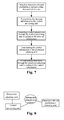
- the present invention comprises the following steps:
- the core content of the present invention is that the information transmission system which shares a same optical path or has independent path is used to transmit the detected or control information relevant to dispersion compensation to realize the adaptive dispersion compensation.
- Fig.5 to Fig.11 are some embodiment of the present invention, which can be applied in single channel system and multichannel system.
- the information among the performance detecting unit, the control processing unit and the dispersion adjusting unit which are arranged at different nodes is transmitted by the information transmission system.
- the control processing unit and the dispersion adjusting unit are arranged at the same node, and the performance detecting unit is arranged at another node.
- the dispersion relevant performance detected information is transmitted to the control processing unit by the information transmission system.
- Fig.9 the control processing unit and the performance detecting unit are arranged at the same node, and the dispersion adjusting unit is arranged at another node.
- the dispersion relevant control information is transmitted from the control processing unit to the dispersion adjusting unit.
- Fig.10 is an example of independent control processing unit. A plurality of control processing units and a plurality of performance detecting units are arranged at the same node and a plurality of dispersion adjusting units are arranged at different nodes.
- the dispersion relevant detected and control information is transmitted among respective control processing unit, performance detecting unit and dispersion adjusting unit by the information transmission system.
- Fig.11 is an illustrative diagram of a centralized control processing unit.
- the control unit can calculate the dispersion value which the tunable dispersion compensator needs to set.
- the relevant information is transmitted to the dispersion adjusting unit to realize the dispersion adaptive regulation.
- the dispersion compensation of the tunable dispersion compensator can be realized by many strategies.
- the simplest strategy is to adjust the dispersion compensation value of the dispersion compensator, ensuring that the residual dispersion value C residual after the dispersion is compensated is controlled within a certain range of C min - C max .
- C residual C Tx - C adj - ⁇ i C Li - ⁇ i C NLi - ⁇ j C ONj C min ⁇ C residual ⁇ C max
- the information transmission system can be realized in many ways, and the basic function thereof is to realize the relevant information transmission among the nodes.
- the physical path of the information transmission system can utilize some overhead inside the optical path which need to be compensated to build an in-band information transmission path, and can also utilize the public optical path which is irrelevant to the optical path which needs to be compensated.
- the information transmission among different nodes can be realized by mature communication protocol and also can be realized by private protocol or method.
- the DCM with fixed dispersion value can be utilized to make coarse dispersion compensation, and the adaptive dispersion compensation system is utilized to compensate the residual dispersion.
- the dispersion detecting unit thereof is arranged at the receiving side, and the dispersion adjusting unit and the control unit thereof are arranged at the transmitting side or at the receiving side.
- the control information needs to be transmitted from the receiving side to the transmitting side.
- STM-256 or the unused overhead bytes of OTU3 can be utilized to transmit dispersion compensation relevant control information.
- the optical supervisory path can be utilized as the physical path.
- Relevant communication protocol can be utilized to realize the transmission of dispersion relevant information.
Landscapes
- Physics & Mathematics (AREA)
- Electromagnetism (AREA)
- Engineering & Computer Science (AREA)
- Computer Networks & Wireless Communication (AREA)
- Signal Processing (AREA)
- Optical Communication System (AREA)
Applications Claiming Priority (1)
| Application Number | Priority Date | Filing Date | Title |
|---|---|---|---|
| PCT/CN2006/003528 WO2008074193A1 (en) | 2006-12-21 | 2006-12-21 | A self adapting dispersion compensation system and method for optical communication network |
Publications (3)
| Publication Number | Publication Date |
|---|---|
| EP2104249A1 true EP2104249A1 (de) | 2009-09-23 |
| EP2104249A4 EP2104249A4 (de) | 2012-08-01 |
| EP2104249B1 EP2104249B1 (de) | 2014-07-02 |
Family
ID=39535973
Family Applications (1)
| Application Number | Title | Priority Date | Filing Date |
|---|---|---|---|
| EP06828422.3A Active EP2104249B1 (de) | 2006-12-21 | 2006-12-21 | Selbstanpassendes dispersionskompensationssystem und verfahren für ein optisches kommunikationsnetz |
Country Status (5)
| Country | Link |
|---|---|
| US (1) | US20090310975A1 (de) |
| EP (1) | EP2104249B1 (de) |
| ES (1) | ES2483245T3 (de) |
| PT (1) | PT2104249E (de) |
| WO (1) | WO2008074193A1 (de) |
Families Citing this family (6)
| Publication number | Priority date | Publication date | Assignee | Title |
|---|---|---|---|---|
| CN101753218B (zh) * | 2009-12-29 | 2014-02-05 | 中兴通讯股份有限公司南京分公司 | 一种自适应色散补偿的方法和装置 |
| CN103154789B (zh) * | 2010-09-03 | 2016-09-21 | Ofs菲特尔有限责任公司 | 色散补偿系统和具有改进的品质因数的色散补偿光纤 |
| US10038503B2 (en) * | 2014-08-13 | 2018-07-31 | Xilinx, Inc. | Adaptive optical channel compensation |
| US11243356B2 (en) * | 2017-07-21 | 2022-02-08 | Telefonaktiebolaget Lm Ericsson (Publ) | Chromatic dispersion compensation |
| US11290184B2 (en) * | 2019-03-01 | 2022-03-29 | Molex, Llc | Switchable dispersion compensating module |
| CN119276373B (zh) * | 2024-12-06 | 2025-02-14 | 国网浙江省电力有限公司杭州供电公司 | 一种基于光纤网络的配电通信网数据恢复方法及系统 |
Family Cites Families (11)
| Publication number | Priority date | Publication date | Assignee | Title |
|---|---|---|---|---|
| AU2000275586A1 (en) * | 2000-01-31 | 2001-08-14 | Sumitomo Electric Industries, Ltd. | Wavelength dispersion compensation module and optical transmission system including the same |
| TW508920B (en) * | 2000-06-01 | 2002-11-01 | Sumitomo Electric Industries | Optical transmission system |
| US20020109879A1 (en) * | 2000-08-23 | 2002-08-15 | Wing So John Ling | Co-channel modulation |
| US20030058494A1 (en) * | 2001-06-27 | 2003-03-27 | Roberts Kim B. | Control of parameters in a global optical controller |
| US20030039013A1 (en) * | 2001-08-27 | 2003-02-27 | Jones David J. | Dynamic dispersion compensation in high-speed optical transmission systems |
| US6776493B1 (en) * | 2002-04-17 | 2004-08-17 | Intel Corporation | Tunable optical dispersion compensator |
| US7283740B2 (en) * | 2002-05-29 | 2007-10-16 | Fujitsu Limited | Optical ring network with optical subnets and method |
| JP4176659B2 (ja) * | 2004-03-03 | 2008-11-05 | 日本電信電話株式会社 | 自動分散補償装置 |
| JP4366225B2 (ja) * | 2004-03-26 | 2009-11-18 | 富士通株式会社 | 分散補償方法及びその装置 |
| JP4713847B2 (ja) * | 2004-04-30 | 2011-06-29 | 富士通株式会社 | 分散補償方法,光伝送システムおよび光伝送装置 |
| JP4554298B2 (ja) * | 2004-08-20 | 2010-09-29 | 富士通株式会社 | 波長分割多重光伝送システム |
-
2006
- 2006-12-21 WO PCT/CN2006/003528 patent/WO2008074193A1/zh not_active Ceased
- 2006-12-21 ES ES06828422.3T patent/ES2483245T3/es active Active
- 2006-12-21 PT PT68284223T patent/PT2104249E/pt unknown
- 2006-12-21 EP EP06828422.3A patent/EP2104249B1/de active Active
-
2009
- 2009-06-18 US US12/487,109 patent/US20090310975A1/en not_active Abandoned
Also Published As
| Publication number | Publication date |
|---|---|
| WO2008074193A1 (en) | 2008-06-26 |
| EP2104249B1 (de) | 2014-07-02 |
| PT2104249E (pt) | 2014-08-25 |
| ES2483245T3 (es) | 2014-08-06 |
| EP2104249A4 (de) | 2012-08-01 |
| US20090310975A1 (en) | 2009-12-17 |
Similar Documents
| Publication | Publication Date | Title |
|---|---|---|
| JP5091739B2 (ja) | 光信号伝送装置 | |
| US20020186432A1 (en) | Architecture for a photonic transport network | |
| JP2006094500A (ja) | 可変光分散補償および可変電子分散補償を有するイコライザ | |
| US20090310975A1 (en) | Adaptive dispersion compensation system and method for optical communication network | |
| US20050191006A1 (en) | Optical switching apparatus and optical switching method | |
| CN101322335B (zh) | 一种自适应色散补偿装置及方法 | |
| US7376353B2 (en) | Method and apparatus for dispersion management in optical mesh networks | |
| Nesset et al. | 10 Gbit/s bidirectional transmission in 1024-way split, 110 km reach, PON system using commercial transceiver modules, super FEC and EDC | |
| AU2005339456B2 (en) | An apparatus and method for selfadapting dispersion compensation | |
| EP1643668B1 (de) | Verfahren und Vorrichtung zur Dispersionsverwaltung in optischen Nachrichtensystemen | |
| US7254342B2 (en) | Method and system for transmitting information in an optical communication system with low signal distortion | |
| EP1680877A2 (de) | Kabelstation für ein optisches untersee-übertragungssystem | |
| CN101005320A (zh) | 光信号再生器和传输系统 | |
| US20110103790A1 (en) | Method and System for Compensating for Optical Impairment in an Optical Signal | |
| US20040247234A1 (en) | Optical bypass method and architecture | |
| JP2006304170A (ja) | Ponシステムおよびponシステムの分散補償方法 | |
| Karasek et al. | Bidirectional repeaterless transmission of 8× 10 GE over 210 km of standard single mode fibre | |
| US20040126119A1 (en) | Method and apparatus for providing a terminal independent interface between a terrestrial optical terminal and an undersea optical transmission path | |
| JP2007295507A (ja) | 光伝送システム及び光中継装置 | |
| EP1883172A1 (de) | Verwaltung der Dispersion in WDM optischen Kommunikationsnetzwerken | |
| Thiele et al. | 7 CWDM—Upgrade | |
| Gosselin et al. | Tutorial on Key Drivers and Technologies for Future Optical Networks |
Legal Events
| Date | Code | Title | Description |
|---|---|---|---|
| PUAI | Public reference made under article 153(3) epc to a published international application that has entered the european phase |
Free format text: ORIGINAL CODE: 0009012 |
|
| 17P | Request for examination filed |
Effective date: 20090703 |
|
| AK | Designated contracting states |
Kind code of ref document: A1 Designated state(s): AT BE BG CH CY CZ DE DK EE ES FI FR GB GR HU IE IS IT LI LT LU LV MC NL PL PT RO SE SI SK TR |
|
| DAX | Request for extension of the european patent (deleted) | ||
| A4 | Supplementary search report drawn up and despatched |
Effective date: 20120703 |
|
| RIC1 | Information provided on ipc code assigned before grant |
Ipc: H04B 10/18 20060101AFI20120627BHEP |
|
| 17Q | First examination report despatched |
Effective date: 20130716 |
|
| REG | Reference to a national code |
Ref country code: DE Ref legal event code: R079 Ref document number: 602006042164 Country of ref document: DE Free format text: PREVIOUS MAIN CLASS: H04B0010180000 Ipc: H04B0010251300 |
|
| RIC1 | Information provided on ipc code assigned before grant |
Ipc: H04B 10/2513 20130101AFI20131203BHEP Ipc: H04B 10/29 20130101ALI20131203BHEP |
|
| GRAP | Despatch of communication of intention to grant a patent |
Free format text: ORIGINAL CODE: EPIDOSNIGR1 |
|
| INTG | Intention to grant announced |
Effective date: 20140129 |
|
| INTG | Intention to grant announced |
Effective date: 20140204 |
|
| GRAS | Grant fee paid |
Free format text: ORIGINAL CODE: EPIDOSNIGR3 |
|
| GRAA | (expected) grant |
Free format text: ORIGINAL CODE: 0009210 |
|
| AK | Designated contracting states |
Kind code of ref document: B1 Designated state(s): AT BE BG CH CY CZ DE DK EE ES FI FR GB GR HU IE IS IT LI LT LU LV MC NL PL PT RO SE SI SK TR |
|
| REG | Reference to a national code |
Ref country code: GB Ref legal event code: FG4D |
|
| REG | Reference to a national code |
Ref country code: CH Ref legal event code: EP |
|
| REG | Reference to a national code |
Ref country code: RO Ref legal event code: EPE |
|
| REG | Reference to a national code |
Ref country code: IE Ref legal event code: FG4D |
|
| REG | Reference to a national code |
Ref country code: ES Ref legal event code: FG2A Ref document number: 2483245 Country of ref document: ES Kind code of ref document: T3 Effective date: 20140806 |
|
| REG | Reference to a national code |
Ref country code: DE Ref legal event code: R096 Ref document number: 602006042164 Country of ref document: DE Effective date: 20140814 |
|
| REG | Reference to a national code |
Ref country code: PT Ref legal event code: SC4A Free format text: AVAILABILITY OF NATIONAL TRANSLATION Effective date: 20140804 |
|
| REG | Reference to a national code |
Ref country code: NL Ref legal event code: T3 |
|
| REG | Reference to a national code |
Ref country code: AT Ref legal event code: REF Ref document number: 700141 Country of ref document: AT Kind code of ref document: T Effective date: 20141215 |
|
| REG | Reference to a national code |
Ref country code: LT Ref legal event code: MG4D |
|
| PG25 | Lapsed in a contracting state [announced via postgrant information from national office to epo] |
Ref country code: BG Free format text: LAPSE BECAUSE OF FAILURE TO SUBMIT A TRANSLATION OF THE DESCRIPTION OR TO PAY THE FEE WITHIN THE PRESCRIBED TIME-LIMIT Effective date: 20141002 Ref country code: GR Free format text: LAPSE BECAUSE OF FAILURE TO SUBMIT A TRANSLATION OF THE DESCRIPTION OR TO PAY THE FEE WITHIN THE PRESCRIBED TIME-LIMIT Effective date: 20141003 Ref country code: CZ Free format text: LAPSE BECAUSE OF FAILURE TO SUBMIT A TRANSLATION OF THE DESCRIPTION OR TO PAY THE FEE WITHIN THE PRESCRIBED TIME-LIMIT Effective date: 20140702 Ref country code: SE Free format text: LAPSE BECAUSE OF FAILURE TO SUBMIT A TRANSLATION OF THE DESCRIPTION OR TO PAY THE FEE WITHIN THE PRESCRIBED TIME-LIMIT Effective date: 20140702 Ref country code: LT Free format text: LAPSE BECAUSE OF FAILURE TO SUBMIT A TRANSLATION OF THE DESCRIPTION OR TO PAY THE FEE WITHIN THE PRESCRIBED TIME-LIMIT Effective date: 20140702 Ref country code: FI Free format text: LAPSE BECAUSE OF FAILURE TO SUBMIT A TRANSLATION OF THE DESCRIPTION OR TO PAY THE FEE WITHIN THE PRESCRIBED TIME-LIMIT Effective date: 20140702 |
|
| PG25 | Lapsed in a contracting state [announced via postgrant information from national office to epo] |
Ref country code: PL Free format text: LAPSE BECAUSE OF FAILURE TO SUBMIT A TRANSLATION OF THE DESCRIPTION OR TO PAY THE FEE WITHIN THE PRESCRIBED TIME-LIMIT Effective date: 20140702 Ref country code: CY Free format text: LAPSE BECAUSE OF FAILURE TO SUBMIT A TRANSLATION OF THE DESCRIPTION OR TO PAY THE FEE WITHIN THE PRESCRIBED TIME-LIMIT Effective date: 20140702 Ref country code: LV Free format text: LAPSE BECAUSE OF FAILURE TO SUBMIT A TRANSLATION OF THE DESCRIPTION OR TO PAY THE FEE WITHIN THE PRESCRIBED TIME-LIMIT Effective date: 20140702 Ref country code: IS Free format text: LAPSE BECAUSE OF FAILURE TO SUBMIT A TRANSLATION OF THE DESCRIPTION OR TO PAY THE FEE WITHIN THE PRESCRIBED TIME-LIMIT Effective date: 20141102 |
|
| REG | Reference to a national code |
Ref country code: DE Ref legal event code: R097 Ref document number: 602006042164 Country of ref document: DE |
|
| PG25 | Lapsed in a contracting state [announced via postgrant information from national office to epo] |
Ref country code: EE Free format text: LAPSE BECAUSE OF FAILURE TO SUBMIT A TRANSLATION OF THE DESCRIPTION OR TO PAY THE FEE WITHIN THE PRESCRIBED TIME-LIMIT Effective date: 20140702 Ref country code: DK Free format text: LAPSE BECAUSE OF FAILURE TO SUBMIT A TRANSLATION OF THE DESCRIPTION OR TO PAY THE FEE WITHIN THE PRESCRIBED TIME-LIMIT Effective date: 20140702 Ref country code: SK Free format text: LAPSE BECAUSE OF FAILURE TO SUBMIT A TRANSLATION OF THE DESCRIPTION OR TO PAY THE FEE WITHIN THE PRESCRIBED TIME-LIMIT Effective date: 20140702 |
|
| PLBE | No opposition filed within time limit |
Free format text: ORIGINAL CODE: 0009261 |
|
| STAA | Information on the status of an ep patent application or granted ep patent |
Free format text: STATUS: NO OPPOSITION FILED WITHIN TIME LIMIT |
|
| 26N | No opposition filed |
Effective date: 20150407 |
|
| PG25 | Lapsed in a contracting state [announced via postgrant information from national office to epo] |
Ref country code: LU Free format text: LAPSE BECAUSE OF FAILURE TO SUBMIT A TRANSLATION OF THE DESCRIPTION OR TO PAY THE FEE WITHIN THE PRESCRIBED TIME-LIMIT Effective date: 20141221 |
|
| REG | Reference to a national code |
Ref country code: CH Ref legal event code: PL |
|
| REG | Reference to a national code |
Ref country code: IE Ref legal event code: MM4A |
|
| PG25 | Lapsed in a contracting state [announced via postgrant information from national office to epo] |
Ref country code: CH Free format text: LAPSE BECAUSE OF NON-PAYMENT OF DUE FEES Effective date: 20141231 Ref country code: IE Free format text: LAPSE BECAUSE OF NON-PAYMENT OF DUE FEES Effective date: 20141221 Ref country code: LI Free format text: LAPSE BECAUSE OF NON-PAYMENT OF DUE FEES Effective date: 20141231 |
|
| PG25 | Lapsed in a contracting state [announced via postgrant information from national office to epo] |
Ref country code: SI Free format text: LAPSE BECAUSE OF FAILURE TO SUBMIT A TRANSLATION OF THE DESCRIPTION OR TO PAY THE FEE WITHIN THE PRESCRIBED TIME-LIMIT Effective date: 20140702 |
|
| REG | Reference to a national code |
Ref country code: FR Ref legal event code: PLFP Year of fee payment: 10 |
|
| PG25 | Lapsed in a contracting state [announced via postgrant information from national office to epo] |
Ref country code: MC Free format text: LAPSE BECAUSE OF FAILURE TO SUBMIT A TRANSLATION OF THE DESCRIPTION OR TO PAY THE FEE WITHIN THE PRESCRIBED TIME-LIMIT Effective date: 20140702 |
|
| PG25 | Lapsed in a contracting state [announced via postgrant information from national office to epo] |
Ref country code: HU Free format text: LAPSE BECAUSE OF FAILURE TO SUBMIT A TRANSLATION OF THE DESCRIPTION OR TO PAY THE FEE WITHIN THE PRESCRIBED TIME-LIMIT; INVALID AB INITIO Effective date: 20061221 Ref country code: TR Free format text: LAPSE BECAUSE OF FAILURE TO SUBMIT A TRANSLATION OF THE DESCRIPTION OR TO PAY THE FEE WITHIN THE PRESCRIBED TIME-LIMIT Effective date: 20140702 |
|
| REG | Reference to a national code |
Ref country code: FR Ref legal event code: PLFP Year of fee payment: 11 |
|
| REG | Reference to a national code |
Ref country code: FR Ref legal event code: PLFP Year of fee payment: 12 |
|
| PGFP | Annual fee paid to national office [announced via postgrant information from national office to epo] |
Ref country code: ES Payment date: 20250116 Year of fee payment: 19 |
|
| PGFP | Annual fee paid to national office [announced via postgrant information from national office to epo] |
Ref country code: NL Payment date: 20251003 Year of fee payment: 20 |
|
| PGFP | Annual fee paid to national office [announced via postgrant information from national office to epo] |
Ref country code: DE Payment date: 20250930 Year of fee payment: 20 |
|
| PGFP | Annual fee paid to national office [announced via postgrant information from national office to epo] |
Ref country code: GB Payment date: 20251001 Year of fee payment: 20 |
|
| PGFP | Annual fee paid to national office [announced via postgrant information from national office to epo] |
Ref country code: PT Payment date: 20251219 Year of fee payment: 20 Ref country code: AT Payment date: 20251126 Year of fee payment: 20 |
|
| PGFP | Annual fee paid to national office [announced via postgrant information from national office to epo] |
Ref country code: IT Payment date: 20251121 Year of fee payment: 20 |
|
| PGFP | Annual fee paid to national office [announced via postgrant information from national office to epo] |
Ref country code: FR Payment date: 20251008 Year of fee payment: 20 |
|
| PGFP | Annual fee paid to national office [announced via postgrant information from national office to epo] |
Ref country code: BE Payment date: 20251003 Year of fee payment: 20 |
|
| PGFP | Annual fee paid to national office [announced via postgrant information from national office to epo] |
Ref country code: RO Payment date: 20251128 Year of fee payment: 20 |