EP2104164A1 - Porous silicon-containing carbon-based composite material, electrode composed of the same and battery - Google Patents
Porous silicon-containing carbon-based composite material, electrode composed of the same and battery Download PDFInfo
- Publication number
- EP2104164A1 EP2104164A1 EP07860378A EP07860378A EP2104164A1 EP 2104164 A1 EP2104164 A1 EP 2104164A1 EP 07860378 A EP07860378 A EP 07860378A EP 07860378 A EP07860378 A EP 07860378A EP 2104164 A1 EP2104164 A1 EP 2104164A1
- Authority
- EP
- European Patent Office
- Prior art keywords
- silicon
- composite material
- based composite
- weight
- containing carbon
- Prior art date
- Legal status (The legal status is an assumption and is not a legal conclusion. Google has not performed a legal analysis and makes no representation as to the accuracy of the status listed.)
- Withdrawn
Links
Images


Classifications
-
- C—CHEMISTRY; METALLURGY
- C01—INORGANIC CHEMISTRY
- C01B—NON-METALLIC ELEMENTS; COMPOUNDS THEREOF; METALLOIDS OR COMPOUNDS THEREOF NOT COVERED BY SUBCLASS C01C
- C01B33/00—Silicon; Compounds thereof
- C01B33/20—Silicates
-
- H—ELECTRICITY
- H01—ELECTRIC ELEMENTS
- H01G—CAPACITORS; CAPACITORS, RECTIFIERS, DETECTORS, SWITCHING DEVICES OR LIGHT-SENSITIVE DEVICES, OF THE ELECTROLYTIC TYPE
- H01G11/00—Hybrid capacitors, i.e. capacitors having different positive and negative electrodes; Electric double-layer [EDL] capacitors; Processes for the manufacture thereof or of parts thereof
- H01G11/22—Electrodes
- H01G11/24—Electrodes characterised by structural features of the materials making up or comprised in the electrodes, e.g. form, surface area or porosity; characterised by the structural features of powders or particles used therefor
-
- H—ELECTRICITY
- H01—ELECTRIC ELEMENTS
- H01G—CAPACITORS; CAPACITORS, RECTIFIERS, DETECTORS, SWITCHING DEVICES OR LIGHT-SENSITIVE DEVICES, OF THE ELECTROLYTIC TYPE
- H01G11/00—Hybrid capacitors, i.e. capacitors having different positive and negative electrodes; Electric double-layer [EDL] capacitors; Processes for the manufacture thereof or of parts thereof
- H01G11/22—Electrodes
- H01G11/30—Electrodes characterised by their material
- H01G11/32—Carbon-based
- H01G11/34—Carbon-based characterised by carbonisation or activation of carbon
-
- H—ELECTRICITY
- H01—ELECTRIC ELEMENTS
- H01M—PROCESSES OR MEANS, e.g. BATTERIES, FOR THE DIRECT CONVERSION OF CHEMICAL ENERGY INTO ELECTRICAL ENERGY
- H01M10/00—Secondary cells; Manufacture thereof
- H01M10/05—Accumulators with non-aqueous electrolyte
- H01M10/052—Li-accumulators
- H01M10/0525—Rocking-chair batteries, i.e. batteries with lithium insertion or intercalation in both electrodes; Lithium-ion batteries
-
- H—ELECTRICITY
- H01—ELECTRIC ELEMENTS
- H01M—PROCESSES OR MEANS, e.g. BATTERIES, FOR THE DIRECT CONVERSION OF CHEMICAL ENERGY INTO ELECTRICAL ENERGY
- H01M4/00—Electrodes
- H01M4/02—Electrodes composed of, or comprising, active material
- H01M4/13—Electrodes for accumulators with non-aqueous electrolyte, e.g. for lithium-accumulators; Processes of manufacture thereof
- H01M4/133—Electrodes based on carbonaceous material, e.g. graphite-intercalation compounds or CFx
-
- H—ELECTRICITY
- H01—ELECTRIC ELEMENTS
- H01M—PROCESSES OR MEANS, e.g. BATTERIES, FOR THE DIRECT CONVERSION OF CHEMICAL ENERGY INTO ELECTRICAL ENERGY
- H01M4/00—Electrodes
- H01M4/02—Electrodes composed of, or comprising, active material
- H01M4/36—Selection of substances as active materials, active masses, active liquids
- H01M4/362—Composites
- H01M4/364—Composites as mixtures
-
- H—ELECTRICITY
- H01—ELECTRIC ELEMENTS
- H01M—PROCESSES OR MEANS, e.g. BATTERIES, FOR THE DIRECT CONVERSION OF CHEMICAL ENERGY INTO ELECTRICAL ENERGY
- H01M4/00—Electrodes
- H01M4/02—Electrodes composed of, or comprising, active material
- H01M4/36—Selection of substances as active materials, active masses, active liquids
- H01M4/38—Selection of substances as active materials, active masses, active liquids of elements or alloys
-
- H—ELECTRICITY
- H01—ELECTRIC ELEMENTS
- H01M—PROCESSES OR MEANS, e.g. BATTERIES, FOR THE DIRECT CONVERSION OF CHEMICAL ENERGY INTO ELECTRICAL ENERGY
- H01M4/00—Electrodes
- H01M4/02—Electrodes composed of, or comprising, active material
- H01M4/36—Selection of substances as active materials, active masses, active liquids
- H01M4/58—Selection of substances as active materials, active masses, active liquids of inorganic compounds other than oxides or hydroxides, e.g. sulfides, selenides, tellurides, halogenides or LiCoFy; of polyanionic structures, e.g. phosphates, silicates or borates
- H01M4/583—Carbonaceous material, e.g. graphite-intercalation compounds or CFx
-
- H—ELECTRICITY
- H01—ELECTRIC ELEMENTS
- H01M—PROCESSES OR MEANS, e.g. BATTERIES, FOR THE DIRECT CONVERSION OF CHEMICAL ENERGY INTO ELECTRICAL ENERGY
- H01M4/00—Electrodes
- H01M4/02—Electrodes composed of, or comprising, active material
- H01M2004/021—Physical characteristics, e.g. porosity, surface area
-
- H—ELECTRICITY
- H01—ELECTRIC ELEMENTS
- H01M—PROCESSES OR MEANS, e.g. BATTERIES, FOR THE DIRECT CONVERSION OF CHEMICAL ENERGY INTO ELECTRICAL ENERGY
- H01M4/00—Electrodes
- H01M4/02—Electrodes composed of, or comprising, active material
- H01M4/36—Selection of substances as active materials, active masses, active liquids
- H01M4/38—Selection of substances as active materials, active masses, active liquids of elements or alloys
- H01M4/386—Silicon or alloys based on silicon
-
- Y—GENERAL TAGGING OF NEW TECHNOLOGICAL DEVELOPMENTS; GENERAL TAGGING OF CROSS-SECTIONAL TECHNOLOGIES SPANNING OVER SEVERAL SECTIONS OF THE IPC; TECHNICAL SUBJECTS COVERED BY FORMER USPC CROSS-REFERENCE ART COLLECTIONS [XRACs] AND DIGESTS
- Y02—TECHNOLOGIES OR APPLICATIONS FOR MITIGATION OR ADAPTATION AGAINST CLIMATE CHANGE
- Y02E—REDUCTION OF GREENHOUSE GAS [GHG] EMISSIONS, RELATED TO ENERGY GENERATION, TRANSMISSION OR DISTRIBUTION
- Y02E60/00—Enabling technologies; Technologies with a potential or indirect contribution to GHG emissions mitigation
- Y02E60/10—Energy storage using batteries
-
- Y—GENERAL TAGGING OF NEW TECHNOLOGICAL DEVELOPMENTS; GENERAL TAGGING OF CROSS-SECTIONAL TECHNOLOGIES SPANNING OVER SEVERAL SECTIONS OF THE IPC; TECHNICAL SUBJECTS COVERED BY FORMER USPC CROSS-REFERENCE ART COLLECTIONS [XRACs] AND DIGESTS
- Y02—TECHNOLOGIES OR APPLICATIONS FOR MITIGATION OR ADAPTATION AGAINST CLIMATE CHANGE
- Y02E—REDUCTION OF GREENHOUSE GAS [GHG] EMISSIONS, RELATED TO ENERGY GENERATION, TRANSMISSION OR DISTRIBUTION
- Y02E60/00—Enabling technologies; Technologies with a potential or indirect contribution to GHG emissions mitigation
- Y02E60/13—Energy storage using capacitors
Definitions
- the present invention relates to a porous silicon-containing carbon-based composite material, an electrode comprising the aforementioned composite material, and a battery comprising the aforementioned electrode.
- lithium as a negative electrode is mainly used alone in the form of a foil. For this reason, there is a problem in that as charge and discharge cycles are repeated, lithium in the form of a branch (dendrite) is deposited, and the deposition causes short circuiting in the positive and negative electrodes. For this reason, the conventional lithium secondary battery has a disadvantage in that the charge and discharge cycle life is reduced.
- silicon and carbon are dispersed in the form of microparticles. For this reason, conductive properties are improved, and the inserting lithium ions to silicon for alloying are uniformized. As a result, the rate of charging and discharging is increased.
- the aforementioned material has suitable cavities, and thereby, volume expansivity occurring at the time of alloying silicon and lithium can be absorbed. For this reason, the amount of carbon required to control expansivity involved in accordance with alloying can be reduced, and thereby, charge capacity can be increased.
- Japanese Unexamined Patent Application, First Publication No. 2004-146104 describes a composite material obtained by mixing silicon powder, vapor grown carbon fiber (VGCF) and graphite. Even if expansion and retraction repeat in accordance with process of charge and discharge cycles, contact between particles can be maintained, an increase of the inner resistance of a negative electrode is controlled, and the initial capacity of a battery can be maintained without disintegration of a conductive network.
- VGCF vapor grown carbon fiber
- Non-patent Documents 1 and 2 have many disadvantages on practical use, such as a reduced initial charge and discharge efficiency, a large loss in potential at the time of discharging lithium from the carbon material, poor charge and discharge cycle characteristics, and the like.
- the composite materials described in the aforementioned Patent Documents 1 and 2 can improve the charge and discharge capacity, but have a disadvantage in that it is necessary to use an expensive process such as a chemical vapor deposition method (CVD method) using benzene as a carbon source, and the like.
- CVD method chemical vapor deposition method
- An objective of the present invention is to obtain a silicon-containing carbon-based composite material which has an increased reversible capacity and a stable charge and discharge cycle characteristic, has a reduced loss in potential at the time of discharging lithium, and can be produced by a simple preparation process, and in particular, is suitable as an electrode for a lithium ion secondary battery, as well as to obtain a battery using the aforementioned composite material as an electrode.
- the aforementioned objective can be achieved by a porous silicon-containing carbon-based composite material obtainable by carbonizing both (1) a silicon metal or a silicon-containing compound and (2) an organic compound containing no silicon and having a softening point or a melting point, in an inert gas or in a vacuum at a temperature ranging from 300 to 1,500°C.
- the softening point or melting point of the aforementioned component (2) is preferably not more than 400°C.
- the aforementioned porous silicon-containing carbon-based composite material is preferably a particulate.
- the maximum particle size thereof is preferably not more than 100 ⁇ m, the BET specific surface area thereof preferably ranges from 0.5 to 500 m 2 / g, and the pore volume preferably ranges from 1.0 ⁇ 10 -5 to 1 cm 3 /g.
- the aforementioned composite material is preferably a material in which the adsorption isotherm of nitrogen is classified into TYPE I defined in IUPAC.
- the aforementioned composite material can be preferably used as a material for forming an electrode, and is, in particular, preferably used as an electrode for a battery.
- a lithium ion secondary battery is particularly preferable.
- the porous silicon-containing carbon-based composite material of the present invention has a high reversible capacity and stable charge and discharge cycle characteristics, and has a reduced loss of potential at the time of discharging lithium, and can be produced by a simple preparation method.
- the porous silicon-containing carbon-based composite material of the present invention is preferably used as a material for forming an electrode, and is, in particular, preferably used as an electrode for a battery.
- the composite material can be preferably used as an electrode for a lithium ion secondary battery.
- the silicon metals or silicon-containing compounds used in the present invention are not particularly limited.
- the silicon metals may be in a monocrystalline, polycrystalline or amorphous silicon, or the like.
- the silicon-containing compounds may be inorgano silicon compounds or organo silicon compounds.
- oxides such as silicon oxide, silicon dioxide and the like; nitrides such as silicon nitride and the like; carbides such as silicon carbide and the like; as well as, oxynitrides, oxycarbides, silicon alloys, metal silicides, and silicates.
- organo silicon compounds examples include organo silicon compounds having a low molecular weight such as silanes, silazanes, siloxanes and the like, as well as, organo silicon polymers or oligomers such as polysilanes, polysilazanes, polysiloxanes and the like.
- organo silicon polymers or oligomers are preferably used as the organo silicon compounds.
- organo silicon compounds having properties of releasing volatile substances by heating hereinafter, referred to as "thermal decomposability" in the present specification
- thermally decomposable organo silicon compounds those having a reduced char yield in a carbonization step described below are preferable.
- the organo silicon compounds may be used alone or in combination with two or more types thereof.
- R 1 to R 5 independently represent a hydrogen atom, a substituted or non-substituted monovalent hydrocarbon group having 1 to 20 carbon atoms, an alkoxy group, a halogen atom, or an acyl group
- a, b, c and d represent 0 or a positive number, with the proviso that a +
- the polysilane represented by the aforementioned average unit formula (I) is composed of at least one unit selected from the structural units represented by (R 1 R 2 R 3 Si), (R 3 R 4 Si), (R 5 Si) and (Si).
- a straight-chain polysilane formed from (R 1 R 2 R 3 Si) and (R 3 R 4 Si) units a cyclic polysilane formed from (R 3 R 4 Si) units; a branched chain polysilane (polysilyn) formed from (R 5 Si) or (Si) units; a polysilane formed from (R 1 R 2 R 3 Si) and (R 5 Si) units; a polysilane formed from (R 1 R 2 R 3 Si) and (Si) units; a polysilane formed from (R 5 Si) and(Si) units; a polysilane formed from (R 3 R 4 Si) and (R 5 Si) units; a polysilane formed from (R 3 R 4 Si) and (R 5 Si) units;
- a monovalent hydrocarbon group selected from the group consisting of an alkyl group, an alkenyl group, an aralkyl group and an aryl group is preferable.
- the alkyl group is preferably one of a straight chain or branched chain alkyl group, a cycloalkyl group, and a cycloalkylene group (an alkyl group formed from a combination of a straight chain or branched chain alkylene group which is preferably a C 1 -C 6 alkylene group such as a methylene group or an ethylene group and a carbon ring which is preferably a C 3 -C 8 ring.
- a straight chain or branched chain alkyl group a straight chain or branched chain C 1 -C 6 alkyl group is preferable.
- a methyl group an ethyl group, an n-propyl group, an isopropyl group, a butyl group, a t-butyl group, a pentyl group, a hexyl group, and the like.
- a methyl group is preferable.
- cycloalkyl group a C 3 -C 6 alkyl group is preferable.
- a cyclopentyl group and a cyclohexyl group are preferable.
- alkenyl group a C 2 -C 12 alkenyl group is preferable, and a C 2 -C 6 alkenyl group is more preferable.
- C 2 -C 6 alkenyl groups mention may be made of a vinyl group, a propenyl group, a butenyl group, a pentenyl group, a hexenyl group, and the like. In particular, a vinyl group is preferable.
- a C 7 -C 12 aralkyl group is preferable and a C 7 -C 12 aralkyl group is more preferable.
- C 7 -C 12 aralkyl groups mention may be made of a benzyl group, a phenethyl group, a phenylpropyl group, and the like. In view of producibility of volatile benzene by means of thermal decomposition, in particular, a benzyl group is preferable.
- aryl group a C 6 -C 12 aryl group is preferable.
- a phenyl group is preferable.
- the aforementioned hydrocarbon group may have a substituent.
- a substituent such as a fluorine atom, a chlorine atom, a bromine atom, an iodine atom, or the like: a hydroxy group; a C 1 -C 6 alkoxy group such as a methoxy group, an ethoxy group, an n-propoxy group, an isopropoxy group, or the like; an amino group; an amide group; a nitro group; an epoxy group; and the like.
- the substituent can bind at any position of a hydrocarbon chain, a saturated or unsaturated ring, and an aromatic ring.
- alkoxy groups for R 1 to R 5 mention may be made of a methoxy group, an ethoxy group, an n-propoxy group, and an isopropoxy group.
- halogen atoms for R 1 to R 5 , mention may be made of a fluorine atom, a chlorine atom, a bromine atom, or an iodine atom.
- acyloxy groups for R 1 to R 5 mention may be made of an acetoxy group.
- the molecular weight of the aforementioned polysilanes is not particularly limited, but a relatively large molecular weight is preferable. More particularly, the weight average molecular weight preferably ranges from 200 to 100,000, more preferably ranges from 300 to 100,000, and, in particular, more preferably ranges from 400 to 50,000. The weight average molecular weight can be determined as a relative value with respect to standard polystyrene in gel permeation chromatography.
- the aforementioned polysilanes can be prepared by means of various known methods. As examples thereof, mention may be made of, for example, a method in which a dehalogenation reaction of a halosilane is carried out in the presence of an alkali metal ( J. Am. Chem. Soc., 110, 124 (1988 ); Macromolecules, 23, 3423 (1990 ); and the like), a method in which an anion polymerization of disilene is carried out ( Macromolecules, 23, 4494 (1990 ) and the like), a method in which a dehalogenation reaction of a halosilane by means of electrode reduction ( J. Chem. Soc., Chem. Commun., 1161 (1990 ); J. Chem.
- the polysilane may be a copolymer with another polymer.
- a copolymer formed from a polysilane unit and a silalkylene (such as silethylene) unit; a copolymer formed from a polysilane unit and a silarylene (such as silphenylene) unit; a copolymer formed from a polysilane unit and a polysilazane unit; a copolymer formed from a polysilane unit and a polysiloxane unit; or the like may be used as a polysiloxane.
- the hydrocarbon group used here has the same meanings as defined in the aforementioned R 1 to R 5 .
- the polysilazane represented by the aforementioned average unit formula (II) is composed of at least one unit selected from the structural units represented by (R 6 R 7 R 8 SiNR 9 ), (R 10 R 11 SiNR 12 ), (R 13 SiNR 14 ), and (SiNR 15 ).
- the preferable number of the repeated structural units represented by (R 6 R 7 R 8 SiNR 9 ), (R 10 R 11 SiNR 12 ), (R 13 SiNR 14 ) and (SiNR 15 ) independently ranges from 2 to 10,000, more preferably ranges from 3 to 1,000, and in particular, preferably ranges from 3 to 500.
- the polysilazanes can be prepared in accordance with known methods in the art.
- the preparation methods for polysilazanes are described in, for example, US Patent No. 4312970 , US Patent No. 4340619 , US Patent No. 4395460 , US Patent No. 4404153 , US Patent No. 4482689 , US Patent No. 4397828 , US Patent No. 4540803 , US Patent No. 4543344 , US Patent No. 4835238 , US Patent No. 4774312 , US Patent No. 4929742 , and US Patent No. 4916200 .
- they are also described in Burns et al., in J. Mater. Sci., 22 (1987), pp 2609 - 2614 .
- the polysilazane may be a copolymer with another polymer.
- a copolymer formed from a polysilazane unit and a silalkylene (such as silethylene) unit; a copolymer formed from a polysilazane unit and a silarylene (such as silphenylene) unit; a copolymer formed from a polysilazane unit and a polysiloxane (such as -(CH 3 ) 2 SiO-) unit; and the like can be used as a polysilazane.
- the molecular weight of the aforementioned polysilazane is not particularly limited, but is preferably relatively large. More particularly, the weight average molecular weight preferably ranges from 200 to 100,000, more preferably ranges from 300 to 100,000, and in particular, more preferably ranges from 400 to 50,000. The weight average molecular weight can be determined as a relative value with respect to standard polystyrene in gel permeation chromatography.
- the hydrocarbon group used here has the same meanings as those defined in the aforementioned R 1 to R 5 .
- the polysiloxane represented by the aforementioned average unit structure (III) is composed of at least one unit selected from the structural units represented by (R 16 R 17 R 18 SiO 1/2 ), (R 19 R 20 SiO 2/2 ), (R 21 SiO 3/2 ) and (SiO 4/2 ).
- the preferable number of repeated structural units represented by (R 16 R 17 R 18 SiO 1/2 ), (R 19 R 20 SiO 2/2 ), (R 21 SiO 3/2 ) and (SiO 4/2 ) independently ranges from 2 to 10,000, more preferably ranges from 3 to 1,000, and in particular, preferably ranges from 3 to 500.
- the polysiloxanes can be prepared by known methods in the art.
- the preparation methods for the polysiloxanes are not particularly limited.
- the polysiloxanes can be prepared by hydrolysis of organochlorosilanes. The aforementioned methods and other methods are described in Noll, Chemistry and Technology of Silicones, Chapter 5 (second edition translated in Germany, Academic Press, 1968 ).
- the polysiloxane may be a copolymer with another polymer.
- the molecular weight of the aforementioned polysiloxane is not particularly limited, but is preferably relatively large. More particularly, the weight average molecular weight preferably ranges from 200 to 100,000, more preferably ranges from 300 to 100,000, and in particular, more preferably ranges from 400 to 50,000. The weight average molecular weight can be determined as a relative value with respect to standard polystyrene in gel permeation chromatography.
- the form of the polysilane, polysilazane, and polysiloxane is not particularly limited, and may be a gas, solid, liquid, or paste form, and the like. In view of handling properties, and the like, a solid form is preferable.
- the curing agent a known curing agent in the art can be used.
- the curing agents mention may be made of, for example, radical precursors such as organic peroxides (dibenzoyl peroxide; bis-p-chlorobenzoyl peroxide; bis-2,4-dichlorobenzoyl peroxide; di-t-butyl peroxide; dicumyl peroxide; t-butyl perbenzoate; 2,5-bis(t-butylperoxy)-2,3-dimethylhexane; and t-butyl peracetate), and the like; platinum-containing materials such as platinum complexes such as H 2 PtCl 6 and ((C 4 H 9 ) 3 P) 2 PtCl 2 , and metal platinum.
- radical precursors such as organic peroxides (dibenzoyl peroxide; bis-p-chlorobenzoyl peroxide; bis-2,4-dichlorobenzoyl peroxide; di
- the curing agent is used in an amount sufficiently effective to cause crosslinking of the organo silicon compound.
- the curing agent is used in an amount ranging from 0.1 to 5.0 wt% and preferably ranging from 0.1 to 2.0 wt% on the basis of the weight of the organo silicon compound.
- the curing agent is used in an amount so that the platinum metal is present in an amount ranging from 1 to 1,000 ppm and preferably ranging from 50 to 150 ppm on the basis of the weight of the organo silicon compound.
- the curing agent is used in order to crosslink the organo silicon compound, depending on the types of the organo silicon compounds.
- the curing agent may not be subjected to a reaction with the organo silicon compound when the aforementioned heat treatment is carried out, but the organo silicon compound may be preliminarily subjected to a crosslinking treatment with a suitable curing agent at room temperature or at a temperature ranging from 50 to 300°C, prior to the aforementioned heat treatment.
- the aforementioned silicon metal or silicon-containing compound may be formed into particulates or pellets by means of a pulverization treatment or a granulation treatment, if necessary.
- the pulverization and granulation methods are not particularly limited, and can be carried out by means of a common pulverizer such as a ball mill, or a common granulator such as pelletizer.
- the average particle size in the case of particulates is not particularly limited, and, for example, ranges from about 0.01 to 5,000 ⁇ m, preferably ranges from about 0.01 to 2,000 ⁇ m, and more preferably ranges from about 0.01 to 500 ⁇ m.
- the average particle size preferably ranges from about 0.01 to 5 ⁇ m.
- the organic compound containing no silicon atoms used in the present invention has a softening point or a melting point, and is not particularly limited as long as the compound is an organic compound which does not contain any silicon atoms.
- the organic compounds having no silicon atoms preferably have thermal decomposability and form carbons by means of the carbonization operation described below.
- the thermally decomposable organic compounds having no silicon preferably have a reduced char yield in the carbonization step described below.
- the organic compounds having no silicon atoms may be used alone or in combination with two or more types thereof. In the case of using two or more types of organic compounds having no silicon atoms in combination, one with a reduced char yield and one with an increased char yield are preferably combined.
- preferable organic compounds having no silicon atoms mention may be made of, for example, saturated or unsaturated straight chain hydrocarbons such as methane, ethane, propane, butane, ethylene, acetylene, pentane, hexane, and the like; saturated or unsaturated cyclic hydrocarbons such as cyclopentane, cyclohexane, cyclopentene, cyclohexene, and the like; saturated or unsaturated monocyclic aromatic compounds such as benzene, toluene, xylene, ethylbenzene, phenol, cresol, nitrobenzene, chlorobenzene, styrene, hexaphenylethane, and the like; saturated heterocyclic compounds such as tetrahydrofuran and the like; unsaturated heterocyclic compounds such as furan, pyrrole, pyridine, and the like; condensed heterocyclic compounds such as coumarone and the
- preferable organic compounds containing no silicon atoms are polystyrene and acenaphthylene.
- a reduced char yield mention may be made of the aforementioned straight chain hydrocarbons, cyclic hydrocarbons, monocyclic aromatic compounds, saturated heterocyclic compounds, unsaturated heterocyclic compounds, condensed heterocyclic compounds, condensed cyclic hydrocarbons, thermoplastic resins and the like.
- the number average molecular weight or weight average molecular weight of the resin used as the organic compound containing no silicon atoms is not particularly limited, and the steric structure thereof is not particularly limited.
- the steric structure thereof is not particularly limited.
- polystyrene one having an atactic, isotactic, or syndiotactic structure can be used.
- the form of the organic compound containing no silicon atoms is not particularly limited, and may be a gas, solid, liquid, or paste form, or the like. In view of handling properties, a solid form is preferable.
- the organic compound containing no silicon atoms in the form of a particulate or a pellet can be obtained by means of a pulverization treatment or a granulation treatment, if necessary.
- the pulverization and granulation methods are not particularly limited, and can be carried out by means of a common pulverizer such as a ball mill, or by means of a common granulator such as a pelletizer.
- the average particle size of the organic compound containing no silicon atoms in the form of a particulate is not particularly limited, and, for example, may range from about 0.1 to 5,000 ⁇ m, preferably range from about 0.1 to 2,000 ⁇ m, and more preferably range from about 0.1 to 500 ⁇ m.
- any other components can also be subjected to a heat treatment.
- the other components mention may be made of, for example, electrical conducting materials, fillers, lubricants, deflocculants, dispersants, and curing agents for the organo silicon compounds.
- the preferable components thereof include electrical conducting materials and curing agents.
- electrical conducting materials mention may be made of acetylene black, ketjen black, graphite, carbon fiber, and carbon nanotube.
- a silicon-containing carbon-based composite material can be obtained by means of a simple method in which the aforementioned component (1) and the aforementioned component (2) are heated at a relatively low temperature to carry out carbonization.
- both of the aforementioned component (1) and the aforementioned component (2) are subjected to a heat treatment (baking) in an inert gas or in a vacuum, at a temperature ranging from 300 to 1,500°C, preferably ranging from 500 to 1,500°C, more preferably ranging from 600 to 1,500°C, and in particular, preferably ranging from 600 to 1,300°C, to carry out carbonization.
- a heat treatment baking in an inert gas or in a vacuum
- the aforementioned component (1) and the aforementioned component (2) may be together present, and the mode for coexistence of the aforementioned components (1) and (2) is not particularly limited. Therefore, for example, the aforementioned component (1) and the aforementioned component (2) may be preliminarily mixed, contacted, or come close to coexist before carbonization. Alternatively, at the time of carbonization, the aforementioned component (1) and the aforementioned component (2) may be mixed, contacted, or come close to coexist. Preferably, the aforementioned component (1) and the aforementioned component (2) are preliminarily mixed, contacted, or come close to coexist before carbonization.
- the mixing mode is not particularly limited, and any dry or wet mixing can be carried out.
- a dry mixing mode for example, preliminarily milled component (1) and preliminarily milled component (2) are mixed in a common mixer, or the aforementioned component (1) and the aforementioned component (2) are placed in a pulverizer and milled, followed by stirring the milled products.
- a wet mixing mode for example, the aforementioned component (1) and the aforementioned component (2) are dissolved or dispersed in a solvent, followed by stirring the solution or dispersion.
- any solvent can be used, and for example, water, an alcohol, a hydrocarbon, an ester, a ketone, or an ether can be used.
- a volatile one which can be easily removed after mixing such as an alcohol, ether, hydrocarbon, or the like is preferable.
- the coexistence ratio of the aforementioned component (1) and the aforementioned component (2) is not particularly limited as long as the coexistent mixture can be carbonized.
- a ratio of 0.1 to 10,000 parts by weight of the aforementioned component (2) with respect to 100 parts by weight of the aforementioned component (1) can be used.
- a ratio of 1 to 5,000 parts by weight, and preferably 5 to 1,000 parts by weight of the aforementioned component (2) with respect to 100 parts by weight of the aforementioned component (1) can be used.
- inert gas examples include, for example, nitrogen, helium, and argon.
- a reducing gas such as a hydrogen gas may be included in the aforementioned inert gas.
- the heating temperature (finally reachable temperature) in the carbonization step ranges from 300 to 1,500°C.
- the lower limit of the temperature is preferably 500°C, more preferably 600°C, and in particular, preferably 700°C.
- the upper limit of the temperature is preferably 1,400°C and in particular, preferably 1,200°C. Any range can be selected between the aforementioned upper limit and lower limit of the temperature. If the finally reachable temperature exceeds the upper limit of the aforementioned range, a rearrangement reaction occurs in the obtained silicon-containing carbon-based composite material, and thereby, the growth of the non-preferable silicon carbide is furthered. On the other hand, if the finally reachable temperature is below the lower limit of the aforementioned range, carbonization is insufficient.
- the aforementioned carbonization step may be carried out by two or more steps. For example, in the first step, heating at a low temperature is carried out, and in the second step or the steps after that, heating at the finally reachable temperature can be carried out. In addition, the aforementioned heating step may be carried out after milling a mixture of the aforementioned component (1) and the aforementioned component (2).
- the aforementioned heat treatment can be carried out in a fixed bed type or fluidized bed type carbonization furnace.
- the heating methods and types of carbonization furnaces are not particularly limited as long as they have a function capable of increasing the temperature to a specified temperature.
- carbonization furnaces mention may be made of, for example, Riedhammer furnace, a tunnel furnace, a single furnace and the like.
- the silicon-containing carbon-based composite material of the present invention obtained via the aforementioned carbonization step (3) is porous, and can be represented by the following average structural formula (IV): Si n C x O y H z (IV) wherein 0 ⁇ n, 0 ⁇ x, 0 ⁇ y, and 0 ⁇ z, 0.5 ⁇ x/n ⁇ 100, 0 ⁇ y/n ⁇ 5, and 0 ⁇ z/n ⁇ 10.
- x/n is preferably more than 1, but less than 30.
- y/n is preferably not less than 0, but less than 3, and more preferably not less than 0, but less than 1.5.
- z/n is preferably not less than 0, but less than 5. If the value of x/n is other than the values within the aforementioned range, lithium ion storage capacity may be extremely reduced, and thereby, an increased reversible capacity may not be obtained, and the charge and discharge cycle characteristics may be reduced.
- a stable coating layer (so-called solid electrolyte interface) may not be formed on the surface of the carbon-based composite material, and the initial charge and discharge efficiency may be reduced.
- the carbon in the silicon-containing carbon-based composite material may have a crystalline structure.
- the crystalline structure may vary depending on the heating temperature and/or the types of the aforementioned component (1) and/or component (2).
- the length for an a-axial direction, La is preferably 0.5 nm or more, but 10 nm or less, is more preferably 0.5 nm or more, but 5 nm or less, and is further preferably 0.5 nm or more, but 2 nm or less.
- the aforementioned La value can be obtained by means of the following equation from the intensity ratio (I D /I G ) of two bands of Raman spectra.
- L ⁇ a 4.4 / I D / I G
- the silicon-containing carbon-based composite material of the present invention can be used as a particulate.
- the silicon-containing carbon-based composite material obtained after the heat treatment is preferably pulverized by means of the aforementioned pulverizer.
- the maximum particle size of the particulates of the silicon-containing carbon-based composite material in this case is preferably 100 ⁇ m or less, and more preferably 50 ⁇ m or less.
- the particulate form of the silicon-containing carbon-based composite material in this case is not particularly limited, and may be a sphere, plate, needle, or fracture form, or the like. In addition, the form may be an indeterminate form by combining the aforementioned forms.
- the silicon-containing carbon-based composite material of the present invention is porous.
- the BET specific surface area thereof is within the range of 0.5 to 500 m 2 /g, preferably within the range of 1 to 400 m 2 /g, more preferably within the range of 1 to 300 m 2 /g, further preferably within the range of 1 to 100 m 2 /g, furthermore preferably within the range of 1 to 50 m 2 /g, and in particular, preferably within the range of 4 to 50 m 2 /g. If the aforementioned BET specific surface area is less than the lower limit of the aforementioned range, an increased reversible capacity may not be obtained.
- the adsorption isotherm of nitrogen is classified into TYPE I among typical 6 types defined in IUPAC. Therefore, the surface area and pore volume can be evaluated by using the value of ⁇ s standardized with an adsorbed amount at 0.4 of the relative pressure of the adsorption isotherm of nitrogen in which a non-porous carbon black or the like is used as a standard adsorptive medium.
- the pore volume obtained by the ⁇ s plotting ranges from 1.0 ⁇ 10 -5 to 1 cm 3 /g, preferably ranges from 1.0 ⁇ 10 -4 to 1.0 ⁇ 10 -1 cm 3 /g, and in particular, preferably ranges from 5.0 ⁇ 10 -4 to 5.0 ⁇ 10 -2 cm 3 /g.
- the aforementioned values are derived from the opening pores exposed to the nitrogen molecules. Therefore, it is believed that the aforementioned values fail to include the information of the pores having a size smaller than the aforementioned molecules or the closed pores such as pores formed between aggregates of crystals on the step of the carbonization.
- the porous structure of the silicon-containing carbon-based composite material of the present invention can also be evaluated by a small-angle X-ray scattering.
- the pores evaluated from the adsorption isotherm of nitrogen target pores opening to the outer surface of the particles.
- scattering angle 2 theta ranges from 0 to 5°
- if there are holes or particles having different electron density in a medium an X-ray scattering phenomenon is observed, and information of the porous structure containing not only opening pores but also latent pores can be obtained.
- the average pore size is preferably within the range of 0.1 to 10 nm, more preferably within the range of 0.1 to 5 nm, and in particular, preferably within the range of 0.2 to 2 nm. If the size of not only opening pores but also latent pores is less than the lower limit of the aforementioned range, an increased reversible capacity may not be obtained. In addition, cycle characteristics may be degraded. On the other hand, if the size exceeds the upper limit of the aforementioned range, density and mechanical strength of the particles may be decreased. In addition, an irreversible capacity due to decomposition of a nonaqueous electrolyte or the like may be increased, and thereby, the initial charge and discharge efficiency may be decreased.
- the porous silicon-containing carbon-based composite material of the present invention has an increased reversible capacity and a stable charge and discharge cycle characteristic, has a reduced loss of potential at the time of discharging lithium, and can be produced by means of a simple preparation process. Therefore, the silicon-containing carbon-based composite material of the present invention can be suitably used as a material for use in an electrode of a battery.
- the silicon-containing carbon-based composite material of the present invention is suitable as a material of a negative electrode of a lithium secondary battery.
- the form of the electrode comprising the silicon-containing carbon-based composite material used in the present invention and the preparation method thereof are not particularly limited.
- an electrode can be produced by a method in which a silicon-containing carbon-based composite material is mixed with a binder to form an electrode; or in which a silicon-containing carbon-based composite material is mixed with a binder and a solvent, the obtained paste is adhered on the collector or is applied on the collector, followed by drying to form an electrode.
- the amount of the paste applied to the collector is not particularly limited, and usually ranges from about 0.3 to 15 mg/cm 2 , and preferably ranges from about 0.5 to 10 mg/cm 2 .
- the thickness of the paste applied on the collector ranges, for example, from about 30 to 500 ⁇ m, and preferably ranges from about 50 to 300 ⁇ m.
- Means for drying after application is not particularly limited. A drying treatment by heating under vacuum is preferable.
- the thickness of the electrode material on the collector after the drying treatment ranges, for example, from about 10 to 300 ⁇ m, and preferably ranges from about 20 to 200 ⁇ m.
- a silicon-containing carbon-based composite material in the form of fibers they are arranged in a mono-axis direction or are formed into a fabric, followed by bundling with a conductive fiber such as metal or conductive polymer or knitting therewith to produce an electrode. In the formation of the electrode, terminals may be combined, if necessary.
- the aforementioned collector is not particularly limited. As examples thereof, mention may be made of mesh, foil or the like of a metal such as copper, nickel, or alloys thereof, or the like.
- binder As examples of the aforementioned binder, mention may be made of, for example, a fluorine-based resin (such as polyvinylidene fluoride, polytetrafluoroethylene, or the like), a styrene-butadiene resin, and the like.
- the usage amount of the binder is not particularly limited. The usage amount thereof may range from about 5 to 30 parts by weight, and preferably ranges from about 5 to 20 parts by weight with respect to 100 parts by weight of the silicon-containing carbon-based composite material.
- the adhesion strength of the silicon-containing carbon-based composite material on the surface of the collector may be impaired, and an insulating layer which may cause an increase in inner electrode resistance may be formed.
- the method for preparing a paste is not particularly limited, and for example, a method in which a silicon-containing carbon-based composite material is mixed with a mixture (or a dispersion) of a binder and an organic solvent may be mentioned.
- a solvent which can dissolve or disperse the binder can be used.
- an organic solvent such as N-methylpyrrolidone, N,N-dimethylformamide, or the like.
- the usage amount of the solvent is not particularly limited as long as a paste can be formed.
- the solvent is used in an amount usually ranging from about 50 to 500 parts by weight, preferably ranging from about 100 to 400 parts by weight, and more preferably ranging from about 100 to 300 parts by weight, with respect to 100 parts by weight of the silicon-containing carbon-based composite material.
- any additives may be added.
- an electrode may be produced by adding a conductive auxiliary agent thereto.
- the usage ratio of the conductive auxiliary agent is not particularly limited.
- the conductive auxiliary agent may be used in an amount ranging from about 5 to 30 parts by weight, and preferably ranging from about 5 to 20 parts by weight, with respect to 100 parts by weight of the silicon-containing carbon-based composite material. If the amount is outside of the aforementioned range, the conductivity may be insufficiently imparted, and the ratio of the silicon-containing carbon-based composite material may be relatively reduced.
- the conductive auxiliary agents mention may be made of, for example, carbon black (such as ketjen black, acetylene black, or the like), carbon fiber, carbon nanotube, and the like.
- the conductive auxiliary agents may be used alone or in combination with two or more types thereof.
- the conductive auxiliary agent can be mixed in a paste containing the silicon-containing carbon-based composite material, the binder, and the solvent.
- a negative electrode activator such as graphite or the like may be added to the electrodes of the present invention.
- the types of the battery comprising the electrode of the present invention and methods for producing the same are not particularly limited.
- batteries mention may be made of a lithium ion primary battery, a lithium ion secondary battery, a capacitor, a hybrid capacitor (redox capacitor), an organic radical battery, or a dual carbon battery.
- a lithium ion secondary battery is preferable.
- the lithium ion secondary battery can be produced in accordance with a common method using constructional elements such as a negative electrode formed from the aforementioned electrode, a positive electrode capable of charging and discharging lithium, an electrolyte, a separator, a collector, a gasket, a closing board, a case and the like.
- the lithium ion secondary battery of the present invention is described in detail with reference to Fig. 1 and Fig. 2 showing the lithium ion secondary batteries prepared in the Examples.
- Fig. 1 is a cross-sectional view showing an example of a lithium ion secondary battery of the present invention prepared in Example.
- the aforementioned lithium ion secondary battery is equipped with a container having a generally cylindrical form.
- molecular sieve 1 is appropriately placed at the bottom of the container, but the molecular sieve is an optional element.
- a separator 4 is provided in the diameter direction of the battery, and a positive electrode 2 and a negative electrode 3 formed from the aforementioned electrode containing the silicon-containing carbon-based composite material are also provided respectively on both sides of said separator.
- collectors 8 At the outer side of said positive electrode 2 and said negative electrode 3, collectors 8, polypropylene plates 5, and polypropylene fillers 6 are successively provided toward the periphery side of the container. Said polypropylene plates 5 and polypropylene fillers 6 are optional elements.
- Said separator 4 is formed by contacting a pair of members having a general plate shape, each member having a height lower than a height of said container, but may be formed from one member.
- Each of said positive electrode 2 and negative electrode 3 contacting said separator 4 is formed from a member having a general plate shape with a size smaller than that of said separator 4, and said positive electrode 2 and negative electrode 3 are provided by facing each other via said separator 4.
- Said collectors 8 contacting the outer side of each of said positive electrode 2 and said negative electrode 3 have a height higher than that of said container and are formed from a pair of members of a general plate shape. The leading end parts thereof stick out from said container.
- Said polypropylene plates 5 contacting the outer side of said collectors 8 are formed from a pair of members with a general plate shape having a generally same height as that of said separator 4.
- polypropylene fillers 6 are provided with a gap, and are formed from a pair of members with a generally semi-circular column shape (partially column shape), having a generally same height as that of said separator 4.
- an electrolyte 7 is stored, and only the leading end parts of said collectors 8 stick out from the liquid surface of said electrolyte 7.
- the usage amount of said electrolyte 7 can be reduced.
- Fig. 2 is a general, exploded perspective view of a button-shaped battery which is another example of a lithium ion secondary battery of the present invention prepared in the Examples.
- an insulating packing 10, a positive electrode 11, separators 12, a negative electrode 13 formed from said electrode containing the silicon-containing carbon-based composite material, and a collector 14 are successively placed in a case 9 having a hollow cylinder shape with an opening at the upper face and a bottom, from the lower end part to the upper end part of the case so that all the aforementioned members have a coaxial core.
- Said insulating packing 10 is formed so as to have a ring shape with a size generally equal to the outer circumference of said case 9, and said case 9 is equipped with said insulating packing 10.
- Said positive electrode 11 is formed to have a size slightly smaller than the inner circumference of said case 9.
- said separators 12 are formed by a pair of general disc-shaped members with the general same size as that of the inner circumference of said case 9, but may be formed by one disc shaped member.
- An electrolyte is impregnated in said separators 12.
- Said negative electrode 13 is formed in a general disc shape having the general same size as that of said positive electrode 11, and is positioned so as to oppose to said positive electrode 11 via said separators 12.
- Said collector 14 is formed in a general disc shape with the general same size as that of said negative electrode 13, and is attached tightly to said negative electrode 13.
- Said collector 14 is composed of a copper foil, nickel mesh, a metal gauze or the like.
- a closing plate 15 in the form of a cover having an opening at the lower face with a size slightly larger than that of said case 9 is placed on said case 9. Thereby, a lithium ion secondary battery can be formed.
- Said positive electrodes 2, 11 in the lithium ion secondary batteries shown in Fig. 1 and Fig. 2 are not particularly limited, and for example, can be composed of a positive electrode collector, a positive electrode activator, a conductive material, or the like.
- positive electrode collectors mention may be made of, for example, aluminum and the like.
- positive electrode activators examples include, for example, a calcogen metal product having a layer structure such as TiS 2 , MoS 3 , NbSe 3 , FeS, VS 2 , VSe 2 , and the like; a metal oxide such as CoO 2 , Cr 3 O 5 , TiO 2 , CuO, V 3 O 6 , Mo 3 O, V 2 O 5 ( ⁇ P 2 O 5 ), Mn 2 O( ⁇ Li 2 O), LiCoO 2 , LiNiO 2 , LiMn 2 O 4 or the like.
- the preferable positive electrode activator is a lithium composite oxide such as LiCoO 2 , LiNiO 2 , LiMn 2 O 4 or the like.
- the positive electrode activators may be used alone or in combination with two or more types thereof.
- the conductive materials the same ones as described above can be mentioned.
- the electrolytes contained in the lithium ion secondary batteries shown in Fig. 1 and Fig. 2 are not particularly limited, and known electrolytes can be used.
- a solution obtained by dissolving an electrolyte in an organic solvent as an electrolyte a nonaqueous lithium ion secondary battery can be produced.
- electrolytes mention may be made of, for example, lithium salts such as LiPF 6 , LiClO 4 , LiBF 4 , LiClF 4 , LiAsF 6 , LiSbF 6 , LiAlO 4 , LiAlCl 4 , LiCl, Lil and the like.
- organic solvents mention may be made of, for example, aprotic solvents such as carbonates (such as propylene carbonate, ethylene carbonate, diethyl carbonate, and the like), lactones (such as gamma-butyrolactone and the like), linear ethers (such as 1,2-dimethoxyethane, dimethyl ether, diethyl ether and the like), cyclic ethers (such as tetrahydrofuran, 2-methyltetrahydrofuran, dioxolan, 4-methyldioxolan, and the like), sulforanes (such as sulforane and the like), sulfoxides (such as dimethylsulfoxide and the like), nitriles (such as acetonitrile, propionitrile, benzonitrile, and the like), amides (such as N,N-dimethylformamide, N,N-dimethylacetamide and the like), polyoxyalkylene glycols
- the organic solvents may be used alone or in combination with two or more types thereof.
- concentration of the electrolyte ranges, for example, from about 0.3 to 5 mol, preferably ranges from about 0.3 to 5 mol, and more preferably ranges from about 0.8 to 1.5, with respect to 1 L of the electrolyte.
- Said separators 4, 12 in the lithium ion secondary batteries shown in Fig. 1 and Fig. 2 are not particularly limited.
- Known separators such as polyolefin-based porous membranes such as porous polypropylene nonwoven fabric, porous polyethylene nonwoven fabric and the like can be used.
- the lithium ion secondary batteries of the present invention are not limited to those shown in Fig. 1 and Fig. 2 .
- various forms such as laminate form, pack form, button form, gum form, assembled battery form, a square form and the like can be applied.
- the lithium secondary batteries of the present invention are preferably used as batteries of mobile microelectronics such as video cameras, personal computers, word processors, radio-cassette recorders, mobile phones, and the like by utilizing characteristics of high energy density, increased capacity, and lightweight.
- the charge and discharge characteristics of the lithium ion secondary battery using the silicon-containing carbon-based composite material of the present invention was measured as described below.
- HJR-110mSM6, HJ1001SM8A or HJ1010mSM8A, manufactured by Hokuto Denko Corporation was used, and both charging and discharging were carried out with a constant current.
- the current was set to a current value of 0.1 C which is a tenth with respect to 372 mAh of a theoretical capacity of graphite per gram of the silicon-containing carbon-based composite material.
- charging was set as a capacity until the battery voltage was reduced to 0 V.
- Discharging was set as a capacity until the battery voltage reached 3 V.
- the current value was gradually increased from 0.1 C to 3.0 C.
- the reversible capacity was the discharged capacity at the first time, and the initial charge and discharge efficiency at the first time was the ratio of the discharged capacity to the charged capacity in the first cycle. The capacity maintaining ratio after the cycle tests was indicated by the charged capacity after the cycle with respect to the charged capacity at the first time.
- a boat made of alumina with an SSA-S grade was placed in a boat made of alumina with an SSA-S grade.
- the aforementioned boat was set at the central part of a furnace made of quartz in the form of a tube having a length of about 100 cm and an inner diameter of about 4 cm.
- the inner circumstance of said tubular furnace was maintained for 5 minutes at reduced pressure, and then returned to normal pressure with high purity argon (99.999%). This operation was repeated three times in total.
- high purity argon was being supplied thereto with a flow rate of 100 ml/min, the temperature was increased at a rate of 5°C/min, and baking was carried out for one hour at 1,000°C.
- a silicon-containing carbon-based composite material was obtained.
- the obtained silicon-containing carbon-based composite material was pulverized by means of a ball mill made of zirconia for about 3 hours in air, followed by classifying by means of a sieve made of stainless steel with a #300 mesh.
- a silicon-containing carbon-based composite material in the form of particulates having a maximum particle size of 50 ⁇ m was obtained.
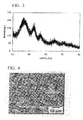
- An X-ray diffraction pattern and a scanning electron micrograph of the obtained silicon-containing carbon-based composite material are respectively shown in Fig. 3 and Fig. 4 .
- the results of elemental analysis of the obtained silicon-containing carbon-based composite material are shown in Table 1.
- the results obtained from an adsorption isotherm of nitrogen are shown in Table 2.
- ketjen black 6.94 parts by weight of ketjen black was added to 107.58 parts by weight of the aforementioned silicon-containing carbon-based composite material, followed by mixing in a mortar for 15 minutes. Subsequently, 12.00 parts by weight of polyvinylidene fluoride was added thereto, and the mixture was further mixed for 15 minutes. Subsequently, N-methyl-2-pyrrolidone as a solvent was added thereto, and thereby, a slurry was formed. Subsequently, the slurry was applied on a copper foil roll by means of a doctor blade method, and thereby, an electrode having a thickness of about 250 ⁇ m was prepared. The electrode obtained above was subjected to vacuum drying for not less than 12 hours at 110°C. Thereby, a negative polar body having a thickness of about 30 ⁇ m was prepared.
- a lithium ion secondary battery having the structure shown in Fig. 1 was prepared.
- a metal lithium was used as electrode 1
- a propylene nonwoven fabric was used as separator 2
- the aforementioned negative polar body was used as negative electrode 3
- a mixed solvent obtained by dissolving lithium perchlorate in a ratio of 1 mol/L in a mixture (1:1 volume ratio) of ethylene carbonate and diethyl carbonate was used.
- evaluation of battery characteristics of the lithium ion secondary battery was carried out. The measurement of constant current charge and discharge was carried out with a current value of 0.095 mA.
- the characteristics of the battery of Example 1 are shown in Table 2 and Fig. 5 .
- Example 2 The same processes as described in Example 1 were carried out, with the exception of using 6.42 g of the aforementioned precursor polymer.
- An X-ray diffraction pattern and a scanning electron micrograph of the silicon-containing carbon-based composite material in the form of particulates having a maximum particle size of 50 ⁇ m are respectively shown in Fig. 6 and Fig. 7 .
- the results of elemental analysis of the obtained silicon-containing carbon-based composite material are shown in Table 1.
- the results obtained from an adsorption isotherm of nitrogen and Raman spectra are shown in Table 2.
- Example 2 The same processes as described in Example 1 were carried out, with the exception of adding 10.73 parts by weight of ketjen black and 10.50 parts by weight of polyvinylidene fluoride to 112.13 parts by weight of the aforementioned silicon-containing carbon-based composite material.
- a lithium ion secondary battery having the structure shown in Fig. 1 was prepared. The same evaluation as described in Example 1 was carried out, with the exception of carrying out the measurement of constant current charge and discharge with a current value of 0.16 mA. The characteristics of the battery of Example 2 are shown in Table 2 and Fig. 8 .
- the obtained carbonaceous material was pulverized by means of a ball mill made of zirconia for about 3 hours in air, followed by classifying by means of a sieve made of stainless steel with a #300 mesh.
- 0.93 parts by weight of the aforementioned carbonaceous material was placed in a boat made of alumina with an SSA-S grade, and the boat was placed at the central part of a furnace made of alumina in the form of a tube having a length of about 100 cm and an inner diameter of about 4 cm.
- high purity argon (99.999%) was supplied to the tubular furnace for 3 hours with a flow rate of 100 ml/min.
- Example 2 The same processes as described in Example 1 were carried out, with the exception of adding 8.81 parts by weight of ketjen black and 9.00 parts by weight of polyvinylidene fluoride to 106.82 parts by weight of the aforementioned silicon-containing carbon-based composite material.
- a lithium ion secondary battery having the structure shown in Fig. 2 was prepared. The same evaluation as described in Example 1 was carried out, with the exception of carrying out the measurement of constant current charge and discharge with a current value of 0.19 mA. The characteristics of the battery of Example 3 are shown in Table 2 and Fig. 12 .
- Example 3 The same processes as described in Example 1 were carried out, with the exception of adding 14.32 parts by weight of ketjen black and 13.72 parts by weight of polyvinylidene fluoride to 150.9 parts by weight of the aforementioned silicon-containing carbon-based composite material obtained in Example 3.
- a lithium ion secondary battery having the structure shown in Fig. 2 was prepared.
- the same evaluation as described in Example 1 was carried out, with the exception of using a mixed solvent obtained by dissolving lithium hexafluorophosphate in a ratio of 1 mol/L in a mixture (1:1 volume ratio) of ethylene carbonate and diethyl carbonate as an electrolyte, and carrying out the measurement of constant current charge and discharge with a current value of 0.18 mA.
- the characteristics of the battery of Example 4 are shown in Table 2 and Fig. 13 .
- Example 3 The same processes as described in Example 3 were carried out, with the exception of using 13.55 parts by weight of the aforementioned precursor polymer, classifying the obtained carbonaceous material with a #2,000 mesh, and using 1.00 parts by weight of the carbonaceous material for the final baking.
- An X-ray diffraction pattern of the obtained silicon-containing carbon-based composite material is shown in Fig. 14 .
- results obtained from an adsorption isotherm of nitrogen and a Raman spectrum are shown in Table 2.
- Example 2 The same processes as described in Example 1 were carried out, with the exception of adding 9.28 parts by weight of ketjen black and 9.34 parts by weight of polyvinylidene fluoride to 106.55 parts by weight of the aforementioned silicon-containing carbon-based composite material.
- a lithium ion secondary battery having the structure shown in Fig. 2 was prepared.
- the same evaluation as described in Example 4 was carried out, with the exception of carrying out the measurement of constant current charge and discharge with a current value of 0.19 mA.
- the characteristics of the battery of Example 5 are shown in Table 2, Fig. 15 and Fig. 16 .
- Example 3 The same processes as described in Example 3 were carried out, with the exception of using 12.11 parts by weight of the aforementioned precursor polymer, classifying the obtained carbonaceous material with a #2,000 mesh, and using 0.55 parts by weight of the carbonaceous material for the final baking.
- the results obtained from an adsorption isotherm of nitrogen and a Raman spectrum are shown in Table 2.
- Example 2 The same processes as described in Example 1 were carried out, with the exception of adding 11.81 parts by weight of ketjen black and 23.94 parts by weight of polyvinylidene fluoride to 201.01 parts by weight of the aforementioned silicon-containing carbon-based composite material.
- a lithium ion secondary battery having the structure shown in Fig. 2 was prepared. The same evaluation as described in Example 4 was carried out, with the exception of carrying out the measurement of constant current charge and discharge with a current value of 0.17 mA. The characteristics of the battery of Example 6 are shown in Table 2 and Fig. 17 .
- Example 5 After the carbonaceous material obtained in Example 5 was classified with a #500 mesh, and was further classified with a #2,000 mesh, the remaining material on the mesh was used. In addition, the same processes as described in Example 3 were carried out, with the exception of using 1.05 parts by weight of the carbonaceous material for the final baking. An x-ray diffraction pattern of the obtained silicon-containing carbon-based composite material is shown in Fig. 18 . In addition, the results obtained from an adsorption isotherm of nitrogen and a Raman spectrum are shown in Table 2.
- Example 2 The same processes as described in Example 1 were carried out, with the exception of adding 9.33 parts by weight of ketjen black and 9.61 parts by weight of polyvinylidene fluoride to 106.92 parts by weight of the aforementioned silicon-containing carbon-based composite material.
- a lithium ion secondary battery having the structure shown in Fig. 2 was prepared.
- the same evaluation as described in Example 4 was carried out, with the exception of carrying out the measurement of constant current charge and discharge with a current value of 0.11 mA.
- the characteristics of the battery of Example 7 are shown in Table 2, Fig. 19 and Fig. 20 .
- the precursor polymer prepared in Example 5 was used.
- Example 7 The carbonaceous material obtained after classification in Example 7 was used. The same processes as described in Example 3 were carried out, with the exception of using 1.03 parts by weight of the carbonaceous material for the final baking at 900°C. An X-ray diffraction pattern of the obtained silicon-containing carbon-based composite material is shown in Fig. 21 . In addition, the results obtained from an adsorption isotherm of nitrogen and a Raman spectrum are shown in Table 2.
- Example 2 The same processes as described in Example 1 were carried out, with the exception of adding 9.40 parts by weight of ketjen black and 9.50 parts by weight of polyvinylidene fluoride to 107.43 parts by weight of the aforementioned silicon-containing carbon-based composite material.
- a lithium ion secondary battery having the structure shown in Fig. 2 was prepared. The same evaluation as described in Example 4 was carried out, with the exception of carrying out the measurement of constant current charge and discharge with a current value of 0.24 mA. The characteristics of the battery of Example 8 are shown in Table 2 and Fig. 22 .
- Example 7 The carbonaceous material obtained after classification in Example 7 was used. The same processes as described in Example 3 were carried out, with the exception of using 0.96 parts by weight of the carbonaceous material for the final baking at 800°C. An X-ray diffraction pattern of the obtained silicon-containing carbon-based composite material is shown in Fig. 23 . In addition, the results obtained from a Raman spectrum are shown in Table 2. It was difficult to measure an adsorption isotherm of nitrogen of the obtained silicon-containing carbon-based composite material.
- Example 2 The same processes as described in Example 1 were carried out, with the exception of adding 9.27 parts by weight of ketjen black and 9.46 parts by weight of polyvinylidene fluoride to 107.89 parts by weight of the aforementioned silicon-containing carbon-based composite material.
- a lithium ion secondary battery having the structure shown in Fig. 2 was prepared. The same processes as described in Example 4 were carried out, with the exception of carrying out the measurement of constant current charge and discharge with a current value of 0.11 mA. The characteristics of the battery of Example 9 are shown in Table 2 and Fig. 24 .
- Example 2 The same processes as described in Example 1 were carried out, with the exception of adding 9.52 parts by weight of ketjen black and 9.56 parts by weight of polyvinylidene fluoride to 107.11 parts by weight of the aforementioned silicon-containing carbon-based composite material.
- a lithium ion secondary battery having the structure shown in Fig. 2 was prepared.
- the same evaluation as described in Example 4 was carried out, with the exception of carrying out the measurement of constant current charge and discharge with a current value of 0.11 mA.
- the characteristics of the battery of Example 10 are shown in Table 2, Fig. 26 and Fig. 27 .
- Example 2 The same processes as described in Example 1 were carried out, with the exception of adding 9.43 parts by weight of ketjen black and 9.37 parts by weight of polyvinylidene fluoride to 107.42 parts by weight of the aforementioned silicon-containing carbon-based composite material.
- a lithium ion secondary battery having the structure shown in Fig. 2 was prepared.
- the same evaluation as described in Example 4 was carried out, with the exception of carrying out the measurement of constant current charge and discharge with a current value of 0.17 mA.
- the characteristics of the battery of Example 11 are shown in Table 2, Fig. 29 and Fig. 30 .
- the precursor polymer prepared in Example 5 was used.
- Example 5 The carbonaceous material obtained in Example 5 which was classified with a #500 mesh was used. The same processes as described in Example 3 were carried out, with the exception of using 1.04 parts by weight of the carbonaceous material for the final baking. The results obtained from a Raman spectrum are shown in Table 2.
- Example 2 The same processes as described in Example 1 were carried out, with the exception of adding 9.38 parts by weight of ketjen black and 9.34 parts by weight of polyvinylidene fluoride to 106.68 parts by weight of the aforementioned silicon-containing carbon-based composite material.
- a lithium ion secondary battery having the structure shown in Fig. 2 was prepared. The same processes as described in Example 4 were carried out, with the exception of carrying out the measurement of constant current charge and discharge with a current value of 0.15 mA. The characteristics of the battery of Example 12 are shown in Table 2 and Fig. 31 .
- the aforementioned precursor polymer in an amount of 4.36 parts by weight, was used, and the obtained carbonaceous material was classified with a #300 mesh.
- the same processes as described in Example 3 were carried out, with the exception of using 0.99 parts by weight of the carbonaceous material for the final baking.
- An X-ray diffraction pattern of the obtained silicon-containing carbon-based composite material is shown in Fig. 32 .
- the results obtained from an adsorption isotherm of nitrogen and a Raman spectrum are shown in Table 2.
- Example 2 The same processes as described in Example 1 were carried out, with the exception of adding 9.54 parts by weight of ketjen black and 9.18 parts by weight of polyvinylidene fluoride to 107.65 parts by weight of the aforementioned silicon-containing carbon-based composite material.
- a lithium ion secondary battery having the structure shown in Fig. 2 was prepared. The same processes as described in Example 4 were carried out, with the exception of carrying out the measurement of constant current charge and discharge with a current value of 0.19 mA. The characteristics of the battery of Example 13 are shown in Table 2 and Fig. 33 .
- the aforementioned precursor polymer in an amount of 4.45 parts by weight, was used, and the obtained carbonaceous material was classified with a #300 mesh.
- the same processes as described in Example 3 were carried out, with the exception of using 1.03 parts by weight of the carbonaceous material for the final baking.
- An X-ray diffraction pattern of the obtained silicon-containing carbon-based composite material is shown in Fig. 34 .
- the results obtained from an adsorption isotherm of nitrogen and a Raman spectrum are shown in Table 2.
- Example 2 The same processes as described in Example 1 were carried out, with the exception of adding 9.66 parts by weight of ketjen black and 9.62 parts by weight of polyvinylidene fluoride to 108.69 parts by weight of the aforementioned silicon-containing carbon-based composite material.
- a lithium ion secondary battery having the structure shown in Fig. 2 was prepared. The same processes as described in Example 4 were carried out, with the exception of carrying out the measurement of constant current charge and discharge with a current value of 0.19 mA. The characteristics of the battery of Example 14 are shown in Table 2 and Fig. 35 .
- the aforementioned precursor polymer in an amount of 4.35 parts by weight, was used, and the obtained carbonaceous material was classified with a #300 mesh.
- the same processes as described in Example 3 were carried out, with the exception of using 1.03 parts by weight of the carbonaceous material for the final baking.
- An X-ray diffraction pattern of the obtained silicon-containing carbon-based composite material is shown in Fig. 36 .
- the results obtained from an adsorption isotherm of nitrogen and a Raman spectrum are shown in Table 2.
- Example 2 The same processes as described in Example 1 were carried out, with the exception of adding 9.52 parts by weight of ketjen black and 9.22 parts by weight of polyvinylidene fluoride to 107.20 parts by weight of the aforementioned silicon-containing carbon-based composite material.
- a lithium ion secondary battery having the structure shown in Fig. 2 was prepared. The same processes as described in Example 4 were carried out, with the exception of carrying out the measurement of constant current charge and discharge with a current value of 0.15 mA. The characteristics of the battery of Example 15 are shown in Table 2 and Fig. 37 .
- the aforementioned precursor polymer in an amount of 4.51 parts by weight, was used, and the obtained carbonaceous material was classified with a #300 mesh.
- the same processes as described in Example 3 were carried out, with the exception of using 1.00 parts by weight of the carbonaceous material for the final baking.
- An X-ray diffraction pattern of the obtained silicon-containing carbon-based composite material is shown in Fig. 38 .
- the results obtained from an adsorption isotherm of nitrogen and a Raman spectrum are shown in Table 2.
- Example 2 The same processes as described in Example 1 were carried out, with the exception of adding 9.75 parts by weight of ketjen black and 9.49 parts by weight of polyvinylidene fluoride to 107.98 parts by weight of the aforementioned silicon-containing carbon-based composite material.
- a lithium ion secondary battery having the structure shown in Fig. 2 was prepared.
- the same evaluation as described in Example 4 was carried out, with the exception of carrying out the measurement of constant current charge and discharge with a current value of 0.19 mA.
- the characteristics of the battery of Example 16 are shown in Table 2, Fig. 39 and Fig. 40 .
- the aforementioned precursor polymer in an amount of 3.72 parts by weight, was used, and the obtained carbonaceous material was classified with a #300 mesh.
- the same processes as described in Example 3 were carried out, with the exception of using 0.98 parts by weight of the carbonaceous material for the final baking.
- An X-ray diffraction pattern, a small-angle X-ray scattering spectrum, and a vacancy size distribution of the obtained silicon-containing carbon-based composite material are shown in Fig. 41, Fig. 42 , and Fig. 43 , respectively.
- the results obtained from an adsorption isotherm of nitrogen, a small-angle X-ray scattering spectrum and a Raman spectrum are shown in Table 2.
- Example 2 The same processes as described in Example 1 were carried out, with the exception of adding 9.78 parts by weight of ketjen black and 9.66 parts by weight of polyvinylidene fluoride to 108.64 parts by weight of the aforementioned silicon-containing carbon-based composite material.
- a lithium ion secondary battery having the structure shown in Fig. 2 was prepared.
- the same processes as described in Example 4 were carried out, with the exception of carrying out the measurement of constant current charge and discharge with a current value of 0.11 mA.
- the characteristics of the battery of Example 17 are shown in Table 2, Fig. 44 and Fig. 45 .
- the precursor polymer prepared in Example 5 was used.
- Example 7 The carbonaceous material obtained after classification in Example 7 was used. The same processes as described in Example 3 were carried out, with the exception of using 0.97 parts by weight of the carbonaceous material for the final baking at 700°C. An X-ray diffraction pattern of the obtained silicon-containing carbon-based composite material is shown in Fig. 46 . It was difficult to measure an adsorption isotherm of nitrogen of the obtained silicon-containing carbon-based composite material. In addition, the intensity of two bands in Raman spectrum which were characteristic to the carbon material was very weak, and therefore, an La value could not be calculated.
- Example 2 The same processes as described in Example 1 were carried out, with the exception of adding 9.52 parts by weight of ketjen black and 9.41 parts by weight of polyvinylidene fluoride to 106.54 parts by weight of the aforementioned silicon-containing carbon-based composite material.
- a lithium ion secondary battery having the structure shown in Fig. 2 was prepared. The same processes as described in Example 4 were carried out, with the exception of carrying out the measurement of constant current charge and discharge with a current value of 0.16 mA. The characteristics of the battery of Example 18 are shown in Table 2 and Fig. 47 .
- Example 2 The same processes as described in Example 1 were carried out, with the exception of using 0.47 g of the aforementioned precursor polymer.
- Table 2 The results obtained from an adsorption isotherm of nitrogen and a Raman spectrum of the obtained silicon-containing carbon-based composite material are shown in Table 2.
- Example 2 The same processes as described in Example 1 were carried out, with the exception of adding 7.8 parts by weight of ketjen black and 10.12 parts by weight of polyvinylidene fluoride to 100.83 parts by weight of the aforementioned silicon-containing carbon-based composite material.
- a lithium ion secondary battery having the structure shown in Fig. 2 was prepared. The same evaluation as described in Example 4 was carried out, with the exception of carrying out the measurement of constant current charge and discharge with a current value of 0.14 mA. The characteristics of the battery of Example 19 are shown in Table 2 and Fig. 48 .
- the precursor polymer prepared in Example 11 was used.
- Example 11 The carbonaceous material obtained in Example 11 was classified with a #500 mesh and then with a #2,000 mesh, and the classified carbonaceous material was used. In addition, the same processes as described in Example 3 were carried out, with the exception of using 0.86 parts by weight of the carbonaceous material for the final baking. The results obtained from an adsorption isotherm of nitrogen and a Raman spectrum of the silicon-containing carbon-based composite material are shown in Table 2.
- Example 2 The same processes as described in Example 1 were carried out, with the exception of adding 11.74 parts by weight of ketjen black and 24.79 parts by weight of polyvinylidene fluoride to 201.89 parts by weight of the aforementioned silicon-containing carbon-based composite material.
- a lithium ion secondary battery having the structure shown in Fig. 2 was prepared. The same evaluation as described in Example 4 was carried out, with the exception of carrying out the measurement of constant current charge and discharge with a current value of 0.28 mA. The characteristics of the battery of Example 20 are shown in Table 2 and Fig. 49 .
- a phenyl resin represented by the following average unit formula: (PhSiO 3/2 ) n wherein n is
- the aforementioned precursor polymer in an amount of 3.39 parts by weight, was used, and the obtained carbonaceous material was classified with a #300 mesh.
- the same processes as described in Example 3 were carried out, with the exception of using 0.94 parts by weight of the carbonaceous material for the final baking.
- the results obtained from an adsorption isotherm of nitrogen and a Raman spectrum of the obtained silicon-containing carbon-based composite material are shown in Table 2.
- Example 2 The same processes as described in Example 1 were carried out, with the exception of adding 12.45 parts by weight of ketjen black and 12.24 parts by weight of polyvinylidene fluoride to 138.8 parts by weight of the aforementioned silicon-containing carbon-based composite material.
- a lithium ion secondary battery having the structure shown in Fig. 2 was prepared. The same evaluation as described in Example 4 was carried out, with the exception of carrying out the measurement of constant current charge and discharge with a current value of 0.11 mA. The characteristics of the battery of Example 21 are shown in Table 2 and Fig. 50 .
- a phenyl resin represented by the following average unit formula: (PhSiO 3/2 ) n wherein n
- the aforementioned precursor polymer in an amount of 2.28 parts by weight, was used, and the obtained carbonaceous material was classified with a #300 mesh.
- the same processes as described in Example 3 were carried out, with the exception of using 0.92 parts by weight of the carbonaceous material for the final baking.
- the results obtained from an adsorption isotherm of nitrogen and a Raman spectrum of the obtained silicon-containing carbon-based composite material are shown in Table 2.
- Example 2 The same processes as described in Example 1 were carried out, with the exception of adding 12.37 parts by weight of ketjen black and 12 parts by weight of polyvinylidene fluoride to 136 parts by weight of the aforementioned silicon-containing carbon-based composite material.
- a lithium ion secondary battery having the structure shown in Fig. 2 was prepared. The same evaluation as described in Example 4 was carried out, with the exception of carrying out the measurement of constant current charge and discharge with a current value of 0.18 mA. The characteristics of the battery of Example 22 are shown in Table 2 and Fig. 51 .
- a lithium ion secondary battery having the structure shown in Fig. 1 was prepared. The same processes as described in Example 1 were carried out, with the exception of carrying out the measurement of constant current charge and discharge with a current value of 0.21 mA. The characteristics of the battery of Comparative Example 1 are shown in Table 3.
- a lithium ion secondary battery having the structure shown in Fig. 2 was prepared. The same processes as described in Example 1 were carried out, with the exception of carrying out the measurement of constant current charge and discharge with a current value of 0.17 mA. The characteristics of the battery of Comparative Example 2 are shown in Table 3.
- a phenol aralkyl resin (MfLEXXLC-3L, manufactured by Mitsui Chemicals, Inc.), in an amount of 35.51 parts by weight, was used.
- 35.51 parts by weight of the aforementioned precursor polymer was placed in a boat made of alumina with an SSA-S grade.
- the aforementioned boat was set at the central part of a muffle furnace. Subsequently, the inner circumstance of said furnace was maintained for 10 minutes under reduced pressure, and then returned to normal pressure with high purity argon (99.99%). This operation was repeated once in total. Subsequently, while high purity nitrogen was being supplied thereto with a flow rate of 2 L/min, the temperature was increased at a rate of 2°C/min, and baking was carried out for 2 hours at 600°C.
- the obtained carbonaceous material was pulverized by means of a ball mill made of zirconia for about 3 hours in air, followed by classifying by means of a sieve made of stainless steel with a #300 mesh.
- 5.41 parts by weight of the aforementioned carbonaceous material was placed in a boat made of alumina with an SSA-S grade.
- the aforementioned boat was set in a carbon container at the central part of a controllable atmospheric furnace.
- the inner circumstance of the aforementioned controllable atmospheric furnace was maintained for 10 minutes, and subsequently, was returned to normal pressure with nitrogen with a high purity (99.99%). This operation was repeated once in total.
- Example 2 The same processes as described in Example 1 were carried out, with the exception of adding 12.31 parts by weight of ketjen black and 24.31 parts by weight of polyvinylidene fluoride to 202.9 parts by weight of the aforementioned carbonaceous material.
- a lithium ion secondary battery having the structure shown in Fig. 2 was prepared. The same evaluation as described in Example 4 was carried out, with the exception of carrying out the measurement of constant current charge and discharge with a current value of 0.12 mA. The characteristics of the battery of Comparative Example 3 are shown in Table 2.
- the silicon-containing carbon-based composite materials of the present invention can be suitably used as electrode materials of batteries, and in particularly, can be used as a negative electrode of a lithium ion secondary battery.
- the lithium ion secondary batteries equipped with electrodes, and in particular, a negative electrode, formed from the silicon-containing carbon-based composite materials of the present invention exhibit a superior reversible capacity and superior charge and discharge cycle characteristics, and have a reduced loss of potential at the time of discharging lithium.
Abstract
Description
- The present application claims priority on the basis of Japanese Patent Application No.
2006-356630 - The present invention relates to a porous silicon-containing carbon-based composite material, an electrode comprising the aforementioned composite material, and a battery comprising the aforementioned electrode.
- A so-called lithium secondary battery in which lithium and a metal chalcogen and/or a metal oxide are respectively used as a negative electrode and a positive electrode, and a solution obtained by dissolving various salts in an aprotic organic solvent is used as an electrolyte attracts attention as one type of high-energy density secondary batteries. Studies therefor have been actively carried out.
- However, in a conventional lithium secondary battery, lithium as a negative electrode is mainly used alone in the form of a foil. For this reason, there is a problem in that as charge and discharge cycles are repeated, lithium in the form of a branch (dendrite) is deposited, and the deposition causes short circuiting in the positive and negative electrodes. For this reason, the conventional lithium secondary battery has a disadvantage in that the charge and discharge cycle life is reduced.
- In order to solve the aforementioned problem, studies for carrying lithium on various carbon materials have been actively carried out.
- In the aforementioned carbon material, it is known that a baked product produced by baking various carbon sources at a temperature around 1,000°C in an inert gas or in a vacuum can provide high charge and discharge capacity still exceeding a theoretical capacity of graphite (372 mAh/g).
- For example, in J. Electrochem. Soc., 142, 1041 (1995), it is reported that a carbon material obtained by baking mesophase carbon microbeads (MCMB) under an argon atmosphere is used as a negative electrode, and thereby, a reversible capacity of 750 mAh/g can be obtained. In addition, in J. Electrochem. Soc., 143, 3482 (1996), it is reported that a carbon material obtained by baking a phenol resin under an argon atmosphere is used as a negative electrode, and thereby, a reversible capacity of 560 mAh/g can be obtained.
- On the other hand, recently, a study for carrying lithium on a material obtained by milling and mixing a silicon metal and a carbon material such as graphite has been carried out.
- For example, in a material described in Japanese Unexamined Patent Application, First Publication No.
2002-216751 - In addition, Japanese Unexamined Patent Application, First Publication No.
2004-146104 - On the other hand, it is also reported that a silicon-containing carbon material obtained by thermally decomposing a silicon polymer is used as a negative electrode.
- For example, in Japanese Unexamined Patent Application, First Publication No.
H10-97853 - In addition, in Japanese Unexamined Patent Application, First Publication No.
H10-74506 2004-273377 - [Patent Document 1] Japanese Unexamined Patent Application, First Publication No.
2002-216751 - [Patent Document 2] Japanese Unexamined Patent Application, First Publication No.
2004-146104 - [Patent Document 3] Japanese Unexamined Patent Application, First Publication No.
H10-97853 - [Patent Document 4] Japanese Unexamined PatentApplication, First Publication No.
H10-74506 - [Patent Document 5] Japanese Unexamined Patent Application, First Publication No.
2004-273377 - [Non-patent Document 1] J. Electrochem. Soc., 142, 1041 (1995)
- [Non-patent Document 2] J. Electrochem. Soc., 143, 3482 (1996)
- [Non-patent Document 3] Solid State Ionics, 122, 71 (1999)
- [Non-patent Document 4] J. Electrochem. Soc., 144, 2410 (1997)
- However, the carbon materials described in the aforementioned
Non-patent Documents - In addition, the composite materials described in the
aforementioned Patent Documents - In addition, the carbon materials obtained in accordance with methods described in
Patent Documents Documents - The present invention was performed under the aforementioned circumstances in the prior art. An objective of the present invention is to obtain a silicon-containing carbon-based composite material which has an increased reversible capacity and a stable charge and discharge cycle characteristic, has a reduced loss in potential at the time of discharging lithium, and can be produced by a simple preparation process, and in particular, is suitable as an electrode for a lithium ion secondary battery, as well as to obtain a battery using the aforementioned composite material as an electrode.
- The aforementioned objective can be achieved by a porous silicon-containing carbon-based composite material obtainable by carbonizing both (1) a silicon metal or a silicon-containing compound and (2) an organic compound containing no silicon and having a softening point or a melting point, in an inert gas or in a vacuum at a temperature ranging from 300 to 1,500°C.
- The softening point or melting point of the aforementioned component (2) is preferably not more than 400°C.
- The aforementioned porous silicon-containing carbon-based composite material is preferably a particulate. The maximum particle size thereof is preferably not more than 100 µm, the BET specific surface area thereof preferably ranges from 0.5 to 500 m2/ g, and the pore volume preferably ranges from 1.0×10⁻⁵ to 1 cm3/g. The aforementioned composite material is preferably a material in which the adsorption isotherm of nitrogen is classified into TYPE I defined in IUPAC.
- The aforementioned composite material can be preferably used as a material for forming an electrode, and is, in particular, preferably used as an electrode for a battery. As the aforementioned battery, a lithium ion secondary battery is particularly preferable.
- The porous silicon-containing carbon-based composite material of the present invention has a high reversible capacity and stable charge and discharge cycle characteristics, and has a reduced loss of potential at the time of discharging lithium, and can be produced by a simple preparation method.
- Therefore, the porous silicon-containing carbon-based composite material of the present invention is preferably used as a material for forming an electrode, and is, in particular, preferably used as an electrode for a battery. In particular, the composite material can be preferably used as an electrode for a lithium ion secondary battery.
-
- [
Fig. 1 ] A view showing one example of a lithium ion secondary battery of the present invention. - [
Fig. 2 ] A view showing another example of a lithium ion secondary battery of the present invention. - [
Fig. 3 ] An X-ray diffraction pattern of powder of a silicon-containing carbon-based composite material of Example 1. - [
Fig. 4 ] A scanning electron micrograph of powder of a silicon-containing carbon-based composite material of Example 1. - [
Fig. 5 ] A charge and discharge curve of a battery of Example 1. - [
Fig. 6 ] An X-ray diffraction pattern of a silicon-containing carbon-based composite material of Example 2. - [
Fig. 7 ] A scanning electron micrograph of a silicon-containing carbon-based composite material of Example 2. - [
Fig. 8 ] A charge and discharge curve of a battery of Example 2. - [
Fig. 9 ] An X-ray diffraction pattern of a silicon-containing carbon-based composite material of Example 3. - [
Fig. 10 ] A small-angle X-ray scattering profile of a silicon-containing carbon-based composite material of Example 3. - [
Fig. 11 ] A pore size distribution of a silicon-containing carbon-based composite material of Example 3. - [
Fig. 12 ] A charge and discharge curve of a battery of Example 3. - [
Fig. 13 ] A charge and discharge curve of a battery of Example 4. - [
Fig. 14 ] An X-ray diffraction pattern of a silicon-containing carbon-based composite material of Example 5. - [
Fig. 15 ] A charge and discharge curve of a battery of Example 5. - [
Fig. 16 ] A cycle characteristic of a battery of Example 5. - [
Fig. 17 ] A charge and discharge curve of a battery of Example 6. - [
Fig. 18 ] An X-ray diffraction pattern of a silicon-containing carbon-based composite material of Example 7. - [
Fig. 19 ] A charge and discharge curve of a battery of Example 7. - [
Fig. 20 ] A cycle characteristic of a battery of Example 7. - [
Fig. 21 ] An X-ray diffraction pattern of a silicon-containing carbon-based composite material of Example 8. - [
Fig. 22 ] A charge and discharge curve of a battery of Example 8. - [
Fig. 23 ] An X-ray diffraction pattern of a silicon-containing carbon-based composite material of Example 9. - [
Fig. 24 ] A charge and discharge curve of a battery of Example 9. - [
Fig. 25 ] An X-ray diffraction pattern of a silicon-containing carbon-based composite material of Example 10. - [
Fig. 26 ] A charge and discharge curve of a battery of Example 10. - [
Fig. 27 ] A cycle characteristic of a battery of Example 10. - [
Fig. 28 ] An X-ray diffraction pattern of a silicon-containing carbon-based composite material of Example 11. - [
Fig. 29 ] A charge and discharge curve of a battery of Example 11. - [
Fig. 30 ] A cycle characteristic of a battery of Example 11. - [
Fig. 31 ] A charge and discharge curve of a battery of Example 12. - [
Fig. 32 ] An X-ray diffraction pattern of a silicon-containing carbon-based composite material of Example 13. - [
Fig. 33 ] A charge and discharge curve of a battery of Example 13. - [
Fig. 34 ] An X-ray diffraction pattern of a silicon-containing carbon-based composite material of Example 14. - [
Fig. 35 ] A charge and discharge curve of a battery of Example 14. - [
Fig. 36 ] An X-ray diffraction pattern of a silicon-containing carbon-based composite material of Example 15. - [
Fig. 37 ] A charge and discharge curve of a battery of Example 15. - [
Fig. 38 ] An X-ray diffraction pattern of a silicon-containing carbon-based composite material of Example 16. - [
Fig. 39 ] A charge and discharge curve of a battery of Example 16. - [
Fig. 40 ] A cycle characteristic of a battery of Example 16. - [
Fig. 41 ] An X-ray diffraction pattern of a silicon-containing carbon-based composite material of Example 17. - [
Fig. 42 ] A small-angle X-ray scattering profile of a silicon-containing carbon-based composite material of Example 17. - [
Fig. 43 ] A pore size distribution of a silicon-containing carbon-based composite material of Example 17. - [
Fig. 44 ] A charge and discharge curve of a battery of Example 17. - [
Fig. 45 ] A cycle characteristic of a battery of Example 17. - [
Fig. 46 ] An X-ray diffraction pattern of a silicon-containing carbon-based composite material of Example 18. - [
Fig. 47 ] A charge and discharge curve of a battery of Example 18. - [
Fig. 48 ] A charge and discharge curve of a battery of Example 19. - [
Fig. 49 ] A charge and discharge curve of a battery of Example 20. - [
Fig. 50 ] A charge and discharge curve of a battery of Example 21. - [
Fig. 51 ] A charge and discharge curve of a battery of Example 22. - 1: molecular sieve, 2: positive electrode, 3: negative electrode, 4: separator, 5: polypropylene plate, 6: polypropylene filler, 7: electrolyte, 8: collector, 9: case, 10: insulating packing, 11: positive electrode, 12: separator, 13: negative electrode, 14: collector, 15: closing board
- The silicon metals or silicon-containing compounds used in the present invention are not particularly limited. The silicon metals may be in a monocrystalline, polycrystalline or amorphous silicon, or the like. In addition, the silicon-containing compounds may be inorgano silicon compounds or organo silicon compounds. As examples of inorgano silicon compounds, mention may be made of oxides such as silicon oxide, silicon dioxide and the like; nitrides such as silicon nitride and the like; carbides such as silicon carbide and the like; as well as, oxynitrides, oxycarbides, silicon alloys, metal silicides, and silicates.
- In addition, as examples of organo silicon compounds, mention may be made of organo silicon compounds having a low molecular weight such as silanes, silazanes, siloxanes and the like, as well as, organo silicon polymers or oligomers such as polysilanes, polysilazanes, polysiloxanes and the like. In view of handling properties, organo silicon polymers or oligomers are preferably used as the organo silicon compounds. In particular, organo silicon compounds having properties of releasing volatile substances by heating (hereinafter, referred to as "thermal decomposability" in the present specification) are preferable. As the thermally decomposable organo silicon compounds, those having a reduced char yield in a carbonization step described below are preferable. The organo silicon compounds may be used alone or in combination with two or more types thereof.
- As the polysilanes, for example, one represented by the following average unit formula (I):
(R1R2R3Si)a(R3R4Si)b(R5Si)c(Si)d (I)
wherein
R1 to R5 independently represent a hydrogen atom, a substituted or non-substituted monovalent hydrocarbon group having 1 to 20 carbon atoms, an alkoxy group, a halogen atom, or an acyl group; and
a, b, c and d represent 0 or a positive number, with the proviso that a + b + c + d = 1, can be used. - The polysilane represented by the aforementioned average unit formula (I) is composed of at least one unit selected from the structural units represented by (R1R2R3Si), (R3R4Si), (R5Si) and (Si). As examples thereof, mention may be made of, for example, a straight-chain polysilane formed from (R1R2R3Si) and (R3R4Si) units; a cyclic polysilane formed from (R3R4Si) units; a branched chain polysilane (polysilyn) formed from (R5Si) or (Si) units; a polysilane formed from (R1R2R3Si) and (R5Si) units; a polysilane formed from (R1R2R3Si) and (Si) units; a polysilane formed from (R5Si) and(Si) units; a polysilane formed from (R3R4Si) and (R5Si) units; a polysilane formed from (R3R4Si) and (Si) units; a polysilane formed from (R1R2R3Si), (R3R4Si) and (R5Si) units; a polysilane formed from (R1R2R3Si), (R3R4Si) and (Si) units; a polysilane formed from (R1R2R3Si), (R5Si) and (Si) units; a polysilane formed from (R3R4Si), (R5Si) and (Si) units; a polysilane formed from (R1R2R3Si), (R3R4Si), (R5Si) and (Si) units; and the like. The preferable number of repeated units represented by (R1R2R3Si), (R3R4Si), (R5Si) and (Si) independently ranges from 2 to 10,000, more preferably ranges from 3 to 1,000 and more preferably ranges from 3 to 500.
- As the aforementioned hydrocarbon group, a monovalent hydrocarbon group selected from the group consisting of an alkyl group, an alkenyl group, an aralkyl group and an aryl group is preferable.
- As the alkyl group, a C1-C12 alkyl group is preferable, and a C1-C6 alkyl group is more preferable. The alkyl group is preferably one of a straight chain or branched chain alkyl group, a cycloalkyl group, and a cycloalkylene group (an alkyl group formed from a combination of a straight chain or branched chain alkylene group which is preferably a C1-C6 alkylene group such as a methylene group or an ethylene group and a carbon ring which is preferably a C3-C8 ring.
- As the straight chain or branched chain alkyl group, a straight chain or branched chain C1-C6 alkyl group is preferable. As examples thereof, mention may be made of, for example, a methyl group, an ethyl group, an n-propyl group, an isopropyl group, a butyl group, a t-butyl group, a pentyl group, a hexyl group, and the like. In particular, a methyl group is preferable.
- As the cycloalkyl group, a C3-C6 alkyl group is preferable. As examples thereof, mention may be made of, for example, a cyclopropyl group, a cyclobutyl group, a cyclopentyl group, a cyclohexyl group and the like. A cyclopentyl group and a cyclohexyl group are preferable.
- As the alkenyl group, a C2-C12 alkenyl group is preferable, and a C2-C6 alkenyl group is more preferable. As examples of C2-C6 alkenyl groups, mention may be made of a vinyl group, a propenyl group, a butenyl group, a pentenyl group, a hexenyl group, and the like. In particular, a vinyl group is preferable.
- As the aralkyl group, a C7-C12 aralkyl group is preferable and a C7-C12 aralkyl group is more preferable. As examples of C7-C12 aralkyl groups, mention may be made of a benzyl group, a phenethyl group, a phenylpropyl group, and the like. In view of producibility of volatile benzene by means of thermal decomposition, in particular, a benzyl group is preferable.
- As the aryl group, a C6-C12 aryl group is preferable. As examples thereof, mention may be made of a phenyl group, a naphthyl group, and a tolyl group. In view of producibility of volatile benzene by means of thermal decomposition, in particular, a phenyl group is preferable.
- The aforementioned hydrocarbon group may have a substituent. As examples of the aforementioned substituents, mention may be made of a halogen such as a fluorine atom, a chlorine atom, a bromine atom, an iodine atom, or the like: a hydroxy group; a C1-C6 alkoxy group such as a methoxy group, an ethoxy group, an n-propoxy group, an isopropoxy group, or the like; an amino group; an amide group; a nitro group; an epoxy group; and the like. The substituent can bind at any position of a hydrocarbon chain, a saturated or unsaturated ring, and an aromatic ring.
- In addition, as examples of the alkoxy groups for R1 to R5, mention may be made of a methoxy group, an ethoxy group, an n-propoxy group, and an isopropoxy group.
- In addition, as examples of the halogen atoms for R1 to R5, mention may be made of a fluorine atom, a chlorine atom, a bromine atom, or an iodine atom.
- In addition, as examples of the acyloxy groups for R1 to R5, mention may be made of an acetoxy group.
- The molecular weight of the aforementioned polysilanes is not particularly limited, but a relatively large molecular weight is preferable. More particularly, the weight average molecular weight preferably ranges from 200 to 100,000, more preferably ranges from 300 to 100,000, and, in particular, more preferably ranges from 400 to 50,000. The weight average molecular weight can be determined as a relative value with respect to standard polystyrene in gel permeation chromatography.
- The aforementioned polysilanes can be prepared by means of various known methods. As examples thereof, mention may be made of, for example, a method in which a dehalogenation reaction of a halosilane is carried out in the presence of an alkali metal (J. Am. Chem. Soc., 110, 124 (1988); Macromolecules, 23, 3423 (1990); and the like), a method in which an anion polymerization of disilene is carried out (Macromolecules, 23, 4494 (1990) and the like), a method in which a dehalogenation reaction of a halosilane by means of electrode reduction (J. Chem. Soc., Chem. Commun., 1161 (1990); J. Chem. Soc., Chem. Commun., 897 (1992); and the like), a method in which a dehalogenation reaction of a halosilane is carried out in the presence of magnesium (
WO98/29476 H04-334551 - The polysilane may be a copolymer with another polymer. For example, a copolymer formed from a polysilane unit and a silalkylene (such as silethylene) unit; a copolymer formed from a polysilane unit and a silarylene (such as silphenylene) unit; a copolymer formed from a polysilane unit and a polysilazane unit; a copolymer formed from a polysilane unit and a polysiloxane unit; or the like may be used as a polysiloxane.
- As the polysilazane, for example, one represented by the following average unit structure (II):
(R6R7R8SiNR9)e(R10R11SiNR12)f(R13SiNR14)g(SiNR15)h (II)
wherein
R6 to R15 independently represent a hydrogen atom, a substituted or non-substituted monovalent hydrocarbon group having 1 to 20 carbon atoms, an alkoxy group, a halogen atom, or an acyl group; and
e, f, g and h represent 0 or a positive number, with the proviso that e + f + g + h = 1, can be used. The hydrocarbon group used here has the same meanings as defined in the aforementioned R1 to R5. - The polysilazane represented by the aforementioned average unit formula (II) is composed of at least one unit selected from the structural units represented by (R6R7R8SiNR9), (R10R11SiNR12), (R13SiNR14), and (SiNR15). As examples thereof, mention may be made of, for example, a straight chain polysilazane formed from (R6R7R8SiNR9) and (R10R11SiNR12) units; a cyclic polysilazane formed from (R10R11SiNR12) units; a branched chain polysilazane formed from (R13SiNR14) or (SiNR15) units; a polysilazane formed from (R6R7R8SiNR9) and (R13SiNR14) units; a polysilazane formed from (R6R7R8SiNR9) and (SiNR15) units; a polysilazane formed from (R13SiNR14) and (SiNR15) units; a polysilazane formed from (R10R11SiNR12) and (R13SiNR14) units; a polysilazane formed from (R10R11SiNR12) and (SiNR15) units; a polysilazane formed from (R6R7R8SiNR9), (R10R11SiNR12) and (RR13SiNR14) units; a polysilazane formed from (R6R7R8SiNR9), (R10R11SiNR12) and (SiNR15) units; a polysilazane formed from (R6R7R8SiNR9), (R13SiNR14) and (SiNR15) units; a polysilazane formed from (R10R11SiNR12), (R13SiNR14) and (SiNR15) units; a polysilazane formed from (R6R7R8SiNR9), (R10R11SiNR12), (R13SiNR14) and (SiNR15) units; and the like. The preferable number of the repeated structural units represented by (R6R7R8SiNR9), (R10R11SiNR12), (R13SiNR14) and (SiNR15) independently ranges from 2 to 10,000, more preferably ranges from 3 to 1,000, and in particular, preferably ranges from 3 to 500.
- The polysilazanes can be prepared in accordance with known methods in the art. The preparation methods for polysilazanes are described in, for example,
US Patent No. 4312970 ,US Patent No. 4340619 ,US Patent No. 4395460 ,US Patent No. 4404153 ,US Patent No. 4482689 ,US Patent No. 4397828 ,US Patent No. 4540803 ,US Patent No. 4543344 ,US Patent No. 4835238 ,US Patent No. 4774312 ,US Patent No. 4929742 , andUS Patent No. 4916200 . In addition, they are also described in Burns et al., in J. Mater. Sci., 22 (1987), pp 2609 - 2614. - The polysilazane may be a copolymer with another polymer. For example, a copolymer formed from a polysilazane unit and a silalkylene (such as silethylene) unit; a copolymer formed from a polysilazane unit and a silarylene (such as silphenylene) unit; a copolymer formed from a polysilazane unit and a polysiloxane (such as -(CH3)2SiO-) unit; and the like can be used as a polysilazane.
- The molecular weight of the aforementioned polysilazane is not particularly limited, but is preferably relatively large. More particularly, the weight average molecular weight preferably ranges from 200 to 100,000, more preferably ranges from 300 to 100,000, and in particular, more preferably ranges from 400 to 50,000. The weight average molecular weight can be determined as a relative value with respect to standard polystyrene in gel permeation chromatography.
- As the polysiloxane, for example, one represented by the following average unit formula (III):
(R16R17R18SiO1/2)i(R19R20SiO2/2)j(R21SiO3/2)k(SiO4/2)l (III)
wherein
R16 to R21 independently represent a hydrogen atom, a substituted or non-substituted monovalent hydrocarbon group having 1 to 20 carbon atoms, an alkoxy group, a halogen atom, or an acyl group; and
i, j, k and I represent 0 or a positive number, with the proviso that l + j + k + l = 1, can be used. The hydrocarbon group used here has the same meanings as those defined in the aforementioned R1 to R5. - The polysiloxane represented by the aforementioned average unit structure (III) is composed of at least one unit selected from the structural units represented by (R16R17R18SiO1/2), (R19R20SiO2/2), (R21SiO3/2) and (SiO4/2). As examples thereof, mention may be made of, for example, a straight chain polysiloxane formed from (R16R17R18SiO1/2) and (R19R20SiO2/2) units; a cyclic polysiloxane formed from (R19R20SiO2/2) units; a branched chain polysiloxane formed from (R21SiO3/2) or (SiO4/2) units; a polysiloxane formed from (R16R17R18SiO1/2) and (R21SiO3/2) units; a polysiloxane formed from (R16R17R18SiO1/2) and (SiO4/2) units; a polysiloxane formed from (R21SiO3/2) and (SiO4/2) units; a polysiloxane formed from (R19R20SiO2/2) and (R21SiO3/2) units; a polysiloxane formed from (R19R20SiO2/2) and (SiO4/2); a polysiloxane formed from (R16R17R18SiO1/2), (R19R20SiO2/2) and (R21SiO3/2) units; a polysiloxane formed from (R16R17R18SiO1/2), (R19R20SiO2/2) and (SiO4/2) units; a polysiloxane formed from (R16R17R18SiO1/2), (R21SiO3/2) and (SiO4/2) units; a polysiloxane formed from (R19R20SiO2/2), (R21SiO3/2) and (SiO4/2) units; a polysiloxane formed from (R16R17R18SiO1/2), (R19R20SiO2/2), (R21SiO3/2) and (SiO4/2) units; and the like. The preferable number of repeated structural units represented by (R16R17R18SiO1/2), (R19R20SiO2/2), (R21SiO3/2) and (SiO4/2) independently ranges from 2 to 10,000, more preferably ranges from 3 to 1,000, and in particular, preferably ranges from 3 to 500.
- The polysiloxanes can be prepared by known methods in the art. The preparation methods for the polysiloxanes are not particularly limited. Most generally, the polysiloxanes can be prepared by hydrolysis of organochlorosilanes. The aforementioned methods and other methods are described in Noll, Chemistry and Technology of Silicones, Chapter 5 (second edition translated in Germany, Academic Press, 1968).
- The polysiloxane may be a copolymer with another polymer. For example, a copolymer formed from a polysiloxane unit and a silalkylene (such as silethylene) unit; a copolymer formed from a polysiloxane unit and a silarylene (such as silphenylene) unit; a copolymer formed from a polysiloxane unit and a polysilazane unit; a copolymer formed from a polysiloxane unit and a polysilane unit; and the like can be used as the polysiloxane.
- The molecular weight of the aforementioned polysiloxane is not particularly limited, but is preferably relatively large. More particularly, the weight average molecular weight preferably ranges from 200 to 100,000, more preferably ranges from 300 to 100,000, and in particular, more preferably ranges from 400 to 50,000. The weight average molecular weight can be determined as a relative value with respect to standard polystyrene in gel permeation chromatography.
- The form of the polysilane, polysilazane, and polysiloxane is not particularly limited, and may be a gas, solid, liquid, or paste form, and the like. In view of handling properties, and the like, a solid form is preferable.
- As the curing agent, a known curing agent in the art can be used. As examples of the curing agents, mention may be made of, for example, radical precursors such as organic peroxides (dibenzoyl peroxide; bis-p-chlorobenzoyl peroxide; bis-2,4-dichlorobenzoyl peroxide; di-t-butyl peroxide; dicumyl peroxide; t-butyl perbenzoate; 2,5-bis(t-butylperoxy)-2,3-dimethylhexane; and t-butyl peracetate), and the like; platinum-containing materials such as platinum complexes such as H2PtCl6 and ((C4H9)3P)2PtCl2, and metal platinum. In addition, other curing agents known in the art can also be used. The curing agent is used in an amount sufficiently effective to cause crosslinking of the organo silicon compound. For example, in the case of using an organic peroxide as the curing agent, the curing agent is used in an amount ranging from 0.1 to 5.0 wt% and preferably ranging from 0.1 to 2.0 wt% on the basis of the weight of the organo silicon compound. On the other hand, in the case of using a platinum-containing material as the curing agent, the curing agent is used in an amount so that the platinum metal is present in an amount ranging from 1 to 1,000 ppm and preferably ranging from 50 to 150 ppm on the basis of the weight of the organo silicon compound.
- The curing agent is used in order to crosslink the organo silicon compound, depending on the types of the organo silicon compounds. The curing agent may not be subjected to a reaction with the organo silicon compound when the aforementioned heat treatment is carried out, but the organo silicon compound may be preliminarily subjected to a crosslinking treatment with a suitable curing agent at room temperature or at a temperature ranging from 50 to 300°C, prior to the aforementioned heat treatment.
- In the case where the aforementioned silicon metal or silicon-containing compound is in the form of a solid, it may be formed into particulates or pellets by means of a pulverization treatment or a granulation treatment, if necessary. The pulverization and granulation methods are not particularly limited, and can be carried out by means of a common pulverizer such as a ball mill, or a common granulator such as pelletizer. The average particle size in the case of particulates is not particularly limited, and, for example, ranges from about 0.01 to 5,000 µm, preferably ranges from about 0.01 to 2,000 µm, and more preferably ranges from about 0.01 to 500 µm. In particular, in the case of the silicon metals or inorgano silicon compounds, the average particle size preferably ranges from about 0.01 to 5 µm.
- The organic compound containing no silicon atoms used in the present invention has a softening point or a melting point, and is not particularly limited as long as the compound is an organic compound which does not contain any silicon atoms. The organic compounds having no silicon atoms preferably have thermal decomposability and form carbons by means of the carbonization operation described below. The thermally decomposable organic compounds having no silicon preferably have a reduced char yield in the carbonization step described below. The organic compounds having no silicon atoms may be used alone or in combination with two or more types thereof. In the case of using two or more types of organic compounds having no silicon atoms in combination, one with a reduced char yield and one with an increased char yield are preferably combined.
- As examples of preferable organic compounds having no silicon atoms, mention may be made of, for example, saturated or unsaturated straight chain hydrocarbons such as methane, ethane, propane, butane, ethylene, acetylene, pentane, hexane, and the like; saturated or unsaturated cyclic hydrocarbons such as cyclopentane, cyclohexane, cyclopentene, cyclohexene, and the like; saturated or unsaturated monocyclic aromatic compounds such as benzene, toluene, xylene, ethylbenzene, phenol, cresol, nitrobenzene, chlorobenzene, styrene, hexaphenylethane, and the like; saturated heterocyclic compounds such as tetrahydrofuran and the like; unsaturated heterocyclic compounds such as furan, pyrrole, pyridine, and the like; condensed heterocyclic compounds such as coumarone and the like; condensed-ring hydrocarbons such as naphthalene, pyrene, indene, anthracene, phenanthrene, triphenylene, chrysene, perylene, pentaphene, pentacene, benzopyrene, picene, naphthacene, acenaphthylene, coronene, benzocoronene, fluoranthene, rubicene, hexaphene, ovalene, decacyclene, 9,9'-biantolyl, and the like; polyolefins such as polyethylene, polypropylene and the like; polystyrene; polyphenylene; thermoplastic resins such as polyacryl, polyamide, polycarbonate, saturated polyester, hydrocarbon resin and the like; coal tar; pitch; and the like. In particular, preferable organic compounds containing no silicon atoms are polystyrene and acenaphthylene. As examples of those having a reduced char yield, mention may be made of the aforementioned straight chain hydrocarbons, cyclic hydrocarbons, monocyclic aromatic compounds, saturated heterocyclic compounds, unsaturated heterocyclic compounds, condensed heterocyclic compounds, condensed cyclic hydrocarbons, thermoplastic resins and the like. In addition, as examples of those having an increased char yield, mention may be made of coal tar, pitch and the like.
- The number average molecular weight or weight average molecular weight of the resin used as the organic compound containing no silicon atoms is not particularly limited, and the steric structure thereof is not particularly limited. For example, in the case of polystyrene, one having an atactic, isotactic, or syndiotactic structure can be used.
- The form of the organic compound containing no silicon atoms is not particularly limited, and may be a gas, solid, liquid, or paste form, or the like. In view of handling properties, a solid form is preferable. In the case of a solid form, the organic compound containing no silicon atoms in the form of a particulate or a pellet can be obtained by means of a pulverization treatment or a granulation treatment, if necessary. The pulverization and granulation methods are not particularly limited, and can be carried out by means of a common pulverizer such as a ball mill, or by means of a common granulator such as a pelletizer. The average particle size of the organic compound containing no silicon atoms in the form of a particulate is not particularly limited, and, for example, may range from about 0.1 to 5,000 µm, preferably range from about 0.1 to 2,000 µm, and more preferably range from about 0.1 to 500 µm.
- In the aforementioned carbonization step, in addition to the aforementioned component (1) and the aforementioned component (2), any other components can also be subjected to a heat treatment. As examples of the other components, mention may be made of, for example, electrical conducting materials, fillers, lubricants, deflocculants, dispersants, and curing agents for the organo silicon compounds. The preferable components thereof include electrical conducting materials and curing agents.
- As examples of electrical conducting materials, mention may be made of acetylene black, ketjen black, graphite, carbon fiber, and carbon nanotube.
- As described above, in the present invention, a silicon-containing carbon-based composite material can be obtained by means of a simple method in which the aforementioned component (1) and the aforementioned component (2) are heated at a relatively low temperature to carry out carbonization.
- In the present invention, both of the aforementioned component (1) and the aforementioned component (2) are subjected to a heat treatment (baking) in an inert gas or in a vacuum, at a temperature ranging from 300 to 1,500°C, preferably ranging from 500 to 1,500°C, more preferably ranging from 600 to 1,500°C, and in particular, preferably ranging from 600 to 1,300°C, to carry out carbonization.
- In the carbonization step of the present invention, the aforementioned component (1) and the aforementioned component (2) may be together present, and the mode for coexistence of the aforementioned components (1) and (2) is not particularly limited. Therefore, for example, the aforementioned component (1) and the aforementioned component (2) may be preliminarily mixed, contacted, or come close to coexist before carbonization. Alternatively, at the time of carbonization, the aforementioned component (1) and the aforementioned component (2) may be mixed, contacted, or come close to coexist. Preferably, the aforementioned component (1) and the aforementioned component (2) are preliminarily mixed, contacted, or come close to coexist before carbonization.
- In the case of preliminarily mixing the aforementioned component (1) and the aforementioned component (2) before carbonization, the mixing mode is not particularly limited, and any dry or wet mixing can be carried out. In a dry mixing mode, for example, preliminarily milled component (1) and preliminarily milled component (2) are mixed in a common mixer, or the aforementioned component (1) and the aforementioned component (2) are placed in a pulverizer and milled, followed by stirring the milled products. In a wet mixing mode, for example, the aforementioned component (1) and the aforementioned component (2) are dissolved or dispersed in a solvent, followed by stirring the solution or dispersion. As the aforementioned solvent, any solvent can be used, and for example, water, an alcohol, a hydrocarbon, an ester, a ketone, or an ether can be used. In view of heat treatment efficiency, as the solvent, a volatile one which can be easily removed after mixing, such as an alcohol, ether, hydrocarbon, or the like is preferable.
- The coexistence ratio of the aforementioned component (1) and the aforementioned component (2) is not particularly limited as long as the coexistent mixture can be carbonized. For example, a ratio of 0.1 to 10,000 parts by weight of the aforementioned component (2) with respect to 100 parts by weight of the aforementioned component (1) can be used. Preferably, a ratio of 1 to 5,000 parts by weight, and preferably 5 to 1,000 parts by weight of the aforementioned component (2) with respect to 100 parts by weight of the aforementioned component (1) can be used.
- As examples of the inert gas, mention may be made of, for example, nitrogen, helium, and argon. A reducing gas such as a hydrogen gas may be included in the aforementioned inert gas.
- The heating temperature (finally reachable temperature) in the carbonization step ranges from 300 to 1,500°C. The lower limit of the temperature is preferably 500°C, more preferably 600°C, and in particular, preferably 700°C. On the other hand, the upper limit of the temperature is preferably 1,400°C and in particular, preferably 1,200°C. Any range can be selected between the aforementioned upper limit and lower limit of the temperature. If the finally reachable temperature exceeds the upper limit of the aforementioned range, a rearrangement reaction occurs in the obtained silicon-containing carbon-based composite material, and thereby, the growth of the non-preferable silicon carbide is furthered. On the other hand, if the finally reachable temperature is below the lower limit of the aforementioned range, carbonization is insufficient. The aforementioned carbonization step may be carried out by two or more steps. For example, in the first step, heating at a low temperature is carried out, and in the second step or the steps after that, heating at the finally reachable temperature can be carried out. In addition, the aforementioned heating step may be carried out after milling a mixture of the aforementioned component (1) and the aforementioned component (2).
- The aforementioned heat treatment can be carried out in a fixed bed type or fluidized bed type carbonization furnace. The heating methods and types of carbonization furnaces are not particularly limited as long as they have a function capable of increasing the temperature to a specified temperature. As examples of carbonization furnaces, mention may be made of, for example, Riedhammer furnace, a tunnel furnace, a single furnace and the like.
- The silicon-containing carbon-based composite material of the present invention obtained via the aforementioned carbonization step (3) is porous, and can be represented by the following average structural formula (IV):
SinCxOyHz (IV)
wherein 0 < n, 0 < x, 0 ≤ y, and 0 ≤ z, 0.5 < x/n < 100, 0 ≤ y/n < 5, and 0 ≤ z/n < 10. - In the aforementioned formula, x/n is preferably more than 1, but less than 30. In addition, y/n is preferably not less than 0, but less than 3, and more preferably not less than 0, but less than 1.5. In addition, z/n is preferably not less than 0, but less than 5. If the value of x/n is other than the values within the aforementioned range, lithium ion storage capacity may be extremely reduced, and thereby, an increased reversible capacity may not be obtained, and the charge and discharge cycle characteristics may be reduced. In addition, if the value of y/n is other than the values within the aforementioned range or if the value of z/n is other than the values within the aforementioned range, during the step of introducing the lithium ion to the carbon-based composite material at the initial stage, a stable coating layer (so-called solid electrolyte interface) may not be formed on the surface of the carbon-based composite material, and the initial charge and discharge efficiency may be reduced.
- The carbon in the silicon-containing carbon-based composite material may have a crystalline structure. The crystalline structure may vary depending on the heating temperature and/or the types of the aforementioned component (1) and/or component (2). The length for an a-axial direction, La, is preferably 0.5 nm or more, but 10 nm or less, is more preferably 0.5 nm or more, but 5 nm or less, and is further preferably 0.5 nm or more, but 2 nm or less. The aforementioned La value can be obtained by means of the following equation from the intensity ratio (ID/IG) of two bands of Raman spectra.

- The silicon-containing carbon-based composite material of the present invention can be used as a particulate. In the case of using the silicon-containing carbon-based composite material as a particulate, the silicon-containing carbon-based composite material obtained after the heat treatment is preferably pulverized by means of the aforementioned pulverizer. The maximum particle size of the particulates of the silicon-containing carbon-based composite material in this case is preferably 100 µm or less, and more preferably 50 µm or less. The particulate form of the silicon-containing carbon-based composite material in this case is not particularly limited, and may be a sphere, plate, needle, or fracture form, or the like. In addition, the form may be an indeterminate form by combining the aforementioned forms.
- The silicon-containing carbon-based composite material of the present invention is porous. The BET specific surface area thereof is within the range of 0.5 to 500 m2/g, preferably within the range of 1 to 400 m2/g, more preferably within the range of 1 to 300 m2/g, further preferably within the range of 1 to 100 m2/g, furthermore preferably within the range of 1 to 50 m2/g, and in particular, preferably within the range of 4 to 50 m2/g. If the aforementioned BET specific surface area is less than the lower limit of the aforementioned range, an increased reversible capacity may not be obtained. On the other hand, if the specific surface area exceeds the upper limit of the aforementioned range, irreversible capacity may be increased, and thereby, the initial charge and discharge efficiency may be reduced. In addition, in the silicon-containing carbon-based composite material of the present invention, the adsorption isotherm of nitrogen is classified into TYPE I among typical 6 types defined in IUPAC. Therefore, the surface area and pore volume can be evaluated by using the value of αs standardized with an adsorbed amount at 0.4 of the relative pressure of the adsorption isotherm of nitrogen in which a non-porous carbon black or the like is used as a standard adsorptive medium. The pore volume obtained by the αs plotting ranges from 1.0 × 10⁻⁵ to 1 cm3/g, preferably ranges from 1.0 × 10⁻⁴ to 1.0 × 10⁻¹ cm3/g, and in particular, preferably ranges from 5.0 × 10⁻⁴ to 5.0 × 10⁻² cm3/g. The aforementioned values are derived from the opening pores exposed to the nitrogen molecules. Therefore, it is believed that the aforementioned values fail to include the information of the pores having a size smaller than the aforementioned molecules or the closed pores such as pores formed between aggregates of crystals on the step of the carbonization.
- In addition, the porous structure of the silicon-containing carbon-based composite material of the present invention can also be evaluated by a small-angle X-ray scattering. For example, the pores evaluated from the adsorption isotherm of nitrogen target pores opening to the outer surface of the particles. On the other hand, at the small angle area where
scattering angle 2 theta ranges from 0 to 5°, if there are holes or particles having different electron density in a medium, an X-ray scattering phenomenon is observed, and information of the porous structure containing not only opening pores but also latent pores can be obtained. The average pore size is preferably within the range of 0.1 to 10 nm, more preferably within the range of 0.1 to 5 nm, and in particular, preferably within the range of 0.2 to 2 nm. If the size of not only opening pores but also latent pores is less than the lower limit of the aforementioned range, an increased reversible capacity may not be obtained. In addition, cycle characteristics may be degraded. On the other hand, if the size exceeds the upper limit of the aforementioned range, density and mechanical strength of the particles may be decreased. In addition, an irreversible capacity due to decomposition of a nonaqueous electrolyte or the like may be increased, and thereby, the initial charge and discharge efficiency may be decreased. - The porous silicon-containing carbon-based composite material of the present invention has an increased reversible capacity and a stable charge and discharge cycle characteristic, has a reduced loss of potential at the time of discharging lithium, and can be produced by means of a simple preparation process. Therefore, the silicon-containing carbon-based composite material of the present invention can be suitably used as a material for use in an electrode of a battery. In particular, the silicon-containing carbon-based composite material of the present invention is suitable as a material of a negative electrode of a lithium secondary battery.
- The form of the electrode comprising the silicon-containing carbon-based composite material used in the present invention and the preparation method thereof are not particularly limited. For example, an electrode can be produced by a method in which a silicon-containing carbon-based composite material is mixed with a binder to form an electrode; or in which a silicon-containing carbon-based composite material is mixed with a binder and a solvent, the obtained paste is adhered on the collector or is applied on the collector, followed by drying to form an electrode. The amount of the paste applied to the collector is not particularly limited, and usually ranges from about 0.3 to 15 mg/cm2, and preferably ranges from about 0.5 to 10 mg/cm2. In addition, the thickness of the paste applied on the collector ranges, for example, from about 30 to 500 µm, and preferably ranges from about 50 to 300 µm. Means for drying after application is not particularly limited. A drying treatment by heating under vacuum is preferable. The thickness of the electrode material on the collector after the drying treatment ranges, for example, from about 10 to 300 µm, and preferably ranges from about 20 to 200 µm. In the case of a silicon-containing carbon-based composite material in the form of fibers, they are arranged in a mono-axis direction or are formed into a fabric, followed by bundling with a conductive fiber such as metal or conductive polymer or knitting therewith to produce an electrode. In the formation of the electrode, terminals may be combined, if necessary.
- The aforementioned collector is not particularly limited. As examples thereof, mention may be made of mesh, foil or the like of a metal such as copper, nickel, or alloys thereof, or the like.
- As examples of the aforementioned binder, mention may be made of, for example, a fluorine-based resin (such as polyvinylidene fluoride, polytetrafluoroethylene, or the like), a styrene-butadiene resin, and the like. The usage amount of the binder is not particularly limited. The usage amount thereof may range from about 5 to 30 parts by weight, and preferably ranges from about 5 to 20 parts by weight with respect to 100 parts by weight of the silicon-containing carbon-based composite material. If the usage amount of the binder is outside of the aforementioned range, for example, the adhesion strength of the silicon-containing carbon-based composite material on the surface of the collector may be impaired, and an insulating layer which may cause an increase in inner electrode resistance may be formed. The method for preparing a paste is not particularly limited, and for example, a method in which a silicon-containing carbon-based composite material is mixed with a mixture (or a dispersion) of a binder and an organic solvent may be mentioned.
- As the aforementioned solvent, in general, a solvent which can dissolve or disperse the binder can be used. As examples thereof, mention may be made of, for example, an organic solvent such as N-methylpyrrolidone, N,N-dimethylformamide, or the like. The usage amount of the solvent is not particularly limited as long as a paste can be formed. For example, the solvent is used in an amount usually ranging from about 50 to 500 parts by weight, preferably ranging from about 100 to 400 parts by weight, and more preferably ranging from about 100 to 300 parts by weight, with respect to 100 parts by weight of the silicon-containing carbon-based composite material.
- In the electrodes of the present invention, any additives may be added. For example, an electrode may be produced by adding a conductive auxiliary agent thereto. The usage ratio of the conductive auxiliary agent is not particularly limited. The conductive auxiliary agent may be used in an amount ranging from about 5 to 30 parts by weight, and preferably ranging from about 5 to 20 parts by weight, with respect to 100 parts by weight of the silicon-containing carbon-based composite material. If the amount is outside of the aforementioned range, the conductivity may be insufficiently imparted, and the ratio of the silicon-containing carbon-based composite material may be relatively reduced.
- As examples of the conductive auxiliary agents, mention may be made of, for example, carbon black (such as ketjen black, acetylene black, or the like), carbon fiber, carbon nanotube, and the like. The conductive auxiliary agents may be used alone or in combination with two or more types thereof. For example, the conductive auxiliary agent can be mixed in a paste containing the silicon-containing carbon-based composite material, the binder, and the solvent.
- In addition, as other optional additives, a negative electrode activator such as graphite or the like may be added to the electrodes of the present invention.
- The types of the battery comprising the electrode of the present invention and methods for producing the same are not particularly limited. As examples of batteries, mention may be made of a lithium ion primary battery, a lithium ion secondary battery, a capacitor, a hybrid capacitor (redox capacitor), an organic radical battery, or a dual carbon battery. In particular, a lithium ion secondary battery is preferable. The lithium ion secondary battery can be produced in accordance with a common method using constructional elements such as a negative electrode formed from the aforementioned electrode, a positive electrode capable of charging and discharging lithium, an electrolyte, a separator, a collector, a gasket, a closing board, a case and the like.
- The lithium ion secondary battery of the present invention is described in detail with reference to
Fig. 1 andFig. 2 showing the lithium ion secondary batteries prepared in the Examples. -
Fig. 1 is a cross-sectional view showing an example of a lithium ion secondary battery of the present invention prepared in Example. The aforementioned lithium ion secondary battery is equipped with a container having a generally cylindrical form. In the lithium ion secondary battery,molecular sieve 1 is appropriately placed at the bottom of the container, but the molecular sieve is an optional element. In addition, in the lithium ion secondary battery, aseparator 4 is provided in the diameter direction of the battery, and apositive electrode 2 and anegative electrode 3 formed from the aforementioned electrode containing the silicon-containing carbon-based composite material are also provided respectively on both sides of said separator. At the outer side of saidpositive electrode 2 and saidnegative electrode 3,collectors 8,polypropylene plates 5, andpolypropylene fillers 6 are successively provided toward the periphery side of the container. Saidpolypropylene plates 5 andpolypropylene fillers 6 are optional elements. - Said
separator 4 is formed by contacting a pair of members having a general plate shape, each member having a height lower than a height of said container, but may be formed from one member. Each of saidpositive electrode 2 andnegative electrode 3 contacting saidseparator 4 is formed from a member having a general plate shape with a size smaller than that of saidseparator 4, and saidpositive electrode 2 andnegative electrode 3 are provided by facing each other via saidseparator 4. Saidcollectors 8 contacting the outer side of each of saidpositive electrode 2 and saidnegative electrode 3 have a height higher than that of said container and are formed from a pair of members of a general plate shape. The leading end parts thereof stick out from said container. Saidpolypropylene plates 5 contacting the outer side of saidcollectors 8 are formed from a pair of members with a general plate shape having a generally same height as that of saidseparator 4. In addition, on the outer side of saidpolypropylene plates 5,polypropylene fillers 6 are provided with a gap, and are formed from a pair of members with a generally semi-circular column shape (partially column shape), having a generally same height as that of saidseparator 4. In addition, in said container, anelectrolyte 7 is stored, and only the leading end parts of saidcollectors 8 stick out from the liquid surface of saidelectrolyte 7. In the lithium ion secondary battery of the Example, by providing saidpolypropylene fillers 6 as described above, the usage amount of saidelectrolyte 7 can be reduced. -
Fig. 2 is a general, exploded perspective view of a button-shaped battery which is another example of a lithium ion secondary battery of the present invention prepared in the Examples. In the lithium secondary battery shown herein, an insulatingpacking 10, apositive electrode 11,separators 12, anegative electrode 13 formed from said electrode containing the silicon-containing carbon-based composite material, and acollector 14 are successively placed in a case 9 having a hollow cylinder shape with an opening at the upper face and a bottom, from the lower end part to the upper end part of the case so that all the aforementioned members have a coaxial core. Said insulating packing 10 is formed so as to have a ring shape with a size generally equal to the outer circumference of said case 9, and said case 9 is equipped with said insulatingpacking 10. Saidpositive electrode 11 is formed to have a size slightly smaller than the inner circumference of said case 9. In this lithium ion secondary battery, saidseparators 12 are formed by a pair of general disc-shaped members with the general same size as that of the inner circumference of said case 9, but may be formed by one disc shaped member. An electrolyte is impregnated in saidseparators 12. Saidnegative electrode 13 is formed in a general disc shape having the general same size as that of saidpositive electrode 11, and is positioned so as to oppose to saidpositive electrode 11 via saidseparators 12. Saidcollector 14 is formed in a general disc shape with the general same size as that of saidnegative electrode 13, and is attached tightly to saidnegative electrode 13. Saidcollector 14 is composed of a copper foil, nickel mesh, a metal gauze or the like. In addition, aclosing plate 15 in the form of a cover having an opening at the lower face with a size slightly larger than that of said case 9 is placed on said case 9. Thereby, a lithium ion secondary battery can be formed. - Said
positive electrodes Fig. 1 andFig. 2 are not particularly limited, and for example, can be composed of a positive electrode collector, a positive electrode activator, a conductive material, or the like. As examples of positive electrode collectors, mention may be made of, for example, aluminum and the like. As examples of positive electrode activators, mention may be made of, for example, a calcogen metal product having a layer structure such as TiS2, MoS3, NbSe3, FeS, VS2, VSe2, and the like; a metal oxide such as CoO2, Cr3O5, TiO2, CuO, V3O6, Mo3O, V2O5(·P2O5), Mn2O(·Li2O), LiCoO2, LiNiO2, LiMn2O4 or the like. The preferable positive electrode activator is a lithium composite oxide such as LiCoO2, LiNiO2, LiMn2O4 or the like. The positive electrode activators may be used alone or in combination with two or more types thereof. As examples of the conductive materials, the same ones as described above can be mentioned. - The electrolytes contained in the lithium ion secondary batteries shown in
Fig. 1 andFig. 2 are not particularly limited, and known electrolytes can be used. For example, by using a solution obtained by dissolving an electrolyte in an organic solvent as an electrolyte, a nonaqueous lithium ion secondary battery can be produced. As examples of electrolytes, mention may be made of, for example, lithium salts such as LiPF6, LiClO4, LiBF4, LiClF4, LiAsF6, LiSbF6, LiAlO4, LiAlCl4, LiCl, Lil and the like. As examples of organic solvents, mention may be made of, for example, aprotic solvents such as carbonates (such as propylene carbonate, ethylene carbonate, diethyl carbonate, and the like), lactones (such as gamma-butyrolactone and the like), linear ethers (such as 1,2-dimethoxyethane, dimethyl ether, diethyl ether and the like), cyclic ethers (such as tetrahydrofuran, 2-methyltetrahydrofuran, dioxolan, 4-methyldioxolan, and the like), sulforanes (such as sulforane and the like), sulfoxides (such as dimethylsulfoxide and the like), nitriles (such as acetonitrile, propionitrile, benzonitrile, and the like), amides (such as N,N-dimethylformamide, N,N-dimethylacetamide and the like), polyoxyalkylene glycols (such as diethylene glycol and the like), and the like. The organic solvents may be used alone or in combination with two or more types thereof. The concentration of the electrolyte ranges, for example, from about 0.3 to 5 mol, preferably ranges from about 0.3 to 5 mol, and more preferably ranges from about 0.8 to 1.5, with respect to 1 L of the electrolyte. - Said
separators Fig. 1 andFig. 2 are not particularly limited. Known separators such as polyolefin-based porous membranes such as porous polypropylene nonwoven fabric, porous polyethylene nonwoven fabric and the like can be used. - The lithium ion secondary batteries of the present invention are not limited to those shown in
Fig. 1 andFig. 2 . For example, various forms such as laminate form, pack form, button form, gum form, assembled battery form, a square form and the like can be applied. The lithium secondary batteries of the present invention are preferably used as batteries of mobile microelectronics such as video cameras, personal computers, word processors, radio-cassette recorders, mobile phones, and the like by utilizing characteristics of high energy density, increased capacity, and lightweight. - Hereinafter, the present invention is described in detail with reference to Examples. It should be understood that the present invention is not limited to these Examples.
- In the Examples, as Examples 1 to 19 and Comparative Examples 1 and 2, various silicon-containing carbon-based composite materials were prepared, and various analyses and evaluations were carried out. In the formulae, Ph represents a phenyl group, and Me represents a methyl group. In addition, "X-ray diffraction", "elemental analysis", "scanning microscope", "laser Raman spectors", "nitrogen gas adsorption and desorption isotherm", and "evaluation of battery characteristics" in each of the Examples and Comparative Examples are described in detail hereinafter.
- (X-ray diffraction)
- Apparatus: RINT 2000, manufactured by Rigaku Corporation
- X-ray generator: Target Cu
- X-ray tube voltage: 40 kV
- X-ray tube current: 40 mA
- 2Θ = 10-90°
- Divergent slit: 2/3°
- Divergent long: 10 mm
- Scattering slit: 2/3°
- Receiving slit: 0.3 mm
- (Elemental analysis)
- CHN analysis: Oxygen cycle combustion/TCD detecting system
- Apparatus: NCH-21 model, manufactured by Sumika Chemical Analysis Service, Ltd.
- O analysis: High temperature carbon reaction/NDIR detecting system
- Apparatus: EMGA-2800, manufactured by Horiba Ltd.
- Si analysis: Ashing - alkali fusing - acid dissofution/ICP emission spectrometry
- Apparatus: SPS 4000, manufactured by Seiko Instruments Inc.
- (Scanning microscope)
- Apparatus: JSM-5310 JEOL, manufactured by JEOL Ltd.
- (Laser Raman spectors)
- Apparatus: NRS-1000, manufactured by JASCO Corporation
- Laser wavelength: 532 nm
- Objective lens: 20 magnifications
- Diaphragm: 3,000
- Exposure time: 60 seconds
- Cumulated number: 10
- (Nitrogen gas adsorption and desorption isotherm)
- Apparatus: BELSORP-mini, manufactured by BEL Japan, Inc.
- (Small-angle X-ray scattering)
- Apparatus: RINT-Ultima III, manufactured by Rigaku Corporation
- Measurement method: Transmission method
- Measurement conditions
- X-ray generator: Target Cu
- X-ray tube voltage: 40 kV
- X-ray tube current: 50 mA
- 2θ = 0.1-10°
- Divergent slit: 1 mm
- Divergent long: 10 mm
- Scattering slit: 0.2 mm
- Receiving slit: 0.2 mm
- Micropore distribution was evaluated by means of a particle size/pore size analysis software, NANO-Solver, manufactured by Rigaku Corporation.
- The charge and discharge characteristics of the lithium ion secondary battery using the silicon-containing carbon-based composite material of the present invention was measured as described below. HJR-110mSM6, HJ1001SM8A or HJ1010mSM8A, manufactured by Hokuto Denko Corporation, was used, and both charging and discharging were carried out with a constant current. At this time, the current was set to a current value of 0.1 C which is a tenth with respect to 372 mAh of a theoretical capacity of graphite per gram of the silicon-containing carbon-based composite material. In addition, charging was set as a capacity until the battery voltage was reduced to 0 V. Discharging was set as a capacity until the battery voltage reached 3 V. At the time of switching charge and discharge, standing with an open circuit for 30 minutes was carried out. With respect to cycle characteristics, the same conditions as described above were used. With the aforementioned current value, in the case of using the silicon-containing carbon-based composite material of the present invention, a long time is required for one cycle. Therefore, in some Examples, the current value was gradually increased from 0.1 C to 3.0 C. In addition, the reversible capacity was the discharged capacity at the first time, and the initial charge and discharge efficiency at the first time was the ratio of the discharged capacity to the charged capacity in the first cycle. The capacity maintaining ratio after the cycle tests was indicated by the charged capacity after the cycle with respect to the charged capacity at the first time.
- 3.0 parts by weight of a polysilane (weight average molecular weight (hereinafter, referred to as Mw) = 1.03 × 10³) represented by the average unit formula:
(Ph2Si)0.85(PhSi)0.15
3.0 parts by weight of polystyrene beads manufactured by Wako Pure Chemical Industries, Ltd., (softening point = 240°C, average degree of polymerization = 2,000), and 20 parts by weight of toluene with a special grade manufactured by Wako Pure Chemical Industries, Ltd., were placed in a round-bottomed flask made of glass, followed by mixing for one hour at 100°C at normal pressure to dissolve the mixture. Subsequently, toluene was removed by distillation under reduced pressure. Thereby, a precursor polymer of a silicon-containing carbon-based composite material was prepared. - 5.0 parts by weight of the aforementioned precursor polymer was placed in a boat made of alumina with an SSA-S grade. The aforementioned boat was set at the central part of a furnace made of quartz in the form of a tube having a length of about 100 cm and an inner diameter of about 4 cm. Subsequently, the inner circumstance of said tubular furnace was maintained for 5 minutes at reduced pressure, and then returned to normal pressure with high purity argon (99.999%). This operation was repeated three times in total. Subsequently, while high purity argon was being supplied thereto with a flow rate of 100 ml/min, the temperature was increased at a rate of 5°C/min, and baking was carried out for one hour at 1,000°C. Thereby, a silicon-containing carbon-based composite material was obtained. Subsequently, the obtained silicon-containing carbon-based composite material was pulverized by means of a ball mill made of zirconia for about 3 hours in air, followed by classifying by means of a sieve made of stainless steel with a #300 mesh. Thereby, a silicon-containing carbon-based composite material in the form of particulates having a maximum particle size of 50 µm was obtained. An X-ray diffraction pattern and a scanning electron micrograph of the obtained silicon-containing carbon-based composite material are respectively shown in
Fig. 3 and Fig. 4 . In addition, the results of elemental analysis of the obtained silicon-containing carbon-based composite material are shown in Table 1. In addition, the results obtained from an adsorption isotherm of nitrogen are shown in Table 2. - 6.94 parts by weight of ketjen black was added to 107.58 parts by weight of the aforementioned silicon-containing carbon-based composite material, followed by mixing in a mortar for 15 minutes. Subsequently, 12.00 parts by weight of polyvinylidene fluoride was added thereto, and the mixture was further mixed for 15 minutes. Subsequently, N-methyl-2-pyrrolidone as a solvent was added thereto, and thereby, a slurry was formed. Subsequently, the slurry was applied on a copper foil roll by means of a doctor blade method, and thereby, an electrode having a thickness of about 250 µm was prepared. The electrode obtained above was subjected to vacuum drying for not less than 12 hours at 110°C. Thereby, a negative polar body having a thickness of about 30 µm was prepared.
- A lithium ion secondary battery having the structure shown in
Fig. 1 was prepared. A metal lithium was used aselectrode 1, a propylene nonwoven fabric was used asseparator 2, the aforementioned negative polar body was used asnegative electrode 3, and as an electrolyte, a mixed solvent obtained by dissolving lithium perchlorate in a ratio of 1 mol/L in a mixture (1:1 volume ratio) of ethylene carbonate and diethyl carbonate was used. Subsequently, evaluation of battery characteristics of the lithium ion secondary battery was carried out. The measurement of constant current charge and discharge was carried out with a current value of 0.095 mA. The characteristics of the battery of Example 1 are shown in Table 2 andFig. 5 . -
(Ph2Si)0.85(PhSi)0.15
- 5.0 parts by weight of coal tar pitch (softening point = 143°C; High Pellet, manufactured by Osaka Kasei Co., Ltd.), 0.6 parts by weight of 2,5-dimethyl-2,5-di(t-butylperoxy)hexane, and 50 parts by weight of tetrahydrofuran with a special grade were placed in a two-necked flask equipped with a stirrer, and the mixture was stirred for 30 minutes at normal pressure. Subsequently, tetrahydrofuran was removed by distillation under reduced pressure. Subsequently, a reflux condenser and a thermometer were fixed to the flask. Subsequently, the reaction mixture was subjected to a heat treatment for 30 minutes at 200°C with a nitrogen flow. Thereby, a precursor polymer of a silicon-containing carbon-based composite material was prepared.
- The same processes as described in Example 1 were carried out, with the exception of using 6.42 g of the aforementioned precursor polymer. An X-ray diffraction pattern and a scanning electron micrograph of the silicon-containing carbon-based composite material in the form of particulates having a maximum particle size of 50 µm are respectively shown in
Fig. 6 andFig. 7 . In addition, the results of elemental analysis of the obtained silicon-containing carbon-based composite material are shown in Table 1. In addition, the results obtained from an adsorption isotherm of nitrogen and Raman spectra are shown in Table 2. - The same processes as described in Example 1 were carried out, with the exception of adding 10.73 parts by weight of ketjen black and 10.50 parts by weight of polyvinylidene fluoride to 112.13 parts by weight of the aforementioned silicon-containing carbon-based composite material.
- A lithium ion secondary battery having the structure shown in
Fig. 1 was prepared. The same evaluation as described in Example 1 was carried out, with the exception of carrying out the measurement of constant current charge and discharge with a current value of 0.16 mA. The characteristics of the battery of Example 2 are shown in Table 2 andFig. 8 . - 15.00 parts by weight of a polysilane (Mw = 1.03 × 10³) represented by the following average unit formula:
(Ph2Si)0.85(PhSi)0.15
15.77 parts by weight of polystyrene beads manufactured by Wako Pure Chemical Industries, Ltd., (softening point = 240°C, average degree of polymerization = 2,000), and 95 parts by weight of toluene with a special grade manufactured by Wako Pure Chemical Industries, Ltd., were placed in a round-bottomed flask made of glass, followed by mixing for one hour at 100°C at normal pressure to dissolve the mixture. Subsequently, toluene was removed by distillation under reduced pressure. Thereby, a precursor polymer of a silicon-containing carbon-based composite material was prepared. - 13.00 parts by weight of the aforementioned precursor polymer was placed in a boat made of alumina with an SSA-S grade. The aforementioned boat was set at the central part of a muffle furnace. Subsequently, the inner circumstance of said muffle furnace was maintained for 10 minutes at reduced pressure, and then returned to normal pressure with high purity nitrogen (99.99%). This operation was repeated once in total. Subsequently, while high purity nitrogen was being supplied thereto with a flow rate of 2 L/min, the temperature was increased at a rate of 2°C/min, and baking was carried out for two hours at 600°C. Subsequently, the obtained carbonaceous material was pulverized by means of a ball mill made of zirconia for about 3 hours in air, followed by classifying by means of a sieve made of stainless steel with a #300 mesh. Subsequently, 0.93 parts by weight of the aforementioned carbonaceous material was placed in a boat made of alumina with an SSA-S grade, and the boat was placed at the central part of a furnace made of alumina in the form of a tube having a length of about 100 cm and an inner diameter of about 4 cm. Subsequently, high purity argon (99.999%) was supplied to the tubular furnace for 3 hours with a flow rate of 100 ml/min. Thereby, the inner part of the furnace was replaced with high purity argon. Subsequently, the furnace was maintained for 15 minutes at 100°C. Subsequently, while high purity argon was being supplied thereto with a flow rate of 100 ml/min, the temperature was increased at a rate of 5°C/min, and baking was carried out for one hour at 1,000°C. Thereby, a silicon-containing carbon-based composite material was obtained. An X-ray diffraction pattern, a small-angle X-ray scattering spectrum, and a pore size distribution of the obtained silicon-containing carbon-based composite material are respectively shown in
Fig. 9, Fig. 10 , andFig. 11 . In addition, the results obtained from an adsorption isotherm of nitrogen, a small-angle X-ray scattering spectrum, and a Raman spectrum are shown in Table 2. - The same processes as described in Example 1 were carried out, with the exception of adding 8.81 parts by weight of ketjen black and 9.00 parts by weight of polyvinylidene fluoride to 106.82 parts by weight of the aforementioned silicon-containing carbon-based composite material.
- A lithium ion secondary battery having the structure shown in
Fig. 2 was prepared. The same evaluation as described in Example 1 was carried out, with the exception of carrying out the measurement of constant current charge and discharge with a current value of 0.19 mA. The characteristics of the battery of Example 3 are shown in Table 2 andFig. 12 . - The same processes as described in Example 1 were carried out, with the exception of adding 14.32 parts by weight of ketjen black and 13.72 parts by weight of polyvinylidene fluoride to 150.9 parts by weight of the aforementioned silicon-containing carbon-based composite material obtained in Example 3.
- A lithium ion secondary battery having the structure shown in
Fig. 2 was prepared. The same evaluation as described in Example 1 was carried out, with the exception of using a mixed solvent obtained by dissolving lithium hexafluorophosphate in a ratio of 1 mol/L in a mixture (1:1 volume ratio) of ethylene carbonate and diethyl carbonate as an electrolyte, and carrying out the measurement of constant current charge and discharge with a current value of 0.18 mA. The characteristics of the battery of Example 4 are shown in Table 2 andFig. 13 . - The same processes as described in Example 3 were carried out, with the exception of using 40.01 parts by weight of a polysilane (Mw = 1.03 × 10³) represented by the following average unit formula:
(Ph2Si)0.85(PhSi)0.15
40.01 parts by weight of polystyrene beads (softening point = 240°C; an average degree of polymerization = 2,000) manufactured by Wako Pure Chemical Industries, Ltd., and 260.2 parts by weight of toluene with a special grade manufactured by Wako Pure Chemical Industries, Ltd. - The same processes as described in Example 3 were carried out, with the exception of using 13.55 parts by weight of the aforementioned precursor polymer, classifying the obtained carbonaceous material with a #2,000 mesh, and using 1.00 parts by weight of the carbonaceous material for the final baking. An X-ray diffraction pattern of the obtained silicon-containing carbon-based composite material is shown in
Fig. 14 . In addition, results obtained from an adsorption isotherm of nitrogen and a Raman spectrum are shown in Table 2. - The same processes as described in Example 1 were carried out, with the exception of adding 9.28 parts by weight of ketjen black and 9.34 parts by weight of polyvinylidene fluoride to 106.55 parts by weight of the aforementioned silicon-containing carbon-based composite material.
- A lithium ion secondary battery having the structure shown in
Fig. 2 was prepared. The same evaluation as described in Example 4 was carried out, with the exception of carrying out the measurement of constant current charge and discharge with a current value of 0.19 mA. In addition, the capacity maintenance index was calculated from the capacity obtained under the conditions of cycle characteristics, in which three cycles with a current value of 0.19 mA were carried out, subsequently three cycles were carried out independently with current values twice, 3 times, 4 times, 6 times, 8 times, 10 times, and 20 times higher, subsequently, 150 cycles were carried out with acurrent value 30 times higher, and subsequently, five cycles were carried out after the current value was returned to 0.19 mA (total number of cycles = 179). The characteristics of the battery of Example 5 are shown in Table 2,Fig. 15 and Fig. 16 . - The same processes as described in Example 3 were carried out, with the exception of using 10.03 parts by weight of a polysilane (Mw = 15.4 × 10³) represented by the following average unit formula:
(PhMeSi)0.60(Ph2Si)0.20(MeSi)0.20
10.05 parts by weight of polystyrene beads (softening point = 240°C; an average degree of polymerization = 2,000) manufactured by Wako Pure Chemical Industries, Ltd., and 65.73 parts by weight of toluene with a special grade manufactured by Wako Pure Chemical Industries, Ltd. - The same processes as described in Example 3 were carried out, with the exception of using 12.11 parts by weight of the aforementioned precursor polymer, classifying the obtained carbonaceous material with a #2,000 mesh, and using 0.55 parts by weight of the carbonaceous material for the final baking. The results obtained from an adsorption isotherm of nitrogen and a Raman spectrum are shown in Table 2.
- The same processes as described in Example 1 were carried out, with the exception of adding 11.81 parts by weight of ketjen black and 23.94 parts by weight of polyvinylidene fluoride to 201.01 parts by weight of the aforementioned silicon-containing carbon-based composite material.
- A lithium ion secondary battery having the structure shown in
Fig. 2 was prepared. The same evaluation as described in Example 4 was carried out, with the exception of carrying out the measurement of constant current charge and discharge with a current value of 0.17 mA. The characteristics of the battery of Example 6 are shown in Table 2 andFig. 17 . - Preparation of a precursor polymer of a silicon-containing carbon-based composite material
The precursor polymer prepared in Example 5 was used. - After the carbonaceous material obtained in Example 5 was classified with a #500 mesh, and was further classified with a #2,000 mesh, the remaining material on the mesh was used. In addition, the same processes as described in Example 3 were carried out, with the exception of using 1.05 parts by weight of the carbonaceous material for the final baking. An x-ray diffraction pattern of the obtained silicon-containing carbon-based composite material is shown in
Fig. 18 . In addition, the results obtained from an adsorption isotherm of nitrogen and a Raman spectrum are shown in Table 2. - The same processes as described in Example 1 were carried out, with the exception of adding 9.33 parts by weight of ketjen black and 9.61 parts by weight of polyvinylidene fluoride to 106.92 parts by weight of the aforementioned silicon-containing carbon-based composite material.
- A lithium ion secondary battery having the structure shown in
Fig. 2 was prepared. The same evaluation as described in Example 4 was carried out, with the exception of carrying out the measurement of constant current charge and discharge with a current value of 0.11 mA. In addition, the capacity maintenance index was calculated from the capacity obtained under the conditions of cycle characteristics, in which three cycles with a current value of 0.11 mA were carried out, subsequently three cycles were carried out independently with current values twice, 3 times, 4 times, 6 times, 8 times, 10 times, and 20 times higher, subsequently 152 cycles were carried out with acurrent value 30 times higher, and subsequently, five cycles were carried out after the current value was returned to 0.11 mA (total number of cycles = 181). The characteristics of the battery of Example 7 are shown in Table 2,Fig. 19 and Fig. 20 . - The precursor polymer prepared in Example 5 was used.
- The carbonaceous material obtained after classification in Example 7 was used. The same processes as described in Example 3 were carried out, with the exception of using 1.03 parts by weight of the carbonaceous material for the final baking at 900°C. An X-ray diffraction pattern of the obtained silicon-containing carbon-based composite material is shown in
Fig. 21 . In addition, the results obtained from an adsorption isotherm of nitrogen and a Raman spectrum are shown in Table 2. - The same processes as described in Example 1 were carried out, with the exception of adding 9.40 parts by weight of ketjen black and 9.50 parts by weight of polyvinylidene fluoride to 107.43 parts by weight of the aforementioned silicon-containing carbon-based composite material.
- A lithium ion secondary battery having the structure shown in
Fig. 2 was prepared. The same evaluation as described in Example 4 was carried out, with the exception of carrying out the measurement of constant current charge and discharge with a current value of 0.24 mA. The characteristics of the battery of Example 8 are shown in Table 2 andFig. 22 . - Preparation of a precursor polymer of a silicon-containing carbon-based composite material
The precursor polymer prepared in Example 5 was used. - The carbonaceous material obtained after classification in Example 7 was used. The same processes as described in Example 3 were carried out, with the exception of using 0.96 parts by weight of the carbonaceous material for the final baking at 800°C. An X-ray diffraction pattern of the obtained silicon-containing carbon-based composite material is shown in
Fig. 23 . In addition, the results obtained from a Raman spectrum are shown in Table 2. It was difficult to measure an adsorption isotherm of nitrogen of the obtained silicon-containing carbon-based composite material. - The same processes as described in Example 1 were carried out, with the exception of adding 9.27 parts by weight of ketjen black and 9.46 parts by weight of polyvinylidene fluoride to 107.89 parts by weight of the aforementioned silicon-containing carbon-based composite material.
- A lithium ion secondary battery having the structure shown in
Fig. 2 was prepared. The same processes as described in Example 4 were carried out, with the exception of carrying out the measurement of constant current charge and discharge with a current value of 0.11 mA. The characteristics of the battery of Example 9 are shown in Table 2 andFig. 24 . - The same processes as described in Example 3 were carried out, with the exception of using 13.07 parts by weight of a polysilane (Mw = 3.05 × 10³) represented by the following average unit formula:
(PhMeSi)0,50(Ph2Si)0.30(MeSi)0.20
13.01 parts by weight of polystyrene beads (softening point = 240°C; an average degree of polymerization = 2,000) manufactured by Wako Pure Chemical Industries, Ltd., and 82.32 parts by weight of toluene with a special grade manufactured by Wako Pure Chemical Industries, Ltd. - 4.45 parts by weight of the aforementioned precursor polymer was used. After the obtained carbonaceous material was classified with a #500 mesh, and was further classified with a #2,000 mesh, the remaining material on the mesh was used. In addition, the same processes as described in Example 3 were carried out, with the exception of using 1.08 parts by weight of the carbonaceous material for the final baking. An X-ray diffraction pattern of the obtained silicon-containing carbon-based composite material is shown in
Fig. 25 . In addition, the results obtained from an adsorption isotherm of nitrogen and a Raman spectrum are shown in Table 2. - The same processes as described in Example 1 were carried out, with the exception of adding 9.52 parts by weight of ketjen black and 9.56 parts by weight of polyvinylidene fluoride to 107.11 parts by weight of the aforementioned silicon-containing carbon-based composite material.
- A lithium ion secondary battery having the structure shown in
Fig. 2 was prepared. The same evaluation as described in Example 4 was carried out, with the exception of carrying out the measurement of constant current charge and discharge with a current value of 0.11 mA. In addition, the capacity maintenance index was calculated from the capacity obtained under the conditions of cycle characteristics, in which three cycles with a current value of 0.11 mA were carried out, subsequently three cycles were carried out independently with current values twice, 3 times, 4 times, 6 times, 8 times, 10 times, and 20 times higher, subsequently 160 cycles were carried out with acurrent value 30 times higher, and subsequently, five cycles were carried out after the current value was returned to 0.11 mA (total number of cycles = 189). The characteristics of the battery of Example 10 are shown in Table 2,Fig. 26 andFig. 27 . - The same processes as described in Example 3 were carried out, with the exception of using 13.02 parts by weight of a polysilane (Mw = 2.16 × 10⁴) represented by the following average unit formula:
(PhMeSi)0.85(MeSi)0.15
13.03 parts by weight of polystyrene beads (softening point = 240°C; an average degree of polymerization = 2,000) manufactured by Wako Pure Chemical Industries, Ltd., and 82.01 parts by weight of toluene with a special grade manufactured by Wako Pure Chemical Industries, Ltd. - 13.26 parts by weight of the aforementioned precursor polymer was used. After the obtained carbonaceous material was classified with a #500 mesh, and was further classified with a #2,000 mesh, the remaining material on the mesh was used. In addition, the same processes as described in Example 3 were carried out, with the exception of using 1.06 parts by weight of the carbonaceous material for the final baking. An X-ray diffraction pattern of the obtained silicon-containing carbon-based composite material is shown in
Fig. 28 . In addition, the results obtained from an adsorption isotherm of nitrogen and a Raman spectrum are shown in Table 2. - The same processes as described in Example 1 were carried out, with the exception of adding 9.43 parts by weight of ketjen black and 9.37 parts by weight of polyvinylidene fluoride to 107.42 parts by weight of the aforementioned silicon-containing carbon-based composite material.
- A lithium ion secondary battery having the structure shown in
Fig. 2 was prepared. The same evaluation as described in Example 4 was carried out, with the exception of carrying out the measurement of constant current charge and discharge with a current value of 0.17 mA. In addition, the capacity maintenance index was calculated from the capacity obtained under the conditions of cycle characteristics, in which three cycles with a current value of 0.17 mA were carried out, subsequently three cycles were carried out independently with current values twice, 3 times, 4 times, 6 times, 8 times, 10 times, and 20 times higher, subsequently 50 cycles were carried out with acurrent value 30 times higher, and subsequently, five cycles were carried out after the current value was returned to 0.17 mA (total number of cycles = 79). The characteristics of the battery of Example 11 are shown in Table 2,Fig. 29 and Fig. 30 . - The precursor polymer prepared in Example 5 was used.
- The carbonaceous material obtained in Example 5 which was classified with a #500 mesh was used. The same processes as described in Example 3 were carried out, with the exception of using 1.04 parts by weight of the carbonaceous material for the final baking. The results obtained from a Raman spectrum are shown in Table 2.
- The same processes as described in Example 1 were carried out, with the exception of adding 9.38 parts by weight of ketjen black and 9.34 parts by weight of polyvinylidene fluoride to 106.68 parts by weight of the aforementioned silicon-containing carbon-based composite material.
- A lithium ion secondary battery having the structure shown in
Fig. 2 was prepared. The same processes as described in Example 4 were carried out, with the exception of carrying out the measurement of constant current charge and discharge with a current value of 0.15 mA. The characteristics of the battery of Example 12 are shown in Table 2 andFig. 31 . - 3.51 parts by weight of a polysilane (Mw = 1.03 × 10³) represented by the following average unit formula:
(Ph2Si)0.85(PhSi)0.15
and 3.50 parts by weight of acenaphthylene (melting point = 92°C; manufactured by Tokyo Kasei Kogyo Co., Ltd.) were placed in a mortar, and the mixture was mixed for 15 minutes. Thereby, a precursor polymer of a silicon-containing carbon-based composite material was prepared. - The aforementioned precursor polymer, in an amount of 4.36 parts by weight, was used, and the obtained carbonaceous material was classified with a #300 mesh. In addition, the same processes as described in Example 3 were carried out, with the exception of using 0.99 parts by weight of the carbonaceous material for the final baking. An X-ray diffraction pattern of the obtained silicon-containing carbon-based composite material is shown in
Fig. 32 . In addition, the results obtained from an adsorption isotherm of nitrogen and a Raman spectrum are shown in Table 2. - The same processes as described in Example 1 were carried out, with the exception of adding 9.54 parts by weight of ketjen black and 9.18 parts by weight of polyvinylidene fluoride to 107.65 parts by weight of the aforementioned silicon-containing carbon-based composite material.
- A lithium ion secondary battery having the structure shown in
Fig. 2 was prepared. The same processes as described in Example 4 were carried out, with the exception of carrying out the measurement of constant current charge and discharge with a current value of 0.19 mA. The characteristics of the battery of Example 13 are shown in Table 2 andFig. 33 . - 3.50 parts by weight of a polysilane (Mw = 3.05 × 10³) represented by the following average unit formula:
(PhMeSi)0.50(Ph2Si)0.30(MeSi)0.20
and 3.50 parts by weight of acenaphthylene (melting point = 92°C; manufactured by Tokyo Kasei Kogyo Co., Ltd.) were placed in a mortar, and the mixture was mixed for 15 minutes. Thereby, a precursor polymer of a silicon-containing carbon-based composite material was prepared. - The aforementioned precursor polymer, in an amount of 4.45 parts by weight, was used, and the obtained carbonaceous material was classified with a #300 mesh. In addition, the same processes as described in Example 3 were carried out, with the exception of using 1.03 parts by weight of the carbonaceous material for the final baking. An X-ray diffraction pattern of the obtained silicon-containing carbon-based composite material is shown in
Fig. 34 . In addition, the results obtained from an adsorption isotherm of nitrogen and a Raman spectrum are shown in Table 2. - The same processes as described in Example 1 were carried out, with the exception of adding 9.66 parts by weight of ketjen black and 9.62 parts by weight of polyvinylidene fluoride to 108.69 parts by weight of the aforementioned silicon-containing carbon-based composite material.
- A lithium ion secondary battery having the structure shown in
Fig. 2 was prepared. The same processes as described in Example 4 were carried out, with the exception of carrying out the measurement of constant current charge and discharge with a current value of 0.19 mA. The characteristics of the battery of Example 14 are shown in Table 2 andFig. 35 . - 3.50 parts by weight of a polysilane (Mw = 2.16 × 10⁴) represented by the following average unit formula:
(PhMeSi)0.85(MeSi)0.15
and 3.50 parts by weight of acenaphthylene (melting point = 92°C; manufactured by Tokyo Kasei Kogyo Co., Ltd.) were placed in a mortar, and the mixture was mixed for 15 minutes. Thereby, a precursor polymer of a silicon-containing carbon-based composite material was prepared. - The aforementioned precursor polymer, in an amount of 4.35 parts by weight, was used, and the obtained carbonaceous material was classified with a #300 mesh. In addition, the same processes as described in Example 3 were carried out, with the exception of using 1.03 parts by weight of the carbonaceous material for the final baking. An X-ray diffraction pattern of the obtained silicon-containing carbon-based composite material is shown in
Fig. 36 . In addition, the results obtained from an adsorption isotherm of nitrogen and a Raman spectrum are shown in Table 2. - The same processes as described in Example 1 were carried out, with the exception of adding 9.52 parts by weight of ketjen black and 9.22 parts by weight of polyvinylidene fluoride to 107.20 parts by weight of the aforementioned silicon-containing carbon-based composite material.
- A lithium ion secondary battery having the structure shown in
Fig. 2 was prepared. The same processes as described in Example 4 were carried out, with the exception of carrying out the measurement of constant current charge and discharge with a current value of 0.15 mA. The characteristics of the battery of Example 15 are shown in Table 2 andFig. 37 . - 1.25 parts by weight of a polysilane (Mw = 15.4 × 10³) represented by the following average unit formula:
(PhMeSi)0.6(Ph2Si)0.2(MeSi)0.2
1.25 parts by weight of a phenyl resin represented by the average unit formula:
(PhSiO3/2)n
wherein n is a positive number so as to have a Mw of 1,500 (217 FLAKE resin, manufactured by Dow Corning Toray Co., Ltd.; Mw = 1,500), and 2.52 parts by weight of acenaphthylene (melting point = 92°C; manufactured by Wako Pure Chemical Industries, Ltd.) were placed in a mortar, and the mixture was mixed for 15 minutes. Thereby, a precursor polymer of a silicon-containing carbon-based composite material was prepared. - The aforementioned precursor polymer, in an amount of 4.51 parts by weight, was used, and the obtained carbonaceous material was classified with a #300 mesh. In addition, the same processes as described in Example 3 were carried out, with the exception of using 1.00 parts by weight of the carbonaceous material for the final baking. An X-ray diffraction pattern of the obtained silicon-containing carbon-based composite material is shown in
Fig. 38 . In addition, the results obtained from an adsorption isotherm of nitrogen and a Raman spectrum are shown in Table 2. - The same processes as described in Example 1 were carried out, with the exception of adding 9.75 parts by weight of ketjen black and 9.49 parts by weight of polyvinylidene fluoride to 107.98 parts by weight of the aforementioned silicon-containing carbon-based composite material.
- A lithium ion secondary battery having the structure shown in
Fig. 2 was prepared. The same evaluation as described in Example 4 was carried out, with the exception of carrying out the measurement of constant current charge and discharge with a current value of 0.19 mA. In addition, the capacity maintenance index was calculated from the capacity obtained under the conditions of cycle characteristics, in which three cycles were carried out with a current value of 0.19 mA, subsequently three cycles were carried out independently with current values twice, 3 times, 4 times, 6 times, 8 times, 10 times, and 20 times higher, subsequently 150 cycles were carried out with acurrent value 10 times higher, and subsequently, five cycles were carried out after the current value was returned to 0.19 mA (total number of cycles = 173). The characteristics of the battery of Example 16 are shown in Table 2,Fig. 39 and Fig. 40 . - 2.50 parts by weight of a phenyl resin represented by the following average unit formula:
(PhSiO3/2)n
wherein n is a positive number so as to have a Mw of 1,500 (217 FLAKE resin, manufactured by Dow Corning Toray Co., Ltd.; Mw = 1,500), and 2.51 parts by weight of acenaphthylene (melting point = 92°C; manufactured by Wako Pure Chemical Industries, Ltd.) were placed in a mortar, and the mixture was mixed for 15 minutes. Thereby, a precursor polymer of a silicon-containing carbon-based composite material was prepared. - The aforementioned precursor polymer, in an amount of 3.72 parts by weight, was used, and the obtained carbonaceous material was classified with a #300 mesh. In addition, the same processes as described in Example 3 were carried out, with the exception of using 0.98 parts by weight of the carbonaceous material for the final baking. An X-ray diffraction pattern, a small-angle X-ray scattering spectrum, and a vacancy size distribution of the obtained silicon-containing carbon-based composite material are shown in
Fig. 41, Fig. 42 , andFig. 43 , respectively. In addition, the results obtained from an adsorption isotherm of nitrogen, a small-angle X-ray scattering spectrum and a Raman spectrum are shown in Table 2. - The same processes as described in Example 1 were carried out, with the exception of adding 9.78 parts by weight of ketjen black and 9.66 parts by weight of polyvinylidene fluoride to 108.64 parts by weight of the aforementioned silicon-containing carbon-based composite material.
- A lithium ion secondary battery having the structure shown in
Fig. 2 was prepared. The same processes as described in Example 4 were carried out, with the exception of carrying out the measurement of constant current charge and discharge with a current value of 0.11 mA. In addition, a capacity maintenance index was calculated from the capacity obtained under the conditions of cycle characteristics, in which three cycles were carried out with a current value of 0.11 mA, subsequently three cycles were carried out independently with current values twice, 3 times, 4 times, 6 times, and 8 times higher, subsequently 150 cycles were carried out with acurrent value 10 times higher, and subsequently, five cycles were carried out after the current value was returned to 0.11 mA (total number of cycles = 173). The characteristics of the battery of Example 17 are shown in Table 2,Fig. 44 andFig. 45 . - The precursor polymer prepared in Example 5 was used.
- The carbonaceous material obtained after classification in Example 7 was used. The same processes as described in Example 3 were carried out, with the exception of using 0.97 parts by weight of the carbonaceous material for the final baking at 700°C. An X-ray diffraction pattern of the obtained silicon-containing carbon-based composite material is shown in
Fig. 46 . It was difficult to measure an adsorption isotherm of nitrogen of the obtained silicon-containing carbon-based composite material. In addition, the intensity of two bands in Raman spectrum which were characteristic to the carbon material was very weak, and therefore, an La value could not be calculated. - The same processes as described in Example 1 were carried out, with the exception of adding 9.52 parts by weight of ketjen black and 9.41 parts by weight of polyvinylidene fluoride to 106.54 parts by weight of the aforementioned silicon-containing carbon-based composite material.
- A lithium ion secondary battery having the structure shown in
Fig. 2 was prepared. The same processes as described in Example 4 were carried out, with the exception of carrying out the measurement of constant current charge and discharge with a current value of 0.16 mA. The characteristics of the battery of Example 18 are shown in Table 2 andFig. 47 . - 0.5 parts by weight of a polysilane (Mw = 2.16 × 10⁴) represented by the following average unit formula:
(Ph2Si)0.85(PhSi)0.15
0.5 parts by weight of coal tar pitch (softening point = 143°C; High pellet, manufactured by Osaka Kasei Co., Ltd.), 0.01 parts by weight of 2,5-dimethyl-2,5-di(t-butylperoxy)hexane, and 10 parts by weight of tetrahydrofuran with a special grade were placed in a two-necked flask equipped with a stirrer. The mixture was stirred for 30 minutes at normal pressure. Subsequently, tetrahydrofuran was removed by distillation under reduced pressure. Subsequently, a condenser and a thermometer were put into the flask. A heat treatment for 30 minutes at 200°C was carried out in a nitrogen flow. Thereby, a precursor polymer of a silicon-containing carbon-based composite material was prepared. - The same processes as described in Example 1 were carried out, with the exception of using 0.47 g of the aforementioned precursor polymer. The results obtained from an adsorption isotherm of nitrogen and a Raman spectrum of the obtained silicon-containing carbon-based composite material are shown in Table 2.
- The same processes as described in Example 1 were carried out, with the exception of adding 7.8 parts by weight of ketjen black and 10.12 parts by weight of polyvinylidene fluoride to 100.83 parts by weight of the aforementioned silicon-containing carbon-based composite material.
- A lithium ion secondary battery having the structure shown in
Fig. 2 was prepared. The same evaluation as described in Example 4 was carried out, with the exception of carrying out the measurement of constant current charge and discharge with a current value of 0.14 mA. The characteristics of the battery of Example 19 are shown in Table 2 andFig. 48 . - The precursor polymer prepared in Example 11 was used.
- The carbonaceous material obtained in Example 11 was classified with a #500 mesh and then with a #2,000 mesh, and the classified carbonaceous material was used. In addition, the same processes as described in Example 3 were carried out, with the exception of using 0.86 parts by weight of the carbonaceous material for the final baking. The results obtained from an adsorption isotherm of nitrogen and a Raman spectrum of the silicon-containing carbon-based composite material are shown in Table 2.
- The same processes as described in Example 1 were carried out, with the exception of adding 11.74 parts by weight of ketjen black and 24.79 parts by weight of polyvinylidene fluoride to 201.89 parts by weight of the aforementioned silicon-containing carbon-based composite material.
- A lithium ion secondary battery having the structure shown in
Fig. 2 was prepared. The same evaluation as described in Example 4 was carried out, with the exception of carrying out the measurement of constant current charge and discharge with a current value of 0.28 mA. The characteristics of the battery of Example 20 are shown in Table 2 andFig. 49 . - The same processes as described in Example 3 were carried out, with the exception of using 5.01 parts by weight of a phenyl resin represented by the following average unit formula:
(PhSiO3/2)n
wherein n is a positive number so as to have a Mw of 1,500 (217FLAKE resin, manufactured by Dow Corning Toray Co., Ltd.; Mw = 1,500), 5.02 parts by weight of a polysilane represented by the following average unit formula:
(Ph2Si)0.85(PhSi)0.15 (Mw = 1.03 × 10³), 10.05 parts by weight of polystyrene beads manufactured by Wako Pure Chemical Industries, Ltd. (softening point = 240°C; an average degree of polymerization = 2,000), and 65 parts by weight of toluene with a special grade, manufactured by Wako Pure Chemical Industries, Ltd. - The aforementioned precursor polymer, in an amount of 3.39 parts by weight, was used, and the obtained carbonaceous material was classified with a #300 mesh. In addition, the same processes as described in Example 3 were carried out, with the exception of using 0.94 parts by weight of the carbonaceous material for the final baking. The results obtained from an adsorption isotherm of nitrogen and a Raman spectrum of the obtained silicon-containing carbon-based composite material are shown in Table 2.
- The same processes as described in Example 1 were carried out, with the exception of adding 12.45 parts by weight of ketjen black and 12.24 parts by weight of polyvinylidene fluoride to 138.8 parts by weight of the aforementioned silicon-containing carbon-based composite material.
- A lithium ion secondary battery having the structure shown in
Fig. 2 was prepared. The same evaluation as described in Example 4 was carried out, with the exception of carrying out the measurement of constant current charge and discharge with a current value of 0.11 mA. The characteristics of the battery of Example 21 are shown in Table 2 andFig. 50 . - The same processes as described in Example 3 were carried out, with the exception of using 8.01 parts by weight of a phenyl resin represented by the following average unit formula:
(PhSiO3/2)n
wherein n is a positive number so as to have a Mw of 1,500 (217FLAKE resin, manufactured by Dow Corning Toray Co., Ltd.; Mw = 1,500), 1.98 parts by weight of a polysilane represented by the following average unit formula:
(Ph2Si)0.85(PhSi)0.15 (Mw = 1.03 × 10³), 10.01 parts by weight of polystyrene beads manufactured by Wako Pure Chemical Industries, Ltd., (softening point = 240°C; an average degree of polymerization = 2,000), and 66.1 parts by weight of toluene with a special grade, manufactured by Wako Pure Chemical Industries, Ltd. - The aforementioned precursor polymer, in an amount of 2.28 parts by weight, was used, and the obtained carbonaceous material was classified with a #300 mesh. In addition, the same processes as described in Example 3 were carried out, with the exception of using 0.92 parts by weight of the carbonaceous material for the final baking. The results obtained from an adsorption isotherm of nitrogen and a Raman spectrum of the obtained silicon-containing carbon-based composite material are shown in Table 2.
- The same processes as described in Example 1 were carried out, with the exception of adding 12.37 parts by weight of ketjen black and 12 parts by weight of polyvinylidene fluoride to 136 parts by weight of the aforementioned silicon-containing carbon-based composite material.
- A lithium ion secondary battery having the structure shown in
Fig. 2 was prepared. The same evaluation as described in Example 4 was carried out, with the exception of carrying out the measurement of constant current charge and discharge with a current value of 0.18 mA. The characteristics of the battery of Example 22 are shown in Table 2 andFig. 51 . - 22.12 parts by weight of ketjen black was added to 250.56 parts by weight of artificial graphite (PAG, manufactured by Nippon Graphite Industries Ltd.). The mixture was mixed for 15 minutes in a mortar. Subsequently, 24.20 parts by weight of polyvinylidene fluoride was added thereto. In addition, the mixture was further mixed for 15 minutes. Subsequently, N-methyl-2-pyrrolidone was added thereto as a solvent, and thereby, a slurry was formed. Subsequently, the slurry was applied on a roll of a copper foil by means of a doctor blade method, so that an electrode having a thickness of about 250 µm was prepared. The electrode obtained above was subjected to drying under vacuum for not less than 12 hours at 110°C. Thereby, a negative polar body having a thickness of about 50 µm was prepared.
- A lithium ion secondary battery having the structure shown in
Fig. 1 was prepared. The same processes as described in Example 1 were carried out, with the exception of carrying out the measurement of constant current charge and discharge with a current value of 0.21 mA. The characteristics of the battery of Comparative Example 1 are shown in Table 3. - 22.94 parts by weight of ketjen black was added to 250.07 parts by weight of artificial graphite (PAG, manufactured by Nippon Graphite Industries Ltd.). The mixture was mixed for 15 minutes in a mortar. Subsequently, 23.77 parts by weight of polyvinylidene fluoride was added thereto. The mixture was further mixed for 15 minutes. Subsequently, N-methyl-2-pyrrolidone was added thereto as a solvent, and thereby, a slurry was formed. Subsequently, the slurry was applied on a roll of a copper foil by means of a doctor blade method, so that an electrode having a thickness of about 250 µm was prepared. The electrode obtained above was subjected to drying under vacuum for not less than 12 hours at 110°C. Thereby, a negative polar body having a thickness of about 50 µm was prepared.
- A lithium ion secondary battery having the structure shown in
Fig. 2 was prepared. The same processes as described in Example 1 were carried out, with the exception of carrying out the measurement of constant current charge and discharge with a current value of 0.17 mA. The characteristics of the battery of Comparative Example 2 are shown in Table 3. - A phenol aralkyl resin (MfLEXXLC-3L, manufactured by Mitsui Chemicals, Inc.), in an amount of 35.51 parts by weight, was used.
- 35.51 parts by weight of the aforementioned precursor polymer was placed in a boat made of alumina with an SSA-S grade. The aforementioned boat was set at the central part of a muffle furnace. Subsequently, the inner circumstance of said furnace was maintained for 10 minutes under reduced pressure, and then returned to normal pressure with high purity argon (99.99%). This operation was repeated once in total. Subsequently, while high purity nitrogen was being supplied thereto with a flow rate of 2 L/min, the temperature was increased at a rate of 2°C/min, and baking was carried out for 2 hours at 600°C. Subsequently, the obtained carbonaceous material was pulverized by means of a ball mill made of zirconia for about 3 hours in air, followed by classifying by means of a sieve made of stainless steel with a #300 mesh. Subsequently, 5.41 parts by weight of the aforementioned carbonaceous material was placed in a boat made of alumina with an SSA-S grade. The aforementioned boat was set in a carbon container at the central part of a controllable atmospheric furnace. Subsequently, the inner circumstance of the aforementioned controllable atmospheric furnace was maintained for 10 minutes, and subsequently, was returned to normal pressure with nitrogen with a high purity (99.99%). This operation was repeated once in total. Subsequently, while nitrogen with a high purity was being provided at a flow rate of 100 ml/min, the temperature was increased at a rate of 5°C/min. Thereby, baking was carried out for one hour at 1,000°C. The results obtained from an adsorption isotherm of nitrogen and a Raman spectrum of the obtained carbonaceous material are shown in Table 2.
- The same processes as described in Example 1 were carried out, with the exception of adding 12.31 parts by weight of ketjen black and 24.31 parts by weight of polyvinylidene fluoride to 202.9 parts by weight of the aforementioned carbonaceous material.
- A lithium ion secondary battery having the structure shown in
Fig. 2 was prepared. The same evaluation as described in Example 4 was carried out, with the exception of carrying out the measurement of constant current charge and discharge with a current value of 0.12 mA. The characteristics of the battery of Comparative Example 3 are shown in Table 2. -

-


-

- The silicon-containing carbon-based composite materials of the present invention can be suitably used as electrode materials of batteries, and in particularly, can be used as a negative electrode of a lithium ion secondary battery. The lithium ion secondary batteries equipped with electrodes, and in particular, a negative electrode, formed from the silicon-containing carbon-based composite materials of the present invention exhibit a superior reversible capacity and superior charge and discharge cycle characteristics, and have a reduced loss of potential at the time of discharging lithium.
Claims (10)
- A porous silicon-containing carbon-based composite material obtainable by carbonizing both (1) a silicon metal or a silicon-containing compound and (2) an organic compound containing no silicon atoms and having a softening point or a melting point, in an inert gas or in a vacuum at a temperature ranging from 300 to 1,500°C.
- The composite material according to claim 1, wherein said softening point or melting point of said component (2) is 400°C or less.
- The composite material according to claim 1, which is a particulate.
- The composite material according to claim 3, wherein the particulate has a maximum particle size of not more than 100 µm.
- The composite material according to claim 3, wherein the particulate has a BET specific surface area ranging from 0.5 m2/g to 500 m2/g.
- The composite material according to claim 3, wherein a pore volume ranges from 1.0 × 10⁻⁵ cm3/g to 1 cm3/g.
- The composite material according to claim 3, an adsorption isotherm of nitrogen specified in IUPAC is classified in TYPE I.
- An electrode comprising the composite material as recited in any one of claims 1 to 7.
- A battery comprising the electrode as recited in claim 8.
- The battery according to claim 9, which is a lithium ion secondary battery.
Applications Claiming Priority (2)
| Application Number | Priority Date | Filing Date | Title |
|---|---|---|---|
| JP2006356630 | 2006-12-28 | ||
| PCT/JP2007/075156 WO2008081883A1 (en) | 2006-12-28 | 2007-12-27 | Porous silicon-containing carbon-based composite material, electrode composed of the same and battery |
Publications (2)
| Publication Number | Publication Date |
|---|---|
| EP2104164A1 true EP2104164A1 (en) | 2009-09-23 |
| EP2104164A4 EP2104164A4 (en) | 2012-01-18 |
Family
ID=39588563
Family Applications (1)
| Application Number | Title | Priority Date | Filing Date |
|---|---|---|---|
| EP07860378A Withdrawn EP2104164A4 (en) | 2006-12-28 | 2007-12-27 | Porous silicon-containing carbon-based composite material, electrode composed of the same and battery |
Country Status (6)
| Country | Link |
|---|---|
| US (1) | US20100163791A1 (en) |
| EP (1) | EP2104164A4 (en) |
| JP (1) | JPWO2008081883A1 (en) |
| KR (1) | KR20090097948A (en) |
| CN (1) | CN101606252A (en) |
| WO (1) | WO2008081883A1 (en) |
Cited By (3)
| Publication number | Priority date | Publication date | Assignee | Title |
|---|---|---|---|---|
| WO2013128082A1 (en) | 2012-02-28 | 2013-09-06 | Teknologian Tutkimuskeskus Vtt | Integrable electrochemical capacitor |
| EP3018099A1 (en) | 2014-11-06 | 2016-05-11 | Commissariat A L'energie Atomique Et Aux Energies Alternatives | SiOC composite electrode material |
| EP3597597A1 (en) | 2018-07-17 | 2020-01-22 | Commissariat à l'Energie Atomique et aux Energies Alternatives | Spherical sioc particulate electrode material |
Families Citing this family (34)
| Publication number | Priority date | Publication date | Assignee | Title |
|---|---|---|---|---|
| JP2010282942A (en) * | 2009-06-08 | 2010-12-16 | Tohoku Univ | Electrode material and manufacturing method of electrode material |
| EP2461397A1 (en) * | 2009-07-31 | 2012-06-06 | Dow Corning Toray Co., Ltd. | Electrode active material, electrode, and electricity storage device |
| JP5494344B2 (en) * | 2010-08-12 | 2014-05-14 | 日立化成株式会社 | Negative electrode material for lithium secondary battery, negative electrode for lithium ion secondary battery, and lithium ion secondary battery |
| JP5494343B2 (en) * | 2010-08-12 | 2014-05-14 | 日立化成株式会社 | Negative electrode material for lithium secondary battery, negative electrode for lithium ion secondary battery, and lithium ion secondary battery |
| CN103118976B (en) * | 2010-09-17 | 2016-07-06 | 古河电气工业株式会社 | Porous silicon particle and Porous silicon complex particles and their manufacture method |
| CN102013487A (en) * | 2010-10-29 | 2011-04-13 | 济南大学 | Carbon/silicon composite lithium ion battery negative material and preparation method thereof |
| WO2013120011A1 (en) | 2012-02-09 | 2013-08-15 | Energ2 Technologies, Inc. | Preparation of polymeric resins and carbon materials |
| US10138381B2 (en) * | 2012-05-10 | 2018-11-27 | Burning Bush Group, Llc | High performance silicon based thermal coating compositions |
| WO2014002602A1 (en) | 2012-06-27 | 2014-01-03 | Jnc株式会社 | Negative active material for secondary battery, process for producing same, and negative electrode and lithium-ion battery both obtained using same |
| CN102891290B (en) * | 2012-07-05 | 2015-07-22 | 深圳市海太阳实业有限公司 | Silicon carbon composite material, lithium ion battery and negative pole piece thereof |
| DE202012011537U1 (en) | 2012-11-29 | 2014-03-06 | Novomatic Ag | Illuminated frame system |
| JP6129535B2 (en) * | 2012-12-14 | 2017-05-17 | 昭和電工株式会社 | Negative electrode material for lithium battery, method for producing the same, electrode, and battery |
| KR102370791B1 (en) | 2012-12-19 | 2022-03-04 | 디아이씨 가부시끼가이샤 | Active material for negative electrodes of nonaqueous secondary batteries, and nonaqueous secondary battery |
| US20140272592A1 (en) | 2013-03-14 | 2014-09-18 | Energ2 Technologies, Inc. | Composite carbon materials comprising lithium alloying electrochemical modifiers |
| US9484576B2 (en) * | 2013-06-28 | 2016-11-01 | Intel Corporation | Particle-based silicon electrodes for energy storage devices |
| US10195583B2 (en) | 2013-11-05 | 2019-02-05 | Group 14 Technologies, Inc. | Carbon-based compositions with highly efficient volumetric gas sorption |
| US9640332B2 (en) * | 2013-12-20 | 2017-05-02 | Intel Corporation | Hybrid electrochemical capacitor |
| JP6580297B2 (en) * | 2013-12-25 | 2019-09-25 | Jsr株式会社 | ELECTRODE PARTICLE, ELECTRODE AND ELECTRIC STORAGE DEVICE |
| EP2919298B1 (en) * | 2014-03-12 | 2017-08-23 | Belenos Clean Power Holding AG | Si/C composite anodes for lithium-ion batteries with a sustained high capacity per unit area |
| KR102347131B1 (en) | 2014-03-14 | 2022-01-04 | 그룹14 테크놀로지스, 인코포레이티드 | Novel methods for sol-gel polymerization in absence of solvent and creation of tunable carbon structure from same |
| KR101572364B1 (en) * | 2014-03-19 | 2015-11-26 | 오씨아이 주식회사 | Carbon-silicon composite and negative electrode for lithium secondary battery and lithium secondary battery using the same |
| JP6771900B2 (en) * | 2015-02-09 | 2020-10-21 | 大阪瓦斯株式会社 | Method for manufacturing negative electrode material for lithium secondary battery, method for improving lithium secondary battery, and its charge / discharge characteristics and cycle characteristics |
| WO2017030995A1 (en) | 2015-08-14 | 2017-02-23 | Energ2 Technologies, Inc. | Nano-featured porous silicon materials |
| EP3341990A1 (en) | 2015-08-28 | 2018-07-04 | Energ2 Technologies, Inc. | Novel materials with extremely durable intercalation of lithium and manufacturing methods thereof |
| JP7376360B2 (en) | 2017-03-09 | 2023-11-08 | グループ14・テクノロジーズ・インコーポレイテッド | Degradation of silicon-containing precursors on porous scaffold materials |
| CN106920938A (en) * | 2017-03-30 | 2017-07-04 | 天津中科先进技术研究院有限公司 | Silicon-carbon composite material and preparation method thereof |
| DE102017211086A1 (en) * | 2017-06-29 | 2019-01-03 | Sgl Carbon Se | Novel composite material |
| JP2019210370A (en) * | 2018-06-04 | 2019-12-12 | メルク、パテント、ゲゼルシャフト、ミット、ベシュレンクテル、ハフツングMerck Patent GmbH | Block copolymer comprising block having polysilane skeleton and block having polysilazane skeleton |
| CN109830668B (en) * | 2019-02-28 | 2021-09-03 | 昆明理工大学 | Method for preparing lithium ion battery silicon-carbon negative electrode material by adopting carbon nano tube |
| KR20230017259A (en) | 2020-05-28 | 2023-02-03 | 쇼와 덴코 가부시키가이샤 | Composite Particles, Negative Electrode Active Materials and Lithium Ion Secondary Batteries |
| US11639292B2 (en) | 2020-08-18 | 2023-05-02 | Group14 Technologies, Inc. | Particulate composite materials |
| US11335903B2 (en) | 2020-08-18 | 2022-05-17 | Group14 Technologies, Inc. | Highly efficient manufacturing of silicon-carbon composites materials comprising ultra low z |
| US11174167B1 (en) | 2020-08-18 | 2021-11-16 | Group14 Technologies, Inc. | Silicon carbon composites comprising ultra low Z |
| CN112599778B (en) * | 2020-12-15 | 2022-04-01 | 广东凯金新能源科技股份有限公司 | Silicon-carbon-based negative electrode material and preparation method thereof |
Citations (2)
| Publication number | Priority date | Publication date | Assignee | Title |
|---|---|---|---|---|
| JP2001345100A (en) | 2000-05-31 | 2001-12-14 | Hitachi Chem Co Ltd | Carbonaceous particles for negative electrode of lithium secondary cell, preparation process thereof, negative electrode for lithium secondary cell and lithium secondary cell |
| JP2002216751A (en) | 2000-11-14 | 2002-08-02 | Mitsui Mining Co Ltd | Composite material for lithium secondary battery negative electrode and lithium secondary battery |
Family Cites Families (33)
| Publication number | Priority date | Publication date | Assignee | Title |
|---|---|---|---|---|
| US4305460A (en) * | 1979-02-27 | 1981-12-15 | General Atomic Company | Heat transfer tube |
| US4404153A (en) | 1981-01-15 | 1983-09-13 | Dow Corning Corporation | Process for the preparation of poly(disilyl)silazane polymers and the polymers therefrom |
| US4340619A (en) | 1981-01-15 | 1982-07-20 | Dow Corning Corporation | Process for the preparation of poly(disilyl)silazane polymers and the polymers therefrom |
| US4312970A (en) | 1981-02-20 | 1982-01-26 | Dow Corning Corporation | Silazane polymers from {R'3 Si}2 NH and organochlorosilanes |
| US4395460A (en) | 1981-09-21 | 1983-07-26 | Dow Corning Corporation | Preparation of polysilazane polymers and the polymers therefrom |
| US4397828A (en) * | 1981-11-16 | 1983-08-09 | Massachusetts Institute Of Technology | Stable liquid polymeric precursor to silicon nitride and process |
| US4560589A (en) * | 1982-09-22 | 1985-12-24 | Shin-Etsu Chemical Co., Ltd. | Method for providing a coating layer of silicon carbide on substrate surface |
| US4543344A (en) | 1983-11-28 | 1985-09-24 | Dow Corning Corporation | Silicon nitride-containing ceramic material prepared by pyrolysis of hydrosilazane polymers from (R3 Si)2 NH and HSiCl3 |
| US4540803A (en) * | 1983-11-28 | 1985-09-10 | Dow Corning Corporation | Hydrosilazane polymers from [R3 Si]2 NH and HSiCl3 |
| US4571331A (en) * | 1983-12-12 | 1986-02-18 | Shin-Etsu Chemical Co., Ltd. | Ultrafine powder of silicon carbide, a method for the preparation thereof and a sintered body therefrom |
| US4482689A (en) * | 1984-03-12 | 1984-11-13 | Dow Corning Corporation | Process for the preparation of polymetallo(disily)silazane polymers and the polymers therefrom |
| US4839150A (en) * | 1987-05-15 | 1989-06-13 | Union Oil Company Of California | Production of silicon carbide |
| US4916200A (en) | 1987-06-08 | 1990-04-10 | Dow Corning Corporation | Silane modified polysilacyclobutasilazanes |
| US4774312A (en) * | 1987-06-08 | 1988-09-27 | Dow Corning Corporation | Polydisilacyclobutasilazanes |
| US4835238A (en) | 1987-06-08 | 1989-05-30 | Dow Corning Corporation | Polysilacyclobutasilazanes |
| US4963815A (en) | 1987-07-10 | 1990-10-16 | Molecular Devices Corporation | Photoresponsive electrode for determination of redox potential |
| JPS6474506A (en) | 1987-09-16 | 1989-03-20 | Nippon Telegraph & Telephone | Connecting method for multiple optical fiber |
| SG43949A1 (en) * | 1987-09-30 | 1997-11-14 | Canon Kk | X-ray mask support and process for preparation thereof |
| WO1990001523A1 (en) * | 1988-08-12 | 1990-02-22 | Ube Industries, Ltd. | Carbide fibers with high strength and high modulus of elasticity and polymer composition used for their production |
| US4929742A (en) * | 1988-11-28 | 1990-05-29 | Dow Corning Corporation | Silane modified polysilacyclobutasilazanes |
| JPH04334551A (en) | 1991-05-10 | 1992-11-20 | Tonen Corp | Polymerization catalyst of hydrosilane |
| US6306541B1 (en) | 1996-06-11 | 2001-10-23 | Dow Corning Corporation | Electrodes for lithium ion batteries using polysilanes |
| US5824280A (en) | 1996-06-11 | 1998-10-20 | Dow Corning Corporation | Electrodes for lithium ion batteries using polysiloxanes |
| EP0903797B1 (en) * | 1996-11-26 | 2010-06-23 | Kao Corporation | Negative electrode material for nonaqueous secondary battery and nonaqueous secondary battery |
| CN1092215C (en) * | 1996-12-27 | 2002-10-09 | 大阪瓦斯株式会社 | Process for preparing polysilanes |
| DE19823194A1 (en) | 1997-06-04 | 1998-12-10 | Merck Patent Gmbh | 1,3-Dioxan derivatives with axial fluorine substitution |
| JP2948206B1 (en) * | 1998-05-25 | 1999-09-13 | 花王株式会社 | Anode materials for non-aqueous secondary batteries |
| JP2000195506A (en) * | 1998-12-28 | 2000-07-14 | Kao Corp | Manufacture of negative electrode for nonaqueous system secondary battery |
| JP4923332B2 (en) * | 2001-03-29 | 2012-04-25 | 住友ベークライト株式会社 | Method for producing electrode material composition for non-aqueous electrolyte secondary battery |
| JP2004534713A (en) * | 2001-07-13 | 2004-11-18 | ケント ステイト ユニバーシティ | Imprinted mesoporous carbon and method for producing the same |
| JP4110244B2 (en) * | 2002-07-26 | 2008-07-02 | 独立行政法人産業技術総合研究所 | Silicon carbide-based heat resistant porous structure and method for producing the same |
| JP4077294B2 (en) | 2002-10-22 | 2008-04-16 | 日立マクセル株式会社 | Nonaqueous electrolyte secondary battery |
| JP2004273377A (en) | 2003-03-12 | 2004-09-30 | Mitsubishi Materials Corp | CHARGEABLE/DISCHARGEABLE INORGANIC COMPOUND, ITS MANUFACTURInG METHOD, AND NONAQUEOUS ELECTROLYTE SECONDARY BATTERY USING IT |
-
2007
- 2007-12-27 WO PCT/JP2007/075156 patent/WO2008081883A1/en active Application Filing
- 2007-12-27 US US12/521,013 patent/US20100163791A1/en not_active Abandoned
- 2007-12-27 KR KR1020097015698A patent/KR20090097948A/en not_active Application Discontinuation
- 2007-12-27 JP JP2008552157A patent/JPWO2008081883A1/en active Pending
- 2007-12-27 EP EP07860378A patent/EP2104164A4/en not_active Withdrawn
- 2007-12-27 CN CNA2007800512648A patent/CN101606252A/en active Pending
Patent Citations (2)
| Publication number | Priority date | Publication date | Assignee | Title |
|---|---|---|---|---|
| JP2001345100A (en) | 2000-05-31 | 2001-12-14 | Hitachi Chem Co Ltd | Carbonaceous particles for negative electrode of lithium secondary cell, preparation process thereof, negative electrode for lithium secondary cell and lithium secondary cell |
| JP2002216751A (en) | 2000-11-14 | 2002-08-02 | Mitsui Mining Co Ltd | Composite material for lithium secondary battery negative electrode and lithium secondary battery |
Non-Patent Citations (1)
| Title |
|---|
| See also references of WO2008081883A1 |
Cited By (6)
| Publication number | Priority date | Publication date | Assignee | Title |
|---|---|---|---|---|
| WO2013128082A1 (en) | 2012-02-28 | 2013-09-06 | Teknologian Tutkimuskeskus Vtt | Integrable electrochemical capacitor |
| US9697957B2 (en) | 2012-02-28 | 2017-07-04 | Teknologian Tutkimuskeskus Vtt Oy | Electrochemical capacitor and semiconductor chip having an electrochemical capacitor |
| EP3018099A1 (en) | 2014-11-06 | 2016-05-11 | Commissariat A L'energie Atomique Et Aux Energies Alternatives | SiOC composite electrode material |
| WO2016071462A1 (en) | 2014-11-06 | 2016-05-12 | Commissariat A L'energie Atomique Et Aux Energies Alternatives | Sioc composite electrode material |
| EP3597597A1 (en) | 2018-07-17 | 2020-01-22 | Commissariat à l'Energie Atomique et aux Energies Alternatives | Spherical sioc particulate electrode material |
| WO2020016280A1 (en) | 2018-07-17 | 2020-01-23 | Commissariat A L'energie Atomique Et Aux Energies Alternatives | Spherical sioc particulate electrode material |
Also Published As
| Publication number | Publication date |
|---|---|
| WO2008081883A1 (en) | 2008-07-10 |
| JPWO2008081883A1 (en) | 2010-04-30 |
| US20100163791A1 (en) | 2010-07-01 |
| EP2104164A4 (en) | 2012-01-18 |
| CN101606252A (en) | 2009-12-16 |
| KR20090097948A (en) | 2009-09-16 |
Similar Documents
| Publication | Publication Date | Title |
|---|---|---|
| EP2104164A1 (en) | Porous silicon-containing carbon-based composite material, electrode composed of the same and battery | |
| KR101384216B1 (en) | Composite graphite particles and lithium secondary battery using the same | |
| JP6126902B2 (en) | Composite graphite particles and uses thereof | |
| EP2924783B1 (en) | Method for producing negative electrode material for lithium ion batteries | |
| KR101291631B1 (en) | Composite graphite particles and lithium rechargeable battery using the same | |
| JP4974597B2 (en) | Negative electrode and negative electrode active material for lithium ion secondary battery | |
| JP4215633B2 (en) | Method for producing composite graphite particles | |
| EP2466670A1 (en) | Electrode active material, electrode, and electricity storage device | |
| KR20130094853A (en) | Anode material for lithium ion rechargeable battery, anode for lithium ion rechargeable battery, and lithium ion rechargeable battery | |
| JP3677992B2 (en) | Lithium ion secondary battery | |
| JP2009117240A (en) | Anode carbon material, and lithium secondary cell equipped with same | |
| JP2014107013A (en) | Silicon-containing composite material | |
| Fukui et al. | Structures and lithium storage performance of Si–O–C composite materials depending on pyrolysis temperatures | |
| CN113196527A (en) | Silicon nanoparticles, active material for negative electrode of nonaqueous secondary battery using same, and secondary battery | |
| JP2017062974A (en) | Negative electrode active material for nonaqueous electrolyte secondary battery, method for manufacturing negative electrode active material for nonaqueous electrolyte secondary battery, and negative electrode material for nonaqueous electrolyte secondary battery | |
| WO2016121711A1 (en) | Method for manufacturing graphite powder for negative-electrode material for lithium-ion secondary battery, negative electrode for lithium-ion secondary battery, and lithium-ion secondary battery | |
| WO2012105672A1 (en) | Silicon-containing carbonaceous composite material | |
| KR20170102949A (en) | Carbon material, production method thereof and use thereof | |
| WO2006082708A1 (en) | Secondary cell positive electrode, manufacturing method thereof, and secondary cell | |
| CN114902448A (en) | Active material for secondary battery negative electrode, and secondary battery | |
| JP2011060467A (en) | Negative electrode material for lithium ion secondary battery and method for manufacturing the same | |
| KR102202366B1 (en) | Negative active material for rechargeable lithium battery, method of preparing the same, and rechargeable lithium battery including the same | |
| JP2006269110A (en) | Metal-graphite composite particle, cathode material for lithium ion secondary battery, cathode, and the lithium ion secondary battery | |
| WO2012105671A1 (en) | Silicon-containing carbon-based composite material | |
| JP2014029785A (en) | Silicon-containing carbon-based composite material |
Legal Events
| Date | Code | Title | Description |
|---|---|---|---|
| PUAI | Public reference made under article 153(3) epc to a published international application that has entered the european phase |
Free format text: ORIGINAL CODE: 0009012 |
|
| 17P | Request for examination filed |
Effective date: 20090707 |
|
| AK | Designated contracting states |
Kind code of ref document: A1 Designated state(s): AT BE BG CH CY CZ DE DK EE ES FI FR GB GR HU IE IS IT LI LT LU LV MC MT NL PL PT RO SE SI SK TR |
|
| DAX | Request for extension of the european patent (deleted) | ||
| A4 | Supplementary search report drawn up and despatched |
Effective date: 20111220 |
|
| RIC1 | Information provided on ipc code assigned before grant |
Ipc: H01M 4/583 20100101ALI20111214BHEP Ipc: C01B 33/20 20060101ALI20111214BHEP Ipc: H01M 10/0525 20100101ALI20111214BHEP Ipc: H01M 4/133 20100101ALI20111214BHEP Ipc: H01G 9/058 20060101AFI20111214BHEP |
|
| RAP1 | Party data changed (applicant data changed or rights of an application transferred) |
Owner name: DOW CORNING TORAY CO., LTD. Owner name: TOKYO METROPOLITAN UNIVERSITY |
|
| TPAC | Observations by third parties |
Free format text: ORIGINAL CODE: EPIDOSNTIPA |
|
| STAA | Information on the status of an ep patent application or granted ep patent |
Free format text: STATUS: THE APPLICATION IS DEEMED TO BE WITHDRAWN |
|
| 18D | Application deemed to be withdrawn |
Effective date: 20140701 |