EP2103823A2 - Journal bearing device - Google Patents
Journal bearing device Download PDFInfo
- Publication number
- EP2103823A2 EP2103823A2 EP09002023A EP09002023A EP2103823A2 EP 2103823 A2 EP2103823 A2 EP 2103823A2 EP 09002023 A EP09002023 A EP 09002023A EP 09002023 A EP09002023 A EP 09002023A EP 2103823 A2 EP2103823 A2 EP 2103823A2
- Authority
- EP
- European Patent Office
- Prior art keywords
- bearing
- lubricant
- liner
- cooling groove
- base metal
- Prior art date
- Legal status (The legal status is an assumption and is not a legal conclusion. Google has not performed a legal analysis and makes no representation as to the accuracy of the status listed.)
- Granted
Links
- 239000000314 lubricant Substances 0.000 claims abstract description 189
- 238000001816 cooling Methods 0.000 claims abstract description 116
- 239000010953 base metal Substances 0.000 claims abstract description 77
- 230000001939 inductive effect Effects 0.000 claims description 45
- 239000000463 material Substances 0.000 claims description 7
- 238000011144 upstream manufacturing Methods 0.000 claims description 6
- 229910000897 Babbitt (metal) Inorganic materials 0.000 description 10
- 238000009826 distribution Methods 0.000 description 9
- 239000002826 coolant Substances 0.000 description 8
- 238000010586 diagram Methods 0.000 description 8
- 230000000694 effects Effects 0.000 description 8
- 238000000034 method Methods 0.000 description 5
- 239000002184 metal Substances 0.000 description 4
- 229910052751 metal Inorganic materials 0.000 description 4
- 238000009434 installation Methods 0.000 description 3
- 238000007796 conventional method Methods 0.000 description 2
- RYGMFSIKBFXOCR-UHFFFAOYSA-N Copper Chemical compound [Cu] RYGMFSIKBFXOCR-UHFFFAOYSA-N 0.000 description 1
- 229910000881 Cu alloy Inorganic materials 0.000 description 1
- 229910052782 aluminium Inorganic materials 0.000 description 1
- XAGFODPZIPBFFR-UHFFFAOYSA-N aluminium Chemical compound [Al] XAGFODPZIPBFFR-UHFFFAOYSA-N 0.000 description 1
- ZTXONRUJVYXVTJ-UHFFFAOYSA-N chromium copper Chemical compound [Cr][Cu][Cr] ZTXONRUJVYXVTJ-UHFFFAOYSA-N 0.000 description 1
- 238000010276 construction Methods 0.000 description 1
- 229910052802 copper Inorganic materials 0.000 description 1
- 239000010949 copper Substances 0.000 description 1
- 230000008878 coupling Effects 0.000 description 1
- 238000010168 coupling process Methods 0.000 description 1
- 238000005859 coupling reaction Methods 0.000 description 1
- 230000007423 decrease Effects 0.000 description 1
- 230000002706 hydrostatic effect Effects 0.000 description 1
- 238000005461 lubrication Methods 0.000 description 1
- 230000010355 oscillation Effects 0.000 description 1
Images








Classifications
-
- F—MECHANICAL ENGINEERING; LIGHTING; HEATING; WEAPONS; BLASTING
- F16—ENGINEERING ELEMENTS AND UNITS; GENERAL MEASURES FOR PRODUCING AND MAINTAINING EFFECTIVE FUNCTIONING OF MACHINES OR INSTALLATIONS; THERMAL INSULATION IN GENERAL
- F16C—SHAFTS; FLEXIBLE SHAFTS; ELEMENTS OR CRANKSHAFT MECHANISMS; ROTARY BODIES OTHER THAN GEARING ELEMENTS; BEARINGS
- F16C37/00—Cooling of bearings
- F16C37/002—Cooling of bearings of fluid bearings
-
- F—MECHANICAL ENGINEERING; LIGHTING; HEATING; WEAPONS; BLASTING
- F01—MACHINES OR ENGINES IN GENERAL; ENGINE PLANTS IN GENERAL; STEAM ENGINES
- F01D—NON-POSITIVE DISPLACEMENT MACHINES OR ENGINES, e.g. STEAM TURBINES
- F01D25/00—Component parts, details, or accessories, not provided for in, or of interest apart from, other groups
- F01D25/16—Arrangement of bearings; Supporting or mounting bearings in casings
-
- F—MECHANICAL ENGINEERING; LIGHTING; HEATING; WEAPONS; BLASTING
- F16—ENGINEERING ELEMENTS AND UNITS; GENERAL MEASURES FOR PRODUCING AND MAINTAINING EFFECTIVE FUNCTIONING OF MACHINES OR INSTALLATIONS; THERMAL INSULATION IN GENERAL
- F16C—SHAFTS; FLEXIBLE SHAFTS; ELEMENTS OR CRANKSHAFT MECHANISMS; ROTARY BODIES OTHER THAN GEARING ELEMENTS; BEARINGS
- F16C17/00—Sliding-contact bearings for exclusively rotary movement
- F16C17/02—Sliding-contact bearings for exclusively rotary movement for radial load only
-
- F—MECHANICAL ENGINEERING; LIGHTING; HEATING; WEAPONS; BLASTING
- F16—ENGINEERING ELEMENTS AND UNITS; GENERAL MEASURES FOR PRODUCING AND MAINTAINING EFFECTIVE FUNCTIONING OF MACHINES OR INSTALLATIONS; THERMAL INSULATION IN GENERAL
- F16C—SHAFTS; FLEXIBLE SHAFTS; ELEMENTS OR CRANKSHAFT MECHANISMS; ROTARY BODIES OTHER THAN GEARING ELEMENTS; BEARINGS
- F16C23/00—Bearings for exclusively rotary movement adjustable for aligning or positioning
- F16C23/02—Sliding-contact bearings
- F16C23/04—Sliding-contact bearings self-adjusting
-
- F—MECHANICAL ENGINEERING; LIGHTING; HEATING; WEAPONS; BLASTING
- F16—ENGINEERING ELEMENTS AND UNITS; GENERAL MEASURES FOR PRODUCING AND MAINTAINING EFFECTIVE FUNCTIONING OF MACHINES OR INSTALLATIONS; THERMAL INSULATION IN GENERAL
- F16C—SHAFTS; FLEXIBLE SHAFTS; ELEMENTS OR CRANKSHAFT MECHANISMS; ROTARY BODIES OTHER THAN GEARING ELEMENTS; BEARINGS
- F16C33/00—Parts of bearings; Special methods for making bearings or parts thereof
- F16C33/02—Parts of sliding-contact bearings
- F16C33/04—Brasses; Bushes; Linings
- F16C33/06—Sliding surface mainly made of metal
- F16C33/10—Construction relative to lubrication
- F16C33/1025—Construction relative to lubrication with liquid, e.g. oil, as lubricant
- F16C33/106—Details of distribution or circulation inside the bearings, e.g. details of the bearing surfaces to affect flow or pressure of the liquid
- F16C33/107—Grooves for generating pressure
-
- F—MECHANICAL ENGINEERING; LIGHTING; HEATING; WEAPONS; BLASTING
- F16—ENGINEERING ELEMENTS AND UNITS; GENERAL MEASURES FOR PRODUCING AND MAINTAINING EFFECTIVE FUNCTIONING OF MACHINES OR INSTALLATIONS; THERMAL INSULATION IN GENERAL
- F16C—SHAFTS; FLEXIBLE SHAFTS; ELEMENTS OR CRANKSHAFT MECHANISMS; ROTARY BODIES OTHER THAN GEARING ELEMENTS; BEARINGS
- F16C33/00—Parts of bearings; Special methods for making bearings or parts thereof
- F16C33/02—Parts of sliding-contact bearings
- F16C33/04—Brasses; Bushes; Linings
- F16C33/06—Sliding surface mainly made of metal
- F16C33/10—Construction relative to lubrication
- F16C33/1025—Construction relative to lubrication with liquid, e.g. oil, as lubricant
- F16C33/106—Details of distribution or circulation inside the bearings, e.g. details of the bearing surfaces to affect flow or pressure of the liquid
- F16C33/1085—Channels or passages to recirculate the liquid in the bearing
Definitions
- the present invention relates to a structure of a bearing that holds a rotary body.
- the invention more particularly relates to a journal bearing that prevents seizure and holds a rotary body with a high load, and to a lubricant supply structure of the journal bearing, which is designed to supply a cooled lubricant to a back surface of the bearing and reduce the temperature of the bearing.
- An elliptical bearing has been generally used to prevent a self-excited oscillation as a bearing holding a large rotary body (e.g. for a thermal power plant) in which a natural frequency of a multi-span shaft is relatively low.
- an oil groove is provided at a central portion of a lower bearing 2a in the direction of the width of the lower bearing 2a and extends along a circumferential direction of the lower bearing 2a to reduce load capacity of a bearing, increase an eccentricity ratio, and ensure stability. Because a rim speed of such a large-scaled bearing is approximately 100 m/s, flow of a lubricant is turbulent, and apparent viscosity of the lubricant increases. Thus the temperature of the bearing tends to increase. Therefore, a cooling groove is provided in an upper half bearing 2b. The cooling groove is designed to cool the rotary shaft, and it is therefore difficult to cool the highest-temperature portion of the bearing.
- JP-A-H08-93769 discloses a technique for cooling a bearing. As disclosed in JP-A-H08-93769 , a circumferential oil groove and a dam are provided in a shaft-sliding surface of the bearing, and pressure of a lubricant agent present in the dam is adjusted, to prevent the bearing from burning and a rotary shaft from unstably shaking.
- JP-A-H10-213130 and JP-A-2006-138353 disclose that a groove is provided in a back metal, and a lubricant is supplied to the groove to cool the back metal. This prevents a bearing from burning.
- JP-A-2004-92878 discloses that a hydrostatic bearing has a cooling medium supply pocket formed in an outer circumferential surface thereof. A cooling medium or a lubricant is supplied to cool the bearing.
- the groove is provided in a part of the back metal, and a lubricant for cooling is supplied to the groove. In these methods, only the part of the back metal, in which the groove is provided, is cooled.
- a supply path is provided in an outer circumferential surface of the bearing to cool the bearing and adapted to cool a cooling medium or a lubricant.
- a coolant is supplied from the upstream side with respect to a rotation of a rotary shaft.
- the temperature of the bearing is higher toward the downstream side and lower toward the upstream side. Therefore, the difference between the temperature of the coolant and the temperature of the bearing is small, and a cooling capacity is low.
- the lubricant and the coolant are supplied from different paths, a large amount of the lubricant is required even when the lubricant is used as the coolant. This results in an increase in the size of an auxiliary device.
- An object of the present invention is to provide a journal bearing device capable of cooling a bearing and reducing damage of the bearing by supplying a cooled lubricant to an outer circumference of the bearing located on a load-receiving side to cool the bearing and supplying the lubricant to a shaft-sliding surface of the bearing.
- the journal bearing device has a bearing base metal and a bearing liner.
- the bearing base metal and the bearing liner constitute a bearing.
- the bearing liner is provided on an inner circumferential side of the bearing base metal.
- the bearing liner is divided into an upper bearing liner and a lower bearing liner.
- the lower bearing liner has a cooling groove formed in an outer circumferential surface thereof.
- the cooling groove extends along a circumferential direction of the lower bearing liner.
- a lubricant is supplied to the cooling groove such that the lubricant flows in the opposite direction to a rotational direction of a rotor.
- the lubricant passes through the cooling groove and is supplied to a bearing load-receiving surface of the bearing.
- the journal bearing device is realized with a configuration described in each claim of this application.
- the journal bearing device is capable of efficiently cooling an area in which the temperature of a portion of the bearing is the highest of all portions of the bearing, preventing the bearing from burning and being damaged, allowing high pressure to be applied to the surface of the bearing, and reducing damage of the bearing and the amount of a lubricant to be supplied, since the lubricant is supplied to the outer circumferential surface of the bearing liner such that the lubricant flows in the opposite direction to the rotational direction of the rotor.
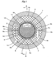
- Fig. 1 is a vertical cross-sectional view of a bearing according to the first embodiment of the present invention.
- Fig. 2 is a cross-sectional view taken along the line A-A of Fig. 1 .
- reference numeral 1 denotes a rotary shaft
- reference numeral 2 denotes the bearing.
- the bearing 2 that holds the rotary shaft 1 is divided vertically into two: a lower bearing part 2a and an upper bearing part 2b.
- the bearing 2 is composed of a bearing liner 3 and a bearing base metal 4.
- the bearing liner 3 is located on the inner circumferential side of the bearing 2 while the bearing base metal 4 is located on the outer circumferential side of the bearing 2.
- the outer circumferential surface of the bearing base metal 4 is spherical in shape as shown in Fig. 2 , and a spherical seat 15 is provided around that surface.
- the inner circumferential surface of the bearing liner 3 is lined with a bearing metal 5.
- the bearing liner 3 is also divided into two: a lower bearing liner 3a (load-receiving side) and an upper bearing liner 3b (non-load-receiving side).
- multiple cooling grooves 6 are provided around the outer circumferential surface of the lower bearing liner 3a.
- Cooling grooves 7 are also provided on the inner circumferential surface of the upper bearing liner 3b via the bearing metal 5.
- the bearing base metal 4 is also divided into two, base metals 4a and 4b, by a border 4c, and lubricant supply pockets 8a and 8b are provided in the base metals 4a and 4b, near the border.
- the lubricant supply pocket 8a communicates with the cooling grooves 6 and the cooling grooves 7.
- the lubricant supply pocket 8a also communicates with oil pockets 9a and 9b provided at the boundary of the divided bearings 2 and with a lubricant pocket 19 provided in the base metal 4a.
- the lubricant supply pocket 8a communicates, via the lubricant pocket 19, with an oil supply hole 10 provided in the spherical seat 15 located on the outer circumferential surface of the bearing base metal 4.
- the flow of the lubricant supplied from the oil supply hole 10 diverges from the oil pocket 9b.
- One is directed into the cooling grooves 7; the other is directed into the cooling grooves 6 to cool a shaft-sliding surface 16 of the bearing metal 5.
- the cooling grooves 7 on the upper side of the bearing 2 are provided on the inner circumferential surface of the bearing 2 via the upper bearing liner 3b and the bearing metal 5 and extend in the rotational direction of the rotary shaft 1.
- the terminal portions of the cooling grooves 7 communicate with an oil pocket 11 located on the upper side of the bearing 2.
- the oil pocket 11 has an oil drain hole 12.
- the oil pocket 11 communicates, through this oil drain hole 12, with a lubricant drain hole 13 provided in the upper bearing liner 3b and the upper base metal 4b.
- a lubricant drain groove 14 (shown in Fig. 2 ) is provided on the right side of the shaft-sliding surface 16, that is, on the open end side (the right side of Fig. 2 ) of a bearing housing (not shown) having the bearing therein.
- the lubricant drain groove 14 is adapted to discharge extra lubricant to the lower side of the bearing.
- Fig. 3 is a partially enlarged cross-sectional view of the bearing according to the present embodiment and explains the flow of a lubricant.
- a cooled lubricant (not shown) is supplied from the oil supply hole 10 through the lubricant pocket 19 provided in the base metal 4a into the oil pocket 9b.
- One lubricant flow from the oil pocket 9b is directed into and diverged by the cooling grooves 7 to cool the rotary shaft 1.
- the diverged lubricant flows running through the cooling grooves 7 are introduced into the oil pocket 11, where they are converged.
- the converged lubricant flow is then discharged from the oil drain hole 12 through the base metal 4 and the lubricant drain hole 13 to the outside of the bearing 2.
- the temperature-increased lubricant that has finished cooling the rotary shaft 1 does not flow onto the shaft-sliding surface 16 of the lower bearing 2a.
- the other lubricant flow from the oil pocket 9b is directed into the cooling grooves 6 to cool the shaft-sliding surface 16 from its back side (outer circumferential side) and then supplied through the oil pocket 9a (located on the opposite side of the oil pocket 9b) onto the shaft-sliding surface 16.
- Fig. 4 Described next with reference to Fig. 4 is the relationship between the distribution of the pressure exerted on an oil film (lubricant) and the temperature distribution of the film inside the journal bearing.
- Fig. 4 is a diagram showing the pressure and temperature distributions of the oil film with the use of a cross-section of the journal bearing.
- the broken line indicates the pressure distribution, and the bold line the temperature distribution.
- the oil film pressure reaches a peak just before the thickness of the film becomes minimal; the oil film temperature reaches a peak when the thickness of the film becomes minimal and decreases gradually thereafter.
- the film-minimum position inside the bearing is located 30 to 40 degrees away from the line connecting the rotational axis of the rotary shaft 1 and the lowest point of the bearing in the rotational direction of the rotary shaft 1 (the rotational direction being the counterclockwise direction of Fig. 4 ).
- the bearing temperature is the highest at that position, and so is the oil film temperature.
- journal bearing of the first embodiment is designed to supply cooled lubricant also in the reverse direction of the rotational direction of the rotary shaft 1, the bearing can be cooled with the temperature difference between the bearing and the cooled lubricant being maximal. This makes it possible to improve the cooling effect and efficiently reduce the highest temperature the bearing undergoes.
- the journal bearing is composed of the vertically divided upper and lower bearing parts and used to support the rotor of a rotary machine.
- the journal bearing structurally includes the bearing base metal and the bearing liner.
- the bearing liner is made of a material different from that of the bearing base metal.
- the bearing liner and the bearing base metal are integrated with each other by means of a fastening member.
- At least one circumferential oil groove is provided in an outer circumferential portion of the lower bearing liner, the load-receiving-side bearing liner.
- the journal bearing is provided with means for supplying a lubricant to the circumferential oil groove from the downstream side in the rotational direction of the rotor. The lubricant that has passed through the circumferential oil groove is then supplied onto the bearing load-receiving surface (rotor-sliding surface).
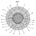
- Fig. 5 is a vertical cross-sectional view of a bearing according to a second embodiment of the present invention.
- reference numeral 1 denotes a rotary shaft
- reference numeral 2 denotes the bearing.
- the bearing 2 holding the rotary shaft 1 is vertically divided into two: the upper bearing 2b and lower bearing 2a.
- the bearing 2 is composed of the bearing liner 3 and the bearing base metal 4.
- the bearing base metal 4 is divided into the two bearing base metals 4a and 4b as also described later.
- the bearing liner 3 is located on the inner circumferential side of the bearing 2 while the bearing base metal 4 is located on the outer circumferential side of the bearing 2.
- the outer circumferential surface of the bearing base metal 4 is spherical in shape, and the spherical seat 15 is provided around that surface.
- the inner circumferential surface of the bearing liner 3 is lined with the bearing metal 5.
- the bearing liner 3 is also divided into two: the lower bearing liner 3a (load-receiving side) and the upper bearing liner 3b (non-load-receiving side).
- the multiple cooling grooves 6 are provided around the outer circumferential surface of the lower bearing liner 3a.
- the cooling grooves 7 are also provided on the inner circumferential side of the upper bearing liner 3b via the bearing metal 5.
- the bearing base metal 4 is divided into the two bearing base metals 4a and 4b.
- the lubricant supply pockets 8a and 8b are provided in the base metals 4a and 4b, in the vicinity of the boundary between the base metals 4a and 4b.
- the lubricant supply pocket 8a communicates with the cooling grooves 7; in addition, it communicates, via the oil pockets 9b provided at the boundary of the divided bearings 2, with the lubricant pocket 19 provided in the base metal 4a and with the oil supply hole 10 provided in the spherical seat 15 located on the outer circumferential side of the bearing base metal 4.
- the oil supply hole 10 has an oil supply hole 17 that communicates with the cooling grooves 6 provided in the lower bearing liner 3a.
- the cooling grooves 7 are located on the inner circumferential surface of the bearing 2 and extend in the rotational direction of the rotary shaft (rotor) 1.
- the terminal portions of the cooling grooves 7 communicate with the oil pocket 11 located on the upper side of the bearing 2.
- the oil pocket 11 has the oil drain hole 12.
- the oil pocket 11 communicates, through the oil drain hole 12, with the lubricant drain hole 13 provided in the bearing liner 3b and the base metal 4b.
- the shaft sliding surface 16 and the lower bearing liner 3a are partially removed to form a clearance 18. They are removed from where no pressure is exerted on the oil film (lubricant). As shown in Fig. 5 , the clearance 18 extends from the line located 30 to 40 degrees counterclockwise away from the line connecting the rotational axis of the rotary shaft 1 and the lowest point of the bearing 2 up to the boundary between the divided bearing parts 2a and 2b.
- a lubricant is supplied from the oil supply hole 10.
- the lubricant from the oil supply hole 10 flows into the lubricant pocket 19 and diverges therefrom into the oil supply hole 17 and the oil pocket 9b.
- the lubricant into the oil supply hole 17 flows therefrom into the cooling grooves 6 to cool the shaft-sliding surface 16 from its back side (outer circumferential side) and then supplied through the oil pocket 9a onto the shaft-sliding surface 16.
- the lubricant into the oil pocket 9b is directed into and diverged by the cooling grooves 7 to cool the rotary shaft 1.
- the diverged lubricant flows running through the cooling grooves 7 are introduced into the oil pocket 11, where they are converged.
- the converged lubricant flow is then discharged from the oil drain hole 12 through the base metal 4 and the lubricant drain hole 13 to the outside of the bearing 2.
- the temperature-increased lubricant that has finished cooling the rotary shaft 1 does not flow onto the shaft-sliding surface 16 of the lower bearing 2a.
- the present embodiment can reduce the damage to that portion, i.e., the clearance 18 due to lack of lubricant.
- the present embodiment is also most effective in cooling the journal bearing because the lubricant first cools the maximum temperature portion of the bearing.
- the journal bearing is composed of the vertically divided upper and lower bearing parts and used to support the rotor of a rotary machine.
- the journal bearing structurally includes the bearing base metal and the bearing liner.
- the bearing liner is made of a material different from that of the bearing base metal.
- the bearing liner and the bearing base metal are integrated with each other by means of a fastening member.
- the lower bearing liner on the load-receiving side has the shaft-sliding surface that extends counterclockwise from the left boundary in Fig. 5 between the upper and lower bearing parts up to the area in which no pressure is exerted on the lubricant film.
- At least one circumferential oil groove is provided in an outer circumferential portion of the lower bearing liner, the load-receiving-side bearing liner.
- the journal bearing is provided with means for supplying a lubricant to the circumferential oil groove from the downstream side in the rotational direction of the rotor.
- the lubricant that has passed through the circumferential oil groove is then supplied onto the bearing load-receiving surface (rotor-sliding surface).
- Fig. 6 is a vertical cross-sectional view of a bearing according to a third embodiment of the present invention.
- Fig. 7 is a vertical cross-sectional view of a part of the bearing shown in Fig. 6 .
- reference numeral 1 denotes a rotary shaft
- reference numeral 2 denotes the bearing.
- the bearing 2 holding the rotary shaft 1 is vertically divided into two: the upper bearing 2b and lower bearing 2a.
- the bearing 2 is composed of the bearing liner 3 and the bearing base metal 4.
- the bearing base metal 4 is divided into the two bearing base metals 4a and 4b as also described later.
- the bearing liner 3 is located on the inner circumferential side of the bearing 2 while the bearing base metal 4 is located on the outer circumferential side of the bearing 2.
- the outer circumferential surface of the bearing base metal 4 is spherical in shape, and the spherical seat 15 is provided around that surface.
- the inner circumferential surface of the bearing liner 3 is lined with the bearing metal 5.
- the bearing liner 3 is also divided into two: the lower bearing liner 3a (load-receiving side) and the upper bearing liner 3b (non-load-receiving side).
- the multiple cooling grooves 6 are provided around the outer circumferential surface of the lower bearing liner 3a.
- Each of the bearing liners 3a and 3b is a partial bearing extending approximately 100 degrees around the rotary shaft 1.
- the bearing liners 3a and 3b has the oil supply pockets 8a and 8b at inlets thereof, respectively.
- the oil supply pocket 8a communicates with the cooling grooves 6.
- the cooling grooves 6 communicate with the lubricant pocket 19 provided in the bearing base metal 4a.
- the oil supply pocket 8b communicates with the oil pocket 9b provided in the bearing base metal 4b.
- the oil supply pocket 8b and the oil pocket 9b merge at the oil pocket 19.
- the oil pocket 19 communicates with the supply oil hole 10.
- the present embodiment is especially effective for an elliptical bearing, in which kinetic pressure is also exerted on its upper bearing portion, non-load-receiving bearing; it is also applicable to a circular bearing.
- a lubricant is supplied from the oil supply hole 10 into the lubricant pocket 19, from which the lubricant diverges into the oil supply hole 17 and the oil pocket 9b.
- the lubricant into the oil supply hole 17 flows therefrom into the cooling grooves 6 to cool the shaft-sliding surface 16 from its back side (outer circumferential side) and then supplied through the oil supply pocket 8a onto the shaft-sliding surface 16.
- the lubricant into the oil pocket 9b lubricates the shaft-sliding surface of the upper bearing 2b and is then discharged to the outside of the bearing from a cut out portion 18b provided on both sides of the bearing and downstream in the lubricant flowing direction.
- the temperature-increased lubricant that has lubricated the shaft-sliding surface of the upper bearing 2b does not flow into the shaft-sliding surface of the lower bearing 2a.
- the journal bearing is composed of the vertically divided upper and lower bearing parts and used to support the rotor of a rotary machine.
- the journal bearing structurally includes the bearing base metal and the bearing liner.
- the bearing liner is made of a material different from that of the bearing base metal.
- the bearing liner and the bearing base metal are integrated with each other by means of a fastening member.
- the lower bearing liner on the load-receiving side and the upper bearing liner on the non-load-receiving side each have a shaft-sliding surface that extends to cover the area in which pressure is exerted on the lubricant film.
- At least one circumferential oil groove is provided in an outer circumferential portion of the lower bearing liner, the load-receiving-side bearing liner.
- the journal bearing is provided with means for supplying a lubricant to the circumferential oil groove from the downstream side in the rotational direction of the rotor.
- the lubricant that has passed through the circumferential oil groove is then supplied onto the bearing load-receiving surface (rotor-sliding surface).
- a bearing according to a fourth embodiment of the present invention is described below with reference to Figs. 8 to 13B .
- Fig. 8 is a vertical cross-sectional view of a bearing of the journal bearing device according to the present embodiment.
- Figs. 9 and 10 are perspective views of a lower bearing 102a.
- a bearing 102 that supports a rotary shaft 101 structurally includes a bearing base metal 104 and a bearing liner 103 disposed on the inner circumferential side of the bearing base metal 104, both not shown in Figs. 8 and 9 .
- the inner circumferential surface of the bearing liner 103 is lined with a bearing metal (not shown).
- the bearing metal constitutes a shaft-sliding surface 127 that faces the rotary shaft 101.
- the outer circumferential surface of the bearing base metal 104 is provided with a spherical seat (not shown).
- the bearing 102 is vertically divided into two bearings, an upper bearing 102b and a lower bearing 102a, by a border 135. That is, the bearing base metal 104 is also vertically divided into two bearing base metals, an upper base metal 104b and a lower base metal 104a, by the border 135; in addition, the bearing base metal 104 is also vertically divided into two bearing liners, an upper bearing liner 103b and a lower bearing liner 103a.
- the lower bearing 102a is composed of the bearing base metal 104a and the bearing liner 103a located on the inner circumferential side of the bearing base metal 104a. At least one circumferential cooling groove 106 is provided on the outer circumferential surface of the bearing liner 103a.
- the lower bearing base metal 104a has a contact surface 129a that comes into contact with the upper bearing base metal 104b.
- the contact surface 129a is provided with an oil supply path 107.
- the oil supply path 107 communicates with an oil supply hole (not shown) provided in the spherical seat and with the inner circumferential side of the bearing base metal 104.
- the oil supply hole is connected with an oil supply pump (not shown) provided outside the bearing 102. A lubricant supplied from the oil supply pump thus flows through the oil supply hole and the oil supply path 107 into the inner circumferential side of the bearing base metal 104.
- the oil supply path 107 is formed by coupling the contact surface 129a of the bearing base metal 104a on which the groove (the oil supply path 107) is provided to a contact surface (not shown) of the bearing base metal 104b that faces the bearing base metal 104a.
- the lower bearing liner 103a has also contact surfaces 130a and 130b.
- the contact surfaces 130a and 130b are joined to a contact surface of the upper bearing liner 130b.
- the contact surface 130a has a lubricant introduction path 108a thereon; the contact surface 130b has a lubricant introduction path 108b thereon.
- the lubricant introduction paths 108a and 108b leads to a shaft-sliding surface 127a provided on the inner circumferential surface of the lower bearing liner 103a.
- the lubricant introduction paths 108a and 108b are formed by joining the contact surfaces 130a and 130b onto the contact surface of the upper bearing liner 103b, which faces the contact surfaces 130a and 130b.
- the lubricant introduction path 108b communicates with cooling grooves 106.
- the cooling grooves 106 communicate with the lubricant introduction path 108a.
- the lubricant introduction path 108a communicates also with the oil supply path 107.
- the lubricant supplied from the outside of the bearing 102 by the oil supply pump thus flows through the oil supply hole and oil supply path 107 into the lubricant introduction path 108a.
- a part of the lubricant flows into the cooling grooves 106 that communicate with the lubricant introduction path 108a to cool the shaft-sliding surface 127a of the lower bearing 102a from its back side (the outer circumferential side).
- the part of the lubricant then flows through the lubricant introduction path 108b onto the shaft-sliding surface 127.
- the oil supply path 107 is provided on the contact surface 129a, not the contact surface 129b, so that the lubricant flows through the cooling grooves 106 in the opposite direction of the rotational direction of the rotary shaft 1.
- circumferential cooling grooves are provided on the inner circumferential surface of the bearing metal of the upper bearing liner 103b, and the starting portions of the cooling grooves from which the grooves extend communicate with the lubricant introduction path 108a.
- the other ends (terminal portions) of the cooling grooves communicate with an oil pocket (not shown) provided in the upper bearing 102b.
- the oil pocket has an oil drain hole (not shown). The oil pocket communicates through the oil drain hole with a lubricant drain hole (not shown) provided in the bearing liner 103b and the base metal 104b.
- a lubricant drain groove (not shown) is provided close to the edge of the shaft-sliding surface on the open end side of a bearing housing (not shown) having the bearing therein.
- the lubricant drain groove is adapted to discharge extra lubricant to the lower side of the bearing.
- the cooling grooves 106 have turbulence inducing structures 114 at one or more locations.
- the turbulence inducing structures 114 are designed to disturb the flow of the lubricant flowing through the cooling grooves 106.
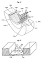
- Fig. 11 shows an example of the turbulence inducing structures 114.
- the turbulence inducing structure 114 shown in Fig. 11 has a shaft-sliding surface side inner wall 115 and side walls 116, which constitute one of the cooling grooves 106.
- a plurality of projecting turbulence-inducing bodies 117a are provided on the shaft-sliding surface side inner wall 115 and arranged parallel to the longitudinal direction of the rotary shaft 101.
- Fig. 12 shows another example of the turbulence inducing structures.
- the structure of Fig. 12 has a cylindrical turbulence inducing body 117b provided between the side walls 116 of the cooling groove 106 so as to connect them.
- Fig. 18 shows the temperature distribution of the lubricant film present on the shaft-sliding surface 127. Similar to the first embodiment, when the rotary shaft 101 rotates, the lubricant film temperature becomes highest at the position located 30 to 40 degrees away from the broken line connecting the rotational axis 133 of the rotary shaft 101 and the lowest point of the lower bearing 102a in the rotational direction of the rotary shaft 101 (the rotational direction being the counterclockwise direction of Fig. 18 and indicated by the uncolored arrow). The bearing temperature is also highest at that position and thereabout.
- the lubricant flows through the cooling grooves 106 in the reverse direction of the rotational direction of the rotary shaft 101.
- the lubricant passes through the highest temperature portion of the bearing when it flows from the lubricant introduction path 108a through the cooling grooves 106 to the lubricant introduction path 108b.
- the turbulence inducing structures 114 are thus provided upstream of the bearing highest temperature portion in the flow direction of the lubricant inside the cooling grooves 106; alternatively, they are provided at the position located 30 degrees or more away from the broken line connecting the rotational axis 133 and the lowest point of the lower bearing 102a in the rotational direction of the rotary shaft 101.
- the flow of the lubricant from the lubricant introduction path 108a into the cooling grooves 106 is thus disturbed by the turbulence inducing structures 114 before it reaches the bearing highest temperature portion to cool that portion. Thereafter, the lubricant flows through the lubricant introduction path 108b onto the shaft-sliding surface 127. Since the lubricant flow is disturbed upstream of the bearing highest temperature portion, this improves the efficiency of the heat transfer performed by means of the lubricant. A higher cooling effect can be obtained than in the bearing of the first embodiment.
- the turbulence inducing structures 114 may be installed also at the bearing highest temperature portions inside the cooling grooves. This produces a still higher cooling effect because the turbulence inducing body 117 increases the surface area of the turbulence inducing structure 114.
- Fig. 10 is a perspective view of the lower bearing 102a.
- the bearing 102a is divided into the bearing liner 103a and the bearing base metal 104a.
- At least one of the circumferential cooling grooves 106 is provided on the outer circumferential surface of the bearing liner 103a.
- the cooling groove 106 has a slit-shaped, installation groove 118.
- the turbulence inducing body 117 is included in a structure 119 as shown in Figs. 13A and 13B .
- the structure 119 having the turbulence inducing body 117 is inserted in and engaged with the mounting structure 118, and whereby the turbulence inducing body 117 is installed in the cooling groove (also called an oil passing hole) 106 to form the turbulence inducing structure 114.
- Figs. 13A and 13B shows detail examples of the structure 119.
- Each of structures 119a and 119b shown in Figs. 13A and 13B has side wall portions 120 and an inner wall portion 121.
- the side wall portions 120 of each of the structures 119a and 119b are inserted in installation groove 118 formed into the side walls 116.
- the inner wall portion 121 of each of the structures 119a and 119b are inserted in installation groove 118 formed into the shaft-sliding surface side inner wall 115.
- the structure 119a has a turbulence inducing body 117a on the inner wall portion 121 present on the side of the cooling groove 106.
- the turbulence inducing body 117a is composed of a plurality of protrusions.
- each of the protrusions is not limited to the shape shown in Fig. 13A and may be cylindrical.
- the structure 119b has a turbulence inducing body 117b.
- the turbulence inducing body 117b is provided between the side wall portions 120 and connects the side wall portions 120.
- the turbulence inducing body 117b has a cylindrical shape.
- the structure 119 is made of a material having a higher heat transfer property than that of the bearing liner 103.
- the material of the structure 119 is aluminum, copper, chromium copper (that is a copper alloy), or the like. This improves the efficiency of the heat transfer between the lubricant (serving as a cooling medium) and the bearing liner and contributes to an improvement of cooling performance.
- An arrow shown in Fig. 8 indicates the direction of the flow of the lubricant.
- the lubricant supplied from the outside of the bearing by the oil supply pump passes through the oil supply hole 131 and the oil supply path 107. Then, the lubricant passes through the lubricant introduction path 108a and is supplied to the shaft-sliding surface 127a. The other part of the lubricant passes through the oil supply path 107 and the lubricant introduction path 108a and flows into the cooling groove 106 to ensure that the flow of the other part of the lubricant is disturbed by the turbulence inducing structure 114.
- a lubricant has high viscosity and a low heat transfer property. Therefore, the flow of the lubricant in the cooling groove 106 easily becomes laminar. In order to improve the cooling effect, it is effective to disturb the flow of the lubricant. Since the lubricant passes through the turbulence inducing structure 114, the turbulence inducing body 117 disturbs the flow of the lubricant to improve the efficiency of the heat transfer. The lubricant that passes through the cooling groove 106 and is used to cool the area in which the temperature of the bearing is the highest increases in temperature. Therefore, viscosity of the lubricant is reduced. In addition, the lubricant is introduced onto the shaft-sliding surface 127 from the lubricant introduction path 108b. This can reduce damage caused by a friction.
- a turbulence inducing body 117a is provided on the shaft-sliding surface side inner wall 115 of the cooling groove 106 and projects from the shaft-sliding surface side inner wall 115.
- the turbulence inducing body 117a disturbs the flow of the lubricant flowing near the surface (located on the side of the shaft-sliding surface) of the cooling groove 106 to improve the efficiency of the heat transfer.
- Fig. 11 a turbulence inducing body 117a is provided on the shaft-sliding surface side inner wall 115 of the cooling groove 106 and projects from the shaft-sliding surface side inner wall 115.
- the turbulence inducing body 117a disturbs the flow of the lubricant flowing near the surface (located on the side of the shaft-sliding surface) of the cooling groove 106 to improve the efficiency of the heat transfer.
- a turbulence inducing body 117b is provided between the side walls of the cooling groove 106 and near the surface (located on the side of the shaft-sliding surface) of the cooling groove 106.
- the turbulence inducing body 117b has a cylindrical shape. The turbulence inducing body 117b causes a swirl in the flow of the lubricant to improve the efficiency of the heat transfer.
- the position of the area in which the temperature of the oil film is the highest is near a location at which the maximum load is applied from the rotary shaft. According to the present invention, this load causes the bearing surface located above the cooling groove 106 to be transformed, and thereby causes the lubricant to be dammed on the bearing surface. This improves lubrication performance.
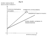
- Fig. 14 is a graph showing temperature characteristics of the journal bearing according to the present embodiment.
- a broken line shown in Fig. 14 indicates the relationship between the highest temperature of a shaft-sliding surface of a conventional bearing and a rotation speed of the conventional bearing. As the rotation speed increases, the temperature of the bearing shaft-sliding surface increases.
- a solid line shown in Fig. 14 indicates the temperature characteristics of the journal bearing according to the present embodiment. Since the journal bearing according to the present embodiment includes the lower bearing liner 103a having the cooling groove 106, the lubricant flows in the area in which the temperature of the oil film is the highest of all portions of the oil film.
- the increase rate of the temperature of the shaft-sliding surface of the journal bearing according to the present embodiment is lower than that of the temperature of the shaft-sliding surface of the conventional bearing.
- the journal bearing according to the present embodiment can be used at a rotation speed at which the conventional bearing burns out and cannot be used. This makes it possible to increase an operation speed of a rotary machine such as a steam turbine, a gas turbine and a centrifugal compressor and increase a load applied to such a rotary machine.
- Fig. 15 is a vertical cross-sectional view of a bearing according to a fifth embodiment of the present invention.
- an inner circumferential side portion of the oil supply path 107 provided in the bearing base metal 104a only communicates with the cooling groove 106.
- the upper bearing liner 103b has a cooling groove 132 formed in an outer circumferential surface thereof.
- the cooling groove 132 extends along a circumferential direction of the upper bearing liner 103b.
- the cooling groove 132 is designed to communicate with the lubricant introduction path 108b of the lower bearing liner 103a when the upper bearing 102a and the lower bearing 102a are integrated with each other by means of a fastening member.
- a lubricant introduction hole 134 is provided near the contact surface 130a of the lower bearing liner 103a and the contact surface (not shown) of the upper bearing liner 103b.
- the contact surface 130a and the contact surface face each other.
- the lubricant introduction hole 134 communicates with a shaft-sliding surface 127b of the upper bearing 102b and the cooling groove 132.
- the shaft-sliding surface 127b is located on the inner circumferential side of the bearing liner.
- the lubricant supplied from the outside of the bearing 102 by the oil supply pump passes through the oil supply hole 131 and the oil supply path 107. Then, all parts of the lubricant flow into the cooling groove 106.
- the lubricant that flows into the cooling groove 106 cools the lower bearing 102a. After that, a part of the lubricant flows onto the shaft-sliding surface 127a through the lubricant introduction path 108b.
- the remaining part of the lubricant flows into the cooling groove 132 that communicates with the lubricant introduction path 108b.
- the remaining part of the lubricant flows to the shaft-sliding surface 127b of the upper bearing 102b through the lubricant introduction hole 134 that communicates with the cooling groove 132.
- the cooling groove 106 has the turbulence inducing structure 114 in the same manner as that in the fourth embodiment.
- the turbulence inducing structure 114 is provided on the upstream side of the flow of the lubricant present in the cooling groove 106 with respect to the area in which the temperature of the bearing is the highest of all portions of the bearing.
- the turbulence inducing structure 114 is located on the side of the lower bearing 102a and on the vertical axis (connecting the rotational axis 133 of the rotor with the bottom point of the bearing 102a) rotated by 30 degrees or more in the rotational direction of the rotor.
- An arrow shown in Fig. 15 indicates the direction of the flow of the lubricant.
- the lubricant is supplied from the outside of the bearing and passes through the oil supply hole 131. Then, the lubricant is supplied to the oil supply path 107. All parts of the lubricant pass through the cooling groove 106 to cool the lower bearing 102.
- the cooling groove 106 has one or more of the turbulence inducing structures 114 at one or more locations in the same manner as that in the fourth embodiment.
- the turbulence inducing body 117 disturbs the flow of the lubricant to improve the efficiency of the heat transfer performed by means of the lubricant.
- the bearing since the bearing is configured to ensure that all the parts of the lubricant supplied from the oil supply path 107 are supplied to the cooling groove 106, the flow rate of the lubricant is higher than that in the fourth embodiment.
- the increase rate of the temperature of the shaft-sliding surface of the journal bearing according to the present embodiment is lower than that of the temperature of the shaft-sliding surface of the conventional bearing.
- the journal bearing according to the present embodiment can be used at a rotation speed at which the conventional bearing burns out and cannot be used. This makes it possible to increase an operation speed of a rotary machine such as a steam turbine, a gas turbine and a centrifugal compressor and increase a load applied to such a rotary machine.
- Figs. 16A and 16B show examples in which the journal bearing according to the present invention is applied to a steam turbine used as an example of a rotary machine.
- a single shaft steam turbine including a high pressure turbine 122 and a lower pressure turbine 123 typically has a high pressure turbine rotor 124 and a lower pressure turbine rotor 125. These rotors and a generator are coupled to each other by means of a single shaft. In order to improve an efficiency of heat transfer in the steam turbine, a blade of each rotor is made longer. This results in an increase in the diameter of a shaft. Thus, the weight of the steam turbine increases.
- Such a steam turbine as that shown in Fig. 16A has two bearings 25 holding the rotors.
- journal bearing according to the present invention can bear a high load compared with conventional techniques.
- the single journal bearing according to the present invention can be provided between the rotors as shown in Fig. 16B . This reduces the total length of the turbine and the size of a building for construction of the turbine. In addition, since it is possible to reduce the number of the bearings, the turbine can be easily maintained compared with the conventional techniques.
Landscapes
- Engineering & Computer Science (AREA)
- General Engineering & Computer Science (AREA)
- Mechanical Engineering (AREA)
- Chemical & Material Sciences (AREA)
- Oil, Petroleum & Natural Gas (AREA)
- Sliding-Contact Bearings (AREA)
- Mounting Of Bearings Or Others (AREA)
Abstract
Description
- The present invention relates to a structure of a bearing that holds a rotary body. The invention more particularly relates to a journal bearing that prevents seizure and holds a rotary body with a high load, and to a lubricant supply structure of the journal bearing, which is designed to supply a cooled lubricant to a back surface of the bearing and reduce the temperature of the bearing.
- An elliptical bearing has been generally used to prevent a self-excited oscillation as a bearing holding a large rotary body (e.g. for a thermal power plant) in which a natural frequency of a multi-span shaft is relatively low.
- Since a primary critical speed of a bearing for steam turbine having a large capacity, like a conventional steam turbine shown in
Fig. 17 , is low, an oil groove is provided at a central portion of alower bearing 2a in the direction of the width of thelower bearing 2a and extends along a circumferential direction of thelower bearing 2a to reduce load capacity of a bearing, increase an eccentricity ratio, and ensure stability. Because a rim speed of such a large-scaled bearing is approximately 100 m/s, flow of a lubricant is turbulent, and apparent viscosity of the lubricant increases. Thus the temperature of the bearing tends to increase. Therefore, a cooling groove is provided in an upper half bearing 2b. The cooling groove is designed to cool the rotary shaft, and it is therefore difficult to cool the highest-temperature portion of the bearing. -
JP-A-H08-93769 JP-A-H08-93769 -
JP-A-H10-213130 JP-A-2006-138353 JP-A-2004-92878 - As disclosed in
JP-A-H08-93769 - As disclosed in
JP-A-10-213130 JP-A-2006-138353 - As disclosed in
JP-A-2004-92878 - An object of the present invention is to provide a journal bearing device capable of cooling a bearing and reducing damage of the bearing by supplying a cooled lubricant to an outer circumference of the bearing located on a load-receiving side to cool the bearing and supplying the lubricant to a shaft-sliding surface of the bearing.
- To accomplish the aforementioned object, the journal bearing device has a bearing base metal and a bearing liner. The bearing base metal and the bearing liner constitute a bearing. The bearing liner is provided on an inner circumferential side of the bearing base metal. The bearing liner is divided into an upper bearing liner and a lower bearing liner. The lower bearing liner has a cooling groove formed in an outer circumferential surface thereof. The cooling groove extends along a circumferential direction of the lower bearing liner. A lubricant is supplied to the cooling groove such that the lubricant flows in the opposite direction to a rotational direction of a rotor. The lubricant passes through the cooling groove and is supplied to a bearing load-receiving surface of the bearing. The journal bearing device is realized with a configuration described in each claim of this application.
- The journal bearing device according to the present invention is capable of efficiently cooling an area in which the temperature of a portion of the bearing is the highest of all portions of the bearing, preventing the bearing from burning and being damaged, allowing high pressure to be applied to the surface of the bearing, and reducing damage of the bearing and the amount of a lubricant to be supplied, since the lubricant is supplied to the outer circumferential surface of the bearing liner such that the lubricant flows in the opposite direction to the rotational direction of the rotor.
-
-
Fig. 1 is a vertical cross-sectional view of a bearing according to a first embodiment of the present invention. -
Fig. 2 is a vertical cross-sectional view of a part of the bearing shown inFig. 1 . -
Fig. 3 is a diagram showing a part of the bearing and explaining the state in which a lubricant is supplied. -
Fig. 4 is a diagram showing a distribution of pressure of an oil film and a distribution of the temperature of the oil film. -
Fig. 5 is a vertical cross-sectional view of a bearing according to a second embodiment of the present invention. -
Fig. 6 is a vertical cross-sectional view of a bearing according to a third embodiment of the present invention. -
Fig. 7 is a vertical cross-sectional view of a part of the bearing shown inFig. 6 . -
Fig. 8 is a vertical cross-sectional view of a bearing according to a fourth embodiment of the present invention. -
Fig. 9 is a perspective view of a lower bearing of the bearing shown inFig. 8 . -
Fig. 10 is a perspective view of the lower bearing and shows an example of installment of a structure designed to disturb flow of a lubricant. -
Fig. 11 is a diagram showing an example of a turbulence inducing body designed to disturb the flow of the lubricant. -
Fig. 12 is a diagram showing another example of the turbulence inducing body designed to disturb the flow of the lubricant. -
Figs. 13A and 13B are diagrams each showing a structure designed to disturb the flow of the lubricant present in an oil passing hole according to the present invention. -
Fig. 14 is a graph showing the relationship between the highest temperature of a bearing shaft-sliding surface and a rotation speed of a rotary machine and shows an advantage obtained when the bearing according to the present invention is used under the condition that the rotation speed of the rotary machine is high. -
Fig. 15 is a vertical cross-sectional view of a bearing according to a fifth embodiment of the present invention. -
Figs. 16A and 16B are diagrams each showing a rotary machine using the bearing according to the present invention. -
Fig. 17 is a vertical cross-sectional view of a conventional bearing structure. -
Fig. 18 is a diagram showing a distribution of the temperature of an oil film and the positional relationship between the oil film and the bearing. - A first embodiment of the present invention is described below with reference to the accompanying drawings. First Embodiment
-
Fig. 1 is a vertical cross-sectional view of a bearing according to the first embodiment of the present invention. -
Fig. 2 is a cross-sectional view taken along the line A-A ofFig. 1 . - With cross-reference to
Figs. 1 and2 ,reference numeral 1 denotes a rotary shaft, andreference numeral 2 denotes the bearing. Thebearing 2 that holds therotary shaft 1 is divided vertically into two: alower bearing part 2a and anupper bearing part 2b. Thebearing 2 is composed of abearing liner 3 and abearing base metal 4. As shown inFig. 1 , thebearing liner 3 is located on the inner circumferential side of thebearing 2 while the bearingbase metal 4 is located on the outer circumferential side of thebearing 2. The outer circumferential surface of the bearingbase metal 4 is spherical in shape as shown inFig. 2 , and aspherical seat 15 is provided around that surface. The inner circumferential surface of thebearing liner 3 is lined with a bearingmetal 5. Thebearing liner 3 is also divided into two: alower bearing liner 3a (load-receiving side) and anupper bearing liner 3b (non-load-receiving side). As shown inFig.2 ,multiple cooling grooves 6 are provided around the outer circumferential surface of thelower bearing liner 3a. Coolinggrooves 7 are also provided on the inner circumferential surface of theupper bearing liner 3b via the bearingmetal 5. - The bearing
base metal 4 is also divided into two,base metals border 4c, andlubricant supply pockets base metals lubricant supply pocket 8a communicates with thecooling grooves 6 and thecooling grooves 7. Thelubricant supply pocket 8a also communicates withoil pockets bearings 2 and with alubricant pocket 19 provided in thebase metal 4a. Furthermore, thelubricant supply pocket 8a communicates, via thelubricant pocket 19, with anoil supply hole 10 provided in thespherical seat 15 located on the outer circumferential surface of the bearingbase metal 4. The flow of the lubricant supplied from theoil supply hole 10 diverges from theoil pocket 9b. One is directed into thecooling grooves 7; the other is directed into thecooling grooves 6 to cool a shaft-slidingsurface 16 of the bearingmetal 5. - The
cooling grooves 7 on the upper side of thebearing 2 are provided on the inner circumferential surface of thebearing 2 via theupper bearing liner 3b and the bearingmetal 5 and extend in the rotational direction of therotary shaft 1. The terminal portions of thecooling grooves 7 communicate with anoil pocket 11 located on the upper side of thebearing 2. Theoil pocket 11 has anoil drain hole 12. Theoil pocket 11 communicates, through thisoil drain hole 12, with alubricant drain hole 13 provided in theupper bearing liner 3b and theupper base metal 4b. For the purpose of preventing lubricant leakage, a lubricant drain groove 14 (shown inFig. 2 ) is provided on the right side of the shaft-slidingsurface 16, that is, on the open end side (the right side ofFig. 2 ) of a bearing housing (not shown) having the bearing therein. Thelubricant drain groove 14 is adapted to discharge extra lubricant to the lower side of the bearing. - Next, an effect of the present embodiment is described below with reference to
Fig. 3 . -
Fig. 3 is a partially enlarged cross-sectional view of the bearing according to the present embodiment and explains the flow of a lubricant. - In
Fig. 3 , a cooled lubricant (not shown) is supplied from theoil supply hole 10 through thelubricant pocket 19 provided in thebase metal 4a into theoil pocket 9b. One lubricant flow from theoil pocket 9b is directed into and diverged by the coolinggrooves 7 to cool therotary shaft 1. The diverged lubricant flows running through thecooling grooves 7 are introduced into theoil pocket 11, where they are converged. The converged lubricant flow is then discharged from theoil drain hole 12 through thebase metal 4 and thelubricant drain hole 13 to the outside of thebearing 2. - Thus, the temperature-increased lubricant that has finished cooling the
rotary shaft 1 does not flow onto the shaft-slidingsurface 16 of thelower bearing 2a. On the other hand, the other lubricant flow from theoil pocket 9b is directed into thecooling grooves 6 to cool the shaft-slidingsurface 16 from its back side (outer circumferential side) and then supplied through theoil pocket 9a (located on the opposite side of theoil pocket 9b) onto the shaft-slidingsurface 16. - Described next with reference to
Fig. 4 is the relationship between the distribution of the pressure exerted on an oil film (lubricant) and the temperature distribution of the film inside the journal bearing. -
Fig. 4 is a diagram showing the pressure and temperature distributions of the oil film with the use of a cross-section of the journal bearing. - In
Fig. 4 , the broken line indicates the pressure distribution, and the bold line the temperature distribution. The oil film pressure reaches a peak just before the thickness of the film becomes minimal; the oil film temperature reaches a peak when the thickness of the film becomes minimal and decreases gradually thereafter. The film-minimum position inside the bearing is located 30 to 40 degrees away from the line connecting the rotational axis of therotary shaft 1 and the lowest point of the bearing in the rotational direction of the rotary shaft 1 (the rotational direction being the counterclockwise direction ofFig. 4 ). The bearing temperature is the highest at that position, and so is the oil film temperature. Because the journal bearing of the first embodiment is designed to supply cooled lubricant also in the reverse direction of the rotational direction of therotary shaft 1, the bearing can be cooled with the temperature difference between the bearing and the cooled lubricant being maximal. This makes it possible to improve the cooling effect and efficiently reduce the highest temperature the bearing undergoes. - The features of the journal bearing according to the present embodiment can be roughly summarized as follows. The journal bearing is composed of the vertically divided upper and lower bearing parts and used to support the rotor of a rotary machine. The journal bearing structurally includes the bearing base metal and the bearing liner. The bearing liner is made of a material different from that of the bearing base metal. The bearing liner and the bearing base metal are integrated with each other by means of a fastening member. At least one circumferential oil groove is provided in an outer circumferential portion of the lower bearing liner, the load-receiving-side bearing liner. The journal bearing is provided with means for supplying a lubricant to the circumferential oil groove from the downstream side in the rotational direction of the rotor. The lubricant that has passed through the circumferential oil groove is then supplied onto the bearing load-receiving surface (rotor-sliding surface).
-
Fig. 5 is a vertical cross-sectional view of a bearing according to a second embodiment of the present invention. - In
Fig. 5 ,reference numeral 1 denotes a rotary shaft, andreference numeral 2 denotes the bearing. Thebearing 2 holding therotary shaft 1 is vertically divided into two: theupper bearing 2b andlower bearing 2a. Thebearing 2 is composed of thebearing liner 3 and the bearingbase metal 4. The bearingbase metal 4 is divided into the twobearing base metals bearing liner 3 is located on the inner circumferential side of thebearing 2 while the bearingbase metal 4 is located on the outer circumferential side of thebearing 2. The outer circumferential surface of the bearingbase metal 4 is spherical in shape, and thespherical seat 15 is provided around that surface. The inner circumferential surface of thebearing liner 3 is lined with the bearingmetal 5. Thebearing liner 3 is also divided into two: thelower bearing liner 3a (load-receiving side) and theupper bearing liner 3b (non-load-receiving side). Themultiple cooling grooves 6 are provided around the outer circumferential surface of thelower bearing liner 3a. Thecooling grooves 7 are also provided on the inner circumferential side of theupper bearing liner 3b via the bearingmetal 5. - The bearing
base metal 4 is divided into the twobearing base metals lubricant supply pockets base metals base metals lubricant supply pocket 8a communicates with thecooling grooves 7; in addition, it communicates, via theoil pockets 9b provided at the boundary of the dividedbearings 2, with thelubricant pocket 19 provided in thebase metal 4a and with theoil supply hole 10 provided in thespherical seat 15 located on the outer circumferential side of the bearingbase metal 4. Theoil supply hole 10 has anoil supply hole 17 that communicates with thecooling grooves 6 provided in thelower bearing liner 3a. - The
cooling grooves 7 are located on the inner circumferential surface of thebearing 2 and extend in the rotational direction of the rotary shaft (rotor) 1. The terminal portions of thecooling grooves 7 communicate with theoil pocket 11 located on the upper side of thebearing 2. Theoil pocket 11 has theoil drain hole 12. Theoil pocket 11 communicates, through theoil drain hole 12, with thelubricant drain hole 13 provided in thebearing liner 3b and thebase metal 4b. - The
shaft sliding surface 16 and thelower bearing liner 3a are partially removed to form aclearance 18. They are removed from where no pressure is exerted on the oil film (lubricant). As shown inFig. 5 , theclearance 18 extends from the line located 30 to 40 degrees counterclockwise away from the line connecting the rotational axis of therotary shaft 1 and the lowest point of thebearing 2 up to the boundary between the divided bearingparts - In the present embodiment, a lubricant is supplied from the
oil supply hole 10. The lubricant from theoil supply hole 10 flows into thelubricant pocket 19 and diverges therefrom into theoil supply hole 17 and theoil pocket 9b. The lubricant into theoil supply hole 17 flows therefrom into thecooling grooves 6 to cool the shaft-slidingsurface 16 from its back side (outer circumferential side) and then supplied through theoil pocket 9a onto the shaft-slidingsurface 16. The lubricant into theoil pocket 9b, on the other hand, is directed into and diverged by the coolinggrooves 7 to cool therotary shaft 1. The diverged lubricant flows running through thecooling grooves 7 are introduced into theoil pocket 11, where they are converged. The converged lubricant flow is then discharged from theoil drain hole 12 through thebase metal 4 and thelubricant drain hole 13 to the outside of thebearing 2. Thus, the temperature-increased lubricant that has finished cooling therotary shaft 1 does not flow onto the shaft-slidingsurface 16 of thelower bearing 2a. - Because the
shaft sliding surface 16 and thelower bearing liner 3a are removed where no pressure is exerted on the lubricant film, the present embodiment can reduce the damage to that portion, i.e., theclearance 18 due to lack of lubricant. The present embodiment is also most effective in cooling the journal bearing because the lubricant first cools the maximum temperature portion of the bearing. - The features of the journal bearing according to the second embodiment can be roughly summarized as follows. The journal bearing is composed of the vertically divided upper and lower bearing parts and used to support the rotor of a rotary machine. The journal bearing structurally includes the bearing base metal and the bearing liner. The bearing liner is made of a material different from that of the bearing base metal. The bearing liner and the bearing base metal are integrated with each other by means of a fastening member. The lower bearing liner on the load-receiving side has the shaft-sliding surface that extends counterclockwise from the left boundary in
Fig. 5 between the upper and lower bearing parts up to the area in which no pressure is exerted on the lubricant film. At least one circumferential oil groove is provided in an outer circumferential portion of the lower bearing liner, the load-receiving-side bearing liner. The journal bearing is provided with means for supplying a lubricant to the circumferential oil groove from the downstream side in the rotational direction of the rotor. The lubricant that has passed through the circumferential oil groove is then supplied onto the bearing load-receiving surface (rotor-sliding surface). -
Fig. 6 is a vertical cross-sectional view of a bearing according to a third embodiment of the present invention. -
Fig. 7 is a vertical cross-sectional view of a part of the bearing shown inFig. 6 . - With cross-reference to
Fig. 6 and7 ,reference numeral 1 denotes a rotary shaft, andreference numeral 2 denotes the bearing. Thebearing 2 holding therotary shaft 1 is vertically divided into two: theupper bearing 2b andlower bearing 2a. Thebearing 2 is composed of thebearing liner 3 and the bearingbase metal 4. The bearingbase metal 4 is divided into the twobearing base metals bearing liner 3 is located on the inner circumferential side of thebearing 2 while the bearingbase metal 4 is located on the outer circumferential side of thebearing 2. The outer circumferential surface of the bearingbase metal 4 is spherical in shape, and thespherical seat 15 is provided around that surface. The inner circumferential surface of thebearing liner 3 is lined with the bearingmetal 5. Thebearing liner 3 is also divided into two: thelower bearing liner 3a (load-receiving side) and theupper bearing liner 3b (non-load-receiving side). Themultiple cooling grooves 6 are provided around the outer circumferential surface of thelower bearing liner 3a. - Each of the
bearing liners rotary shaft 1. Thebearing liners oil supply pockets oil supply pocket 8a communicates with thecooling grooves 6. Thecooling grooves 6 communicate with thelubricant pocket 19 provided in thebearing base metal 4a. On the other hand, theoil supply pocket 8b communicates with theoil pocket 9b provided in thebearing base metal 4b. Theoil supply pocket 8b and theoil pocket 9b merge at theoil pocket 19. Theoil pocket 19 communicates with thesupply oil hole 10. - The present embodiment is especially effective for an elliptical bearing, in which kinetic pressure is also exerted on its upper bearing portion, non-load-receiving bearing; it is also applicable to a circular bearing.
- As described above, in the present embodiment, a lubricant is supplied from the
oil supply hole 10 into thelubricant pocket 19, from which the lubricant diverges into theoil supply hole 17 and theoil pocket 9b. The lubricant into theoil supply hole 17 flows therefrom into thecooling grooves 6 to cool the shaft-slidingsurface 16 from its back side (outer circumferential side) and then supplied through theoil supply pocket 8a onto the shaft-slidingsurface 16. The lubricant into theoil pocket 9b, on the other hand, lubricates the shaft-sliding surface of theupper bearing 2b and is then discharged to the outside of the bearing from a cut outportion 18b provided on both sides of the bearing and downstream in the lubricant flowing direction. Thus, the temperature-increased lubricant that has lubricated the shaft-sliding surface of theupper bearing 2b does not flow into the shaft-sliding surface of thelower bearing 2a. - The features of the journal bearing according to the third embodiment can be roughly summarized as follows. The journal bearing is composed of the vertically divided upper and lower bearing parts and used to support the rotor of a rotary machine. The journal bearing structurally includes the bearing base metal and the bearing liner. The bearing liner is made of a material different from that of the bearing base metal. The bearing liner and the bearing base metal are integrated with each other by means of a fastening member. The lower bearing liner on the load-receiving side and the upper bearing liner on the non-load-receiving side each have a shaft-sliding surface that extends to cover the area in which pressure is exerted on the lubricant film. At least one circumferential oil groove is provided in an outer circumferential portion of the lower bearing liner, the load-receiving-side bearing liner. The journal bearing is provided with means for supplying a lubricant to the circumferential oil groove from the downstream side in the rotational direction of the rotor. The lubricant that has passed through the circumferential oil groove is then supplied onto the bearing load-receiving surface (rotor-sliding surface).
- A bearing according to a fourth embodiment of the present invention is described below with reference to
Figs. 8 to 13B . -
Fig. 8 is a vertical cross-sectional view of a bearing of the journal bearing device according to the present embodiment. -
Figs. 9 and10 are perspective views of alower bearing 102a. - A bearing 102 that supports a
rotary shaft 101 structurally includes a bearing base metal 104 and a bearing liner 103 disposed on the inner circumferential side of the bearing base metal 104, both not shown inFigs. 8 and9 . The inner circumferential surface of the bearing liner 103 is lined with a bearing metal (not shown). The bearing metal constitutes a shaft-sliding surface 127 that faces therotary shaft 101. - Note that the outer circumferential surface of the bearing base metal 104 is provided with a spherical seat (not shown).
- As shown in
Fig. 8 , thebearing 102 is vertically divided into two bearings, anupper bearing 102b and alower bearing 102a, by aborder 135. That is, the bearing base metal 104 is also vertically divided into two bearing base metals, an upper base metal 104b and alower base metal 104a, by theborder 135; in addition, the bearing base metal 104 is also vertically divided into two bearing liners, an upper bearing liner 103b and alower bearing liner 103a. - As shown in
Fig. 10 , thelower bearing 102a is composed of the bearingbase metal 104a and thebearing liner 103a located on the inner circumferential side of the bearingbase metal 104a. At least onecircumferential cooling groove 106 is provided on the outer circumferential surface of thebearing liner 103a. - The lower
bearing base metal 104a has acontact surface 129a that comes into contact with the upper bearing base metal 104b. Thecontact surface 129a is provided with anoil supply path 107. Theoil supply path 107 communicates with an oil supply hole (not shown) provided in the spherical seat and with the inner circumferential side of the bearing base metal 104. The oil supply hole is connected with an oil supply pump (not shown) provided outside thebearing 102. A lubricant supplied from the oil supply pump thus flows through the oil supply hole and theoil supply path 107 into the inner circumferential side of the bearing base metal 104. - It should be noted that the
oil supply path 107 is formed by coupling thecontact surface 129a of the bearingbase metal 104a on which the groove (the oil supply path 107) is provided to a contact surface (not shown) of the bearing base metal 104b that faces the bearingbase metal 104a. - The
lower bearing liner 103a has alsocontact surfaces upper bearing liner 130b. Thecontact surface 130a has alubricant introduction path 108a thereon; thecontact surface 130b has alubricant introduction path 108b thereon. Thelubricant introduction paths surface 127a provided on the inner circumferential surface of thelower bearing liner 103a. - It should be noted that the
lubricant introduction paths contact surfaces contact surfaces - The
lubricant introduction path 108b communicates with coolinggrooves 106. The coolinggrooves 106 communicate with thelubricant introduction path 108a. Thelubricant introduction path 108a communicates also with theoil supply path 107. - The lubricant supplied from the outside of the
bearing 102 by the oil supply pump thus flows through the oil supply hole andoil supply path 107 into thelubricant introduction path 108a. A part of the lubricant flows into the coolinggrooves 106 that communicate with thelubricant introduction path 108a to cool the shaft-slidingsurface 127a of thelower bearing 102a from its back side (the outer circumferential side). The part of the lubricant then flows through thelubricant introduction path 108b onto the shaft-sliding surface 127. - It should be noted that the
oil supply path 107 is provided on thecontact surface 129a, not thecontact surface 129b, so that the lubricant flows through the coolinggrooves 106 in the opposite direction of the rotational direction of therotary shaft 1. - Similar to the first embodiment, circumferential cooling grooves (not shown) are provided on the inner circumferential surface of the bearing metal of the upper bearing liner 103b, and the starting portions of the cooling grooves from which the grooves extend communicate with the
lubricant introduction path 108a. The other ends (terminal portions) of the cooling grooves communicate with an oil pocket (not shown) provided in theupper bearing 102b. The oil pocket has an oil drain hole (not shown). The oil pocket communicates through the oil drain hole with a lubricant drain hole (not shown) provided in the bearing liner 103b and the base metal 104b. For the purpose of preventing lubricant leakage, a lubricant drain groove (not shown) is provided close to the edge of the shaft-sliding surface on the open end side of a bearing housing (not shown) having the bearing therein. The lubricant drain groove is adapted to discharge extra lubricant to the lower side of the bearing. - Next, the structure of the cooling
grooves 106 is described below. As shown inFigs. 8 and9 , the coolinggrooves 106 haveturbulence inducing structures 114 at one or more locations. Theturbulence inducing structures 114 are designed to disturb the flow of the lubricant flowing through the coolinggrooves 106. -
Fig. 11 shows an example of theturbulence inducing structures 114. Theturbulence inducing structure 114 shown inFig. 11 has a shaft-sliding surface sideinner wall 115 andside walls 116, which constitute one of the coolinggrooves 106. As shown inFig. 11 , a plurality of projecting turbulence-inducingbodies 117a are provided on the shaft-sliding surface sideinner wall 115 and arranged parallel to the longitudinal direction of therotary shaft 101. -
Fig. 12 shows another example of the turbulence inducing structures. The structure ofFig. 12 has a cylindricalturbulence inducing body 117b provided between theside walls 116 of the coolinggroove 106 so as to connect them. - Next, the positions in the cooling
grooves 106 at which to place theturbulence inducing structures 114 are explained below. -
Fig. 18 shows the temperature distribution of the lubricant film present on the shaft-sliding surface 127. Similar to the first embodiment, when therotary shaft 101 rotates, the lubricant film temperature becomes highest at the position located 30 to 40 degrees away from the broken line connecting therotational axis 133 of therotary shaft 101 and the lowest point of thelower bearing 102a in the rotational direction of the rotary shaft 101 (the rotational direction being the counterclockwise direction ofFig. 18 and indicated by the uncolored arrow). The bearing temperature is also highest at that position and thereabout. - In the present embodiment, the lubricant flows through the cooling
grooves 106 in the reverse direction of the rotational direction of therotary shaft 101. The lubricant passes through the highest temperature portion of the bearing when it flows from thelubricant introduction path 108a through the coolinggrooves 106 to thelubricant introduction path 108b. Theturbulence inducing structures 114 are thus provided upstream of the bearing highest temperature portion in the flow direction of the lubricant inside the coolinggrooves 106; alternatively, they are provided at the position located 30 degrees or more away from the broken line connecting therotational axis 133 and the lowest point of thelower bearing 102a in the rotational direction of therotary shaft 101. - The flow of the lubricant from the
lubricant introduction path 108a into the coolinggrooves 106 is thus disturbed by theturbulence inducing structures 114 before it reaches the bearing highest temperature portion to cool that portion. Thereafter, the lubricant flows through thelubricant introduction path 108b onto the shaft-sliding surface 127. Since the lubricant flow is disturbed upstream of the bearing highest temperature portion, this improves the efficiency of the heat transfer performed by means of the lubricant. A higher cooling effect can be obtained than in the bearing of the first embodiment. - The
turbulence inducing structures 114 may be installed also at the bearing highest temperature portions inside the cooling grooves. This produces a still higher cooling effect because theturbulence inducing body 117 increases the surface area of theturbulence inducing structure 114. - Next, a detail method for installing the
turbulence inducing body 117 is described below with reference toFigs. 10 ,13A, and 13B . -
Fig. 10 is a perspective view of thelower bearing 102a. As shown inFig. 10 , thebearing 102a is divided into thebearing liner 103a and the bearingbase metal 104a. At least one of thecircumferential cooling grooves 106 is provided on the outer circumferential surface of thebearing liner 103a. The coolinggroove 106 has a slit-shaped,installation groove 118. Theturbulence inducing body 117 is included in a structure 119 as shown inFigs. 13A and 13B . The structure 119 having theturbulence inducing body 117 is inserted in and engaged with the mountingstructure 118, and whereby theturbulence inducing body 117 is installed in the cooling groove (also called an oil passing hole) 106 to form theturbulence inducing structure 114. -
Figs. 13A and 13B shows detail examples of the structure 119. Each ofstructures Figs. 13A and 13B hasside wall portions 120 and aninner wall portion 121. Theside wall portions 120 of each of thestructures installation groove 118 formed into theside walls 116. Theinner wall portion 121 of each of thestructures installation groove 118 formed into the shaft-sliding surface sideinner wall 115. Thestructure 119a has aturbulence inducing body 117a on theinner wall portion 121 present on the side of the coolinggroove 106. Theturbulence inducing body 117a is composed of a plurality of protrusions. The shape of each of the protrusions is not limited to the shape shown inFig. 13A and may be cylindrical. In the example shown inFig. 13B , thestructure 119b has aturbulence inducing body 117b. Theturbulence inducing body 117b is provided between theside wall portions 120 and connects theside wall portions 120. Theturbulence inducing body 117b has a cylindrical shape. - The structure 119 is made of a material having a higher heat transfer property than that of the bearing liner 103. The material of the structure 119 is aluminum, copper, chromium copper (that is a copper alloy), or the like. This improves the efficiency of the heat transfer between the lubricant (serving as a cooling medium) and the bearing liner and contributes to an improvement of cooling performance.
- Next, an effect of the present embodiment is described below.
- An arrow shown in
Fig. 8 indicates the direction of the flow of the lubricant. The lubricant supplied from the outside of the bearing by the oil supply pump passes through the oil supply hole 131 and theoil supply path 107. Then, the lubricant passes through thelubricant introduction path 108a and is supplied to the shaft-slidingsurface 127a. The other part of the lubricant passes through theoil supply path 107 and thelubricant introduction path 108a and flows into the coolinggroove 106 to ensure that the flow of the other part of the lubricant is disturbed by theturbulence inducing structure 114. - It is general that a lubricant has high viscosity and a low heat transfer property. Therefore, the flow of the lubricant in the
cooling groove 106 easily becomes laminar. In order to improve the cooling effect, it is effective to disturb the flow of the lubricant. Since the lubricant passes through theturbulence inducing structure 114, theturbulence inducing body 117 disturbs the flow of the lubricant to improve the efficiency of the heat transfer. The lubricant that passes through the coolinggroove 106 and is used to cool the area in which the temperature of the bearing is the highest increases in temperature. Therefore, viscosity of the lubricant is reduced. In addition, the lubricant is introduced onto the shaft-sliding surface 127 from thelubricant introduction path 108b. This can reduce damage caused by a friction. - Next, an effect of the
turbulence inducing body 117 is described below. As shown inFig. 11 , aturbulence inducing body 117a is provided on the shaft-sliding surface sideinner wall 115 of the coolinggroove 106 and projects from the shaft-sliding surface sideinner wall 115. Theturbulence inducing body 117a disturbs the flow of the lubricant flowing near the surface (located on the side of the shaft-sliding surface) of the coolinggroove 106 to improve the efficiency of the heat transfer. As shown inFig. 12 , aturbulence inducing body 117b is provided between the side walls of the coolinggroove 106 and near the surface (located on the side of the shaft-sliding surface) of the coolinggroove 106. Theturbulence inducing body 117b has a cylindrical shape. Theturbulence inducing body 117b causes a swirl in the flow of the lubricant to improve the efficiency of the heat transfer. - The position of the area in which the temperature of the oil film is the highest is near a location at which the maximum load is applied from the rotary shaft. According to the present invention, this load causes the bearing surface located above the cooling
groove 106 to be transformed, and thereby causes the lubricant to be dammed on the bearing surface. This improves lubrication performance. -
Fig. 14 is a graph showing temperature characteristics of the journal bearing according to the present embodiment. A broken line shown inFig. 14 indicates the relationship between the highest temperature of a shaft-sliding surface of a conventional bearing and a rotation speed of the conventional bearing. As the rotation speed increases, the temperature of the bearing shaft-sliding surface increases. A solid line shown inFig. 14 indicates the temperature characteristics of the journal bearing according to the present embodiment. Since the journal bearing according to the present embodiment includes thelower bearing liner 103a having the coolinggroove 106, the lubricant flows in the area in which the temperature of the oil film is the highest of all portions of the oil film. Therefore, the increase rate of the temperature of the shaft-sliding surface of the journal bearing according to the present embodiment is lower than that of the temperature of the shaft-sliding surface of the conventional bearing. The journal bearing according to the present embodiment can be used at a rotation speed at which the conventional bearing burns out and cannot be used. This makes it possible to increase an operation speed of a rotary machine such as a steam turbine, a gas turbine and a centrifugal compressor and increase a load applied to such a rotary machine. -
Fig. 15 is a vertical cross-sectional view of a bearing according to a fifth embodiment of the present invention. - The same parts as those of the bearing according to the fourth embodiment are not described in the fifth embodiment. Parts different from those of the bearing according to the fourth embodiment are described below.
- In the fifth embodiment, an inner circumferential side portion of the
oil supply path 107 provided in thebearing base metal 104a only communicates with the coolinggroove 106. - The upper bearing liner 103b has a
cooling groove 132 formed in an outer circumferential surface thereof. The coolinggroove 132 extends along a circumferential direction of the upper bearing liner 103b. The coolinggroove 132 is designed to communicate with thelubricant introduction path 108b of thelower bearing liner 103a when theupper bearing 102a and thelower bearing 102a are integrated with each other by means of a fastening member. Alubricant introduction hole 134 is provided near thecontact surface 130a of thelower bearing liner 103a and the contact surface (not shown) of the upper bearing liner 103b. Thecontact surface 130a and the contact surface face each other. Thelubricant introduction hole 134 communicates with a shaft-slidingsurface 127b of theupper bearing 102b and the coolinggroove 132. The shaft-slidingsurface 127b is located on the inner circumferential side of the bearing liner. - The lubricant supplied from the outside of the
bearing 102 by the oil supply pump passes through the oil supply hole 131 and theoil supply path 107. Then, all parts of the lubricant flow into the coolinggroove 106. The lubricant that flows into the coolinggroove 106 cools thelower bearing 102a. After that, a part of the lubricant flows onto the shaft-slidingsurface 127a through thelubricant introduction path 108b. The remaining part of the lubricant flows into the coolinggroove 132 that communicates with thelubricant introduction path 108b. Then, the remaining part of the lubricant flows to the shaft-slidingsurface 127b of theupper bearing 102b through thelubricant introduction hole 134 that communicates with the coolinggroove 132. - The cooling
groove 106 has theturbulence inducing structure 114 in the same manner as that in the fourth embodiment. Theturbulence inducing structure 114 is provided on the upstream side of the flow of the lubricant present in thecooling groove 106 with respect to the area in which the temperature of the bearing is the highest of all portions of the bearing. - In addition, the
turbulence inducing structure 114 is located on the side of thelower bearing 102a and on the vertical axis (connecting therotational axis 133 of the rotor with the bottom point of thebearing 102a) rotated by 30 degrees or more in the rotational direction of the rotor. - Next, an effect of the present embodiment is described below with reference to
Fig. 15 . - An arrow shown in
Fig. 15 indicates the direction of the flow of the lubricant. The lubricant is supplied from the outside of the bearing and passes through the oil supply hole 131. Then, the lubricant is supplied to theoil supply path 107. All parts of the lubricant pass through the coolinggroove 106 to cool thelower bearing 102. The coolinggroove 106 has one or more of theturbulence inducing structures 114 at one or more locations in the same manner as that in the fourth embodiment. Theturbulence inducing body 117 disturbs the flow of the lubricant to improve the efficiency of the heat transfer performed by means of the lubricant. - In the present embodiment, since the bearing is configured to ensure that all the parts of the lubricant supplied from the
oil supply path 107 are supplied to thecooling groove 106, the flow rate of the lubricant is higher than that in the fourth embodiment. When the lubricant passes through theturbulence inducing structure 114 adapted to disturb the flow of the lubricant, it can be expected to improve the efficiency of the heat transfer. The increase rate of the temperature of the shaft-sliding surface of the journal bearing according to the present embodiment is lower than that of the temperature of the shaft-sliding surface of the conventional bearing. The journal bearing according to the present embodiment can be used at a rotation speed at which the conventional bearing burns out and cannot be used. This makes it possible to increase an operation speed of a rotary machine such as a steam turbine, a gas turbine and a centrifugal compressor and increase a load applied to such a rotary machine. -
Figs. 16A and 16B show examples in which the journal bearing according to the present invention is applied to a steam turbine used as an example of a rotary machine. - A single shaft steam turbine including a
high pressure turbine 122 and alower pressure turbine 123 typically has a highpressure turbine rotor 124 and a lowerpressure turbine rotor 125. These rotors and a generator are coupled to each other by means of a single shaft. In order to improve an efficiency of heat transfer in the steam turbine, a blade of each rotor is made longer. This results in an increase in the diameter of a shaft. Thus, the weight of the steam turbine increases. Such a steam turbine as that shown inFig. 16A has twobearings 25 holding the rotors. - However, the journal bearing according to the present invention can bear a high load compared with conventional techniques. The single journal bearing according to the present invention can be provided between the rotors as shown in
Fig. 16B . This reduces the total length of the turbine and the size of a building for construction of the turbine. In addition, since it is possible to reduce the number of the bearings, the turbine can be easily maintained compared with the conventional techniques.
Claims (12)
- A journal bearing device for holding a rotor of a rotary machine, the bearing device being divided vertically into an upper bearing (2b; 102b) and a lower bearing (2a; 102a) and comprising:a bearing base metal (4; 104) composed of an upper bearing base metal (4a) and a lower bearing base metal (4b);a bearing liner (3; 103) made of a material different from that of the bearing base metal (4; 104) and composed of an upper bearing liner (3b; 103b) and a lower bearing liner (3a; 103a);a cooling groove (6, 7; 106) provided in an outer circumferential surface of the lower bearing liner (3a; 103a) and extending along a circumferential direction of the lower bearing liner (3a; 103a); andmeans for supplying a lubricant to the cooling groove (6, 7; 106) to ensure that the lubricant flows in the cooling groove (6, 7; 106) in the opposite direction to a rotational direction of the rotor, whereinthe bearing base metal (4; 104) and the bearing liner (3; 103) constitutes a bearing (2; 102) and are integrated with each other by means of a fastening member, andthe lubricant that passes through the cooling groove (6, 7; 106) is supplied to a bearing load-receiving surface of the lower bearing (2a; 102a).
- The journal bearing device according to claim 1, wherein
the means for supplying the lubricant to the cooling groove (6, 7; 106) includes:an oil supply pocket (8a) that is provided in the lower bearing base metal (4b) and communicates with the cooling groove (6, 7; 106); andan oil pocket )9a, 9b, 11) that is provided in the lower bearing base metal (4b) and communicates with the oil supply pocket (8a);a lubricant pocket (19) that is provided in the lower bearing base metal (4b) and communicates with the oil pocket (9a, 9b, 11) and an outer circumferential portion of the bearing base metal (4; 104), and to which the lubricant is supplied from the side of the bearing base metal (4; 104),the lubricant pocket (19) is disposed such that the lubricant supplied to the cooling groove (6, 7; 106) through the oil pocket (9a, 9b, 11) and the oil supply pocket (8a) flows in the opposite direction to the rotational direction of the rotor. - The journal bearing device according to claim 1 or 2, wherein
the upper bearing liner (3b; 103b) has a second cooling groove (106) and a lubricant introduction hole (134),
the second cooling groove is provided in an outer circumferential surface of the upper bearing liner (3b; 103b), extends along a circumferential direction of the upper bearing liner (3b; 103b), and communicates with the cooling groove (6, 7; 106),
a part of the lubricant that passes through the cooling groove (6, 7; 106) passes through the second cooling groove (106),
the lubricant introduction hole (134) communicates with the second cooling groove (106) and the shaft-sliding surface (16; 127) located on an inner circumferential side of the bearing liner (3; 103), and
the lubricant that passes through the second cooling groove (106) passes through the lubricant introduction hole (134). - The journal bearing device according to at least one of the claims 1 to 3, further comprising:means for supplying a lubricant to the cooling groove (6, 7; 106) and the upper bearing (2b; 102b).
- The journal bearing device according to claim 4, wherein,
the means for supplying the lubricant to the cooling groove (6, 7; 106) and the upper bearing (2b; 102b) has an oil supply pocket (8a, 8b) and a second cooling groove (106),
the oil supply pocket (8a, 8b) is provided in the lower bearing base metal (4a) and communicates with the cooling groove (6, 7; 106), and
the second cooling groove (106) is provided on an inner circumferential side of the upper bearing liner (3b; 103b), extends along an inner circumferential direction of the upper bearing liner (3b; 103b) and communicates with the oil supply pocket (8a, 8b). - The journal bearing device according to claim 4, wherein,
an oil groove for cooling a rotary shaft (1, 101) is provided in the shaft-sliding surface (16; 127) of the upper bearing (2b; 102b), and
means for preventing the lubricant that flows in the oil groove to cool the rotary shaft (1; 101) from flowing onto the bearing load-receiving surface (3a; 103a) of the lower bearing (2a; 102a). - The journal bearing device according to claim 6, wherein,
the means for preventing the lubricant that flows in the oil groove to cool the rotary shaft (1; 101) from flowing onto the bearing load-receiving surface (3a; 103a) of the lower bearing (2a; 102a) is provided in the upper bearing liner (3b; 103b) and includes:an oil pocket )9a, 9b, 11) that communicates with the oil groove:an oil drain hole (12) provided in the oil pocket (9a, 9b, 11);a lubricant drain hole (13) that is provided in the upper bearing liner (3a; 103a) and the upper bearing base metal (4b) and communicates with the oil drain hole (12). - The journal bearing device according to at least one of the claims 1 to 7, wherein
the lower bearing liner (3a; 103a) is provided with a shaft-sliding surface (16; 127) such that the shaft-sliding surface (16; 127) covers an area in which pressure is exerted on the lubricant. - The journal bearing device according to at least one of the claims 1 to 8, wherein
each of the upper and lower bearing liners (3a, 3b; 103a, 103b) is provided with a shaft-sliding surface (16; 127) such that the shaft-sliding surface (16; 127) covers an area in which pressure is exerted on the lubricant. - The journal bearing device according to at least one of the claims 1 to 9, wherein
the cooling groove (6, 7; 106) has a turbulence inducing body (117) designed to disturb the flow of the lubricant present in the cooling groove (6, 7; 106), and
the turbulence inducing body (117) is provided on the upstream side of a flow path of the lubricant with respect to an area in which the temperature of the bearing is the highest of all portions of the bearing. - The journal bearing device according to at least one of the claims 1 to 10, wherein
the cooling groove (6, 7; 106) has a turbulence inducing body (117) designed to disturb flow of the lubricant present in the cooling groove (6, 7; 106), and when an imaginary line connecting a rotational axis (133) of the rotor with a bottom point of the lower bearing liner (103a) and parallel to the vertical direction is defined as a vertical axis, the turbulence inducing body (117) is located on the side of the lower bearing liner (103a) and on the vertical axis rotated by 30 degrees or more in the rotational direction of the rotor. - The journal bearing device according to claim 6, wherein
the turbulence inducing body (117) is made of a material having a higher heat transfer property than that of the bearing liner (3; 103).
Applications Claiming Priority (1)
| Application Number | Priority Date | Filing Date | Title |
|---|---|---|---|
| JP2008070556A JP4604099B2 (en) | 2008-03-19 | 2008-03-19 | Journal bearing device |
Publications (3)
| Publication Number | Publication Date |
|---|---|
| EP2103823A2 true EP2103823A2 (en) | 2009-09-23 |
| EP2103823A3 EP2103823A3 (en) | 2010-12-01 |
| EP2103823B1 EP2103823B1 (en) | 2015-03-25 |
Family
ID=40394211
Family Applications (1)
| Application Number | Title | Priority Date | Filing Date |
|---|---|---|---|
| EP09002023.1A Not-in-force EP2103823B1 (en) | 2008-03-19 | 2009-02-13 | Journal bearing device |
Country Status (4)
| Country | Link |
|---|---|
| US (1) | US8147145B2 (en) |
| EP (1) | EP2103823B1 (en) |
| JP (1) | JP4604099B2 (en) |
| CN (1) | CN101539169B (en) |
Cited By (3)
| Publication number | Priority date | Publication date | Assignee | Title |
|---|---|---|---|---|
| JP2012219862A (en) * | 2011-04-05 | 2012-11-12 | Toshiba Corp | Slide bearing |
| EP2746603A1 (en) * | 2012-12-19 | 2014-06-25 | Hitachi, Ltd. | Journal bearing device |
| CN118423379A (en) * | 2024-05-31 | 2024-08-02 | 海宁奇晟轴承有限公司 | Bearings for high temperature environments and their manufacturing process |
Families Citing this family (15)
| Publication number | Priority date | Publication date | Assignee | Title |
|---|---|---|---|---|
| JP5455491B2 (en) * | 2009-07-29 | 2014-03-26 | 大豊工業株式会社 | Bearing device |
| KR101747965B1 (en) * | 2009-12-22 | 2017-06-15 | 두산인프라코어 주식회사 | Sliding bearing and sliding bearing assembly |
| JP5570544B2 (en) * | 2012-02-29 | 2014-08-13 | 株式会社日立製作所 | Slide bearing device |
| CN102748389A (en) * | 2012-06-28 | 2012-10-24 | 哈尔滨汽轮机厂有限责任公司 | Elliptical bearing for steam turbine high-speed dynamic balance technology |
| US8616777B1 (en) | 2012-11-16 | 2013-12-31 | Pratt & Whitney Canada Corp. | Bearing assembly with inner ring |
| JP6231792B2 (en) * | 2013-07-09 | 2017-11-15 | 三菱日立パワーシステムズ株式会社 | Slide bearing device |
| KR101690383B1 (en) * | 2014-12-17 | 2016-12-27 | 두산중공업 주식회사 | Bearing assembly of the shaft |
| US10718375B2 (en) * | 2016-05-16 | 2020-07-21 | Roller Bearing Company Of America, Inc. | Bearing system with self-lubrication features, seals, grooves and slots for maintenance-free operation |
| US11473626B2 (en) | 2016-05-16 | 2022-10-18 | Roller Bearing Company Of America, Inc. | Bearing system with self-lubrication features, seals, grooves and slots for maintenance-free operation |
| CN106949140A (en) * | 2017-03-30 | 2017-07-14 | 西安交通大学 | A kind of milling train adjustable hydrodynamic sliding bearing device in Temperature Control Type gap |
| US10682705B2 (en) | 2017-11-09 | 2020-06-16 | General Electric Company | Gear assembly for a wind turbine gearbox having a flexible pin shaft and carrier |
| CN112313022A (en) * | 2018-06-25 | 2021-02-02 | 通用电气公司 | Journal bearing for additive manufacturing of wind turbine gearbox |
| CN110425221B (en) * | 2019-07-18 | 2025-02-18 | 常州嵘驰发动机技术有限公司 | A bearing for a fluid pump |
| US11773963B2 (en) | 2020-06-29 | 2023-10-03 | General Electric Company | Wind turbine gearbox carrier with integrated pin shafts and method of manufacturing same |
| WO2025136404A1 (en) * | 2023-12-22 | 2025-06-26 | Safran Electrical & Power Usa, Llc | Minimal length generator with nested components and multiple function carrier |
Citations (4)
| Publication number | Priority date | Publication date | Assignee | Title |
|---|---|---|---|---|
| JPH0893769A (en) | 1994-09-28 | 1996-04-09 | Toshiba Corp | Journal bearing device |
| JPH10213130A (en) | 1997-01-31 | 1998-08-11 | Mitsubishi Heavy Ind Ltd | Plain bearing |
| JP2004092878A (en) | 2002-09-04 | 2004-03-25 | Mitsubishi Heavy Ind Ltd | Slide bearing |
| JP2006138353A (en) | 2004-11-10 | 2006-06-01 | Toshiba Corp | Sliding bearing and rotating electric machine equipped with sliding bearing |
Family Cites Families (10)
| Publication number | Priority date | Publication date | Assignee | Title |
|---|---|---|---|---|
| GB781085A (en) | 1954-10-12 | 1957-08-14 | British Thomson Houston Co Ltd | Improvements relating to journal bearings |
| US3743367A (en) | 1971-10-08 | 1973-07-03 | Westinghouse Electric Corp | Journal bearing |
| CH562972A5 (en) | 1973-09-04 | 1975-06-13 | Bbc Brown Boveri & Cie | |
| JPS6362623U (en) * | 1986-10-15 | 1988-04-25 | ||
| JPH0517448Y2 (en) * | 1987-07-31 | 1993-05-11 | ||
| US5456535A (en) * | 1994-08-15 | 1995-10-10 | Ingersoll-Rand Company | Journal bearing |
| US6966700B2 (en) * | 2000-06-23 | 2005-11-22 | Gleitlagertechnik Weissbacher Gmbh | Hydrodynamic plain bearing and method of lubricating and cooling the bearing |
| JP2002122143A (en) * | 2000-10-12 | 2002-04-26 | Hitachi Ltd | Bearing device and reduction gear equipped with the same |
| JP4466020B2 (en) * | 2003-08-29 | 2010-05-26 | 大豊工業株式会社 | Plain bearing |
| JP2006112499A (en) * | 2004-10-14 | 2006-04-27 | Mitsubishi Heavy Ind Ltd | Tilting pad bearing |
-
2008
- 2008-03-19 JP JP2008070556A patent/JP4604099B2/en not_active Expired - Fee Related
-
2009
- 2009-02-12 US US12/370,035 patent/US8147145B2/en not_active Expired - Fee Related
- 2009-02-13 EP EP09002023.1A patent/EP2103823B1/en not_active Not-in-force
- 2009-02-18 CN CN2009100042709A patent/CN101539169B/en not_active Expired - Fee Related
Patent Citations (4)
| Publication number | Priority date | Publication date | Assignee | Title |
|---|---|---|---|---|
| JPH0893769A (en) | 1994-09-28 | 1996-04-09 | Toshiba Corp | Journal bearing device |
| JPH10213130A (en) | 1997-01-31 | 1998-08-11 | Mitsubishi Heavy Ind Ltd | Plain bearing |
| JP2004092878A (en) | 2002-09-04 | 2004-03-25 | Mitsubishi Heavy Ind Ltd | Slide bearing |
| JP2006138353A (en) | 2004-11-10 | 2006-06-01 | Toshiba Corp | Sliding bearing and rotating electric machine equipped with sliding bearing |
Cited By (4)
| Publication number | Priority date | Publication date | Assignee | Title |
|---|---|---|---|---|
| JP2012219862A (en) * | 2011-04-05 | 2012-11-12 | Toshiba Corp | Slide bearing |
| US9121449B2 (en) | 2011-04-05 | 2015-09-01 | Kabushiki Kaisha Toshiba | Slide bearing |
| EP2746603A1 (en) * | 2012-12-19 | 2014-06-25 | Hitachi, Ltd. | Journal bearing device |
| CN118423379A (en) * | 2024-05-31 | 2024-08-02 | 海宁奇晟轴承有限公司 | Bearings for high temperature environments and their manufacturing process |
Also Published As
| Publication number | Publication date |
|---|---|
| CN101539169A (en) | 2009-09-23 |
| JP2009222210A (en) | 2009-10-01 |
| CN101539169B (en) | 2011-03-16 |
| US20090238506A1 (en) | 2009-09-24 |
| JP4604099B2 (en) | 2010-12-22 |
| EP2103823B1 (en) | 2015-03-25 |
| EP2103823A3 (en) | 2010-12-01 |
| US8147145B2 (en) | 2012-04-03 |
Similar Documents
| Publication | Publication Date | Title |
|---|---|---|
| EP2103823B1 (en) | Journal bearing device | |
| KR101834626B1 (en) | Bearing and bearing pad | |
| KR100701547B1 (en) | Cooling rotor blades with vibration dampening | |
| JP4930290B2 (en) | Tilting pad type journal bearing | |
| EP2634440B1 (en) | Journal bearing device | |
| EP2679839A1 (en) | Tilting pad journal bearing and rotary machine equipped with same | |
| US20140169712A1 (en) | Journal Bearing Device | |
| JP4664254B2 (en) | Compressor bearing | |
| JP2000274432A (en) | Pad type journal bearing | |
| JP2016075183A (en) | Supercharger | |
| US10415635B2 (en) | Tilting pad journal bearing | |
| WO2019142383A1 (en) | Tilting pad bearing device and rotating machine | |
| JP5156589B2 (en) | Journal bearing device | |
| JP2011137491A (en) | Tilting-pad journal bearing device | |
| JP2004197890A (en) | Tilt pad bearing device | |
| WO2016025508A1 (en) | Reverse bypass cooling for tilted pad journal and tilting pad thrust bearings | |
| JP4239710B2 (en) | Balance shaft | |
| JP2002122143A (en) | Bearing device and reduction gear equipped with the same | |
| JP2001132737A (en) | Bearing device and turbine | |
| JP6460818B2 (en) | Bearing device and rotating machine | |
| WO2018029835A1 (en) | Bearing device and rotary machine | |
| JP2008151239A (en) | Tilting pad type bearing | |
| JP2015206410A (en) | rolling bearing | |
| JP2010242842A (en) | Tilting pad bearing | |
| JP6324774B2 (en) | Foil bearing and turbomachine equipped with the same |
Legal Events
| Date | Code | Title | Description |
|---|---|---|---|
| PUAI | Public reference made under article 153(3) epc to a published international application that has entered the european phase |
Free format text: ORIGINAL CODE: 0009012 |
|
| 17P | Request for examination filed |
Effective date: 20090213 |
|
| AK | Designated contracting states |
Kind code of ref document: A2 Designated state(s): AT BE BG CH CY CZ DE DK EE ES FI FR GB GR HR HU IE IS IT LI LT LU LV MC MK MT NL NO PL PT RO SE SI SK TR |
|
| AX | Request for extension of the european patent |
Extension state: AL BA RS |
|
| PUAL | Search report despatched |
Free format text: ORIGINAL CODE: 0009013 |
|
| AK | Designated contracting states |
Kind code of ref document: A3 Designated state(s): AT BE BG CH CY CZ DE DK EE ES FI FR GB GR HR HU IE IS IT LI LT LU LV MC MK MT NL NO PL PT RO SE SI SK TR |
|
| AX | Request for extension of the european patent |
Extension state: AL BA RS |
|
| RIC1 | Information provided on ipc code assigned before grant |
Ipc: F16C 23/04 20060101ALI20101027BHEP Ipc: F01D 25/16 20060101ALI20101027BHEP Ipc: F16C 37/00 20060101ALI20101027BHEP Ipc: F16C 33/10 20060101ALI20101027BHEP Ipc: F16C 17/02 20060101AFI20090311BHEP |
|
| AKX | Designation fees paid |
Designated state(s): AT BE BG CH CY CZ DE DK EE ES FI FR GB GR HR HU IE IS IT LI LT LU LV MC MK MT NL NO PL PT RO SE SI SK TR |
|
| 17Q | First examination report despatched |
Effective date: 20120228 |
|
| RAP1 | Party data changed (applicant data changed or rights of an application transferred) |
Owner name: MITSUBISHI HITACHI POWER SYSTEMS, LTD. |
|
| GRAP | Despatch of communication of intention to grant a patent |
Free format text: ORIGINAL CODE: EPIDOSNIGR1 |
|
| INTG | Intention to grant announced |
Effective date: 20140917 |
|
| GRAS | Grant fee paid |
Free format text: ORIGINAL CODE: EPIDOSNIGR3 |
|
| GRAA | (expected) grant |
Free format text: ORIGINAL CODE: 0009210 |
|
| AK | Designated contracting states |
Kind code of ref document: B1 Designated state(s): AT BE BG CH CY CZ DE DK EE ES FI FR GB GR HR HU IE IS IT LI LT LU LV MC MK MT NL NO PL PT RO SE SI SK TR |
|
| REG | Reference to a national code |
Ref country code: GB Ref legal event code: FG4D |
|
| REG | Reference to a national code |
Ref country code: CH Ref legal event code: EP |
|
| RAP2 | Party data changed (patent owner data changed or rights of a patent transferred) |
Owner name: MITSUBISHI HITACHI POWER SYSTEMS, LTD. |
|
| REG | Reference to a national code |
Ref country code: IE Ref legal event code: FG4D |
|
| REG | Reference to a national code |
Ref country code: DE Ref legal event code: R096 Ref document number: 602009030126 Country of ref document: DE Effective date: 20150430 |
|
| REG | Reference to a national code |
Ref country code: AT Ref legal event code: REF Ref document number: 718069 Country of ref document: AT Kind code of ref document: T Effective date: 20150515 |
|
| PG25 | Lapsed in a contracting state [announced via postgrant information from national office to epo] |
Ref country code: HR Free format text: LAPSE BECAUSE OF FAILURE TO SUBMIT A TRANSLATION OF THE DESCRIPTION OR TO PAY THE FEE WITHIN THE PRESCRIBED TIME-LIMIT Effective date: 20150325 Ref country code: FI Free format text: LAPSE BECAUSE OF FAILURE TO SUBMIT A TRANSLATION OF THE DESCRIPTION OR TO PAY THE FEE WITHIN THE PRESCRIBED TIME-LIMIT Effective date: 20150325 Ref country code: LT Free format text: LAPSE BECAUSE OF FAILURE TO SUBMIT A TRANSLATION OF THE DESCRIPTION OR TO PAY THE FEE WITHIN THE PRESCRIBED TIME-LIMIT Effective date: 20150325 Ref country code: SE Free format text: LAPSE BECAUSE OF FAILURE TO SUBMIT A TRANSLATION OF THE DESCRIPTION OR TO PAY THE FEE WITHIN THE PRESCRIBED TIME-LIMIT Effective date: 20150325 |
|
| REG | Reference to a national code |
Ref country code: AT Ref legal event code: MK05 Ref document number: 718069 Country of ref document: AT Kind code of ref document: T Effective date: 20150325 |
|
| REG | Reference to a national code |
Ref country code: LT Ref legal event code: MG4D |
|
| PG25 | Lapsed in a contracting state [announced via postgrant information from national office to epo] |
Ref country code: LV Free format text: LAPSE BECAUSE OF FAILURE TO SUBMIT A TRANSLATION OF THE DESCRIPTION OR TO PAY THE FEE WITHIN THE PRESCRIBED TIME-LIMIT Effective date: 20150325 Ref country code: GR Free format text: LAPSE BECAUSE OF FAILURE TO SUBMIT A TRANSLATION OF THE DESCRIPTION OR TO PAY THE FEE WITHIN THE PRESCRIBED TIME-LIMIT Effective date: 20150626 |
|
| PG25 | Lapsed in a contracting state [announced via postgrant information from national office to epo] |
Ref country code: NL Free format text: LAPSE BECAUSE OF FAILURE TO SUBMIT A TRANSLATION OF THE DESCRIPTION OR TO PAY THE FEE WITHIN THE PRESCRIBED TIME-LIMIT Effective date: 20150325 |
|
| PG25 | Lapsed in a contracting state [announced via postgrant information from national office to epo] |
Ref country code: CZ Free format text: LAPSE BECAUSE OF FAILURE TO SUBMIT A TRANSLATION OF THE DESCRIPTION OR TO PAY THE FEE WITHIN THE PRESCRIBED TIME-LIMIT Effective date: 20150325 Ref country code: EE Free format text: LAPSE BECAUSE OF FAILURE TO SUBMIT A TRANSLATION OF THE DESCRIPTION OR TO PAY THE FEE WITHIN THE PRESCRIBED TIME-LIMIT Effective date: 20150325 Ref country code: PT Free format text: LAPSE BECAUSE OF FAILURE TO SUBMIT A TRANSLATION OF THE DESCRIPTION OR TO PAY THE FEE WITHIN THE PRESCRIBED TIME-LIMIT Effective date: 20150727 Ref country code: ES Free format text: LAPSE BECAUSE OF FAILURE TO SUBMIT A TRANSLATION OF THE DESCRIPTION OR TO PAY THE FEE WITHIN THE PRESCRIBED TIME-LIMIT Effective date: 20150325 Ref country code: RO Free format text: LAPSE BECAUSE OF FAILURE TO SUBMIT A TRANSLATION OF THE DESCRIPTION OR TO PAY THE FEE WITHIN THE PRESCRIBED TIME-LIMIT Effective date: 20150325 Ref country code: SK Free format text: LAPSE BECAUSE OF FAILURE TO SUBMIT A TRANSLATION OF THE DESCRIPTION OR TO PAY THE FEE WITHIN THE PRESCRIBED TIME-LIMIT Effective date: 20150325 |
|
| PG25 | Lapsed in a contracting state [announced via postgrant information from national office to epo] |
Ref country code: IS Free format text: LAPSE BECAUSE OF FAILURE TO SUBMIT A TRANSLATION OF THE DESCRIPTION OR TO PAY THE FEE WITHIN THE PRESCRIBED TIME-LIMIT Effective date: 20150725 Ref country code: AT Free format text: LAPSE BECAUSE OF FAILURE TO SUBMIT A TRANSLATION OF THE DESCRIPTION OR TO PAY THE FEE WITHIN THE PRESCRIBED TIME-LIMIT Effective date: 20150325 Ref country code: PL Free format text: LAPSE BECAUSE OF FAILURE TO SUBMIT A TRANSLATION OF THE DESCRIPTION OR TO PAY THE FEE WITHIN THE PRESCRIBED TIME-LIMIT Effective date: 20150325 |
|
| REG | Reference to a national code |
Ref country code: DE Ref legal event code: R097 Ref document number: 602009030126 Country of ref document: DE |
|
| REG | Reference to a national code |
Ref country code: FR Ref legal event code: PLFP Year of fee payment: 8 |
|
| PG25 | Lapsed in a contracting state [announced via postgrant information from national office to epo] |
Ref country code: DK Free format text: LAPSE BECAUSE OF FAILURE TO SUBMIT A TRANSLATION OF THE DESCRIPTION OR TO PAY THE FEE WITHIN THE PRESCRIBED TIME-LIMIT Effective date: 20150325 |
|
| PLBE | No opposition filed within time limit |
Free format text: ORIGINAL CODE: 0009261 |
|
| STAA | Information on the status of an ep patent application or granted ep patent |
Free format text: STATUS: NO OPPOSITION FILED WITHIN TIME LIMIT |
|
| 26N | No opposition filed |
Effective date: 20160105 |
|
| PG25 | Lapsed in a contracting state [announced via postgrant information from national office to epo] |
Ref country code: IT Free format text: LAPSE BECAUSE OF FAILURE TO SUBMIT A TRANSLATION OF THE DESCRIPTION OR TO PAY THE FEE WITHIN THE PRESCRIBED TIME-LIMIT Effective date: 20150325 |
|
| PG25 | Lapsed in a contracting state [announced via postgrant information from national office to epo] |
Ref country code: BE Free format text: LAPSE BECAUSE OF NON-PAYMENT OF DUE FEES Effective date: 20160229 Ref country code: SI Free format text: LAPSE BECAUSE OF FAILURE TO SUBMIT A TRANSLATION OF THE DESCRIPTION OR TO PAY THE FEE WITHIN THE PRESCRIBED TIME-LIMIT Effective date: 20150325 |
|
| PG25 | Lapsed in a contracting state [announced via postgrant information from national office to epo] |
Ref country code: BE Free format text: LAPSE BECAUSE OF FAILURE TO SUBMIT A TRANSLATION OF THE DESCRIPTION OR TO PAY THE FEE WITHIN THE PRESCRIBED TIME-LIMIT Effective date: 20150325 |
|
| PG25 | Lapsed in a contracting state [announced via postgrant information from national office to epo] |
Ref country code: MC Free format text: LAPSE BECAUSE OF FAILURE TO SUBMIT A TRANSLATION OF THE DESCRIPTION OR TO PAY THE FEE WITHIN THE PRESCRIBED TIME-LIMIT Effective date: 20150325 Ref country code: LU Free format text: LAPSE BECAUSE OF FAILURE TO SUBMIT A TRANSLATION OF THE DESCRIPTION OR TO PAY THE FEE WITHIN THE PRESCRIBED TIME-LIMIT Effective date: 20160213 |
|
| REG | Reference to a national code |
Ref country code: IE Ref legal event code: MM4A |
|
| REG | Reference to a national code |
Ref country code: FR Ref legal event code: PLFP Year of fee payment: 9 |
|
| PG25 | Lapsed in a contracting state [announced via postgrant information from national office to epo] |
Ref country code: IE Free format text: LAPSE BECAUSE OF NON-PAYMENT OF DUE FEES Effective date: 20160213 |
|
| PG25 | Lapsed in a contracting state [announced via postgrant information from national office to epo] |
Ref country code: MT Free format text: LAPSE BECAUSE OF FAILURE TO SUBMIT A TRANSLATION OF THE DESCRIPTION OR TO PAY THE FEE WITHIN THE PRESCRIBED TIME-LIMIT Effective date: 20150325 |
|
| REG | Reference to a national code |
Ref country code: FR Ref legal event code: PLFP Year of fee payment: 10 |
|
| PG25 | Lapsed in a contracting state [announced via postgrant information from national office to epo] |
Ref country code: HU Free format text: LAPSE BECAUSE OF FAILURE TO SUBMIT A TRANSLATION OF THE DESCRIPTION OR TO PAY THE FEE WITHIN THE PRESCRIBED TIME-LIMIT; INVALID AB INITIO Effective date: 20090213 Ref country code: CY Free format text: LAPSE BECAUSE OF FAILURE TO SUBMIT A TRANSLATION OF THE DESCRIPTION OR TO PAY THE FEE WITHIN THE PRESCRIBED TIME-LIMIT Effective date: 20150325 |
|
| PG25 | Lapsed in a contracting state [announced via postgrant information from national office to epo] |
Ref country code: TR Free format text: LAPSE BECAUSE OF FAILURE TO SUBMIT A TRANSLATION OF THE DESCRIPTION OR TO PAY THE FEE WITHIN THE PRESCRIBED TIME-LIMIT Effective date: 20150325 Ref country code: MT Free format text: LAPSE BECAUSE OF FAILURE TO SUBMIT A TRANSLATION OF THE DESCRIPTION OR TO PAY THE FEE WITHIN THE PRESCRIBED TIME-LIMIT Effective date: 20160229 Ref country code: MK Free format text: LAPSE BECAUSE OF FAILURE TO SUBMIT A TRANSLATION OF THE DESCRIPTION OR TO PAY THE FEE WITHIN THE PRESCRIBED TIME-LIMIT Effective date: 20150325 Ref country code: NO Free format text: LAPSE BECAUSE OF NON-PAYMENT OF DUE FEES Effective date: 20150625 |
|
| PG25 | Lapsed in a contracting state [announced via postgrant information from national office to epo] |
Ref country code: BG Free format text: LAPSE BECAUSE OF FAILURE TO SUBMIT A TRANSLATION OF THE DESCRIPTION OR TO PAY THE FEE WITHIN THE PRESCRIBED TIME-LIMIT Effective date: 20150325 |
|
| PGFP | Annual fee paid to national office [announced via postgrant information from national office to epo] |
Ref country code: DE Payment date: 20200129 Year of fee payment: 12 Ref country code: GB Payment date: 20200206 Year of fee payment: 12 |
|
| PGFP | Annual fee paid to national office [announced via postgrant information from national office to epo] |
Ref country code: CH Payment date: 20200213 Year of fee payment: 12 |
|
| REG | Reference to a national code |
Ref country code: DE Ref legal event code: R082 Ref document number: 602009030126 Country of ref document: DE Representative=s name: MERH-IP MATIAS ERNY REICHL HOFFMANN PATENTANWA, DE Ref country code: DE Ref legal event code: R081 Ref document number: 602009030126 Country of ref document: DE Owner name: MITSUBISHI POWER, LTD., JP Free format text: FORMER OWNER: MITSUBISHI HITACHI POWER SYSTEMS, LTD., YOKOHAMA-SHI, KANAGAWA, JP |
|
| REG | Reference to a national code |
Ref country code: CH Ref legal event code: PFA Owner name: MITSUBISHI POWER, LTD., JP Free format text: FORMER OWNER: MISUBISHI HITACHI POWER SYSTEMS, LTD., JP |
|
| PGFP | Annual fee paid to national office [announced via postgrant information from national office to epo] |
Ref country code: FR Payment date: 20210113 Year of fee payment: 13 |
|
| REG | Reference to a national code |
Ref country code: DE Ref legal event code: R119 Ref document number: 602009030126 Country of ref document: DE |
|
| GBPC | Gb: european patent ceased through non-payment of renewal fee |
Effective date: 20210213 |
|
| PG25 | Lapsed in a contracting state [announced via postgrant information from national office to epo] |
Ref country code: LI Free format text: LAPSE BECAUSE OF NON-PAYMENT OF DUE FEES Effective date: 20210228 Ref country code: CH Free format text: LAPSE BECAUSE OF NON-PAYMENT OF DUE FEES Effective date: 20210228 |
|
| PG25 | Lapsed in a contracting state [announced via postgrant information from national office to epo] |
Ref country code: GB Free format text: LAPSE BECAUSE OF NON-PAYMENT OF DUE FEES Effective date: 20210213 Ref country code: DE Free format text: LAPSE BECAUSE OF NON-PAYMENT OF DUE FEES Effective date: 20210901 |
|
| PG25 | Lapsed in a contracting state [announced via postgrant information from national office to epo] |
Ref country code: FR Free format text: LAPSE BECAUSE OF NON-PAYMENT OF DUE FEES Effective date: 20220228 |