EP2103587B2 - Integrated process to produce 2,3,3,3-tetrafluoropropene - Google Patents
Integrated process to produce 2,3,3,3-tetrafluoropropene Download PDFInfo
- Publication number
- EP2103587B2 EP2103587B2 EP09155292.7A EP09155292A EP2103587B2 EP 2103587 B2 EP2103587 B2 EP 2103587B2 EP 09155292 A EP09155292 A EP 09155292A EP 2103587 B2 EP2103587 B2 EP 2103587B2
- Authority
- EP
- European Patent Office
- Prior art keywords
- column
- hcfo
- reactor
- chloro
- product
- Prior art date
- Legal status (The legal status is an assumption and is not a legal conclusion. Google has not performed a legal analysis and makes no representation as to the accuracy of the status listed.)
- Active
Links
Images


Classifications
-
- C—CHEMISTRY; METALLURGY
- C07—ORGANIC CHEMISTRY
- C07C—ACYCLIC OR CARBOCYCLIC COMPOUNDS
- C07C17/00—Preparation of halogenated hydrocarbons
- C07C17/013—Preparation of halogenated hydrocarbons by addition of halogens
- C07C17/04—Preparation of halogenated hydrocarbons by addition of halogens to unsaturated halogenated hydrocarbons
-
- C—CHEMISTRY; METALLURGY
- C07—ORGANIC CHEMISTRY
- C07C—ACYCLIC OR CARBOCYCLIC COMPOUNDS
- C07C21/00—Acyclic unsaturated compounds containing halogen atoms
- C07C21/02—Acyclic unsaturated compounds containing halogen atoms containing carbon-to-carbon double bonds
- C07C21/18—Acyclic unsaturated compounds containing halogen atoms containing carbon-to-carbon double bonds containing fluorine
-
- C—CHEMISTRY; METALLURGY
- C01—INORGANIC CHEMISTRY
- C01B—NON-METALLIC ELEMENTS; COMPOUNDS THEREOF; METALLOIDS OR COMPOUNDS THEREOF NOT COVERED BY SUBCLASS C01C
- C01B7/00—Halogens; Halogen acids
- C01B7/01—Chlorine; Hydrogen chloride
- C01B7/03—Preparation from chlorides
- C01B7/035—Preparation of hydrogen chloride from chlorides
-
- C—CHEMISTRY; METALLURGY
- C01—INORGANIC CHEMISTRY
- C01B—NON-METALLIC ELEMENTS; COMPOUNDS THEREOF; METALLOIDS OR COMPOUNDS THEREOF NOT COVERED BY SUBCLASS C01C
- C01B7/00—Halogens; Halogen acids
- C01B7/01—Chlorine; Hydrogen chloride
- C01B7/07—Purification ; Separation
- C01B7/0706—Purification ; Separation of hydrogen chloride
-
- C—CHEMISTRY; METALLURGY
- C01—INORGANIC CHEMISTRY
- C01B—NON-METALLIC ELEMENTS; COMPOUNDS THEREOF; METALLOIDS OR COMPOUNDS THEREOF NOT COVERED BY SUBCLASS C01C
- C01B7/00—Halogens; Halogen acids
- C01B7/19—Fluorine; Hydrogen fluoride
- C01B7/191—Hydrogen fluoride
- C01B7/195—Separation; Purification
-
- C—CHEMISTRY; METALLURGY
- C07—ORGANIC CHEMISTRY
- C07C—ACYCLIC OR CARBOCYCLIC COMPOUNDS
- C07C17/00—Preparation of halogenated hydrocarbons
- C07C17/07—Preparation of halogenated hydrocarbons by addition of hydrogen halides
- C07C17/087—Preparation of halogenated hydrocarbons by addition of hydrogen halides to unsaturated halogenated hydrocarbons
-
- C—CHEMISTRY; METALLURGY
- C07—ORGANIC CHEMISTRY
- C07C—ACYCLIC OR CARBOCYCLIC COMPOUNDS
- C07C17/00—Preparation of halogenated hydrocarbons
- C07C17/093—Preparation of halogenated hydrocarbons by replacement by halogens
- C07C17/10—Preparation of halogenated hydrocarbons by replacement by halogens of hydrogen atoms
-
- C—CHEMISTRY; METALLURGY
- C07—ORGANIC CHEMISTRY
- C07C—ACYCLIC OR CARBOCYCLIC COMPOUNDS
- C07C17/00—Preparation of halogenated hydrocarbons
- C07C17/093—Preparation of halogenated hydrocarbons by replacement by halogens
- C07C17/20—Preparation of halogenated hydrocarbons by replacement by halogens of halogen atoms by other halogen atoms
- C07C17/202—Preparation of halogenated hydrocarbons by replacement by halogens of halogen atoms by other halogen atoms two or more compounds being involved in the reaction
- C07C17/206—Preparation of halogenated hydrocarbons by replacement by halogens of halogen atoms by other halogen atoms two or more compounds being involved in the reaction the other compound being HX
-
- C—CHEMISTRY; METALLURGY
- C07—ORGANIC CHEMISTRY
- C07C—ACYCLIC OR CARBOCYCLIC COMPOUNDS
- C07C17/00—Preparation of halogenated hydrocarbons
- C07C17/25—Preparation of halogenated hydrocarbons by splitting-off hydrogen halides from halogenated hydrocarbons
-
- C—CHEMISTRY; METALLURGY
- C07—ORGANIC CHEMISTRY
- C07C—ACYCLIC OR CARBOCYCLIC COMPOUNDS
- C07C17/00—Preparation of halogenated hydrocarbons
- C07C17/38—Separation; Purification; Stabilisation; Use of additives
- C07C17/383—Separation; Purification; Stabilisation; Use of additives by distillation
-
- Y—GENERAL TAGGING OF NEW TECHNOLOGICAL DEVELOPMENTS; GENERAL TAGGING OF CROSS-SECTIONAL TECHNOLOGIES SPANNING OVER SEVERAL SECTIONS OF THE IPC; TECHNICAL SUBJECTS COVERED BY FORMER USPC CROSS-REFERENCE ART COLLECTIONS [XRACs] AND DIGESTS
- Y02—TECHNOLOGIES OR APPLICATIONS FOR MITIGATION OR ADAPTATION AGAINST CLIMATE CHANGE
- Y02P—CLIMATE CHANGE MITIGATION TECHNOLOGIES IN THE PRODUCTION OR PROCESSING OF GOODS
- Y02P20/00—Technologies relating to chemical industry
- Y02P20/10—Process efficiency
-
- Y—GENERAL TAGGING OF NEW TECHNOLOGICAL DEVELOPMENTS; GENERAL TAGGING OF CROSS-SECTIONAL TECHNOLOGIES SPANNING OVER SEVERAL SECTIONS OF THE IPC; TECHNICAL SUBJECTS COVERED BY FORMER USPC CROSS-REFERENCE ART COLLECTIONS [XRACs] AND DIGESTS
- Y02—TECHNOLOGIES OR APPLICATIONS FOR MITIGATION OR ADAPTATION AGAINST CLIMATE CHANGE
- Y02P—CLIMATE CHANGE MITIGATION TECHNOLOGIES IN THE PRODUCTION OR PROCESSING OF GOODS
- Y02P20/00—Technologies relating to chemical industry
- Y02P20/50—Improvements relating to the production of bulk chemicals
- Y02P20/582—Recycling of unreacted starting or intermediate materials
Definitions
- This invention relates to novel methods for preparing fluorinated organic compounds, and more particularly to methods of producing fluorinated olefins.
- Hydrofluoroolefins such as tetrafluoropropenes (including 2,3,3,3-tetrafluoroprop-1-ene (HFO-1234yf)), are known to be effective refrigerants, fire extinguishants, heat transfer media, propellants, foaming agents, blowing agents, gaseous dielectrics, sterilant carriers, polymerization media, particulate removal fluids, carrier fluids, buffing abrasive agents, displacement drying agents and power cycle working fluids.
- HFOs Hydrofluoroolefins
- HFOs do not contain chlorine and, thus, pose no threat to the ozone layer.
- HFO-1234yf is a low global warming compound with low toxicity and hence can meet increasingly stringent requirements for refrigerants in mobile air conditioning.
- U.S. Pat. No. 2,931,840 (Marquis ) describes a method of making fluorine containing olefins by pyrolysis of methyl chloride and tetrafluoroethylene or chlorodifluoromethane. This process is a relatively low yield process and a very large percentage of the organic starting material is converted to unwanted and/or unimportant byproducts, including a sizeable amount of carbon black which tends to deactivate the catalyst used in the process.
- the present invention involves an integrated manufacturing process to produce 2,3,3,3-tetrafluoropropene from a chlorinated hydrocarbon or chlorinated olefin.
- the integrated manufacturing process includes three separate reaction steps which are each optionally followed by one or more purification processes.
- the present invention is advantageous over other known processes for producing HFO-1234yf in that the process includes the ability to recycle unreacted starting materials to maximize raw material utilization and product yields. It also is characterized by the ability to isolate by-products that are commercially valuable.
- a method for preparing 2,3,3,3-tetrafluoroprop-1-ene comprising: (a) providing a starting composition comprising 1,1,1,2,3-pentachloropropane (HCC-240db); (b) contacting said starting composition with a first fluorinating agent to produce a first intermediate composition comprising 2-chloro-3,3,3-trifluoropropene and a first chlorine-containing byproduct; (c) contacting said first intermediate composition with a second fluorinating agent to produce a second intermediate composition comprising 2-chloro-1,1,1,2-tetrafluoropropane; and (d) dehydrochlorinating at least a portion of said 2-chloro-1,1,1,2-tetrafluoropropane to produce a reaction product comprising 2,3,3,3-tetrafluoroprop-1-ene and a second chlorine-containing byproduct, wherein said first and second fluorinating agents are hydrogen fluoride, said method further comprising the step of
- the present invention comprises an integrated manufacturing process for making 2,3,3,3-tetrafluoroprop-1-ene comprising:
- the inventive method further comprises the step of removing at least a portion of the first chlorine-containing by-product from the first intermediate composition subsequent to, and/or concurrently with, contacting step (b) and the step of removing at least a portion of the second chlorine-containing by-product from the product subsequent to, and/or concurrently with, step (d).
- the starting material is 1,1,1,2,3-pentachloropropane (HCC-240db)T
- the method generally comprises at least three reaction steps.
- a starting composition comprising 1,1,1,2,3-pentachloropropane (HCC-240db)
- HCC-240db 1,1,1,2,3-pentachloropropane
- a first vapor phase reactor fluorination reactor
- the reaction occurs in the presence of a catalyst, such as a fluorinated chromium oxide.
- the reaction is conducted in a first vapor phase reactor, preferably at a reaction temperature of about 200 - 400 °C and a reaction pressure of about 101.33-1480.28 kPa (0-200 psig).
- the effluent stream exiting the vapor phase reactor may optionally comprise additional components, such as un-reacted HF, heavy intermediates, and HFC-245cb.
- This reaction may be conducted in any reactor suitable for a vapor phase fluorination reaction.
- the reactor is constructed from materials which are resistant to the corrosive effects of hydrogen fluoride and catalyst such as Hastalloy, Inconel, Monel.
- the reactor is filled with a vapor phase fluorination catalyst.
- Any fluorination catalysts known in the art may be used in this process. Suitable catalysts include, but are not limited to chromium, aluminum, cobalt, manganese, nickel and iron oxides, hydroxides, halides, oxyhalides, inorganic salts thereof and their mixtures.
- Combinations of catalysts suitable for the present invention nonexclusively include Cr 2 O 3 , FeCl 3 /C, Cr 2 O 3 /Al 2 O 3 , Cr 2 O 3 /AlF 3 , Cr 2 O 3 /carbon, coCl 2 /Cr 2 O 3 /Al 2 O 3 , NiCl 2 /Cr 2 O 3 /Al 2 O 3 , CoCl 2 /AlF 3 NiCl 2 /AlF 3 and mixtures thereof.
- Chromium oxide/aluminum oxide catalysts are described in U.S. Patent No. 5,155,082 .
- Chromium (III) oxides such as crystalline chromium oxide or amorphous chromium oxide are preferred with amorphous chromium oxide being most preferred.
- Chromium oxide (Cr 2 O 3 ) is a commercially available material which may be purchased in a variety of particle sizes. Fluorination catalysts having a purity of at least 98% are preferred. The fluorination catalyst is present in an excess but in at least an amount sufficient to drive the reaction.
- the first intermediate composition comprising HCFO-1233xf is converted to a second intermediate composition comprising HCFC-244bb in a liquid phase reactor by contacting the first intermediate composition with hydrogen fluoride, preferably the liquid phase reactor is TFE or PFA-lined.
- the process is performed at about 70-120 °C and about 446.06-928.70 kPa (50-120 psig).
- liquid phase fluorination catalyst may be used in the invention.
- a non-exhaustive list include Lewis acids, transition metal halides, transition metal oxides, Group IVb metal halides, a Group Vb metal halides, or combinations thereof.
- Non-exclusive examples of liquid phase fluorination catalysts are an antimony halide, a tin halide, a tantalum halide, a titanium halide, a niobium halide, and molybdenum halide, an iron halide, a fluorinated chrome halide, a fluorinated chrome oxide or combinations thereof.
- liquid phase fluorination catalysts are SbCl 5 , SbCl 3 , SbF 5 , SnCl 4 , TaCl s , TiCl 4 , NbCl 5 , MoCl 6 , FeCl 3 , a fluorinated species of SbCl 5 , a fluorinated species of SbCl 3 , a fluorinated species of SnCl 4 , a fluorinated species of TaCl 5 , a fluorinated species of TiCl 4 , a fluorinated species of NbCl 5 , a fluorinated species of MoCl 6 a fluorinated species of FeCl 3 , or combinations thereof.
- Antimony pentachloride is most preferred.
- catalysts can be readily regenerated by any means known in the art if they become deactivated.
- One suitable method of regenerating the catalyst involves flowing a stream of chlorine through the catalyst. For example, from about 0.91 to about 90.71g (about 0.002 to about 0.2 lb) per hour of chlorine can be added to the liquid phase reaction for every pound of liquid phase fluorination catalyst. This may be done, for example, for from about 1 to about 2 hours or continuously at a temperature of from about 65 °C to about 100 °C.
- the HCFC-244bb is fed to a second vapor phase reactor (dehydrochlorination reactor) to be dehydrochlorinated to make the desired product HFO-1234yf (2,3,3,3-tetrafluoroprop-1-ene).
- This reactor contains a catalyst that can catalytically dehydrochlorinate HCFC-244bb to make HFO-1234yf.
- the catalysts may be metal halides, halogenated metal oxides, neutral (or zero oxidation state) metal or metal alloy, or activated carbon in bulk or supported form.
- metal halides or metal oxides catalysts preferably mono-, bi-, and trivalent metal halides, oxide and their mixtures/combinations, and more preferably mono-, and bi-valent metal halides and their mixtures/combinations.
- Component metals include, but are not limited to, Cr 3+ , Fe 3+ , Mg 2+ , Ca 2+ , Ni 2+ , Zn 2+ , Pd 2+ , Li + , Na + , K + , and Cs + .
- Component halogens include, but are not limited to, F - , Cl - , Br - , and I - .
- useful mono- or bi-valent metal halide include, but are not limited to, LiF, NaF, KF, CsF, MgF 2 , CaF 2 , LiCl, NaCl, KCl, and CsCl.
- Halogenation treatments can include any of those known in the prior art, particularly those that employ HF, F 2 , HCl, Cl 2 , HBr, Br 2 , HI, and I 2 as the halogenation source.
- metals, metal alloys and their mixtures When neutral, i.e., zero valent, metals, metal alloys and their mixtures are used.
- Useful metals include, but are not limited to, Pd, Pt, Rh, Fe, Co, Ni, Cu, Mo, Cr, Mn, and combinations of the foregoing as alloys or mixtures.
- the catalyst may be supported or unsupported.
- Useful examples of metal alloys include, but are not limited to, SS 316, Monel 400, Inconel 825, Inconel 600, and Inconel 625.
- Preferred catalysts include activated carbon, stainless steel (e.g. SS 316), austenitic nickel-based alloys (e.g. Inconel 625), nickel, fluorinated 10% CsCl/MgO, and 10% CsCl/MgF 2 .
- the reaction temperature is preferably about 300-550 °C and the reaction pressure is preferably about 101.33-1135.54 kPa (0-150 psig).
- the reactor effluent is fed to a caustic scrubber or to a distillation column to remove the by-product HCl to produce an acid-free organic product which, optionally, may undergo further purification.
- said method further comprises the step of separating at least a portion of said hydrogen fluoride from said 2-chloro-3,3,3-trifluoropropene subsequent to, or concurrently with, step (b) and prior to step (c), and the step of separating at least a portion of said hydrogen fluoride from said 2-chloro-1,1,1,2-tetrafluoropropane subsequent to, or concurrently with, step (c) and prior to step (d), wherein said first fluorinating agent comprises at least a portion of said hydrogen fluoride separated from said 2-chloro-3,3,3-trifluoropropene and said second fluorinating agent comprises at least a portion of said hydrogen fluoride separated from said 2-chloro-1,1,1,2-tetrafluorpropane.
- Preferred embodiments comprise one or more of the following steps: Recycle of unreacted HF and intermediatesSubsequent to Step (1) above, the effluent stream exiting the vapor phase reactor is fed to a first recycle column. The majority of the un-reacted HF and heavy intermediates are separated from the bottom of the first recycle column and fed back to the vapor phase reactor. The lighter components, including HCl, HCFO-1233xf, HCFC-244bb, HFC-245cb, and small amounts of HF are fed to next unit operation as a crude first intermediate stream.
- the HCl in the crude intermediate stream is removed using an HCl column.
- High purity HCl is isolated from the top of the column and absorbed in de-ionized water as concentrated HCl which, optionally, can be recovered for sale.
- the remaining components exit the bottom of the HCl column and are fed as a purified first intermediate stream into the liquid phase reactor of Step (2).
- a crude second intermediate stream comprising the HCFC-244bb and HF as a reaction byproduct exits the liquid phase reactor and is fed to a second recycle column to isolate the excess HF as the bottom effluent of the column and recycle the bottoms back to the liquid phase reactor.
- the overhead contains mainly the HCFC-244bb and HF. The overhead stream is fed to the next unit operation.
- the overhead stream from the liquid phase recycle column that contains crude product mixture of HCFC-244bb and about 30 wt% HF is fed to a sulfuric acid extractor or a phase separator for removal of HF from this mixture.
- HF is either dissolved in the sulfuric acid or phase separated from the organic mixture.
- HF is desorbed from the sulfuric acid/HF mixture by heating and distillation and recycled back to the reactor. In case a phase separator is used, HF is phase-separated and recycled back to the reactor.
- the organic mixture either from the overhead of the sulfuric acid extractor or from the bottom layer of the phase separator is fed to the dehydrochlorination reactor of Step (3).
- the acid-free organic product produced in Step (3) is fed to one or more, preferably two, distillation columns for purification of final product.
- the first column is used to remove the lighter components and the second column is used to purify the final product, HFO-1234yf.
- the un-reacted HCFC-244bb and HCFO-1233xf are isolated from the bottom of the second distillation column and recycled back to the second step (hydrofluorination of HCFO-1233xf).
- HCC-240db and excess HF are simultaneously fed to a vaporizer HX-1A-1 and then into a vapor phase reactor R-1A-1.
- the reaction temperature is about 200 - 400 °C and the reaction pressure is about 101.33-1480.28 kPa (0-200 psig).
- the catalyst in R-1A-1 is fluorinated chromium oxide.
- the reactor effluent comprising unreacted HCC-240db, partially fluorinated intermediates and by-products, overfluorinated by-products, HF, HCFO-1233xf, and HCl then enters recycle column D-1A1 where a stream comprising mainly unreacted HCC-240db, partially fluorinated intermediates, and the majority of the HF exits the bottom of the recycle column and is recycled back to the Step 1 reactor R-1A-1 via vaporizer HX-1A-1.
- a stream consisting of mainly HCFO-1233xf, HF, and HCl exits the top of the recycle column and enters HCl column 01 A-2.
- the recovered HCl by-product can be sold for profit.
- the HCl column bottoms consisting mainly of HCFO-1233xf and HF are then fed into an HF recovery system.
- the HF recovery system starts with the HCFO-1233xf/HF stream being vaporized in heat exchanger HX-1A-2 and fed into HF absorption column A-1A-1.
- the stream exiting the bottom of A-1A-1 consists of HF/H 2 SO 4 /H 2 O and is fed to heat exchanger HX-1A-3 where it is heated to a temperature sufficient to flash the majority of the HF along with small amounts of H 2 O and H 2 SO 4 .
- This stream is fed to HF recovery distillation column D-1A-3.
- the liquid remaining after the HF is flashed off in HX-1A-3 consisting mainly of H 2 SO 4 and H 2 O (with 0 - 4% HF) is cooled in HX-1A4 and recycled back to HF absorption column A-1A-1.
- the HF recovery column, D-1A3, bottoms stream consisting of mainly H 2 SO 4 and H 2 O are recycled back to heat exchanger HX-1A-3.
- Anhydrous HF is recovered from the top of the HF recovery column, D-1A-3, and is recycled back to the Step 1 reactor R-1A-1 via vaporizer HX-1A-1.
- the stream exiting the top of HF absorption column A-1A-1 consisting of mainly HCFO-1233xf (trace HF) is sent forward to Step 2.
- the stream is fed to a polishing system A-1A-2 where the gaseous stream contacts a water or a caustic solution to remove trace HF and is subsequently dried with a desiccant.
- After deactivation of the catalyst in reactor R-1A-1 it can be regenerated in-situ by heating to 300 - 400 °C and passing an oxidizing agent such as 0 2 or Cl 2 over it for a prescribed period of time.
- HCC-240db and excess HF are simultaneously fed to a vaporizer HX-1B-1 and then into a vapor phase reactor R-1B-1.
- the reaction temperature is about 200 - 400 °C and the reaction pressure is about 101.33-1480.28 kPa (0 - 200 psig).
- the catalyst in R-1B-1 is fluorinated chromium oxide.
- the reactor effluent consisting of unreacted HCC-240db, partially fluorinated intermediates and by-products, overfluorinated by-products, HF, HCFO-1233xf, and HCl then enters recycle column D-1B-1 where a stream consisting of mainly unreacted HCC-240db, partially fluorinated intermediates, and the majority of the HF exits the bottom of the recycle column and is recycled back to the Step 1 reactor R-1B-1 via vaporizer HX-1B-1.
- a stream consisting of mainly HCFO-1233xf, HF, and HCl exits the top of the recycle column and enters HCl column D-1B-2.
- the recovered HCl by-product can be sold for profit.
- the HCl column bottoms consisting mainly of HCFO-1233xf and HF are then fed into an HF recovery system.
- the HF recovery system starts with the HCFO-1233xf/HF stream being fed into phase separation system PS-1B-1. Here the stream is cooled to -40 - 0 °C.
- the HF rich top layer ( ⁇ 10% HCFO-1233xf) is recycled back to the recycle column D-1B-1.
- the organic rich bottom layer containing mainly HCFO-1233xf ( ⁇ 4% HF) is sent forward to Step 2.
- the stream is fed to a distillation column D-1B-3.
- a stream consisting of mainly HCFO-1233xf/HF azeotrope exits the top of the column and is recycled back to the Step 1 phase separator, PS-1B-1.
- the column bottoms consisting mainly of HCFO-1233xf are sent forward to Step 2.
- HCC-240db and excess HF are simultaneously fed to a vaporizer HX-1C-1 and then into a vapor phase reactor R-1C-1.
- the reaction temperature is about 200 - 400 °C and the reaction pressure is about 101.33-1480.28 kPa (0 - 200 psig).
- the catalyst in R-1C-1 is fluorinated chromium oxide.
- the reactor effluent consisting of unreacted HCC-240db, partially fluorinated intermediates and by-products, overfluorinated by-products, HF, HCFO-1233xf, and HCl then enters recycle column D-1C-1 where a stream consisting of mainly unreacted HCC-240db, partially fluorinated intermediates, and the majority of the HF exits the bottom of the recycle column and is recycled back to the Step 1 reactor R-1C-1 via vaporizer HX-1C-1.
- a stream consisting of mainly HCFO-1233xf, HF, and HCl exits the top of the recycle column and enters HCl column D-1C-2.
- the recovered HCl by-product can be sold for profit.
- the HCl column bottoms consisting mainly of HCFO-1233xf and HF are then sent forward to Step 2 without removal of HF.
- HCFO-1233xf containing stream from Step 1, Options A, B, or C and excess HF are simultaneously fed to a vaporizer HX-2A-1 and then into a liquid phase reactor R-2A-1.
- R-2A-1 is a TFE or PFA-lined liquid phase reactor, run at 70 - 120 °C and 446.06-028.70 kPa (50 - 120 psig).
- the catalyst in R-2A-1 is SbCl 5 or other Lewis acid catalyst.
- a catalyst stripper column CS-2A-1 is connected to the reactor, R-2A-1, and serves the purpose of knocking down and returning entrained catalyst, some HF, and some unreacted HCFO-1233xf back to the reactor for further reaction.
- Cl 2 may also be fed to the reactor to keep the catalyst active. It may be fed continuously or batchwise as needed.
- the stream exiting the top of catalyst stripper CS-2A-1 consisting mainly of HCFC-244bb and HF (plus small amounts of unreacted HCFO-1233xf and Cl 2 may also be present) is fed to a recycle column D-2A-1 where a stream consisting of mainly HF (trace organic) exits the bottom of the recycle column and is recycled back to the Step 2 reactor R-2A-1 via vaporizer HX-2A-1.
- a stream consisting of mainly HCFC-244bb and HF (plus small amounts of unreacted HCFO-1233xf and Cl 2 may also be present) exits the top of the recycle column and is then fed into an HF recovery system.
- the HF recovery system starts with the gaseous HCFC-244bb and HF (plus small amounts of unreacted HCFO-1233xf and Cl 2 may also be present) stream being fed into HF absorption column A-2A-1.
- a liquid stream of 50 - 80% H 2 SO 4 contacts the gaseous HCFC-244bb/HF stream and absorbs the majority of the HF.
- the stream exiting the bottom of A-2A-1 consists of HF/H 2 SO 4 /H 2 O and is fed to heat exchanger HX-2A-2 where it is heated to a temperature sufficient to flash the majority of the HF along with small amounts of H 2 O and H 2 SO 4 .
- This stream is fed to HF recovery distillation column D-2A-3.
- HX-2A-2 consisting mainly of H 2 SO 4 and H 2 O (with 0 - 4% HF) is cooled in HX-2A-3 and recycled back to HF absorption column A-2A-1.
- Anhydrous HF is recovered from the top of the HF recovery column, D-2A-3, and is recycled back to the Step 2 reactor R-2A-1 via vaporizer HX-2A-1.
- the stream exiting the top of HF absorption column A-2A-1 consisting of mainly HCFC-244bb (plus small amounts of unreacted HCFO-1233xf and Cl 2 may also be present) is sent forward to Step 3.
- the stream is fed to a polishing system A-2A-2 where the gaseous stream contacts a water or a caustic solution (and bisulfite as needed to destroy any Cl 2 ) to remove trace HF and is subsequently dried with a desiccant.
- Another option is to add a Cl 2 recovery distillation column, D-2A-2 and heat exchanger HX-2A-4 after the recycle column D-2A-1 and before HF recovery.
- the stream exiting the top of the recycle column is fed into the Cl 2 recovery column and Cl 2 is taken overhead and recycled back to the Step 2 reactor, R-2A-1.
- the Cl 2 recovery column bottom stream consisting of mainly HCFC-244bb and HF (plus small amount of unreacted HCFO-1233xf) is vaporized in heat exchanger HX-2A-4 and fed to the HF recovery system described above. This eliminates the need for bisulfite in the optional HCFC-244bb polishing system.
- HCFO-1233xf containing stream from Step 1 Options A, B, or C and excess HF are simultaneously fed to a vaporizer HX-2B-1 and then into a liquid phase reactor R-2B-1.
- R-2B-1 is a TFE or PFA-lined liquid phase reactor, run at 70 - 120 °C and 446.06-928.70 kPa (50 - 120 psig).
- the catalyst in R-2B-1 is SbCl 5 or other Lewis acid catalyst.
- a catalyst stripper column CS-2B-1 is connected to the reactor, R-2B-1, and serves the purpose of knocking down and returning entrained catalyst, some HF, and some unreacted HCFO-1233xf back to the reactor for further reaction.
- Cl 2 may also be fed to the reactor to keep the catalyst active. It may be fed continuously or batchwise as needed.
- the stream exiting the top of catalyst stripper CS-2B-1 consisting mainly of HCFC-244bb and HF (plus small amounts of unreacted HCFO-1233xfand Cl 2 may also be present) is fed to a recycle column D-2B-1 where a stream consisting of mainly HF (trace organic) exits the bottom of the recycle column and is recycled back to the Step 2 reactor R-2B-1 via vaporizer HX-2B-1.
- a stream consisting of mainly HCFC-244bb and HF (plus small amounts of unreacted HCFO-1233xf and Cl 2 may also be present) exits the top of the recycle column and is then fed to a Cl 2 recovery distillation column, D-28-2.
- the stream exiting the top of the recycle column is fed into the Cl 2 recovery column and 01 2 is taken overhead and recycled back to the Step 2 reactor, R-2B-1.
- the Cl 2 recovery column bottom stream consisting of mainly HCFC-244bb and HF (plus small amount of unreacted HCFO-1233xf) is then fed into an HF recovery system.
- the HF recovery system starts with the HCFC-244bb/HF stream being fed into phase separation system PS-2B-1. Here the stream is cooled to -40 - 0 °C.
- the HF rich top layer ( ⁇ 10% HCFC-244bb) is recycled back to the recycle column D-2B-1.
- the organic rich bottom layer containing mainly HCFC-244bb ( ⁇ 4% HF + small amount of HCFO-1233xf) is sent forward to Step 3.
- the stream is fed to a distillation column D-2B-3.
- the HCFC-244bb-containing stream from Step 2, Options A or B are fed to a vaporizer HX-3A-1 and then into a vapor phase reactor R-3A-1.
- the reaction temperature is about 350 - 550 °C and the reaction pressure is about 101.33-1135.54 kPa (0 - 150 psig).
- the following catalysts have been shown to have high selectivity for producing HFO-1234yf in the range of temperatures mentioned above and can be used in R-3A-1: activated carbon, stainless steel (e.g. SS 316), austenitic nickel-based alloys (e.g.
- the reactor effluent consisting of unreacted HCFC-244bb, HCFO-1233xf, HFO-1234yf, HCl (plus HF and/or Cl 2 if certain Step 2 options were employed) then enters acid absorption system A-3A-1 where the gaseous stream contacts a water or a caustic solution (and bisulfite to destroy Cl 2 if present) to remove HCl (and HF if present) and is subsequently dried with a desiccant.
- the gas exiting the top of the acid absorber is fed to a "lights" distillation column D-3A-1.
- Non-condesables and byproducts having lower boiling points than HFO-1234yf exit the top of the "lights" column and are fed to a thermal-oxidizer and eliminated/destroyed.
- the bottoms from the "lights" column are fed to a HFO-1234yf product column D-3A-2.
- Product grade HFO-1234yf exits the top of the column to product storage.
- the product column bottoms consist mainly of unreacted HCFC-244bb and HCFO-1233xf and are recycled back to Step 2 reactor R-2A-1 or R-2B-1 depending on what option that is being employed.
- the HCFC-244bb containing stream from Step 2, Options A or B are fed to a vaporizer HX-3A-1 and then into a vapor phase reactor R35-1.
- the reaction temperature is about 350 - 550 °C and the reaction pressure is about 101.33-1135.54 kPa (0 - 150 psig).
- the following catalysts have been shown to have high selectivity for producing HFO-1234yf in the range of temperatures mentioned above and can be used in R-3B-1: activated carbon, stainless steel (e.g. SS 316), austenitic nickel-based alloys (e.g.
- the reactor effluent consisting of unreacted HCFC-244bb, HCFO-1233xf, HFO-1234yf, HCl (plus HF and/or Cl 2 if certain Step 2 options were employed) enters HCl column D-313-1.
- a stream consisting of mainly HCl by-product exits the top of the HCl column and is fed to an HCl recovery system. The recovered HCl by-product can be sold for profit.
- the HCl column bottoms consisting mainly of unreacted HCFC-244bb, HCFO-1233xf, and HFO-1234yf (plus HF and/or Cl 2 if certain Step 2 options were employed) are then fed to a "lights" distillation column D-3B-2.
- By-products having lower boiling points than HFO-1234yf exit the top of the "lights" column and are fed to a thermal-oxidizer and eliminated/destroyed.
- the bottoms from the "lights" column are fed to a HFO-1234yf product column D-38-3.
- Product grade HFO-1234yf exits the top of the column to product storage.
- the product column bottoms consist mainly of unreacted HCFC-244bb and HCFO-1233xf and are recycled back to Step 2 reactor R-2A-1 or R-2B-1 depending on what option that is being employed.
- HF and/or Cl 2 are present in the HCl column, D-3B-1, they will exit from the bottom of the column.
- the bottom stream is then vaporized by HX-3B-2 and fed to acid absorption system A-3B-1 where the gaseous stream contacts a water or a caustic solution (and bisulfite to destroy Cl 2 if present) to remove HF (and HCl if present) and is subsequently dried with a desiccant.
- the gas exiting the top of the acid absorber is fed to the "lights" column D-3B-2.
- This example illustrates Step 1 of the continuous vapor phase fluorination reaction of 1,1,2,3-tetrachloropropene (TCP) + 3HF ⁇ 2-chloro-3,3,3-trifluoropropene (HCFO-1233xf) + 3HCl.
- the fluorination catalyst for the experiment was fluorinated Cr 2 O 3 .
- a continuous vapor phase fluorination reaction system consisting of N 2 , HF, and organic feed systems, feed vaporizer, superheater, 4 inch ID Monel reactor, acid scrubber, drier, and product collection system was used to study the reaction.
- the reactor was loaded with 9415.2 grams of pretreated Cr 2 O 3 catalyst which equates to about 6.5 liters of catalyst.
- the reactor was then heated to a reaction temperature of about 235 °C with a N2 purge going over the catalyst after the reactor had been installed in a constant temperature sand bath.
- the reactor was at about 20.7 kPa (3 psig) of pressure.
- HF feed was introduced to the reactor (via the vaporizer and superheater) as a co-feed with the N 2 for 15 minutes when the N 2 flow was stopped.
- the HF flow rate was adjusted to 635 g/hr (1.4 Ib/hr) and then 1,1,2,3-tetrachloropropene (TCP) feed was started to the reactor (via the vaporizer and superheater).
- TCP 1,1,2,3-tetrachloropropene
- the feed rate of TCP was kept steady at about 363 g/hr (0.8 Ib/hr) and HF feed was kept steady at 635 g/hr (1.4 Ib/hr) for about a 15 to 1 mole ratio of HF to TCP.
- This example illustrates the Step 1 continuous vapor phase fluorination reaction of 1,1,1,2,3-pentachloropropane (HCC-240db) + 3HF ⁇ 2-chloro-3,3,3-trifluoropropene (HCFO-1233xf) + 4HCl.
- the fluorination catalyst for the experiment was fluorinated Cr 2 O 3 .
- Example 2 The same continuous vapor phase fluorination reaction system as described in Reference Example 1 was used for Example 2.
- the HCC-240db + 3HF ⁇ HCFO-1233xf + 4HCl reaction was run at a 15:1 mole ratio HF to HCC-240db, contact time of 15 seconds, and a reaction temperature of 255 °C.
- GC analysis of the reactor effluent showed 100% conversion of HCC-240db and 98.3% selectivity of HCFO-1233xf on a molar basis.
- Example 3 The details of Example 3 are presented in Table 1.
- This example illustrates Step 2 of the continuous liquid phase fluorination reaction of 2-chloro-3,3,3-trifluoro-propene (HCFO-1233xf) + HF ⁇ 2-chloro-1,1,1,2-tetrafluoropropane (HCFC-244bb).
- the fluorination catalyst for the experiment was ShCl 5 .
- the purity of the 2-chloro-3,3,3-trifluoropropene feed stock was about 97.3 GC (gas chromatograph) area %.
- the experiment ran continuously for about 162 hours. For this run, chlorine was fed batchwise about every 4 hours throughout the run to keep the catalyst active.
- the reactor temperature range for the experiments was 78° C - 86° C and the pressure range was 583.96 and 825.27 kPa (70 psig - 105 psig).
- the reaction was monitored by sampling the reactor effluent stream periodically. The samples were analyzed on a gas chromatograph.
- This example illustrates the recovery of anhydrous HF from a mixture of HF and HCFC-244bb according to certain preferred embodiments of the present invention.
- a mixture consisting of about 75 wt.% HCFC-244bb and about 25 wt% HF is vaporized and fed to the bottom of a packed column at a feed rate of about 1.32 kg (2.9 lbs) per hour for about 4 hours.
- a stream of about 80wt.% sulfuric acid (80/20 H 2 SO 4 /H 2 0) with about 2% HF dissolved therein is fed continuously to the top of the same packed column at a feed rate of about 2.54 kg (5.6 lbs) per hour during the same time frame.
- a gaseous stream exiting the top of the column comprises HCFC-244bb with less than 1.0 wt.% HF therein.
- the concentration of HF in the sulfuric acid in the column bottoms increases from 2.0 wt.% to about 15 wt.%.
- the column bottoms containing sulfuric acid and about 15 wt.% HF are collected and charged into a 9.09 L (2 gallon) teflon vessel.
- the mixture is heated to about 140 °C to vaporize and flash off HF product, which is collected.
- the collected HF product contains about 6000 ppm water and 500 ppm sulfur.
- the HF collected from flash distillation is distilled in a distillation column and anhydrous HF is recovered.
- the recovered anhydrous HF contains less than 50 ppm of sulfur impurities and less than 100 ppm water.
- This example demonstrates the optional HF recovery distillation of Step 1, Option B after the recovery of the majority of the HF by phase separation.
- the distillation column feed is a mixture of HF, HCFO-1233xf, and HCFC-244bb.
- distillation column consisted of a 45.46 L (10 gallon) reboiler, 2 inch ID by 10 foot propack column, and a shell and tube condenser. The column had about 30 theoretical plates.
- the distillation column was equipped with temperature, pressure, and differential pressure transmitters. The distillation was run at a pressure of about 259.93-273.72 kPa (37.7 - 39.7 psia). The distillate was sampled, titrated for HF concentration determination, and analyzed by GC at regular intervals.
- Titration showed an HF concentration in the range of 25 - 33 wt% (using titration with 0.1 N KOH).
- the organic concentrations based on GC area % were about 17 - 21 GC area% HCFC-244bb and about 79 - 83 GC area% HCFO-1233xf.
- the column overhead temperature was about 23 °C for this composition.
- the column overhead temperature was about 40 °C at 259.90 kPa (23 psig).
- This example demonstrates the recycle column of Step 2, Options A and B.
- a reactor effluent mixture from a reaction Step 2 experiment was charged into a distillation column.
- the distillation column consisted of a 45.46 L (10 gallon) reboiler, 2 inch ID by 10 foot propack column, and a shell and tube condenser. The column had about 30 theoretical plates.
- the distillation column was equipped with temperature, pressure, and differential pressure transmitters.
- the distillation column feed mixture was about 71.5 wt% HF and 28.5 wt% organic.
- the organic was mostly a mixture of HCFO-1233xf and HCFC-244bb, but contained some light and heavy impurities and some HCFO-1232xf intermediate.
- the distillation was run at a pressure of about 790.80 kPa (100 psig).
- the distillate was sampled, titrated for HF concentration determination, and analyzed by GC at regular intervals. Titration showed an HF concentration in the range of 20 - 30 wt% (using titration with 0.1 N KOH). In total 17.24 kg (38 lbs) of distillate was collected that contained about 20 - 30 wt% HF.
- the balance was organic having an average GC analysis of 54.5% HCFO-1233xf, 44.5% HCFC-244bb, and 1% light impurities with only ppm levels of higher boiling impurities.
- the reboiler bottoms were drained to a separate 45.36 kg (100 lb) cylinder with a Ceodeux dual valve assembly and dip tube.
- This example demonstrates the HF recovery by phase separation of Step 2, Option B, of a HCFC-244bb/HCFO-1233xf/HF mixture.
- the separation of organic and HF layers was tested in the temperature range from +10 °C to -30 °C.
- the highest concentration of HF in the organic layer was detected at +10 °C (2.23 ⁇ 0.30 wt.%), the lowest concentration of HF in the organic layer was detected at -30°C (0.76 t 0.09 wt.%).
- the concentration of HF in the HF layer was about 90 ⁇ 5 wt. %.
- GC analysis of Organic and HF layers indicated that there is no difference in the organic composition between organic and HF layer.
- phase-separation of the mixture containing HCFC-244bb, HCFO-1233xf, and HF was performed in the temperature range of -30 °C to +10 °C.
- a 500m1 SS sample cylinder was used for the study. The temperature of the cylinder was controlled with ethanol circulating through the coil wrapped around the cylinder. A thermocouple was attached to the outside wall of the cylinder (between cooling coil and the cylinder wall) and positioned in the middle of the cylinder to measure the temperature. The cylinder was also equipped with sampling valves at the bottom and the top of the cylinder.
- HF concentration was determined by titration with 0.1 N KOH of the aqueous phase of the sample bags. HF concentration in samples taken after 2 hours at given temperature is presented in Table 2. HF concentration in samples taken 5 minutes after mixing contents of the cylinder at given temperature is presented in Table 3.
- HF concentration in the HF layer was analyzed after organic layer was removed from the system. KOH titration showed that concentration of HF in the acid layer was about 90 ⁇ 5%. The distribution of organics in HF layer was the same as in the Organics layer. Table 2. HF concentration in the samples of the bottom (organic) phase taken after equilibrating the contents of the phase-separator for 2 hours at given temperature. Temperature (°C) HF concentration in bottom (organic) phase (wt.%) Standard deviation -30 0.76 0.09 -20 0.89 0.13 -10 1.25 0.11 0 1.63 0.15 10 2.23 0.30 Table 3. HF concentration in the samples of the bottom (organic) phase taken 5 minutes after mixing the contents of the phase-separator. Temperature (°C) HF concentration in bottom (organic) phase (wt.%) Standard deviation -30 0.84 0.08 -20 1.05 0.26 -10 1.37 0.07 0 1.71 0.22 10 2.61 0.35
- the HF concentration is shown graphically Fig. 8 .
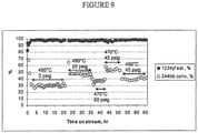
- This example illustrates the Step 3 continuous vapor phase dehydrochlorination reaction of 2-chloro-1,1,1,2-tetrafluoropropane(HCFC-244bb) 2,3,3,3-tetrafluoropropene (HFO-1234yf + HCl.
- the dehydrochlorination catalyst for the experiment was 10 wt % CsCl / 90 wt % MgF 2 .
- the feed with the composition 95GC% HCFC-244bb/3.1GC% HCFO-1233xf/ 0.35GC% HFC-245cb was introduced into the reactor at the rate of 0.45 kg/hr (1.0 lb/hr).
- the feed was vaporized prior to entering the reactor preheater.
- the feed rate was maintained constant at 0.45 kg/hr (1.0 lbs/hr) and both temperature and pressure were varied. Temperature gradient throughout the reactor never exceeded 3 - 5°C.
- the productivity of the catalyst was estimated at 48,08-96,17 kg/hr/m 3 (3 - 6 lbs/hr/ft 3 ).
- the highest productivity was observed at 470°C and 411.59 kPa (45 psig), and the lowest productivity was observed at 480°C and 122.01 kPa (3 psig).
- the reaction products were fed into a caustic scrubber to remove HCl by-product. Then the product stream was passed through a column filled with desiccant to remove residual moisture. An oil-less compressor was used to feed crude product into the distillation column that was maintained at 308.17-411.59 kPa (30 - 45 psig) pressure. Distillation was performed in a continuous mode and the take-off rate was equal to the rate of production of HFO-1234yf in the reactor. The purity of distilled HFO-1234yfwas 99.9+ GC area %.
Description
- This invention relates to novel methods for preparing fluorinated organic compounds, and more particularly to methods of producing fluorinated olefins.
- Hydrofluoroolefins (HFOs), such as tetrafluoropropenes (including 2,3,3,3-tetrafluoroprop-1-ene (HFO-1234yf)), are known to be effective refrigerants, fire extinguishants, heat transfer media, propellants, foaming agents, blowing agents, gaseous dielectrics, sterilant carriers, polymerization media, particulate removal fluids, carrier fluids, buffing abrasive agents, displacement drying agents and power cycle working fluids. Unlike chlorofluorocarbons (CFCs) and hydrochlorofluorocarbons (HCFCs), both of which potentially damage the Earth's ozone layer, HFOs do not contain chlorine and, thus, pose no threat to the ozone layer. In addition, HFO-1234yf is a low global warming compound with low toxicity and hence can meet increasingly stringent requirements for refrigerants in mobile air conditioning.
- Several methods of preparing HFOs are known. For example,
U.S. Pat. No. 4,900,874 (Ihara et al ) describes a method of making fluorine containing olefins by contacting hydrogen gas with fluorinated alcohols. Although this appears to be a relatively high-yield process, commercial scale handling of hydrogen gas at high temperature is hazardous. Also, the cost of commercially producing hydrogen gas, such as building an on-site hydrogen plant, is economically costly. -
U.S. Pat. No. 2,931,840 (Marquis ) describes a method of making fluorine containing olefins by pyrolysis of methyl chloride and tetrafluoroethylene or chlorodifluoromethane. This process is a relatively low yield process and a very large percentage of the organic starting material is converted to unwanted and/or unimportant byproducts, including a sizeable amount of carbon black which tends to deactivate the catalyst used in the process. - The preparation of HFO-1234yf from trifluoroacetylacetone and sulfur tetrafluoride has been described (See Banks, et al., Journal of Fluorine Chemistry, Vol. 82, Iss. 2, p. 171-174 (1997)). Also,
U.S. Pat. No. 5,162,594 (Krespan ) discloses a process wherein tetrafluoroethylene is reacted with another fluorinated ethylene in the liquid phase to produce a polyfluoroolefin product. - However, there remains a need for an economic means of producing hydrofluoroolefins, such as HFO-1234yf. The present invention satisfies this need among others.
-
WO2007/079431 describes a three step process to make halogenated olefins of formula CF3CF=CH2 comprising the steps of fluorinating compounds of formula C(X)2=CClC(X)3 to obtain compounds of formula C(X)2=CClCF3, fluorinating compounds of formula C(X)2=CClCF3 to obtain compounds of formula C(X)3CClYC(X)3, and subsequently dehalogenating compounds of formula C(X)3CClYC(X)3 to form the desired halogenated olefins of formula CF3CF=CHZ, wherein X, Y and Z are each independently H, F, Cl, Br or I. - Applicants have found a method for producing fluorinated organic compounds, including hydrofluoropropenes, such as HFO-1234yf. In one aspect, the present invention involves an integrated manufacturing process to produce 2,3,3,3-tetrafluoropropene from a chlorinated hydrocarbon or chlorinated olefin. Preferably, the integrated manufacturing process includes three separate reaction steps which are each optionally followed by one or more purification processes. The present invention is advantageous over other known processes for producing HFO-1234yf in that the process includes the ability to recycle unreacted starting materials to maximize raw material utilization and product yields. It also is characterized by the ability to isolate by-products that are commercially valuable.
- Accordingly, provided is a method for preparing 2,3,3,3-tetrafluoroprop-1-ene comprising: (a) providing a starting composition comprising 1,1,1,2,3-pentachloropropane (HCC-240db); (b) contacting said starting composition with a first fluorinating agent to produce a first intermediate composition comprising 2-chloro-3,3,3-trifluoropropene and a first chlorine-containing byproduct; (c) contacting said first intermediate composition with a second fluorinating agent to produce a second intermediate composition comprising 2-chloro-1,1,1,2-tetrafluoropropane; and (d) dehydrochlorinating at least a portion of said 2-chloro-1,1,1,2-tetrafluoropropane to produce a reaction product comprising 2,3,3,3-tetrafluoroprop-1-ene and a second chlorine-containing byproduct, wherein said first and second fluorinating agents are hydrogen fluoride, said method further comprising the step of separating at least a portion of said hydrogen fluoride from said 2-chloro-3,3,3-trifluoropropene subsequent to, or concurrently with, step (b) and prior to step (c), and the step of separating at least a portion of said hydrogen fluoride from said 2-chloro-1,1,1,2-tetrafluoropropane subsequent to, or concurrently with, step (c) and prior to step (d), wherein said first fluorinating agent comprises at least a portion of said hydrogen fluoride separated from said 2-chloro-3,3,3-trifluoropropene and said second fluorinating agent comprises at least a portion of said hydrogen fluoride separated from said 2-chloro-1,1,1,2-tetrafluorpropane.
-
- FIGURE 1
- is a flow diagram showing a first preferred embodiment of a first step of an integrated 3-step process for producing HFO-1234yf starting from 1,1,1,2,3-pentachloropropane;
- FIGURE 2
- is a flow diagram showing a second preferred embodiment of a first step of an integrated 3-step process for producing HFO-1234yf starting from 1,1,1,2,3-pentachloropropane;
- FIGURE 3
- is a flow diagram showing a third preferred embodiment of a first step of an integrated 3-step process for producing HFO-1234yf starting from 1,1,1,2,3-pentachloropropane;
- FIGURE 4
- is a flow diagram showing a first preferred embodiment of a second step of an integrated 3-step process for producing HFO-1234yf starting from 1,1,1,2,3-pentachloropropane;
- FIGURE 5
- is a flow diagram showing a second preferred embodiment of a second step of an integrated 3-step process for producing HFO-1234yf starting from 1,1,1,2,3-pentachloropropane;
- FIGURE 6
- is a flow diagram showing a first preferred embodiment of a third step of an integrated 3-step process for producing HFO-1234yf starting from 1,1,1,2,3-pentachloropropane; and
- FIGURE 7
- is a flow diagram showing a second preferred embodiment of a third step of an integrated 3-step process for producing HFO-1234yf starting from 1,1,1,2,3-pentachloropropane.
- FIGURE 8
- is a plot of HF as a function of temperature for HF recovery by phase separation of
Step 2, Option B, of a HCFC-244bb/HCFO-1233xf/HF mixture. - FIGURE 9
- is a plot of the selectivity ofHFO-1234yfand the percent conversion of HCFC-244bb according to certain embodiments of the invention as a function of time at various temperatures and pressures.
- According to a preferred embodiment, the present invention comprises an integrated manufacturing process for making 2,3,3,3-tetrafluoroprop-1-ene comprising:
- a) providing a
starting composition - b) contacting said starting composition with a first fluorinating agent to produce a first intermediate composition comprising 2-chloro-3,3,3-trifluoropropene and a first chlorine-containing by-product;
- c) contacting said first intermediate composition with a second fluorinating agent to produce a second intermediate composition comprising 2-chloro-1,1,1,2-tetrafluoropropane; and
- d) dehydrochlorinating at least a portion of said 2-chloro-1,1,1,2-tetrafluoropropane to produce a reaction product comprising 2,3,3,3-tetrafluoroprop-1-ene and a second chlorine-containing by-product,
- In certain embodiments, the inventive method further comprises the step of removing at least a portion of the first chlorine-containing by-product from the first intermediate composition subsequent to, and/or concurrently with, contacting step (b) and the step of removing at least a portion of the second chlorine-containing by-product from the product subsequent to, and/or concurrently with, step (d). The starting material is 1,1,1,2,3-pentachloropropane (HCC-240db)T
- Preferably, the method generally comprises at least three reaction steps. In the first step, a starting composition, comprising 1,1,1,2,3-pentachloropropane (HCC-240db), reacts with anhydrous HF, in a first vapor phase reactor (fluorination reactor) to produce a mixture of a first intermediate composition comprising HCFO-1233xf (2-chloro-3,3,3-trifluoropropene) and HC1. Preferably the reaction occurs in the presence of a catalyst, such as a fluorinated chromium oxide. The reaction is conducted in a first vapor phase reactor, preferably at a reaction temperature of about 200 - 400 °C and a reaction pressure of about 101.33-1480.28 kPa (0-200 psig). The effluent stream exiting the vapor phase reactor may optionally comprise additional components, such as un-reacted HF, heavy intermediates, and HFC-245cb.
- This reaction may be conducted in any reactor suitable for a vapor phase fluorination reaction. Preferably the reactor is constructed from materials which are resistant to the corrosive effects of hydrogen fluoride and catalyst such as Hastalloy, Inconel, Monel. In case of a vapor phase process, the reactor is filled with a vapor phase fluorination catalyst. Any fluorination catalysts known in the art may be used in this process. Suitable catalysts include, but are not limited to chromium, aluminum, cobalt, manganese, nickel and iron oxides, hydroxides, halides, oxyhalides, inorganic salts thereof and their mixtures. Combinations of catalysts suitable for the present invention nonexclusively include Cr2O3, FeCl3/C, Cr2O3/Al2O3, Cr2O3/AlF3, Cr2O3/carbon, coCl2/Cr2O3/Al2O3, NiCl2/Cr2O3/Al2O3, CoCl2/AlF3 NiCl2/AlF3 and mixtures thereof. Chromium oxide/aluminum oxide catalysts are described in
U.S. Patent No. 5,155,082 . Chromium (III) oxides such as crystalline chromium oxide or amorphous chromium oxide are preferred with amorphous chromium oxide being most preferred. Chromium oxide (Cr2O3) is a commercially available material which may be purchased in a variety of particle sizes. Fluorination catalysts having a purity of at least 98% are preferred. The fluorination catalyst is present in an excess but in at least an amount sufficient to drive the reaction. - In the second step, the first intermediate composition comprising HCFO-1233xf is converted to a second intermediate composition comprising HCFC-244bb in a liquid phase reactor by contacting the first intermediate composition with hydrogen fluoride, preferably the liquid phase reactor is TFE or PFA-lined. Preferably, the process is performed at about 70-120 °C and about 446.06-928.70 kPa (50-120 psig).
- Any liquid phase fluorination catalyst may be used in the invention. A non-exhaustive list include Lewis acids, transition metal halides, transition metal oxides, Group IVb metal halides, a Group Vb metal halides, or combinations thereof. Non-exclusive examples of liquid phase fluorination catalysts are an antimony halide, a tin halide, a tantalum halide, a titanium halide, a niobium halide, and molybdenum halide, an iron halide, a fluorinated chrome halide, a fluorinated chrome oxide or combinations thereof. Specific non-exclusive examples of liquid phase fluorination catalysts are SbCl5, SbCl3, SbF5, SnCl4, TaCls, TiCl4, NbCl5, MoCl6, FeCl3, a fluorinated species of SbCl5, a fluorinated species of SbCl3, a fluorinated species of SnCl4, a fluorinated species of TaCl5, a fluorinated species of TiCl4, a fluorinated species of NbCl5, a fluorinated species of MoCl6 a fluorinated species of FeCl3, or combinations thereof. Antimony pentachloride is most preferred.
- These catalysts can be readily regenerated by any means known in the art if they become deactivated. One suitable method of regenerating the catalyst involves flowing a stream of chlorine through the catalyst. For example, from about 0.91 to about 90.71g (about 0.002 to about 0.2 lb) per hour of chlorine can be added to the liquid phase reaction for every pound of liquid phase fluorination catalyst. This may be done, for example, for from about 1 to about 2 hours or continuously at a temperature of from about 65 °C to about 100 °C.
- In the third step, the HCFC-244bb is fed to a second vapor phase reactor (dehydrochlorination reactor) to be dehydrochlorinated to make the desired product HFO-1234yf (2,3,3,3-tetrafluoroprop-1-ene). This reactor contains a catalyst that can catalytically dehydrochlorinate HCFC-244bb to make HFO-1234yf.
- The catalysts may be metal halides, halogenated metal oxides, neutral (or zero oxidation state) metal or metal alloy, or activated carbon in bulk or supported form. When metal halides or metal oxides catalysts are used, preferably mono-, bi-, and trivalent metal halides, oxide and their mixtures/combinations, and more preferably mono-, and bi-valent metal halides and their mixtures/combinations. Component metals include, but are not limited to, Cr3+, Fe3+, Mg2+, Ca2+, Ni2+, Zn2+, Pd2+, Li+, Na+, K+, and Cs+. Component halogens include, but are not limited to, F-, Cl-, Br-, and I-. Examples of useful mono- or bi-valent metal halide include, but are not limited to, LiF, NaF, KF, CsF, MgF2, CaF2, LiCl, NaCl, KCl, and CsCl. Halogenation treatments can include any of those known in the prior art, particularly those that employ HF, F2, HCl, Cl2, HBr, Br2, HI, and I2 as the halogenation source.
- When neutral, i.e., zero valent, metals, metal alloys and their mixtures are used. Useful metals include, but are not limited to, Pd, Pt, Rh, Fe, Co, Ni, Cu, Mo, Cr, Mn, and combinations of the foregoing as alloys or mixtures. The catalyst may be supported or unsupported. Useful examples of metal alloys include, but are not limited to, SS 316, Monel 400, Inconel 825, Inconel 600, and Inconel 625.
- Preferred catalysts include activated carbon, stainless steel (e.g. SS 316), austenitic nickel-based alloys (e.g. Inconel 625), nickel, fluorinated 10% CsCl/MgO, and 10% CsCl/MgF2. The reaction temperature is preferably about 300-550 °C and the reaction pressure is preferably about 101.33-1135.54 kPa (0-150 psig). Preferably, the reactor effluent is fed to a caustic scrubber or to a distillation column to remove the by-product HCl to produce an acid-free organic product which, optionally, may undergo further purification.
- The general reaction path is provided below:
- Step 1:

- Step 2:

- Step 3:

- In addition to these three general steps, said method further comprises the step of separating at least a portion of said hydrogen fluoride from said 2-chloro-3,3,3-trifluoropropene subsequent to, or concurrently with, step (b) and prior to step (c), and the step of separating at least a portion of said hydrogen fluoride from said 2-chloro-1,1,1,2-tetrafluoropropane subsequent to, or concurrently with, step (c) and prior to step (d), wherein said first fluorinating agent comprises at least a portion of said hydrogen fluoride separated from said 2-chloro-3,3,3-trifluoropropene and said second fluorinating agent comprises at least a portion of said hydrogen fluoride separated from said 2-chloro-1,1,1,2-tetrafluorpropane. Preferred embodiments comprise one or more of the following steps:
Recycle of unreacted HF and intermediatesSubsequent to Step (1) above, the effluent stream exiting the vapor phase reactor is fed to a first recycle column. The majority of the un-reacted HF and heavy intermediates are separated from the bottom of the first recycle column and fed back to the vapor phase reactor. The lighter components, including HCl, HCFO-1233xf, HCFC-244bb, HFC-245cb, and small amounts of HF are fed to next unit operation as a crude first intermediate stream. - The HCl in the crude intermediate stream is removed using an HCl column. High purity HCl is isolated from the top of the column and absorbed in de-ionized water as concentrated HCl which, optionally, can be recovered for sale. The remaining components exit the bottom of the HCl column and are fed as a purified first intermediate stream into the liquid phase reactor of Step (2).
- Subsequent to Step (2) above, a crude second intermediate stream comprising the HCFC-244bb and HF as a reaction byproduct exits the liquid phase reactor and is fed to a second recycle column to isolate the excess HF as the bottom effluent of the column and recycle the bottoms back to the liquid phase reactor. The overhead contains mainly the HCFC-244bb and HF. The overhead stream is fed to the next unit operation.
- The overhead stream from the liquid phase recycle column that contains crude product mixture of HCFC-244bb and about 30 wt% HF is fed to a sulfuric acid extractor or a phase separator for removal of HF from this mixture. HF is either dissolved in the sulfuric acid or phase separated from the organic mixture. HF is desorbed from the sulfuric acid/HF mixture by heating and distillation and recycled back to the reactor. In case a phase separator is used, HF is phase-separated and recycled back to the reactor. The organic mixture either from the overhead of the sulfuric acid extractor or from the bottom layer of the phase separator is fed to the dehydrochlorination reactor of Step (3).
- The acid-free organic product produced in Step (3) is fed to one or more, preferably two, distillation columns for purification of final product. The first column is used to remove the lighter components and the second column is used to purify the final product, HFO-1234yf. The un-reacted HCFC-244bb and HCFO-1233xf are isolated from the bottom of the second distillation column and recycled back to the second step (hydrofluorination of HCFO-1233xf).
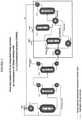
- Referring to
Figure 1 , shown is a preferred embodiment ofoperations 1 through 3. Here, HCC-240db and excess HF are simultaneously fed to a vaporizer HX-1A-1 and then into a vapor phase reactor R-1A-1. The reaction temperature is about 200 - 400 °C and the reaction pressure is about 101.33-1480.28 kPa (0-200 psig). The catalyst in R-1A-1 is fluorinated chromium oxide. The reactor effluent comprising unreacted HCC-240db, partially fluorinated intermediates and by-products, overfluorinated by-products, HF, HCFO-1233xf, and HCl, then enters recycle column D-1A1 where a stream comprising mainly unreacted HCC-240db, partially fluorinated intermediates, and the majority of the HF exits the bottom of the recycle column and is recycled back to theStep 1 reactor R-1A-1 via vaporizer HX-1A-1. A stream consisting of mainly HCFO-1233xf, HF, and HCl exits the top of the recycle column and enters HCl column 01 A-2. A stream consisting of mainly HCl by-product exits the top of the HCl column and is fed to an HCl recovery system. The recovered HCl by-product can be sold for profit. The HCl column bottoms consisting mainly of HCFO-1233xf and HF are then fed into an HF recovery system. The HF recovery system starts with the HCFO-1233xf/HF stream being vaporized in heat exchanger HX-1A-2 and fed into HF absorption column A-1A-1. Here a liquid stream of 50 - 80% H2SO4 contacts the gaseous HCFO-1233xf/HF stream and absorbs the majority of the HF. The stream exiting the bottom of A-1A-1 consists of HF/H2SO4/H2O and is fed to heat exchanger HX-1A-3 where it is heated to a temperature sufficient to flash the majority of the HF along with small amounts of H2O and H2SO4. This stream is fed to HF recovery distillation column D-1A-3. The liquid remaining after the HF is flashed off in HX-1A-3 consisting mainly of H2SO4 and H2O (with 0 - 4% HF) is cooled in HX-1A4 and recycled back to HF absorption column A-1A-1. The HF recovery column, D-1A3, bottoms stream consisting of mainly H2SO4 and H2O are recycled back to heat exchanger HX-1A-3. Anhydrous HF is recovered from the top of the HF recovery column, D-1A-3, and is recycled back to theStep 1 reactor R-1A-1 via vaporizer HX-1A-1. The stream exiting the top of HF absorption column A-1A-1 consisting of mainly HCFO-1233xf (trace HF) is sent forward toStep 2. Optionally, before being sent forward to step 2, the stream is fed to a polishing system A-1A-2 where the gaseous stream contacts a water or a caustic solution to remove trace HF and is subsequently dried with a desiccant. After deactivation of the catalyst in reactor R-1A-1 it can be regenerated in-situ by heating to 300 - 400 °C and passing an oxidizing agent such as 02 or Cl2 over it for a prescribed period of time. - Referring to
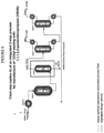
Figure 2 , shown is another preferred embodiment ofoperations 1 through 3. Here, HCC-240db and excess HF are simultaneously fed to a vaporizer HX-1B-1 and then into a vapor phase reactor R-1B-1. The reaction temperature is about 200 - 400 °C and the reaction pressure is about 101.33-1480.28 kPa (0 - 200 psig). The catalyst in R-1B-1 is fluorinated chromium oxide. The reactor effluent consisting of unreacted HCC-240db, partially fluorinated intermediates and by-products, overfluorinated by-products, HF, HCFO-1233xf, and HCl, then enters recycle column D-1B-1 where a stream consisting of mainly unreacted HCC-240db, partially fluorinated intermediates, and the majority of the HF exits the bottom of the recycle column and is recycled back to theStep 1 reactor R-1B-1 via vaporizer HX-1B-1. A stream consisting of mainly HCFO-1233xf, HF, and HCl exits the top of the recycle column and enters HCl column D-1B-2. A stream consisting of mainly HCl by-product exits the top of the HCl column and is fed to an HCl recovery system. The recovered HCl by-product can be sold for profit. The HCl column bottoms consisting mainly of HCFO-1233xf and HF are then fed into an HF recovery system. The HF recovery system starts with the HCFO-1233xf/HF stream being fed into phase separation system PS-1B-1. Here the stream is cooled to -40 - 0 °C. The HF rich top layer (<10% HCFO-1233xf) is recycled back to the recycle column D-1B-1. The organic rich bottom layer containing mainly HCFO-1233xf (< 4% HF) is sent forward toStep 2. Optionally, before being sent forward toStep 2, the stream is fed to a distillation column D-1B-3. A stream consisting of mainly HCFO-1233xf/HF azeotrope exits the top of the column and is recycled back to theStep 1 phase separator, PS-1B-1. The column bottoms consisting mainly of HCFO-1233xf are sent forward toStep 2. After deactivation of the catalyst in reactor R-18-1 it can be regenerated in-situ by heating to 300 - 400 °C and passing an oxidizing agent such as O2 or Cl2 over it for a prescribed period of time. - Referring to
Figure 3 , shown is another preferred embodiment ofoperations 1 through 3. Here, HCC-240db and excess HF are simultaneously fed to a vaporizer HX-1C-1 and then into a vapor phase reactor R-1C-1. The reaction temperature is about 200 - 400 °C and the reaction pressure is about 101.33-1480.28 kPa (0 - 200 psig). The catalyst in R-1C-1 is fluorinated chromium oxide. The reactor effluent consisting of unreacted HCC-240db, partially fluorinated intermediates and by-products, overfluorinated by-products, HF, HCFO-1233xf, and HCl, then enters recycle column D-1C-1 where a stream consisting of mainly unreacted HCC-240db, partially fluorinated intermediates, and the majority of the HF exits the bottom of the recycle column and is recycled back to theStep 1 reactor R-1C-1 via vaporizer HX-1C-1. A stream consisting of mainly HCFO-1233xf, HF, and HCl exits the top of the recycle column and enters HCl column D-1C-2. A stream consisting of mainly HCl by-product exits the top of the HCl column and is fed to an HCl recovery system. The recovered HCl by-product can be sold for profit. The HCl column bottoms consisting mainly of HCFO-1233xf and HF are then sent forward toStep 2 without removal of HF. After deactivation of the catalyst in reactor R-1C-1 it can be regenerated in-situ by heating to 300 - 400 °C and passing an oxidizing agent such as O2 or Cl2 over it for a prescribed period of time. - Referring to
Figure 4 , shown is a preferred embodiment ofoperations 4 through 6. Here, the HCFO-1233xf containing stream fromStep 1, Options A, B, or C and excess HF are simultaneously fed to a vaporizer HX-2A-1 and then into a liquid phase reactor R-2A-1. R-2A-1 is a TFE or PFA-lined liquid phase reactor, run at 70 - 120 °C and 446.06-028.70 kPa (50 - 120 psig). The catalyst in R-2A-1 is SbCl5 or other Lewis acid catalyst. A catalyst stripper column CS-2A-1 is connected to the reactor, R-2A-1, and serves the purpose of knocking down and returning entrained catalyst, some HF, and some unreacted HCFO-1233xf back to the reactor for further reaction. Cl2 may also be fed to the reactor to keep the catalyst active. It may be fed continuously or batchwise as needed. The stream exiting the top of catalyst stripper CS-2A-1 consisting mainly of HCFC-244bb and HF (plus small amounts of unreacted HCFO-1233xf and Cl2 may also be present) is fed to a recycle column D-2A-1 where a stream consisting of mainly HF (trace organic) exits the bottom of the recycle column and is recycled back to theStep 2 reactor R-2A-1 via vaporizer HX-2A-1. A stream consisting of mainly HCFC-244bb and HF (plus small amounts of unreacted HCFO-1233xf and Cl2 may also be present) exits the top of the recycle column and is then fed into an HF recovery system. The HF recovery system starts with the gaseous HCFC-244bb and HF (plus small amounts of unreacted HCFO-1233xf and Cl2 may also be present) stream being fed into HF absorption column A-2A-1. Here a liquid stream of 50 - 80% H2SO4 contacts the gaseous HCFC-244bb/HF stream and absorbs the majority of the HF. The stream exiting the bottom of A-2A-1 consists of HF/H2SO4/H2O and is fed to heat exchanger HX-2A-2 where it is heated to a temperature sufficient to flash the majority of the HF along with small amounts of H2O and H2SO4. This stream is fed to HF recovery distillation column D-2A-3. The liquid remaining after the HF is flashed off in HX-2A-2 consisting mainly of H2SO4 and H2O (with 0 - 4% HF) is cooled in HX-2A-3 and recycled back to HF absorption column A-2A-1. The HF recovery column, D-2A-3, bottoms stream consisting of mainly H2SO4 and H2O are recycled back to heat exchanger HX-2A-2. Anhydrous HF is recovered from the top of the HF recovery column, D-2A-3, and is recycled back to theStep 2 reactor R-2A-1 via vaporizer HX-2A-1. The stream exiting the top of HF absorption column A-2A-1 consisting of mainly HCFC-244bb (plus small amounts of unreacted HCFO-1233xf and Cl2 may also be present) is sent forward toStep 3. Optionally, before being sent forward toStep 3, the stream is fed to a polishing system A-2A-2 where the gaseous stream contacts a water or a caustic solution (and bisulfite as needed to destroy any Cl2) to remove trace HF and is subsequently dried with a desiccant. - Another option is to add a Cl2 recovery distillation column, D-2A-2 and heat exchanger HX-2A-4 after the recycle column D-2A-1 and before HF recovery. The stream exiting the top of the recycle column is fed into the Cl2 recovery column and Cl2 is taken overhead and recycled back to the
Step 2 reactor, R-2A-1. The Cl2 recovery column bottom stream consisting of mainly HCFC-244bb and HF (plus small amount of unreacted HCFO-1233xf) is vaporized in heat exchanger HX-2A-4 and fed to the HF recovery system described above. This eliminates the need for bisulfite in the optional HCFC-244bb polishing system. - Referring to
Figure 5 , shown is another preferred embodiment ofoperations 4 through 6. Here, the HCFO-1233xf containing stream fromStep 1, Options A, B, or C and excess HF are simultaneously fed to a vaporizer HX-2B-1 and then into a liquid phase reactor R-2B-1. R-2B-1 is a TFE or PFA-lined liquid phase reactor, run at 70 - 120 °C and 446.06-928.70 kPa (50 - 120 psig). The catalyst in R-2B-1 is SbCl5 or other Lewis acid catalyst. A catalyst stripper column CS-2B-1 is connected to the reactor, R-2B-1, and serves the purpose of knocking down and returning entrained catalyst, some HF, and some unreacted HCFO-1233xf back to the reactor for further reaction. Cl2 may also be fed to the reactor to keep the catalyst active. It may be fed continuously or batchwise as needed. The stream exiting the top of catalyst stripper CS-2B-1 consisting mainly of HCFC-244bb and HF (plus small amounts of unreacted HCFO-1233xfand Cl2 may also be present) ) is fed to a recycle column D-2B-1 where a stream consisting of mainly HF (trace organic) exits the bottom of the recycle column and is recycled back to theStep 2 reactor R-2B-1 via vaporizer HX-2B-1. A stream consisting of mainly HCFC-244bb and HF (plus small amounts of unreacted HCFO-1233xf and Cl2 may also be present) exits the top of the recycle column and is then fed to a Cl2 recovery distillation column, D-28-2. The stream exiting the top of the recycle column is fed into the Cl2 recovery column and 012 is taken overhead and recycled back to theStep 2 reactor, R-2B-1. The Cl2 recovery column bottom stream consisting of mainly HCFC-244bb and HF (plus small amount of unreacted HCFO-1233xf) is then fed into an HF recovery system. The HF recovery system starts with the HCFC-244bb/HF stream being fed into phase separation system PS-2B-1. Here the stream is cooled to -40 - 0 °C. The HF rich top layer (<10% HCFC-244bb) is recycled back to the recycle column D-2B-1. The organic rich bottom layer containing mainly HCFC-244bb (<4% HF + small amount of HCFO-1233xf) is sent forward toStep 3. Optionally, before being sent forward toStep 3, the stream is fed to a distillation column D-2B-3. A stream consisting of mainly HCFC-244bb/HF azeotrope (plus small amount ofHCFO-1233xf) exits the top of the column and is recycled back to theStep 2 reactor, R-2B-1, via a vaporizer HX-213-1. - Referring to
Figure 6 , shown is a preferred embodiment of operations 7 through 8. Here, the HCFC-244bb-containing stream fromStep 2, Options A or B, are fed to a vaporizer HX-3A-1 and then into a vapor phase reactor R-3A-1. The reaction temperature is about 350 - 550 °C and the reaction pressure is about 101.33-1135.54 kPa (0 - 150 psig). The following catalysts have been shown to have high selectivity for producing HFO-1234yf in the range of temperatures mentioned above and can be used in R-3A-1: activated carbon, stainless steel (e.g. SS 316), austenitic nickel-based alloys (e.g. Inconel 625), nickel, fluorinated 10% CsCl/MgO, and 10% CsCl/MgF2. The reactor effluent consisting of unreacted HCFC-244bb, HCFO-1233xf, HFO-1234yf, HCl (plus HF and/or Cl2 ifcertain Step 2 options were employed) then enters acid absorption system A-3A-1 where the gaseous stream contacts a water or a caustic solution (and bisulfite to destroy Cl2 if present) to remove HCl (and HF if present) and is subsequently dried with a desiccant. The gas exiting the top of the acid absorber is fed to a "lights" distillation column D-3A-1. Non-condesables and byproducts having lower boiling points than HFO-1234yf exit the top of the "lights" column and are fed to a thermal-oxidizer and eliminated/destroyed. The bottoms from the "lights" column are fed to a HFO-1234yf product column D-3A-2. Product grade HFO-1234yf exits the top of the column to product storage. The product column bottoms consist mainly of unreacted HCFC-244bb and HCFO-1233xf and are recycled back toStep 2 reactor R-2A-1 or R-2B-1 depending on what option that is being employed. - Referring to
Figure 7 , shown is another preferred embodiment of operations 7 through 8. Here, the HCFC-244bb containing stream fromStep 2, Options A or B, are fed to a vaporizer HX-3A-1 and then into a vapor phase reactor R35-1. The reaction temperature is about 350 - 550 °C and the reaction pressure is about 101.33-1135.54 kPa (0 - 150 psig). The following catalysts have been shown to have high selectivity for producing HFO-1234yf in the range of temperatures mentioned above and can be used in R-3B-1: activated carbon, stainless steel (e.g. SS 316), austenitic nickel-based alloys (e.g. Inconel 625), nickel, fluorinated 10% CsCl2/MgO, and 10% CsCl2/MgF2. The reactor effluent consisting of unreacted HCFC-244bb, HCFO-1233xf, HFO-1234yf, HCl (plus HF and/or Cl2 ifcertain Step 2 options were employed) enters HCl column D-313-1. A stream consisting of mainly HCl by-product exits the top of the HCl column and is fed to an HCl recovery system. The recovered HCl by-product can be sold for profit. The HCl column bottoms consisting mainly of unreacted HCFC-244bb, HCFO-1233xf, and HFO-1234yf (plus HF and/or Cl2 ifcertain Step 2 options were employed) are then fed to a "lights" distillation column D-3B-2. By-products having lower boiling points than HFO-1234yf exit the top of the "lights" column and are fed to a thermal-oxidizer and eliminated/destroyed. The bottoms from the "lights" column are fed to a HFO-1234yf product column D-38-3. Product grade HFO-1234yf exits the top of the column to product storage. The product column bottoms consist mainly of unreacted HCFC-244bb and HCFO-1233xf and are recycled back toStep 2 reactor R-2A-1 or R-2B-1 depending on what option that is being employed. - Optionally, if HF and/or Cl2 are present in the HCl column, D-3B-1, they will exit from the bottom of the column. The bottom stream is then vaporized by HX-3B-2 and fed to acid absorption system A-3B-1 where the gaseous stream contacts a water or a caustic solution (and bisulfite to destroy Cl2 if present) to remove HF (and HCl if present) and is subsequently dried with a desiccant. The gas exiting the top of the acid absorber is fed to the "lights" column D-3B-2.
- The invention is further described in terms of the following, non-limiting examples.
- This example illustrates
Step 1 of the continuous vapor phase fluorination reaction of 1,1,2,3-tetrachloropropene (TCP) + 3HF → 2-chloro-3,3,3-trifluoropropene (HCFO-1233xf) + 3HCl. The fluorination catalyst for the experiment was fluorinated Cr2O3. - A continuous vapor phase fluorination reaction system consisting of N2, HF, and organic feed systems, feed vaporizer, superheater, 4 inch ID Monel reactor, acid scrubber, drier, and product collection system was used to study the reaction. The reactor was loaded with 9415.2 grams of pretreated Cr2O3 catalyst which equates to about 6.5 liters of catalyst. The reactor was then heated to a reaction temperature of about 235 °C with a N2 purge going over the catalyst after the reactor had been installed in a constant temperature sand bath. The reactor was at about 20.7 kPa (3 psig) of pressure. HF feed was introduced to the reactor (via the vaporizer and superheater) as a co-feed with the N2 for 15 minutes when the N2 flow was stopped. The HF flow rate was adjusted to 635 g/hr (1.4 Ib/hr) and then 1,1,2,3-tetrachloropropene (TCP) feed was started to the reactor (via the vaporizer and superheater). The feed rate of TCP was kept steady at about 363 g/hr (0.8 Ib/hr) and HF feed was kept steady at 635 g/hr (1.4 Ib/hr) for about a 15 to 1 mole ratio of HF to TCP. Once the reaction started the catalyst bed temperature rose to a range of 250 - 260 °C. The contact time at 250 - 260 °C, 20.7 kPa (3 psig) and the above feed rates was calculated to be about 16 seconds. The average composition of the material that was collected over 500 hours of on-stream time was about 97.2 GC area % HCFO-1233xf, 1.6 GC area % HCFC- 244bb, 0.6 GC area % HFO-1234yf/HFC-245cb, 0.1 GC area % HCFO-1223xd, and 0.08 GC area % HCFO-1231. After 500 hours an under-fluorinated intermediate, 2,3- dichloro-3,3-difluoropropene (HCFO-1232xf) started to appear as the selectivity to HCFO-1233xf decreased when the catalyst started losing activity. When the selectivity to HCFO-1233xf decreased to about 83% and the selectivity to underfluorinated intermediate HCFO-1232xf increased to about 15% after 650 hours of on-stream time, the reaction was stopped due to loss of catalyst activity. The conversion of TCP remained at > 99% throughout the run.
- This example illustrates the
Step 1 continuous vapor phase fluorination reaction of 1,1,1,2,3-pentachloropropane (HCC-240db) + 3HF→ 2-chloro-3,3,3-trifluoropropene (HCFO-1233xf) + 4HCl. The fluorination catalyst for the experiment was fluorinated Cr2O3. - The same continuous vapor phase fluorination reaction system as described in Reference Example 1 was used for Example 2. The HCC-240db + 3HF → HCFO-1233xf + 4HCl reaction was run at a 15:1 mole ratio HF to HCC-240db, contact time of 15 seconds, and a reaction temperature of 255 °C. GC analysis of the reactor effluent showed 100% conversion of HCC-240db and 98.3% selectivity of HCFO-1233xf on a molar basis. The details of Example 3 are presented in Table 1.
Table 1 Exp# 71 HCC-240db + 3HF → HCFO- 1233xf + 4 HCl
Fluorinated Cr2O3 catalyst, 15:1 mole ratio HF to HCC-240db,contact time 15 seconds, Reaction Temperature = 255 °C.Component HFO-1234yf/HFC-245cb HCFC-244bb HCFO -1233xf * HCC-240db others Selectivity 0.5 0.6 98.3 100.0 0.6 * Conversion - This example illustrates
Step 2 of the continuous liquid phase fluorination reaction of 2-chloro-3,3,3-trifluoro-propene (HCFO-1233xf) + HF → 2-chloro-1,1,1,2-tetrafluoropropane (HCFC-244bb). The fluorination catalyst for the experiment was ShCl5. - About 5618 grams of SbCl5 were contained in a Teflon TM-lined liquid phase reactor equipped with a 2-inch ID (inside diameter) packed column and a condenser. The reactor was 2.75-inch ID x 36-inch L (length). Initially, a greater than 5:1 mole ratio of HF was added to the reactor to fluorinate the catalyst A greater than 3:1 mole ratio of Cl2 was then added to the reactor to ensure that the catalyst was brought back to a pentavalent state. The reactor was heated to about 85 °C - 87 °C. HF feed was started first. When an additional 0.68 kg (1.5 lbs) of HF had been added the 2-chloro-3,3,3-trifluoropropene feed was started. The purity of the 2-chloro-3,3,3-trifluoropropene feed stock was about 97.3 GC (gas chromatograph) area %. The experiment ran continuously for about 162 hours. For this run, chlorine was fed batchwise about every 4 hours throughout the run to keep the catalyst active.
- Conversion was immediately above 98%, and remained that way throughout the rest of the run. The average feed rates of HF and HCFO-1233xf were 0.41 and 0.40 kg/hr (0.91 and 0.881 b/hr) respectively. The chlorine additions amounted to about 3.0% by weight of the average organic feed rate. About 55.79 kg (123 pounds) of acid-free 2-chloro-1,1,1,2-tetrafluoropropane crude were collected.
- The reactor temperature range for the experiments was 78° C - 86° C and the pressure range was 583.96 and 825.27 kPa (70 psig - 105 psig). The reaction was monitored by sampling the reactor effluent stream periodically. The samples were analyzed on a gas chromatograph. The average conversion of 2-chloro-3,3,3-trifluoropropene (HCFO-1233xf) of about 98% and the following average product selectivity: HCFC-244bb = 90%, HCFO-1223xd = 1% and HFC-245cb = 8%.
- This example illustrates the recovery of anhydrous HF from a mixture of HF and HCFC-244bb according to certain preferred embodiments of the present invention.
- A mixture consisting of about 75 wt.% HCFC-244bb and about 25 wt% HF is vaporized and fed to the bottom of a packed column at a feed rate of about 1.32 kg (2.9 lbs) per hour for about 4 hours. A stream of about 80wt.% sulfuric acid (80/20 H2SO4/H20) with about 2% HF dissolved therein is fed continuously to the top of the same packed column at a feed rate of about 2.54 kg (5.6 lbs) per hour during the same time frame. A gaseous stream exiting the top of the column comprises HCFC-244bb with less than 1.0 wt.% HF therein. The concentration of HF in the sulfuric acid in the column bottoms increases from 2.0 wt.% to about 15 wt.%.
- The column bottoms containing sulfuric acid and about 15 wt.% HF are collected and charged into a 9.09 L (2 gallon) teflon vessel. The mixture is heated to about 140 °C to vaporize and flash off HF product, which is collected. The collected HF product contains about 6000 ppm water and 500 ppm sulfur.
- The HF collected from flash distillation is distilled in a distillation column and anhydrous HF is recovered. The recovered anhydrous HF contains less than 50 ppm of sulfur impurities and less than 100 ppm water.
- This example demonstrates the optional HF recovery distillation of
Step 1, Option B after the recovery of the majority of the HF by phase separation. The distillation column feed is a mixture of HF, HCFO-1233xf, and HCFC-244bb. - After phase separation, 16.96 kg (37.4 pounds) of a mixture containing 3 weight percent HF, 43.1 weight percent HCFC-244bb and 53.9 weight percent HCFO-1233xf was charged into a distillation column. The distillation column consisted of a 45.46 L (10 gallon) reboiler, 2 inch ID by 10 foot propack column, and a shell and tube condenser. The column had about 30 theoretical plates. The distillation column was equipped with temperature, pressure, and differential pressure transmitters. The distillation was run at a pressure of about 259.93-273.72 kPa (37.7 - 39.7 psia). The distillate was sampled, titrated for HF concentration determination, and analyzed by GC at regular intervals. Titration showed an HF concentration in the range of 25 - 33 wt% (using titration with 0.1 N KOH). The organic concentrations based on GC area % were about 17 - 21 GC area% HCFC-244bb and about 79 - 83 GC area% HCFO-1233xf. At 259.93 kPa (37.7 psia) the column overhead temperature was about 23 °C for this composition. When the HF was depleted, as confirmed by titration, the column overhead temperature was about 40 °C at 259.90 kPa (23 psig). 3.63 kg (8.0 lbs) of HF containing distillate was collected into a DIT and 13.34 kg (29.4 lbs) of HF free HCFO-1233xf/HCFC-244bb mixture was drained from the reboiler.
- This example demonstrates the recycle column of
Step 2, Options A and B. - A reactor effluent mixture from a
reaction Step 2 experiment was charged into a distillation column. The distillation column consisted of a 45.46 L (10 gallon) reboiler, 2 inch ID by 10 foot propack column, and a shell and tube condenser. The column had about 30 theoretical plates. The distillation column was equipped with temperature, pressure, and differential pressure transmitters. The distillation column feed mixture was about 71.5 wt% HF and 28.5 wt% organic. The organic was mostly a mixture of HCFO-1233xf and HCFC-244bb, but contained some light and heavy impurities and some HCFO-1232xf intermediate. The distillation was run at a pressure of about 790.80 kPa (100 psig). The distillate was sampled, titrated for HF concentration determination, and analyzed by GC at regular intervals. Titration showed an HF concentration in the range of 20 - 30 wt% (using titration with 0.1 N KOH). In total 17.24 kg (38 lbs) of distillate was collected that contained about 20 - 30 wt% HF. The balance was organic having an average GC analysis of 54.5% HCFO-1233xf, 44.5% HCFC-244bb, and 1% light impurities with only ppm levels of higher boiling impurities. The reboiler bottoms were drained to a separate 45.36 kg (100 lb) cylinder with a Ceodeux dual valve assembly and dip tube. 28.12 kg (62 lbs) of mainly HF were recovered. Some intermediate HCFO-1232xf and high boiling impurities were observed. The recovered HF (reboiler bottoms) was used to demonstrate recycle in asubsequent Step 2 reaction and worked satisfactorily. - This example demonstrates the HF recovery by phase separation of
Step 2, Option B, of a HCFC-244bb/HCFO-1233xf/HF mixture. - The separation of organic and HF layers was tested in the temperature range from +10 °C to -30 °C. The highest concentration of HF in the organic layer was detected at +10 °C (2.23 ± 0.30 wt.%), the lowest concentration of HF in the organic layer was detected at -30°C (0.76 t 0.09 wt.%). The concentration of HF in the HF layer was about 90 ± 5 wt. %. GC analysis of Organic and HF layers indicated that there is no difference in the organic composition between organic and HF layer.
- The phase-separation of the mixture containing HCFC-244bb, HCFO-1233xf, and HF was performed in the temperature range of -30 °C to +10 °C. A 500m1 SS sample cylinder was used for the study. The temperature of the cylinder was controlled with ethanol circulating through the coil wrapped around the cylinder. A thermocouple was attached to the outside wall of the cylinder (between cooling coil and the cylinder wall) and positioned in the middle of the cylinder to measure the temperature. The cylinder was also equipped with sampling valves at the bottom and the top of the cylinder. To the cylinder were charged 98.7 g of anhydrous HF and 233 g of a 93.0 GC area % HCFC-244bb/ 5.0 GC area % HCFO-1233xf mixture. The weight ratio of HF to Organic was 29.8:70.2. The cylinder was padded with nitrogen to 184.06 kPa (12 psig) at -30 °C to allow sampling. Samples were taken from the bottom of the cylinder into Tedlar gas sample bags that contained 5 grams of distilled water for the purpose of absorbing HF. The first sample was taken two hours after the cylinder reached the desired temperature. After this, the contents of the cylinder were mixed and a second sample was taken five minutes after mixing. HF concentration was determined by titration with 0.1 N KOH of the aqueous phase of the sample bags. HF concentration in samples taken after 2 hours at given temperature is presented in Table 2. HF concentration in samples taken 5 minutes after mixing contents of the cylinder at given temperature is presented in Table 3.
- HF concentration in the HF layer was analyzed after organic layer was removed from the system. KOH titration showed that concentration of HF in the acid layer was about 90 ± 5%. The distribution of organics in HF layer was the same as in the Organics layer.
Table 2. HF concentration in the samples of the bottom (organic) phase taken after equilibrating the contents of the phase-separator for 2 hours at given temperature. Temperature
(°C)HF concentration in bottom (organic) phase
(wt.%)Standard deviation -30 0.76 0.09 -20 0.89 0.13 -10 1.25 0.11 0 1.63 0.15 10 2.23 0.30 Table 3. HF concentration in the samples of the bottom (organic) phase taken 5 minutes after mixing the contents of the phase-separator. Temperature
(°C)HF concentration in bottom (organic) phase
(wt.%)Standard deviation -30 0.84 0.08 -20 1.05 0.26 -10 1.37 0.07 0 1.71 0.22 10 2.61 0.35 - The HF concentration is shown graphically
Fig. 8 . - This example illustrates the
Step 3 continuous vapor phase dehydrochlorination reaction of 2-chloro-1,1,1,2-tetrafluoropropane(HCFC-244bb) 2,3,3,3-tetrafluoropropene (HFO-1234yf + HCl. The dehydrochlorination catalyst for the experiment was 10 wt % CsCl / 90 wt % MgF2. - Conversion of HCFC-244bb into HFO-1234yf was performed using Monel reactor (
ID 5,08 cm (2 inches), length 81,28 cm (32 inches)) equipped with a Monel preheater (ID 2,54 cm (1 inch), length 81,28 cm (32 inches)) which was filled with Nickel mesh to enhance heat transfer. The reactor was filled with 2.0 liters of pelletized 10wt%CsCl/90wt% Mg F2 dehydrochlorination catalyst. Nickel mesh was placed at the top and at the bottom of reactor to support the catalyst. A multi-point thermocouple was inserted at the center of the reactor. The catalyst was pretreated in dry N2 flow for 6 hours at the temperature of 480°C. Then the feed with the composition 95GC% HCFC-244bb/3.1GC% HCFO-1233xf/ 0.35GC% HFC-245cb was introduced into the reactor at the rate of 0.45 kg/hr (1.0 lb/hr). The feed was vaporized prior to entering the reactor preheater. The feed rate was maintained constant at 0.45 kg/hr (1.0 lbs/hr) and both temperature and pressure were varied. Temperature gradient throughout the reactor never exceeded 3 - 5°C. The productivity of the catalyst was estimated at 48,08-96,17 kg/hr/m3 (3 - 6 lbs/hr/ft3). The highest productivity was observed at 470°C and 411.59 kPa (45 psig), and the lowest productivity was observed at 480°C and 122.01 kPa (3 psig). The reaction products were fed into a caustic scrubber to remove HCl by-product. Then the product stream was passed through a column filled with desiccant to remove residual moisture. An oil-less compressor was used to feed crude product into the distillation column that was maintained at 308.17-411.59 kPa (30 - 45 psig) pressure. Distillation was performed in a continuous mode and the take-off rate was equal to the rate of production of HFO-1234yf in the reactor. The purity of distilled HFO-1234yfwas 99.9+ GC area %. GC analysis of the distillate showed the presence of ppm levels of light impurities The bottoms of the distillation column were discharged and recycled into the dehydrochlorination reactor. 480°C
at 122.01 kPa (3 psig) - HCFC-244bb conversion -30%, Selectivity to HFO-1234yf -97%
480°C at 239.22 kPa (20 psig) - HCFC-244bb conversion -47%, Selectivity to HFO-1234yf - 96% 470°C
at 239.22 kPa (20 psig) - HCFC-244bb conversion -36%, Selectivity to HFO-1234yf - 97%
470°C at 411.59 kPa (45 psig) - HCFC-244bb conversion -53%, Selectivity to HFO-1234yf -96%
460°C at 411.59 kPa (45 psig) - HCFC-244bb conversion -38%, Selectivity to HFO-1234yf -98%
Reaction Conditions: Feed = about 95 GC% HCFC-244bb; about 3.1 GC% HCFO-1233xf; and about 0.35 GC% HFC-245cb; 2.0 liters of 10wt% CsCl/90 wt% Mg F2 catalyst; 0.45 kg/hr (1.0 lb/hr) feed rate. The reaction data is represented graphically inFig. 9 . - It should be understood that the foregoing description is only illustrative of the present invention.
Claims (7)
- A method for preparing 2,3,3,3-tetrafluoroprop-1-ene comprising:a) providing a starting composition comprising 1,1,1,2,3-pentachloropropane (HCC-240db);b) contacting said starting composition with a first fluorinating agent to produce a first intermediate composition comprising 2-chloro-3,3,3-trifluoropropene and a first chlorine-containing by-product;c) contacting said first intermediate composition with a second fluorinating agent to produce a second intermediate composition comprising 2-chloro-1,1,1,2-tetrafluoropropane; andd) dehydrochlorinating at least a portion of said 2-chloro-1,1,1,2-tetrafluoropropane to produce a reaction product comprising 2,3,3,3-tetrafluoroprop-1-ene and a second chlorine-containing by-product,wherein said first and second fluorinating agents are hydrogen fluoride, said method further comprising the step of separating at least a portion of said hydrogen fluoride from said 2-chloro-3,3,3-trifluoropropene subsequent to, or concurrently with, step (b) and prior to step (c), and the step of separating at least a portion of said hydrogen fluoride from said 2-chloro-1,1,1,2-tetrafluoropropane subsequent to, or concurrently with, step (c) and prior to step (d),
wherein said first fluorinating agent comprises at least a portion of said hydrogen fluoride separated from said 2-chloro-3,3,3-trifluoropropene and said second fluorinating agent comprises at least a portion of said hydrogen fluoride separated from said 2-chloro-1,1,1,2-tetrafluorpropane. - The method of claim 1 further comprising the step of removing at least a portion of said first chlorine-containing by-product from said first intermediate composition subsequent to, and/or concurrently with, said contacting step (b) and the step of removing at least a portion of said second chlorine-containing by-product from said product subsequent to, and/or concurrently with, said step (d).
- The method of claim 1, wherein said contacting step (b) comprises a vapour-phase catalytic fluorination of HCC-240db.
- The method of claim 1, wherein said contacting step (c) comprises a liquid-phase fluorination of said 2-chloro-3,3,3-trifluoropropene in the presence of a catalyst.
- The method of claim 1, wherein said dehydrochlorination step (d) is conducted in the vapour phase and in the presence of a catalyst.
- The method of claim 1, wherein step (b) comprises a vapour phase catalytic fluorination of HCC-240db; step (c) comprises a liquid phase catalytic fluorination of HCFO-123xf; and step (d) is conducted in the vapour phase and in the presence of a catalyst.
- The method of claim 1, wherein the first fluorinating agent is HF and wherein the first chlorine-containing by-product is HCl.
Priority Applications (3)
| Application Number | Priority Date | Filing Date | Title |
|---|---|---|---|
| PL12194295T PL2583959T3 (en) | 2008-03-20 | 2009-03-16 | Integrated process to produce 2,3,3,3-tetrafluoropropene |
| EP12194295.7A EP2583959B1 (en) | 2008-03-20 | 2009-03-16 | Integrated process to produce 2,3,3,3-tetrafluoropropene |
| EP20163392.2A EP3722273A1 (en) | 2008-03-20 | 2009-03-16 | Integrated process to produce 2,3,3,3-tetrafluoropropene |
Applications Claiming Priority (2)
| Application Number | Priority Date | Filing Date | Title |
|---|---|---|---|
| US3832708P | 2008-03-20 | 2008-03-20 | |
| US12/404,130 US8058486B2 (en) | 2004-04-29 | 2009-03-13 | Integrated process to produce 2,3,3,3-tetrafluoropropene |
Related Child Applications (5)
| Application Number | Title | Priority Date | Filing Date |
|---|---|---|---|
| EP12194295.7A Division EP2583959B1 (en) | 2008-03-20 | 2009-03-16 | Integrated process to produce 2,3,3,3-tetrafluoropropene |
| EP12194295.7A Division-Into EP2583959B1 (en) | 2008-03-20 | 2009-03-16 | Integrated process to produce 2,3,3,3-tetrafluoropropene |
| EP20163392.2A Division-Into EP3722273A1 (en) | 2008-03-20 | 2009-03-16 | Integrated process to produce 2,3,3,3-tetrafluoropropene |
| EP20163392.2A Division EP3722273A1 (en) | 2008-03-20 | 2009-03-16 | Integrated process to produce 2,3,3,3-tetrafluoropropene |
| EP12194295.7 Division-Into | 2012-11-26 |
Publications (4)
| Publication Number | Publication Date |
|---|---|
| EP2103587A2 EP2103587A2 (en) | 2009-09-23 |
| EP2103587A3 EP2103587A3 (en) | 2010-03-03 |
| EP2103587B1 EP2103587B1 (en) | 2013-02-20 |
| EP2103587B2 true EP2103587B2 (en) | 2022-01-19 |
Family
ID=40756416
Family Applications (3)
| Application Number | Title | Priority Date | Filing Date |
|---|---|---|---|
| EP20163392.2A Pending EP3722273A1 (en) | 2008-03-20 | 2009-03-16 | Integrated process to produce 2,3,3,3-tetrafluoropropene |
| EP09155292.7A Active EP2103587B2 (en) | 2008-03-20 | 2009-03-16 | Integrated process to produce 2,3,3,3-tetrafluoropropene |
| EP12194295.7A Active EP2583959B1 (en) | 2008-03-20 | 2009-03-16 | Integrated process to produce 2,3,3,3-tetrafluoropropene |
Family Applications Before (1)
| Application Number | Title | Priority Date | Filing Date |
|---|---|---|---|
| EP20163392.2A Pending EP3722273A1 (en) | 2008-03-20 | 2009-03-16 | Integrated process to produce 2,3,3,3-tetrafluoropropene |
Family Applications After (1)
| Application Number | Title | Priority Date | Filing Date |
|---|---|---|---|
| EP12194295.7A Active EP2583959B1 (en) | 2008-03-20 | 2009-03-16 | Integrated process to produce 2,3,3,3-tetrafluoropropene |
Country Status (10)
| Country | Link |
|---|---|
| US (1) | US8058486B2 (en) |
| EP (3) | EP3722273A1 (en) |
| JP (4) | JP5571903B2 (en) |
| KR (1) | KR101594022B1 (en) |
| CN (2) | CN103467241A (en) |
| DE (1) | DE09155292T1 (en) |
| ES (2) | ES2798771T3 (en) |
| MX (1) | MX2009002967A (en) |
| PL (1) | PL2583959T3 (en) |
| PT (1) | PT2583959T (en) |
Families Citing this family (176)
| Publication number | Priority date | Publication date | Assignee | Title |
|---|---|---|---|---|
| US8058486B2 (en) * | 2004-04-29 | 2011-11-15 | Honeywell International Inc. | Integrated process to produce 2,3,3,3-tetrafluoropropene |
| US8084653B2 (en) * | 2004-04-29 | 2011-12-27 | Honeywell International, Inc. | Method for producing fluorinated organic compounds |
| US9024092B2 (en) * | 2006-01-03 | 2015-05-05 | Honeywell International Inc. | Method for producing fluorinated organic compounds |
| US8952208B2 (en) | 2006-01-03 | 2015-02-10 | Honeywell International Inc. | Method for prolonging a catalyst's life during hydrofluorination |
| US8071825B2 (en) | 2006-01-03 | 2011-12-06 | Honeywell International Inc. | Method for producing fluorinated organic compounds |
| GB0806422D0 (en) * | 2008-04-09 | 2008-05-14 | Ineos Fluor Holdings Ltd | Process |
| US8063257B2 (en) * | 2007-01-03 | 2011-11-22 | Honeywell International Inc. | Method for producing 2,3,3,3-tetrafluoropropene |
| US10343962B2 (en) | 2007-01-03 | 2019-07-09 | Honeywell International Inc. | Process for producing 2,3,3,3-tetrafluoropropene |
| US9670117B2 (en) | 2007-01-03 | 2017-06-06 | Honeywell International Inc. | Process for producing 2,3,3,3-tetrafluoropropene |
| WO2013067350A1 (en) | 2011-11-04 | 2013-05-10 | Selma Bektesevic | Process for producing 2,3,3,3-tetrafluoropropene |
| US8563789B2 (en) * | 2007-06-27 | 2013-10-22 | Arkema Inc. | Process for the manufacture of hydrofluoroolefins |
| US9493384B2 (en) * | 2007-07-06 | 2016-11-15 | Honeywell International Inc. | Process for producing 2,3,3,3-tetrafluoropropene |
| US8846990B2 (en) * | 2007-07-06 | 2014-09-30 | Honeywell International Inc. | Process for producing 2,3,3,3-tetrafluoropropene |
| US9416074B2 (en) | 2007-07-06 | 2016-08-16 | Honeywell International Inc. | Process for producing 2,3,3,3-tetrafluoropropene |
| US9035111B2 (en) * | 2007-08-22 | 2015-05-19 | Honeywell International Inc. | Method for producing fluorinated organic compounds |
| US8845921B2 (en) * | 2008-04-09 | 2014-09-30 | Honeywell International Inc. | Separation of close boiling compounds by addition of a third compound |
| US8975454B2 (en) | 2008-07-31 | 2015-03-10 | Honeywell International Inc. | Process for producing 2,3,3,3-tetrafluoropropene |
| KR20110086037A (en) * | 2008-10-13 | 2011-07-27 | 다우 글로벌 테크놀로지스 엘엘씨 | Process for the production of chlorinated and/or fluorinated propens |
| US8008243B2 (en) * | 2008-10-31 | 2011-08-30 | Honeywell International Inc. | Azeotrope-like compositions of 1,1,2,3-tetrachloropropene and hydrogen fluoride |
| US8410040B2 (en) * | 2008-10-31 | 2013-04-02 | Honeywell International Inc. | Azeotrope-like compositions of 1,1,1,2,3-pentachloropropane and hydrogen fluoride |
| JP5418603B2 (en) * | 2009-04-23 | 2014-02-19 | ダイキン工業株式会社 | Method for producing 2,3,3,3-tetrafluoropropene |
| EP2429977B1 (en) * | 2009-05-13 | 2014-11-05 | Daikin Industries, Ltd. | Process for preparing chlorine-containing fluorocarbon compound |
| WO2011044536A1 (en) | 2009-10-09 | 2011-04-14 | Dow Global Technologies, Inc | Process for the production of chlorinated and/or fluorinated propenes and higher alkenes |
| JP5782038B2 (en) | 2009-10-09 | 2015-09-24 | ダウ グローバル テクノロジーズ エルエルシー | Isothermal multitubular reactor and process incorporating the reactor |
| KR20120093857A (en) | 2009-10-09 | 2012-08-23 | 다우 글로벌 테크놀로지스 엘엘씨 | Process for the production of chlorinated and/or fluorinated propenes |
| US8618340B2 (en) * | 2009-11-03 | 2013-12-31 | Honeywell International Inc. | Integrated process for fluoro-olefin production |
| JP5626345B2 (en) * | 2009-11-10 | 2014-11-19 | ダイキン工業株式会社 | Method for purifying 2,3,3,3-tetrafluoropropene |
| KR20220104282A (en) * | 2009-12-22 | 2022-07-26 | 더 케무어스 컴퍼니 에프씨, 엘엘씨 | Compositions comprising 2,3,3,3-tetrafluoropropene, 1,1,2,3-tetrachloropropene, 2-chloro-3,3,3-trifluoropropene, or 2-chloro-1,1,1,2-tetrafluoropropane |
| ES2556955T3 (en) * | 2009-12-23 | 2016-01-21 | Arkema France | Catalytic fluorination in gas phase of 243db to give 1234yf |
| WO2011077191A1 (en) * | 2009-12-23 | 2011-06-30 | Arkema France | Catalytic gas phase fluorination of 1230xa to 1234yf |
| EP2516368B1 (en) | 2009-12-23 | 2015-07-01 | Arkema France | Catalytic gas phase fluorination of 1230xa to 1234yf |
| EP2516366B1 (en) * | 2009-12-23 | 2016-11-16 | Arkema France | Catalytic gas phase fluorination of 1233xf to 1234yf |
| US8816140B2 (en) | 2010-02-12 | 2014-08-26 | Daikin Industries, Ltd. | Process for producing fluorine-containing alkene compound |
| US8114308B2 (en) * | 2010-03-30 | 2012-02-14 | Honeywell International Inc. | Azeotrope-like composition of 2,3-dichloro-3,3-difluoropropene (HCFO-1232xf) and hydrogen fluoride (HF) |
| US8426656B2 (en) | 2010-04-05 | 2013-04-23 | Honeywell International Inc. | Integrated process to co-produce trans-1-chloro-3,3,3-trifluoropropene and trans-1,3,3,3-tetrafluoropropene |
| WO2011135395A1 (en) * | 2010-04-26 | 2011-11-03 | Arkema France | Process for the manufacture of 2-chloro-3, 3,3-trifluoropropene (hcfo1233xf) by liquid phase fluorination of pentachloropropane |
| WO2011135416A1 (en) * | 2010-04-26 | 2011-11-03 | Arkema France | Process for the manufacture of 2-chloro-3, 3, 3-trifluoropropene (hcfo 1233xf) by liquid phase fluorination of pentachloropropane |
| US8436218B2 (en) | 2010-05-27 | 2013-05-07 | Honeywell International Inc. | Azeotrope-like composition of hexafluoropropane, hexafluoropropene and hydrogen fluoride |
| US8263817B2 (en) * | 2010-07-06 | 2012-09-11 | E I Du Pont De Nemours And Company | Synthesis of 1234YF by selective dehydrochlorination of 244BB |
| FR2962442B1 (en) | 2010-07-09 | 2016-02-26 | Arkema France | STABLE 2,3,3,3-TETRAFLUOROPROPENE COMPOSITION |
| CN101913989B (en) * | 2010-09-07 | 2013-06-05 | 西安近代化学研究所 | Production method of 2,3,3,3-tetrafluoropropene |
| PL2630108T3 (en) | 2010-10-22 | 2018-07-31 | Arkema France | Process for the preparation of 2,3,3,3 tetrafluoropropene |
| US9284240B2 (en) | 2010-10-22 | 2016-03-15 | Arkema France | Process for the manufacture of 2-chloro-3,3,3-trifluoropropene by gas phase fluorination of pentachloropropane |
| WO2012056263A1 (en) | 2010-10-25 | 2012-05-03 | Arkema France | Process for the manufacture of 2-chloro-1,1,1,2-tetrafluoropropane by liquid phase fluorination of 2-chloro-3,3,3-trifluoropropane |
| WO2012057367A1 (en) * | 2010-10-27 | 2012-05-03 | Daikin Industries, Ltd. | Process for producing 2,3,3,3-tetrafluoropropene |
| ES2647571T3 (en) * | 2010-11-15 | 2017-12-22 | Arkema France | Process for the manufacture of 2-chloro-3,3,3-trifluoropropene (HCFO 1233xf) by fluorination of pentachloropropane in liquid phase |
| US8912371B2 (en) | 2010-12-16 | 2014-12-16 | Tokuyama Corporation | Method of producing a chlorinated hydrocarbon having 3 carbon atoms |
| US9156752B2 (en) * | 2011-01-04 | 2015-10-13 | Honeywell International Inc. | High purity E-1-chloro-3,3,3-trifluoropropene and methods of making the same |
| US8680345B2 (en) * | 2011-01-07 | 2014-03-25 | Honeywell International Inc. | Low temperature production of 2-chloro-3,3,3-trifluoropropene |
| US9890096B2 (en) * | 2011-01-19 | 2018-02-13 | Honeywell International Inc. | Methods of making 2,3,3,3-tetrafluoro-2-propene |
| CN103313960B (en) | 2011-01-21 | 2016-06-08 | 阿克马法国公司 | Catalyzed gas fluoride |
| ES2609975T3 (en) | 2011-01-21 | 2017-04-25 | Arkema France | Process for the manufacture of 2,3,3,3-tetrafluoropropene by gas phase fluoridation of pentachloropropane |
| EP2665692B1 (en) | 2011-01-21 | 2018-12-05 | Arkema France | Catalytic gas phase fluorination |
| US8741828B2 (en) | 2011-02-23 | 2014-06-03 | Honeywell International Inc. | Azeotrope and azeotrope-like compositions useful for the production of haloolefins |
| CA2836493A1 (en) | 2011-05-31 | 2012-12-06 | Max Markus Tirtowidjojo | Process for the production of chlorinated propenes |
| US9056808B2 (en) | 2011-05-31 | 2015-06-16 | Dow Global Technologies, Llc | Process for the production of chlorinated propenes |
| ES2721451T3 (en) | 2011-06-08 | 2019-07-31 | Dow Agrosciences Llc | Procedure for the production of chlorinated and / or fluorinated propenes |
| FR2977584B1 (en) | 2011-07-08 | 2014-12-05 | Arkema France | PROCESS FOR SEPARATING AND RECOVERING 2,3,3,3-TETRAFLUOROPROPENE AND FLUORHYDRIC ACID |
| GB2492847A (en) * | 2011-07-15 | 2013-01-16 | Mexichem Amanco Holding Sa | A process for reducing TFMA content in R-1234 |
| ES2616097T3 (en) | 2011-07-26 | 2017-06-09 | Daikin Industries, Ltd. | Procedure for preparing 2,3,3,3-tetrafluoropropene |
| CN108929192A (en) | 2011-08-07 | 2018-12-04 | 蓝立方知识产权有限责任公司 | The method for producing the propylene of chlorination |
| EP2739595B1 (en) | 2011-08-07 | 2018-12-12 | Blue Cube IP LLC | Process for the production of chlorinated propenes |
| CN103796978A (en) * | 2011-09-15 | 2014-05-14 | 大金工业株式会社 | Method for purifying chlorinated hydrocarbon |
| JP6271431B2 (en) * | 2011-09-30 | 2018-01-31 | ハネウェル・インターナショナル・インコーポレーテッドHoneywell International Inc. | Method for producing 2,3,3,3-tetrafluoropropene |
| US20140256995A1 (en) * | 2011-09-30 | 2014-09-11 | Honeywell International Inc. | Process for producing 2,3,3,3-tetrafluoropropene |
| US8796493B2 (en) | 2011-09-30 | 2014-08-05 | Honeywell International Inc. | Methods to separate halogentated olefins from 2-chloro-1,1,1,2-tetrafluoropropane using a solid adsorbent |
| MX344006B (en) | 2011-09-30 | 2016-12-02 | Honeywell Int Inc | Process for producing 2,3,3,3-tetrafluoropropene. |
| CN103946193B (en) * | 2011-10-14 | 2015-11-25 | 霍尼韦尔国际公司 | The method of preparation 2,3,3,3-tetrafluoeopropene |
| ES2854833T3 (en) * | 2011-10-14 | 2021-09-23 | Honeywell Int Inc | Process to produce 2,3,3,3-tetrafluoropropene |
| MX346507B (en) | 2011-10-14 | 2017-03-23 | Honeywell Int Inc | Process for producing 2,3,3,3-tetrafluoropropene. |
| CN109651077A (en) | 2011-10-31 | 2019-04-19 | 大金工业株式会社 | The method for being used to prepare the chloro- 3,3,3- trifluoro propene of 2- |
| IN2014DN03381A (en) | 2011-11-04 | 2015-06-26 | Haiyou Wang | |
| JP2014533276A (en) * | 2011-11-10 | 2014-12-11 | ジョセフ ナッパ マリオ | Catalytic fluorination process to produce hydrohaloalkanes |
| WO2013078035A1 (en) | 2011-11-21 | 2013-05-30 | Dow Global Technologies, Llc | Process for the production of chlorinated alkanes |
| CA2856545A1 (en) | 2011-12-02 | 2013-06-06 | Dow Global Technologies Llc | Process for the production of chlorinated alkanes |
| CN104024187B (en) | 2011-12-02 | 2017-04-12 | 蓝立方知识产权有限责任公司 | Process for the production of chlorinated alkanes |
| CN104024188B (en) | 2011-12-13 | 2018-05-01 | 蓝立方知识产权有限责任公司 | The method for producing chlorination propane and propylene |
| EP2791093B1 (en) | 2011-12-14 | 2017-10-04 | Arkema France | Process for the preparation of 2, 3, 3, 3 tetrafluoropropene |
| CA2860203C (en) | 2011-12-22 | 2018-01-30 | Dow Global Technologies Llc | Process for the production of tetrachloromethane |
| CN104159874B (en) | 2011-12-23 | 2016-08-24 | 陶氏环球技术有限责任公司 | Produce alkene and/or the method for aromatic compounds |
| FR2986525B1 (en) | 2012-02-03 | 2014-02-14 | Arkema France | PROCESS FOR PRODUCING 2,3,3,3-TETRAFLUOROPROPENE |
| WO2013119919A1 (en) * | 2012-02-10 | 2013-08-15 | Haiyou Wang | Improved process for the manufacture of 2,3,3,3-tetrafluoropropene |
| KR102071701B1 (en) * | 2012-02-29 | 2020-01-31 | 허니웰 인터내셔날 인코포레이티드 | Process for producing 2,3,3,3-tetrafluoropropene |
| KR101613808B1 (en) * | 2012-03-22 | 2016-04-19 | 다이킨 고교 가부시키가이샤 | Process for Preparing 2-Chloro-3,3,3-Trifluoropropene |
| US9000239B2 (en) | 2012-05-15 | 2015-04-07 | Honeywell International Inc. | Methods for producing 1-chloro-3,3,3-trifluoropropene from 2-chloro-3,3,3-trifluoropropene |
| KR20150021551A (en) * | 2012-06-06 | 2015-03-02 | 이 아이 듀폰 디 네모아 앤드 캄파니 | PROCESS FOR THE REDUCTION OF RfCCX IMPURITIES IN FLUOROOLEFINS |
| EP2882704B1 (en) | 2012-08-08 | 2018-02-28 | Daikin Industries, Ltd. | Process for producing 2,3,3,3-tetrafluoropropene |
| CN104755448A (en) | 2012-09-20 | 2015-07-01 | 陶氏环球技术有限公司 | Process for the production of chlorinated propenes |
| US9321707B2 (en) | 2012-09-20 | 2016-04-26 | Blue Cube Ip Llc | Process for the production of chlorinated propenes |
| IN2015DN03119A (en) | 2012-09-30 | 2015-10-02 | Dow Global Technologies Llc | |
| WO2014066083A1 (en) | 2012-10-26 | 2014-05-01 | Dow Global Technologies, Llc | Mixer and reactor and process incorporating the same |
| CA2893841C (en) | 2012-12-18 | 2018-07-24 | Dow Global Technologies Llc | Process for the production of chlorinated propenes |
| CN104918904B (en) | 2012-12-19 | 2017-10-31 | 蓝立方知识产权有限责任公司 | Method for producing propylene dichloride |
| US9289758B2 (en) | 2013-01-22 | 2016-03-22 | Axiall Ohio, Inc. | Processes for producing chlorinated hydrocarbons and methods for recovering polyvalent antimony catalysts therefrom |
| US8889930B2 (en) | 2013-01-22 | 2014-11-18 | Axiall Ohio, Inc. | Process for producing chlorinated hydrocarbons |
| US8907147B2 (en) | 2013-02-04 | 2014-12-09 | Honeywell International Inc. | Synthesis of 1,1,2,3-tetrachloropropene |
| US8889929B2 (en) | 2013-02-19 | 2014-11-18 | Honeywell International Inc. | Process to make 1,1,2,3-tetrachloropropene from 1,1,3-trichloropropene and/or 3,3,3-trichloropropene |
| CN104981449B (en) | 2013-02-27 | 2016-12-28 | 蓝立方知识产权有限责任公司 | For the method producing propylene dichloride |
| US9403741B2 (en) | 2013-03-09 | 2016-08-02 | Blue Cube Ip Llc | Process for the production of chlorinated alkanes |
| CN105026349B (en) * | 2013-03-12 | 2017-03-15 | 霍尼韦尔国际公司 | For reducing the method that HCFO 1233XF hydrofluorinations are formed for HFC 245CB during HCFC 244BB |
| EP2970059B1 (en) * | 2013-03-13 | 2023-01-04 | Arkema, Inc. | Methods for purifying and stabilizing hydrofluoroolefins and hydrochlorofluoroolefins |
| WO2014165094A1 (en) * | 2013-03-13 | 2014-10-09 | Honeywell International Inc. | Staged fluorination process and reactor system |
| US9090531B2 (en) | 2013-03-14 | 2015-07-28 | Honeywell International Inc. | Method for mitigating HCL generation during 1,1,2,3-tetrachloropropene purification |
| US9353029B2 (en) * | 2013-03-14 | 2016-05-31 | Honeywell International, Inc. | Fluorination process and reactor |
| US8859829B2 (en) | 2013-03-14 | 2014-10-14 | Honeywell International Inc. | Stabilizer and inhibitor for chloropropenes, such as tetrachloropropene 1,1,2,3-tetrachloropropene (1230xa), used in the manufacture of 2,3,3,3-tetrafluoropropene (1234yf) |
| US9180433B2 (en) * | 2013-03-14 | 2015-11-10 | Honeywell International, Inc. | Catalysts for 2-chloro-1,1,1,2-tetrafluoropropane dehydrochlorination |
| US9242910B2 (en) | 2013-03-15 | 2016-01-26 | Honeywell International Inc. | Process to manufacture 2-chloro-1,1,1,2-tetrafluoropropane (HCFC-244bb) |
| US9233895B2 (en) | 2013-03-15 | 2016-01-12 | Honeywell International, Inc. | Process to manufacture 2-chloro-1,1,1,2-tetrafluoropropane (HCFC-244bb) |
| US20150259267A1 (en) | 2014-03-14 | 2015-09-17 | E.I. Du Pont De Nemours And Company | PROCESS FOR THE REDUCTION OF RfC=CX IMPURITIES IN FLUOROOLEFINS |
| US9334206B2 (en) * | 2013-03-15 | 2016-05-10 | Honeywell International Inc. | Integrated process to produce 2,3,3,3-tetrafluoropropene |
| EP2970058B1 (en) * | 2013-03-15 | 2023-12-13 | Honeywell International Inc. | Method for the removal of halogenated ethylene impuritites form a fluoroolefin mixture |
| JP2016516042A (en) * | 2013-03-15 | 2016-06-02 | ザ ケマーズ カンパニー エフシー リミテッド ライアビリティ カンパニー | Method for the reduction of alkyne impurities in fluoroolefins |
| US10995047B2 (en) | 2013-03-15 | 2021-05-04 | The Chemours Company Fc, Llc | Process for the reduction of RƒC≡CX impurities in fluoroolefins |
| US20140275651A1 (en) | 2013-03-15 | 2014-09-18 | Honeywell International Inc. | Process for producing 2,3,3,3-tetrafluoropropene |
| MX2015014453A (en) * | 2013-04-18 | 2016-02-03 | Honeywell Int Inc | Reaction system and process to produce fluorinated organics. |
| JP5825299B2 (en) | 2013-07-12 | 2015-12-02 | ダイキン工業株式会社 | Method for producing 2,3,3,3-tetrafluoropropene |
| JPWO2015022731A1 (en) | 2013-08-13 | 2017-03-02 | 日立オートモティブシステムズ株式会社 | Battery monitoring device, battery system and vehicle control system |
| US9139497B2 (en) | 2013-10-23 | 2015-09-22 | Axiall Ohio, Inc. | Process for producing chlorinated hydrocarbons in the presence of a polyvalent bismuth compound |
| EP3104965B1 (en) * | 2014-02-10 | 2019-09-25 | Honeywell International Inc. | Reactor for liquid phase fluorination reactions |
| US9663425B2 (en) | 2014-03-31 | 2017-05-30 | Honeywell International Inc. | Method to produce 1,1,2,3-tetrachloropropene with high yield |
| FR3023286B1 (en) | 2014-07-02 | 2018-02-16 | Arkema France | PROCESS FOR THE PRODUCTION OF TETRAFLUOROPROPENE |
| JP5939283B2 (en) * | 2014-07-15 | 2016-06-22 | ダイキン工業株式会社 | Method for producing chloropropene and method for producing 2,3,3,3-tetrafluoropropene |
| CN104151131B (en) * | 2014-08-08 | 2015-11-18 | 浙江衢化氟化学有限公司 | A kind of preparation method of 2,3,3,3-tetrafluoeopropene |
| EP3202755B1 (en) | 2014-09-30 | 2020-01-15 | Daikin Industries, Ltd. | Method for producing 2, 3, 3,3-tetrafluoropropene |
| FR3027303B1 (en) * | 2014-10-16 | 2016-10-07 | Arkema France | COMPOSITIONS BASED ON 1,1,1,2,3-PENTACHLOROPROPANE |
| CN105777484B (en) * | 2014-12-13 | 2018-04-27 | 西安近代化学研究所 | The preparation method of 2,3,3,3- tetrafluoropropenes |
| FR3033791B1 (en) | 2015-03-18 | 2017-04-14 | Arkema France | STABILIZATION OF 1-CHLORO-3,3,3-TRIFLUOROPROPENE |
| WO2016172413A1 (en) * | 2015-04-24 | 2016-10-27 | Honeywell International Inc. | PROCESS FOR REDUCING 1233xf CONCENTRATION IN 244bb |
| WO2016187507A1 (en) | 2015-05-21 | 2016-11-24 | The Chemours Company Fc, Llc | HYDROFLUORINATION OF 1233xf TO 244bb BY SbF5 |
| GB2559056B (en) | 2015-07-17 | 2019-09-11 | Mexichem Fluor Sa De Cv | Process for preparing 245cb and 1234yf from 243db |
| GB201512510D0 (en) | 2015-07-17 | 2015-08-19 | Mexichem Fluor Sa De Cv | Process |
| GB2540427B (en) * | 2015-07-17 | 2017-07-19 | Mexichem Fluor Sa De Cv | Process for the preparation of 2,3,3,3-tetrafluoropropene (1234yf) |
| US10363549B2 (en) | 2015-08-05 | 2019-07-30 | Arkema Inc. | Chromium oxyfluoride catalysts having high fluorination activity |
| JP6038251B2 (en) * | 2015-08-20 | 2016-12-07 | アルケマ フランス | Process for producing 2-chloro-3,3,3-trifluoropropene by gas phase fluorination of pentachloropropane |
| JP6043415B2 (en) * | 2015-08-20 | 2016-12-14 | アルケマ フランス | Method for producing 2,3,3,3-tetrafluoropropene |
| CN108136355A (en) | 2015-10-15 | 2018-06-08 | 霍尼韦尔国际公司 | De-hydrogen halide device and method |
| US10005705B2 (en) | 2015-11-12 | 2018-06-26 | Honeywell International Inc. | Process for the production of fluorinated cyclobutane |
| US9856193B2 (en) | 2015-11-12 | 2018-01-02 | Honeywell International Inc. | Process for the production of fluorinated cyclobutane |
| US9790151B2 (en) | 2015-11-12 | 2017-10-17 | Honeywell International Inc. | Process for making 2,3,3,3-tetrafluoropropene and/or vinylidine fluoride |
| FR3045029A1 (en) * | 2015-12-14 | 2017-06-16 | Arkema France | CATALYTIC GAS PHASE FLUORATION WITH CHROMIUM-BASED CATALYSTS |
| BR112018076865A2 (en) * | 2016-06-23 | 2019-04-02 | 3M Innovative Properties Company | hearing protector with position and sound monitoring sensors to prevent proactive sound hazards |
| FR3056210B1 (en) | 2016-09-22 | 2020-03-13 | Arkema France | PROCESS FOR SEPARATION OF 2-CHLORO-1,1,1,2-TETRAFLUOROPROPANE AND 2-CHLORO-3,3,3-TRIFLUOROPROPENE. |
| US10913697B2 (en) | 2016-11-02 | 2021-02-09 | Honeywell International Inc. | Process for reducing 3,3,3-trifluoropropyne in 2,3,3,3-tetrafluoropropene |
| EP3538503B1 (en) | 2016-11-08 | 2021-08-18 | Honeywell International Inc. | A process for the production of fluorinated cyclobutane |
| FR3066927B1 (en) * | 2017-06-06 | 2019-06-21 | Arkema France | METHOD OF MODIFYING THE FLUORIN DISTRIBUTION IN A HYDROCARBON COMPOUND. |
| FR3066926B1 (en) * | 2017-06-06 | 2020-05-22 | Arkema France | PROCESS FOR MODIFYING THE DISPENSING OF FLUORIDE IN A HYDROCARBON COMPOUND. |
| FR3068969B1 (en) | 2017-07-17 | 2019-07-26 | Arkema France | PROCESS FOR PRODUCING 2,3,3,3-TETRAFLUOROPROPENE |
| KR101992230B1 (en) | 2017-08-08 | 2019-06-25 | (주)후성 | Process for simultaneous production of 1,1,1-trifluoro-2chloropropene and 1,1,1,2-tetrafluoropropene using gas phase catalyst |
| US10233137B1 (en) | 2017-10-13 | 2019-03-19 | Honeywell International Inc. | Method for removing unsaturated halogenated impurities from 2,3,3,3-tetrafluoropropene (HFO-1234yf) |
| CN107721809B (en) | 2017-10-19 | 2020-06-19 | 浙江衢化氟化学有限公司 | Co-production method of 2,3,3, 3-tetrafluoropropene and trans-1, 3,3, 3-tetrafluoropropene |
| FR3073516B1 (en) | 2017-11-13 | 2019-10-18 | Arkema France | PROCESS FOR PRODUCING 2,3,3,3-TETRAFLUOROPROPENE |
| US10125066B1 (en) | 2017-11-29 | 2018-11-13 | Honeywell International Inc. | Process for making high purity 2-chloro-1,1,1,2-tetrafluoropropane (HCFC-244bb) |
| US10351494B1 (en) | 2018-01-08 | 2019-07-16 | Honeywell International Inc. | Systems and methods for reducing the formation of impurities during 244bb dehydrochlorination to 1234yf |
| US10246389B1 (en) | 2018-01-08 | 2019-04-02 | Honeywell International Inc. | Compositions containing 2-chloro-1,1,1,2-tetrafluoropropane (HCFC-244bb) |
| FR3078700B1 (en) | 2018-03-07 | 2020-07-10 | Arkema France | PROCESS FOR PRODUCING 2,3,3,3-TETRAFLUOROPROPENE |
| FR3078697B1 (en) | 2018-03-07 | 2020-02-21 | Arkema France | PROCESS FOR DEHYDROFLUORINATION OF A HYDROCARBON COMPOUND. |
| FR3078699B1 (en) | 2018-03-07 | 2020-02-21 | Arkema France | PROCESS FOR PRODUCING 2,3,3,3-TETRAFLUOROPROPENE |
| FR3078698B1 (en) | 2018-03-07 | 2020-02-21 | Arkema France | PROCESS FOR PRODUCTION OF 2-CHLORO-3,3,3-TRIFLUOROPROPENE |
| US11555001B2 (en) | 2018-06-06 | 2023-01-17 | Honeywell International Inc. | Method for dehydrochlorination of HCFC-244bb to manufacture HFO-1234yf |
| FR3098127B1 (en) | 2018-06-12 | 2022-10-21 | Arkema France | Process for the production of 2,3,3,3-tetrafluoropropene and reactor for the implementation thereof |
| FR3082201A1 (en) | 2018-06-12 | 2019-12-13 | Arkema France | PROCESS FOR PRODUCING 2,3,3,3-TETRAFLUOROPROPENE, REACTOR AND INSTALLATION FOR IMPLEMENTING SAME. |
| FR3082200B1 (en) | 2018-06-12 | 2020-08-28 | Arkema France | PROCESS FOR THE PRODUCTION OF 2,3,3,3-TETRAFLUOROPROPENE AND REACTOR FOR THE IMPLEMENTATION OF THE SAME. |
| FR3082203B1 (en) | 2018-06-12 | 2020-08-14 | Arkema France | PROCESS FOR THE PRODUCTION OF 2,3,3,3-TETRAFLUOROPROPENE AND INSTALLATION FOR IMPLEMENTING THE SAME. |
| FR3082204B1 (en) | 2018-06-12 | 2020-08-14 | Arkema France | 2-CHLORO-3,3,3-TRIFLUOROPROPENE PRODUCTION PROCESS AND PLANT FOR IMPLEMENTING THE SAME. |
| FR3082202B1 (en) | 2018-06-12 | 2020-08-28 | Arkema France | PROCESS FOR THE PRODUCTION OF 2,3,3,3-TETRAFLUOROPROPENE AND INSTALLATION FOR IMPLEMENTING THE SAME. |
| US20210198168A1 (en) * | 2018-07-09 | 2021-07-01 | The Chemours Company Fc, Llc | Compositions and methods for an integrated 2,3,3,3-tetrafluoropropene manufacturing process |
| FR3084359B1 (en) | 2018-07-25 | 2021-11-26 | Arkema France | PROCESS FOR THE PRODUCTION AND PURIFICATION OF 2-CHLORO-1,1,1,2-TETRAFLUOROPROPANE. |
| MX2021002098A (en) | 2018-08-24 | 2021-04-28 | Honeywell Int Inc | Processes for producing trifluoroiodomethane and trifluoroacetyl iodide. |
| CN109438171B (en) * | 2018-11-27 | 2022-02-01 | 浙江三美化工股份有限公司 | Method for continuously synthesizing 2,3,3, 3-tetrafluoropropene in gas phase |
| US10941091B2 (en) | 2018-12-03 | 2021-03-09 | Honeywell International Inc. | Processes for producing high-purity trifluoroiodomethane |
| EP3898878A4 (en) | 2018-12-21 | 2022-08-24 | Honeywell International Inc. | Azeotrope or azeotrope-like compositions of 1,2,2-trifluoro-1-trifluoromethylcyclobutane (tfmcb) and applications thereof |
| CN109796300B (en) | 2018-12-29 | 2020-12-18 | 浙江巨化技术中心有限公司 | Continuous preparation method of 2,3,3, 3-tetrafluoropropene |
| US11554956B2 (en) | 2019-04-16 | 2023-01-17 | Honeywell International Inc. | Integrated process and catalysts for manufacturing hydrogen iodide from hydrogen and iodine |
| CN110013853B (en) | 2019-05-08 | 2021-10-01 | 西安近代化学研究所 | Catalyst for preparing 2,3,3, 3-tetrafluoropropene through gas-phase hydrodechlorination |
| CN114599630A (en) * | 2019-11-06 | 2022-06-07 | 霍尼韦尔国际公司 | Azeotrope or azeotrope-like composition of 2-chloro-1, 1,1, 2-tetrafluoropropane (HCFC-244BB) and water |
| FR3098216B1 (en) | 2020-07-03 | 2023-01-13 | Arkema France | Process for the production of 2,3,3,3-tetrafluoropropene and installation for the implementation thereof |
Family Cites Families (16)
| Publication number | Priority date | Publication date | Assignee | Title |
|---|---|---|---|---|
| US2931840A (en) * | 1958-11-25 | 1960-04-05 | Du Pont | Process for preparing 2, 3, 3, 3-tetrafluoropropene |
| JPH01207250A (en) * | 1988-02-12 | 1989-08-21 | Daikin Ind Ltd | Production of fluorine-containing olefin |
| US5162594A (en) * | 1990-10-11 | 1992-11-10 | E. I. Du Pont De Nemours And Company | Process for production of polyfluoroolefins |
| US5155082A (en) | 1991-04-12 | 1992-10-13 | Allied-Signal Inc. | Catalyst for the manufacture of chlorofluorocarbons, hydrochlorofluorocarbons and hydrofluorocarbons |
| JP3821514B2 (en) * | 1996-06-20 | 2006-09-13 | セントラル硝子株式会社 | Method for producing 1,3,3,3-tetrafluoropropene |
| AU747117B2 (en) * | 1997-11-25 | 2002-05-09 | Ineos Fluor Holdings Limited | Preparation of fluorine-containing organic compounds |
| AU2004281282A1 (en) * | 2003-10-14 | 2005-04-28 | E.I. Dupont De Nemours And Company | Process for the preparation of 1,1,1,3,3-pentafluoropropane and 1,1,1,3,3,3-hexafluoropropane |
| US8084653B2 (en) * | 2004-04-29 | 2011-12-27 | Honeywell International, Inc. | Method for producing fluorinated organic compounds |
| US8058486B2 (en) * | 2004-04-29 | 2011-11-15 | Honeywell International Inc. | Integrated process to produce 2,3,3,3-tetrafluoropropene |
| PT2546224T (en) * | 2006-01-03 | 2019-01-10 | Honeywell Int Inc | Method for producing fluorinated organic compounds |
| US8071825B2 (en) * | 2006-01-03 | 2011-12-06 | Honeywell International Inc. | Method for producing fluorinated organic compounds |
| JP5416587B2 (en) * | 2006-10-03 | 2014-02-12 | メキシケム、アマンコ、ホールディング、ソシエダッド、アノニマ、デ、カピタル、バリアブレ | process |
| GB0806422D0 (en) | 2008-04-09 | 2008-05-14 | Ineos Fluor Holdings Ltd | Process |
| EP2170785B1 (en) * | 2007-06-27 | 2018-09-12 | Arkema Inc. | Process for the manufacture of hydrofluoroolefins |
| US7795480B2 (en) * | 2007-07-25 | 2010-09-14 | Honeywell International Inc. | Method for producing 2-chloro-3,3,3,-trifluoropropene (HCFC-1233xf) |
| JP5136111B2 (en) * | 2008-02-19 | 2013-02-06 | セントラル硝子株式会社 | Method for separating fluoroolefin and hydrogen fluoride |
-
2009
- 2009-03-13 US US12/404,130 patent/US8058486B2/en active Active
- 2009-03-16 ES ES12194295T patent/ES2798771T3/en active Active
- 2009-03-16 EP EP20163392.2A patent/EP3722273A1/en active Pending
- 2009-03-16 DE DE09155292T patent/DE09155292T1/en active Pending
- 2009-03-16 ES ES09155292T patent/ES2329867T5/en active Active
- 2009-03-16 PT PT121942957T patent/PT2583959T/en unknown
- 2009-03-16 EP EP09155292.7A patent/EP2103587B2/en active Active
- 2009-03-16 EP EP12194295.7A patent/EP2583959B1/en active Active
- 2009-03-16 PL PL12194295T patent/PL2583959T3/en unknown
- 2009-03-19 MX MX2009002967A patent/MX2009002967A/en active IP Right Grant
- 2009-03-19 CN CN2013101460012A patent/CN103467241A/en active Pending
- 2009-03-19 CN CN201510427755.4A patent/CN105001041A/en active Pending
- 2009-03-19 JP JP2009067988A patent/JP5571903B2/en active Active
- 2009-03-20 KR KR1020090024122A patent/KR101594022B1/en active IP Right Grant
-
2013
- 2013-11-08 JP JP2013232227A patent/JP5856130B2/en active Active
-
2015
- 2015-09-07 JP JP2015175770A patent/JP6234411B2/en active Active
-
2017
- 2017-04-17 JP JP2017081391A patent/JP2017149756A/en not_active Withdrawn
Also Published As
| Publication number | Publication date |
|---|---|
| US20110207975A9 (en) | 2011-08-25 |
| ES2329867T5 (en) | 2022-04-29 |
| EP2583959B1 (en) | 2020-05-06 |
| EP2103587B1 (en) | 2013-02-20 |
| JP2016026173A (en) | 2016-02-12 |
| JP2009227675A (en) | 2009-10-08 |
| PL2583959T3 (en) | 2020-11-16 |
| EP2583959A1 (en) | 2013-04-24 |
| JP6234411B2 (en) | 2017-11-22 |
| KR20090101128A (en) | 2009-09-24 |
| ES2329867T3 (en) | 2013-05-24 |
| ES2329867T1 (en) | 2009-12-02 |
| PT2583959T (en) | 2020-07-10 |
| CN103467241A (en) | 2013-12-25 |
| JP5856130B2 (en) | 2016-02-09 |
| EP2103587A2 (en) | 2009-09-23 |
| JP5571903B2 (en) | 2014-08-13 |
| CN105001041A (en) | 2015-10-28 |
| MX2009002967A (en) | 2009-09-28 |
| JP2017149756A (en) | 2017-08-31 |
| JP2014055159A (en) | 2014-03-27 |
| US8058486B2 (en) | 2011-11-15 |
| US20090240090A1 (en) | 2009-09-24 |
| KR101594022B1 (en) | 2016-02-15 |
| ES2798771T3 (en) | 2020-12-14 |
| DE09155292T1 (en) | 2010-01-28 |
| EP2103587A3 (en) | 2010-03-03 |
| EP3722273A1 (en) | 2020-10-14 |
Similar Documents
| Publication | Publication Date | Title |
|---|---|---|
| EP2103587B2 (en) | Integrated process to produce 2,3,3,3-tetrafluoropropene | |
| JP6188767B2 (en) | Method for extending catalyst life during hydrofluorination | |
| EP2170787B1 (en) | Method for producing fluorinated organic compounds | |
| JP6462786B2 (en) | Method for producing 2,3,3,3-tetrafluoropropene | |
| US9758450B2 (en) | Integrated process to produce 2,3,3,3-tetrafluoropropene | |
| US9701599B2 (en) | Process for producing 2,3,3,3-tetrafluoropropene | |
| EP2773605A1 (en) | Process for producing 2,3,3,3-tetrafluoropropene | |
| US9670117B2 (en) | Process for producing 2,3,3,3-tetrafluoropropene |
Legal Events
| Date | Code | Title | Description |
|---|---|---|---|
| PUAI | Public reference made under article 153(3) epc to a published international application that has entered the european phase |
Free format text: ORIGINAL CODE: 0009012 |
|
| 17P | Request for examination filed |
Effective date: 20090316 |
|
| AK | Designated contracting states |
Kind code of ref document: A2 Designated state(s): AT BE BG CH CY CZ DE DK EE ES FI FR GB GR HR HU IE IS IT LI LT LU LV MC MK MT NL NO PL PT RO SE SI SK TR |
|
| AX | Request for extension of the european patent |
Extension state: AL BA RS |
|
| EL | Fr: translation of claims filed | ||
| DET | De: translation of patent claims | ||
| PUAL | Search report despatched |
Free format text: ORIGINAL CODE: 0009013 |
|
| AK | Designated contracting states |
Kind code of ref document: A3 Designated state(s): AT BE BG CH CY CZ DE DK EE ES FI FR GB GR HR HU IE IS IT LI LT LU LV MC MK MT NL NO PL PT RO SE SI SK TR |
|
| AX | Request for extension of the european patent |
Extension state: AL BA RS |
|
| AKX | Designation fees paid |
Designated state(s): AT BE BG CH CY CZ DE DK EE ES FI FR GB GR HR HU IE IS IT LI LT LU LV MC MK MT NL NO PL PT RO SE SI SK TR |
|
| 17Q | First examination report despatched |
Effective date: 20101126 |
|
| GRAP | Despatch of communication of intention to grant a patent |
Free format text: ORIGINAL CODE: EPIDOSNIGR1 |
|
| RIC1 | Information provided on ipc code assigned before grant |
Ipc: C07C 21/18 20060101ALI20120718BHEP Ipc: C07C 17/20 20060101ALI20120718BHEP Ipc: C01B 7/07 20060101ALI20120718BHEP Ipc: C01B 7/03 20060101ALI20120718BHEP Ipc: C07C 19/10 20060101ALI20120718BHEP Ipc: C07C 17/25 20060101ALI20120718BHEP Ipc: C01B 7/19 20060101ALI20120718BHEP Ipc: C07C 17/10 20060101ALI20120718BHEP Ipc: C07C 17/383 20060101ALI20120718BHEP Ipc: C07C 17/087 20060101AFI20120718BHEP |
|
| GRAS | Grant fee paid |
Free format text: ORIGINAL CODE: EPIDOSNIGR3 |
|
| GRAA | (expected) grant |
Free format text: ORIGINAL CODE: 0009210 |
|
| STAA | Information on the status of an ep patent application or granted ep patent |
Free format text: STATUS: THE PATENT HAS BEEN GRANTED |
|
| AK | Designated contracting states |
Kind code of ref document: B1 Designated state(s): AT BE BG CH CY CZ DE DK EE ES FI FR GB GR HR HU IE IS IT LI LT LU LV MC MK MT NL NO PL PT RO SE SI SK TR |
|
| REG | Reference to a national code |
Ref country code: GB Ref legal event code: FG4D |
|
| REG | Reference to a national code |
Ref country code: CH Ref legal event code: EP |
|
| REG | Reference to a national code |
Ref country code: AT Ref legal event code: REF Ref document number: 597473 Country of ref document: AT Kind code of ref document: T Effective date: 20130315 |
|
| REG | Reference to a national code |
Ref country code: IE Ref legal event code: FG4D |
|
| REG | Reference to a national code |
Ref country code: DE Ref legal event code: R096 Ref document number: 602009013385 Country of ref document: DE Effective date: 20130418 |
|
| REG | Reference to a national code |
Ref country code: ES Ref legal event code: FG2A Ref document number: 2329867 Country of ref document: ES Kind code of ref document: T3 Effective date: 20130524 |
|
| REG | Reference to a national code |
Ref country code: AT Ref legal event code: MK05 Ref document number: 597473 Country of ref document: AT Kind code of ref document: T Effective date: 20130220 |
|
| REG | Reference to a national code |
Ref country code: NL Ref legal event code: VDEP Effective date: 20130220 |
|
| REG | Reference to a national code |
Ref country code: LT Ref legal event code: MG4D |
|
| PG25 | Lapsed in a contracting state [announced via postgrant information from national office to epo] |
Ref country code: AT Free format text: LAPSE BECAUSE OF FAILURE TO SUBMIT A TRANSLATION OF THE DESCRIPTION OR TO PAY THE FEE WITHIN THE PRESCRIBED TIME-LIMIT Effective date: 20130220 Ref country code: LT Free format text: LAPSE BECAUSE OF FAILURE TO SUBMIT A TRANSLATION OF THE DESCRIPTION OR TO PAY THE FEE WITHIN THE PRESCRIBED TIME-LIMIT Effective date: 20130220 Ref country code: SE Free format text: LAPSE BECAUSE OF FAILURE TO SUBMIT A TRANSLATION OF THE DESCRIPTION OR TO PAY THE FEE WITHIN THE PRESCRIBED TIME-LIMIT Effective date: 20130220 Ref country code: IS Free format text: LAPSE BECAUSE OF FAILURE TO SUBMIT A TRANSLATION OF THE DESCRIPTION OR TO PAY THE FEE WITHIN THE PRESCRIBED TIME-LIMIT Effective date: 20130620 Ref country code: NO Free format text: LAPSE BECAUSE OF FAILURE TO SUBMIT A TRANSLATION OF THE DESCRIPTION OR TO PAY THE FEE WITHIN THE PRESCRIBED TIME-LIMIT Effective date: 20130520 Ref country code: BG Free format text: LAPSE BECAUSE OF FAILURE TO SUBMIT A TRANSLATION OF THE DESCRIPTION OR TO PAY THE FEE WITHIN THE PRESCRIBED TIME-LIMIT Effective date: 20130520 |
|
| PG25 | Lapsed in a contracting state [announced via postgrant information from national office to epo] |
Ref country code: GR Free format text: LAPSE BECAUSE OF FAILURE TO SUBMIT A TRANSLATION OF THE DESCRIPTION OR TO PAY THE FEE WITHIN THE PRESCRIBED TIME-LIMIT Effective date: 20130521 Ref country code: SI Free format text: LAPSE BECAUSE OF FAILURE TO SUBMIT A TRANSLATION OF THE DESCRIPTION OR TO PAY THE FEE WITHIN THE PRESCRIBED TIME-LIMIT Effective date: 20130220 Ref country code: PT Free format text: LAPSE BECAUSE OF FAILURE TO SUBMIT A TRANSLATION OF THE DESCRIPTION OR TO PAY THE FEE WITHIN THE PRESCRIBED TIME-LIMIT Effective date: 20130620 Ref country code: FI Free format text: LAPSE BECAUSE OF FAILURE TO SUBMIT A TRANSLATION OF THE DESCRIPTION OR TO PAY THE FEE WITHIN THE PRESCRIBED TIME-LIMIT Effective date: 20130220 Ref country code: PL Free format text: LAPSE BECAUSE OF FAILURE TO SUBMIT A TRANSLATION OF THE DESCRIPTION OR TO PAY THE FEE WITHIN THE PRESCRIBED TIME-LIMIT Effective date: 20130220 Ref country code: BE Free format text: LAPSE BECAUSE OF FAILURE TO SUBMIT A TRANSLATION OF THE DESCRIPTION OR TO PAY THE FEE WITHIN THE PRESCRIBED TIME-LIMIT Effective date: 20130220 Ref country code: LV Free format text: LAPSE BECAUSE OF FAILURE TO SUBMIT A TRANSLATION OF THE DESCRIPTION OR TO PAY THE FEE WITHIN THE PRESCRIBED TIME-LIMIT Effective date: 20130220 |
|
| PG25 | Lapsed in a contracting state [announced via postgrant information from national office to epo] |
Ref country code: HR Free format text: LAPSE BECAUSE OF FAILURE TO SUBMIT A TRANSLATION OF THE DESCRIPTION OR TO PAY THE FEE WITHIN THE PRESCRIBED TIME-LIMIT Effective date: 20130220 |
|
| PG25 | Lapsed in a contracting state [announced via postgrant information from national office to epo] |
Ref country code: DK Free format text: LAPSE BECAUSE OF FAILURE TO SUBMIT A TRANSLATION OF THE DESCRIPTION OR TO PAY THE FEE WITHIN THE PRESCRIBED TIME-LIMIT Effective date: 20130220 Ref country code: RO Free format text: LAPSE BECAUSE OF FAILURE TO SUBMIT A TRANSLATION OF THE DESCRIPTION OR TO PAY THE FEE WITHIN THE PRESCRIBED TIME-LIMIT Effective date: 20130220 Ref country code: EE Free format text: LAPSE BECAUSE OF FAILURE TO SUBMIT A TRANSLATION OF THE DESCRIPTION OR TO PAY THE FEE WITHIN THE PRESCRIBED TIME-LIMIT Effective date: 20130220 Ref country code: CZ Free format text: LAPSE BECAUSE OF FAILURE TO SUBMIT A TRANSLATION OF THE DESCRIPTION OR TO PAY THE FEE WITHIN THE PRESCRIBED TIME-LIMIT Effective date: 20130220 Ref country code: NL Free format text: LAPSE BECAUSE OF FAILURE TO SUBMIT A TRANSLATION OF THE DESCRIPTION OR TO PAY THE FEE WITHIN THE PRESCRIBED TIME-LIMIT Effective date: 20130220 Ref country code: MC Free format text: LAPSE BECAUSE OF NON-PAYMENT OF DUE FEES Effective date: 20130331 Ref country code: SK Free format text: LAPSE BECAUSE OF FAILURE TO SUBMIT A TRANSLATION OF THE DESCRIPTION OR TO PAY THE FEE WITHIN THE PRESCRIBED TIME-LIMIT Effective date: 20130220 |
|
| REG | Reference to a national code |
Ref country code: CH Ref legal event code: PL |
|
| PLBI | Opposition filed |
Free format text: ORIGINAL CODE: 0009260 |
|
| 26 | Opposition filed |
Opponent name: ARKEMA FRANCE Effective date: 20131118 |
|
| REG | Reference to a national code |
Ref country code: IE Ref legal event code: MM4A |
|
| PLAX | Notice of opposition and request to file observation + time limit sent |
Free format text: ORIGINAL CODE: EPIDOSNOBS2 |
|
| PG25 | Lapsed in a contracting state [announced via postgrant information from national office to epo] |
Ref country code: LI Free format text: LAPSE BECAUSE OF NON-PAYMENT OF DUE FEES Effective date: 20130331 Ref country code: IE Free format text: LAPSE BECAUSE OF NON-PAYMENT OF DUE FEES Effective date: 20130316 Ref country code: CH Free format text: LAPSE BECAUSE OF NON-PAYMENT OF DUE FEES Effective date: 20130331 |
|
| REG | Reference to a national code |
Ref country code: DE Ref legal event code: R026 Ref document number: 602009013385 Country of ref document: DE Effective date: 20131118 |
|
| PLBB | Reply of patent proprietor to notice(s) of opposition received |
Free format text: ORIGINAL CODE: EPIDOSNOBS3 |
|
| PG25 | Lapsed in a contracting state [announced via postgrant information from national office to epo] |
Ref country code: MT Free format text: LAPSE BECAUSE OF FAILURE TO SUBMIT A TRANSLATION OF THE DESCRIPTION OR TO PAY THE FEE WITHIN THE PRESCRIBED TIME-LIMIT Effective date: 20130220 |
|
| APAH | Appeal reference modified |
Free format text: ORIGINAL CODE: EPIDOSCREFNO |
|
| APBM | Appeal reference recorded |
Free format text: ORIGINAL CODE: EPIDOSNREFNO |
|
| APBP | Date of receipt of notice of appeal recorded |
Free format text: ORIGINAL CODE: EPIDOSNNOA2O |
|
| PG25 | Lapsed in a contracting state [announced via postgrant information from national office to epo] |
Ref country code: TR Free format text: LAPSE BECAUSE OF FAILURE TO SUBMIT A TRANSLATION OF THE DESCRIPTION OR TO PAY THE FEE WITHIN THE PRESCRIBED TIME-LIMIT Effective date: 20130220 Ref country code: CY Free format text: LAPSE BECAUSE OF FAILURE TO SUBMIT A TRANSLATION OF THE DESCRIPTION OR TO PAY THE FEE WITHIN THE PRESCRIBED TIME-LIMIT Effective date: 20130220 |
|
| APBQ | Date of receipt of statement of grounds of appeal recorded |
Free format text: ORIGINAL CODE: EPIDOSNNOA3O |
|
| PG25 | Lapsed in a contracting state [announced via postgrant information from national office to epo] |
Ref country code: LU Free format text: LAPSE BECAUSE OF NON-PAYMENT OF DUE FEES Effective date: 20130316 Ref country code: HU Free format text: LAPSE BECAUSE OF FAILURE TO SUBMIT A TRANSLATION OF THE DESCRIPTION OR TO PAY THE FEE WITHIN THE PRESCRIBED TIME-LIMIT; INVALID AB INITIO Effective date: 20090316 Ref country code: MK Free format text: LAPSE BECAUSE OF FAILURE TO SUBMIT A TRANSLATION OF THE DESCRIPTION OR TO PAY THE FEE WITHIN THE PRESCRIBED TIME-LIMIT Effective date: 20130220 |
|
| REG | Reference to a national code |
Ref country code: FR Ref legal event code: PLFP Year of fee payment: 8 |
|
| REG | Reference to a national code |
Ref country code: FR Ref legal event code: PLFP Year of fee payment: 9 |
|
| REG | Reference to a national code |
Ref country code: FR Ref legal event code: PLFP Year of fee payment: 10 |
|
| APBU | Appeal procedure closed |
Free format text: ORIGINAL CODE: EPIDOSNNOA9O |
|
| PLAY | Examination report in opposition despatched + time limit |
Free format text: ORIGINAL CODE: EPIDOSNORE2 |
|
| PLBC | Reply to examination report in opposition received |
Free format text: ORIGINAL CODE: EPIDOSNORE3 |
|
| PLAB | Opposition data, opponent's data or that of the opponent's representative modified |
Free format text: ORIGINAL CODE: 0009299OPPO |
|
| R26 | Opposition filed (corrected) |
Opponent name: ARKEMA FRANCE Effective date: 20131118 |
|
| PUAH | Patent maintained in amended form |
Free format text: ORIGINAL CODE: 0009272 |
|
| STAA | Information on the status of an ep patent application or granted ep patent |
Free format text: STATUS: PATENT MAINTAINED AS AMENDED |
|
| 27A | Patent maintained in amended form |
Effective date: 20220119 |
|
| AK | Designated contracting states |
Kind code of ref document: B2 Designated state(s): AT BE BG CH CY CZ DE DK EE ES FI FR GB GR HR HU IE IS IT LI LT LU LV MC MK MT NL NO PL PT RO SE SI SK TR |
|
| REG | Reference to a national code |
Ref country code: DE Ref legal event code: R102 Ref document number: 602009013385 Country of ref document: DE |
|
| REG | Reference to a national code |
Ref country code: ES Ref legal event code: DC2A Ref document number: 2329867 Country of ref document: ES Kind code of ref document: T5 Effective date: 20220429 |
|
| PGFP | Annual fee paid to national office [announced via postgrant information from national office to epo] |
Ref country code: FR Payment date: 20230323 Year of fee payment: 15 |
|
| PGFP | Annual fee paid to national office [announced via postgrant information from national office to epo] |
Ref country code: IT Payment date: 20230321 Year of fee payment: 15 Ref country code: GB Payment date: 20230321 Year of fee payment: 15 Ref country code: DE Payment date: 20230328 Year of fee payment: 15 |
|
| PGFP | Annual fee paid to national office [announced via postgrant information from national office to epo] |
Ref country code: ES Payment date: 20230424 Year of fee payment: 15 |