EP2103480A2 - Seat apparatus for vehicle - Google Patents
Seat apparatus for vehicle Download PDFInfo
- Publication number
- EP2103480A2 EP2103480A2 EP09155025A EP09155025A EP2103480A2 EP 2103480 A2 EP2103480 A2 EP 2103480A2 EP 09155025 A EP09155025 A EP 09155025A EP 09155025 A EP09155025 A EP 09155025A EP 2103480 A2 EP2103480 A2 EP 2103480A2
- Authority
- EP
- European Patent Office
- Prior art keywords
- seat
- vehicle
- supporting
- seatbelt
- slide mechanism
- Prior art date
- Legal status (The legal status is an assumption and is not a legal conclusion. Google has not performed a legal analysis and makes no representation as to the accuracy of the status listed.)
- Granted
Links
Images


Classifications
-
- B—PERFORMING OPERATIONS; TRANSPORTING
- B60—VEHICLES IN GENERAL
- B60R—VEHICLES, VEHICLE FITTINGS, OR VEHICLE PARTS, NOT OTHERWISE PROVIDED FOR
- B60R22/00—Safety belts or body harnesses in vehicles
- B60R22/02—Semi-passive restraint systems, e.g. systems applied or removed automatically but not both ; Manual restraint systems
- B60R22/023—Three-point seat belt systems comprising two side lower and one side upper anchoring devices
-
- B—PERFORMING OPERATIONS; TRANSPORTING
- B60—VEHICLES IN GENERAL
- B60N—SEATS SPECIALLY ADAPTED FOR VEHICLES; VEHICLE PASSENGER ACCOMMODATION NOT OTHERWISE PROVIDED FOR
- B60N2/00—Seats specially adapted for vehicles; Arrangement or mounting of seats in vehicles
- B60N2/02—Seats specially adapted for vehicles; Arrangement or mounting of seats in vehicles the seat or part thereof being movable, e.g. adjustable
- B60N2/04—Seats specially adapted for vehicles; Arrangement or mounting of seats in vehicles the seat or part thereof being movable, e.g. adjustable the whole seat being movable
- B60N2/06—Seats specially adapted for vehicles; Arrangement or mounting of seats in vehicles the seat or part thereof being movable, e.g. adjustable the whole seat being movable slidable
- B60N2/07—Slide construction
- B60N2/0702—Slide construction characterised by its cross-section
- B60N2/0705—Slide construction characterised by its cross-section omega-shaped
-
- B—PERFORMING OPERATIONS; TRANSPORTING
- B60—VEHICLES IN GENERAL
- B60N—SEATS SPECIALLY ADAPTED FOR VEHICLES; VEHICLE PASSENGER ACCOMMODATION NOT OTHERWISE PROVIDED FOR
- B60N2/00—Seats specially adapted for vehicles; Arrangement or mounting of seats in vehicles
- B60N2/02—Seats specially adapted for vehicles; Arrangement or mounting of seats in vehicles the seat or part thereof being movable, e.g. adjustable
- B60N2/20—Seats specially adapted for vehicles; Arrangement or mounting of seats in vehicles the seat or part thereof being movable, e.g. adjustable the back-rest being tiltable, e.g. to permit easy access
-
- B—PERFORMING OPERATIONS; TRANSPORTING
- B60—VEHICLES IN GENERAL
- B60N—SEATS SPECIALLY ADAPTED FOR VEHICLES; VEHICLE PASSENGER ACCOMMODATION NOT OTHERWISE PROVIDED FOR
- B60N2/00—Seats specially adapted for vehicles; Arrangement or mounting of seats in vehicles
- B60N2/24—Seats specially adapted for vehicles; Arrangement or mounting of seats in vehicles for particular purposes or particular vehicles
- B60N2/42—Seats specially adapted for vehicles; Arrangement or mounting of seats in vehicles for particular purposes or particular vehicles the seat constructed to protect the occupant from the effect of abnormal g-forces, e.g. crash or safety seats
- B60N2/43—Safety locks
-
- B—PERFORMING OPERATIONS; TRANSPORTING
- B60—VEHICLES IN GENERAL
- B60N—SEATS SPECIALLY ADAPTED FOR VEHICLES; VEHICLE PASSENGER ACCOMMODATION NOT OTHERWISE PROVIDED FOR
- B60N2/00—Seats specially adapted for vehicles; Arrangement or mounting of seats in vehicles
- B60N2/68—Seat frames
- B60N2/688—Particular seat belt attachment and guiding
-
- B—PERFORMING OPERATIONS; TRANSPORTING
- B60—VEHICLES IN GENERAL
- B60R—VEHICLES, VEHICLE FITTINGS, OR VEHICLE PARTS, NOT OTHERWISE PROVIDED FOR
- B60R22/00—Safety belts or body harnesses in vehicles
- B60R22/18—Anchoring devices
- B60R22/26—Anchoring devices secured to the seat
-
- B—PERFORMING OPERATIONS; TRANSPORTING
- B60—VEHICLES IN GENERAL
- B60R—VEHICLES, VEHICLE FITTINGS, OR VEHICLE PARTS, NOT OTHERWISE PROVIDED FOR
- B60R22/00—Safety belts or body harnesses in vehicles
- B60R22/18—Anchoring devices
- B60R22/26—Anchoring devices secured to the seat
- B60R2022/266—Rear seats, e.g. benches
Definitions
- the present invention generally relates to a seat apparatus for a vehicle.
- a seat apparatus for a vehicle including a double seat (a seat including two seating positions for accommodating two occupants) and a single seat (a seat including one seating position for accommodating one occupant) which adjoin each other in a width direction of the vehicle
- a seat apparatus disclosed in DE103 11 869A1 (hereinafter, referred to as reference 1) has been known.
- the double seat is structured so that a three-point supporting seatbelt is assembled thereon for each seating position.
- a shoulder belt guide member (through anchor) for guiding a shoulder belt and a belt anchor of the three-point supporting seatbelt are provided at an approximately intermediate portion of the double seat in the width direction (lateral direction) of the vehicle.
- seat slide mechanisms for adjusting a position in a front-rear direction of the vehicle is provided at lateral sides of the double seat, respectively.
- a seatback reclining mechanism (recliner) for adjusting a reclining angle of a seatback and an auxiliary seat slide mechanism which is movable in the front-rear direction of the vehicle are provided at the laterally intermediate portion of the double seat, at which the belt anchor and the shoulder belt guide member are also provided.
- the auxiliary seat slide mechanism functions as a reinforcement member and receives a separating load and a bending moment, i.e., a load generated by the shoulder belt anchor provided at the laterally intermediate portion of the double seat and a load generated by the lap belt anchor provided at the laterally intermediate portion of the double seat, when a collision of the vehicle occurs, for example.
- a separating load and a bending moment i.e., a load generated by the shoulder belt anchor provided at the laterally intermediate portion of the double seat and a load generated by the lap belt anchor provided at the laterally intermediate portion of the double seat
- a double seat including such structure is also disclosed in JP 2002-337576A and in JP2002-347497A , as an example.
- the double seat includes three seat slide mechanisms (the seat slide mechanisms disposed at the lateral sides of the double seat and the auxiliary seat slide mechanism), which extend in the front-rear direction of the vehicle while having a distance from each other in the lateral direction. Accordingly, the weight of the seat apparatus is increased, and also the structure of the seat apparatus becomes complicated. Further, because the three seat slide mechanisms occupy a floor space defined at a back side of the double seat, i.e., a foot space of an occupant seated on a backside seat disposed at a backside of the double seat, a seating attitude of the occupant seated on the backside seat may be restrained.
- a seat apparatus for a vehicle includes a first seat, a second seat and a seatbelt mechanism.
- the first seat is adapted to be mounted on a vehicle floor and includes a first seating position.
- the second seat is adapted to be mounted on the vehicle floor via a first seat slide mechanism and a second seat slide mechanism extending in a forward and backward direction of the vehicle so as to adjoin the first seat in a width direction of the vehicle.
- the second seat includes a second seating position and a third seating position located between the first seating position and the second seating position.
- the seatbelt mechanism is provided at the third seating position of the second seat and includes a shoulder belt guide member for guiding a shoulder belt, a belt anchor to which a first end portion of a lap belt is fixedly connected, and a belt attachment portion which is provided at a first side portion of the second seat being adjacent to the first seat and to which a first end portion of the shoulder belt and a second end portion of the lap belt are configured to be fixedly connected.
- a first frame member for supporting the second seat and the first seat slide mechanism are arranged to be vertically coplanar with the shoulder belt guide member and the belt anchor.
- the second seat slide mechanism is disposed at a second side portion of the second seat being opposite from the first seat.
- a second frame member for supporting the second seat is disposed at the first side portion of the second seat.
- a first lock member is provided at the second frame member of the second seat.
- a second lock member is provided at a supporting member for supporting the first seat.
- the first and second lock members allow a movement of the second frame member in the forward and backward direction of the vehicle and engage with each other for locking the second frame member relative to the vehicle floor when an excess load is received from the seatbelt mechanism.
- the second seat includes the first and second lock members between the second frame member and the supporting member for supporting the first seat
- a lock mechanism structured with the first and second lock members includes a simple structure which does not interact with the second frame member. Further, a part of a space for disposing the supporting member of the first seat is employed for disposing the lock mechanism. Therefore, a space required for disposing the lock mechanism may be reduced.
- the second seat includes two seat slide mechanisms (first and second seat slide mechanisms). Therefore, an increase of the weight of the seat apparatus is suppressed, and a structure of the seat apparatus is simplified. Further, the load generated when a collision of the vehicle occurs, for example, is received by the first and second lock members in addition to the first and second seat slide mechanisms. Accordingly, a satisfactory strength (resistibility) of the seat apparatus is assured.
- first lock member includes a first hook extending in the forward and backward direction of the vehicle and having a U-shaped cross section opening towards an upper side thereof.
- the second lock member includes a second hook extending in the forward and backward direction of the vehicle at a position further upwardly than the first hook and having a U-shaped cross section opening towards a lower side thereof.
- the second frame member is locked relative to the vehicle floor by an engagement between the first and second hooks when the excess load is received through the seatbelt mechanism.
- a position of the first hook and second hook each of which extends in the forward and backward direction of the vehicle, may be determined in accordance with a longitudinal range of the second frame member or a longitudinal range of the supporting member provided adjacently to the second frame member of the second seat. Accordingly, the first and second hooks are restrained from exposing to an external portion of the seat apparatus, thereby improving an external appearance of the seat apparatus.
- the first lock member includes a guide member extending from the belt attachment portion provided at the second frame member and having a locking portion.
- the second lock member includes a lever member pivotably connected to the supporting member and extending in the forward and backward direction of the vehicle and inserted through the guide member.
- the lever member has a plurality of locking protrusions equidistantly aligned in the forward and backward direction of the vehicle so as to be engageable with the locking portion of the first hook.
- the second frame member is locked relative to the vehicle floor by an engagement between one of the locking protrusions of the lever member and the locking portion of the guide member when the excess load is received through the seatbelt mechanism.
- the lever member which is engaged with the guide member when the collision of the vehicle occurs, for example, is supported by the vehicle floor at a pivot center defined adjacently to the vehicle floor, regardless of the longitudinal position of second seat. Accordingly, the load generated when the collision of the vehicle occurs is effectively received by the vehicle floor.
- the guide member includes a hollow portion through which the lever member is inserted.
- the locking portion of the guide member is provided at a lower side of the hollow portion.
- the plurality of locking protrusions are formed at a lower side portion of the lever member.
- the hollow portion is deformed between one of the locking protrusions and the locking portion and the one of the locking protrusions and the locking portion are engaged with each other for locking the second frame member relative to the vehicle floor when the excess load is received through the seatbelt mechanism.
- the supporting member includes a third seat slide mechanism for supporting the first seat.
- the number of input portions of a load applied to the first seat slide mechanism is determined to be equal to the number of input portions of a load applied to the third seat slide mechanism when the excess load is received through the seatbelt mechanism.
- first seat slide mechanism and the third seat slide mechanism are disposed symmetrically relative to a center line of the vehicle floor in the width direction of the vehicle.
- the magnitude of the seatbelt load transmitted to the first slide mechanism and the magnitude of the seatbelt load transmitted to the third slide mechanism are arranged to be approximately the same. Accordingly, the vehicle floor is deformed equally in the width direction when the collision of the vehicle occurs, for example.
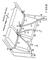
- Fig. 1 is a perspective view illustrating a seat apparatus for a vehicle, according to an embodiment
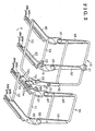
- Fig. 2 is a perspective view illustrating a framework of the seat apparatus for the vehicle, according to the first embodiment
- Fig. 3 is a front view illustrating the framework of the seat apparatus for the vehicle, according to the first embodiment
- Fig. 4 is a planar view illustrating a part of the framework of the seat apparatus for the vehicle, according to the first embodiment
- Fig. 5 is a perspective view illustrating a part of the framework of the seat apparatus for the vehicle, according to the second embodiment.
- Fig. 6 is a side view illustrating a part of the framework of the seat apparatus for the vehicle, according to the second embodiment.
- a double seat (a seat for accommodating two occupants) and a single seat 30 (a seat for accommodating one occupant) are mounted on a vehicle floor F so as to adjoin each other in a width direction (a lateral direction) of the vehicle.
- the double seat 10 serving as a second seat
- the single seat 30 serving as a first seat
- the double seat 10 serving as a second seat
- the single seat 30 serving as a first seat
- the double seat 10 is disposed on a right side space in the vehicle compartment, for example.
- the double seat 10 includes a seat cushion 11, which structures a seating surface, and a seatback 12, which is pivotably supported at a rear end portion of the seat cushion 11.
- the single seat 30 is disposed at a left side space in the vehicle compartment, for example.
- the single seat 30 includes a seat cushion 31 and a seatback 32.
- Three-point supporting seatbelts 13 and 14 are assembled onto the double seat 10 at seating positions thereof, respectively, and a three-point supporting seatbelt 33 is assembled onto the single seat 30 at a seating position thereof. More specifically, the three-point supporting seatbelt 13 is provided at a right side seating position of the double seat 10, i.e., a seating position being opposite from the single seat 30 (serving as a second seating position). Hereinafter, the right side seating position of the double seat 10 is referred to as a right seating position Sr.
- the three-point supporting seatbelt 13 includes a shoulder belt guide member 16, a lap belt anchor 18 and a belt buckle plate 19. The shoulder belt guide member 16 is provided at a right upper side portion of a vehicle body B.
- a shoulder belt 15 is configured to be unwound from the shoulder belt guide member 16 by being guided thereby.
- the lap belt anchor 18 is provided at a right lower side portion of the vehicle body B.
- a first end portion of a lap belt 17 is fixed to the lap belt anchor 18.
- the belt buckle plate 19 is provided at a laterally intermediate portion of the seat cushion 11.
- An end portion of the shoulder belt 15 unwound from the shoulder belt guide member 16 and a second end portion of the lap belt 17 are configured to be fixed to the belt buckle plate 19.
- the end portion of the shoulder belt 15 and the second end portion of the lap belt 17 are separated by a first tang member.
- the end portion of the shoulder belt 15 and the second end portion of the lap belt 17 are fixed to the belt buckle plate 19.
- the shoulder belt 15 is guided by the shoulder belt guide member 16 and is wound to a winding device, such as an ELR (Emergency Locking Retraction), which is incorporated in the vehicle body B, for example.
- ELR Electronic Land Locking Retraction
- the three-point supporting seatbelt 14 (serving as a seatbelt mechanism) is provided at a left side seating position of the double seat 10, i.e., a seating position being adjacent to the single seat 30 (serving as a third seating position located between a first seating position the second seating position).
- the left side seating position of the double seat 10 is referred to as an intermediate seating position Sc.
- the three-point supporting seatbelt 14 includes a shoulder belt guide member 21, a belt buckle plate (serving as a belt anchor) 23 and a belt buckle plate (serving as a belt attachment portion) 24.
- the shoulder belt guide member 21 is provided at a laterally intermediate portion of an upper portion of the seatback 12.
- a shoulder belt 20 is configured to be unwound from the shoulder belt guide member 21 by being guided thereby.
- the belt buckle plate 23 is provided at the laterally intermediate portion of the seat cushion 11.
- a first end portion of a lap belt 22 is fixedly connected to,the belt buckle plate 23.
- the belt buckle plate 24 is provided at the left side of the seat cushion 11, i.e., at a side portion of the double seat 10 being adjacent to the single seat 30 (serving as a first side portion of the second seat).
- An end portion of the shoulder belt 20 and a second end portion of the lap belt 22 are configured to be fixed to the belt buckle plate 24.
- a second tang member is provided at the first end portion of the lap belt 22 and is configured to be inserted into a buckle of the belt buckle plate 23, thereby fixedly connecting the first end of the lap belt 22 to the belt buckle plate 23. Further, the end portion of the shoulder belt 20 and a second end portion of the lap belt 22 are separated by a third tang member. When the third tang member is inserted into a buckle of the belt buckle plate 24, the end portion of the shoulder belt 20 and the second end portion of the lap belt 22 are fixedly connected to the belt buckle plate 24.
- the shoulder belt 20 is guided by the shoulder belt guide member 21 and is wound to a winding device, such as the ELR.
- the three-point supporting seatbelt 33 provided at the seating position of the single seat (serving as the first seating position of the first seat) 39 includes a shoulder belt guide member 36, a lap belt anchor 38 and a belt buckle plate 39.
- the shoulder belt guide member 36 is provided at a left upper side portion of the vehicle body B.
- a shoulder belt 35 is configured to be unwound from the shoulder belt guide 36 by being guided thereby.
- the lap belt anchor 38 is provided at a left lower side portion of the vehicle body B.
- a first end portion of a lap belt 37 is fixed to the lap belt anchor 38.
- the belt buckle plate 39 is provided at a right side portion of the seat cushion 31, i.e., at a side portion adjacent to the double seat 10 (serving as a first side portion of the first seat).
- An end portion of the shoulder belt 35 and a second end portion of the lap belt 37 are configured to be fixed to the belt buckle plate 39.
- the end portion of the shoulder belt 35 and the second end portion of the lap belt 37 are separated by a fourth tang member.
- the fourth tang member is inserted into a buckle of the belt buckle plate 39, the end portion of the shoulder belt 35 and the second end portion of the lap belt 37 are fixedly connected to the belt buckle plate 37.
- the shoulder belt 35 is guided by the shoulder belt guide member 36 and is wound to a winding device, such as the ELR, which is incorporated in the vehicle body B, for example.
- the double seat 10 includes a side bracket 41, a side frame 42 and a center frame 43.
- Each of the side bracket 41 and the side frame 42 is made from a plate member.
- the side bracket 41 is provided at the side portion of the double seat 10 at a side being adjacent to the single seat 30 (serving as the first side portion of the second seat), i.e., according to the embodiment, the left side portion, for example.
- the side frame 42 is provided at a side portion of the double seat 10 at a side being opposite from the single seat 30 (serving as a second side portion of the second seat), i.e., according to the embodiment, the right side portion, for example.
- the center frame 43 is made from a plate member.
- the center frame 43 is provided at the laterally intermediate portion of the double seat 10.
- the center frame 43 serves as a first frame member
- the side bracket 41 serves as a second frame member.
- a first lower rail 44a and a second lower rail 44b are mounted on the vehicle floor F so as to face the center frame 43 and the side frame 42, respectively.
- Each of the first and second lower rails 44a and 44b includes a U-shaped cross-section, which opens towards an upper side thereof
- a first upper rail 45a and a second upper rail 45b are assembled onto the first and second lower rails 44a and 44b, respectively, so as to be slidable in the forward and backward direction of the vehicle relative to the corresponding lower rails 44a and 44b.
- Each of the first and second upper rails 45a and 45b includes a U-shaped cross-section, which opens towards a lower side thereof.
- the first lower rail 44a and the first upper rail 45a structure a first seat slide mechanism 46a
- the second lower rail 44b and the second upper rail 45b structure a second seat slide mechanism 46b, for forwardly and backwardly moving the double seat 10.
- the side frame 42 and the center frame 43 i.e., the double seat 10) are supported on the vehicle floor F via the first and second seat slide mechanisms 46a and 46b extending in the longitudinal direction of the vehicle.
- a seatback side frame 48 which is made from a plate member, is pivotably connected to a rear end portion of the side frame 42 via a reclining mechanism 47 for adjusting a reclining angle of a seatback of the double seat 10.
- a seatback center frame 50 made from a plate member is pivotably connected to a rear end portion of the center frame 43 via a reclining apparatus 49 serving as the seatback reclining angle adjusting mechanism.
- a seatback side bracket 52 made from a plate member is pivotably connected to a rear end portion of the side bracket 41.
- the side bracket 41, the side frame 42 and the center frame 43 structure a framework of the seat cushion 11, and the seatback side frame 48, the seatback center frame 50 and the seatback side bracket 52 structure a framework of the seatback 12.
- the belt buckle plates 19 and 23 are disposed at the rear end portion of the center frame 43, and the shoulder belt guide member 21 is disposed at an upper end portion of the seatback center frame 50.
- the center frame 43, the first seat slide mechanism 46a supporting the center frame 43, and the reclining apparatus 49 are disposed on a vertical plane on which the shoulder belt guide member 21 and the belt buckle plate 23 are disposed (i.e., those components are arranged to be coplanar in the vertical direction).
- the belt buckle plate 24 is disposed at the rear end portion of the side bracket 41.
- the rear end portion of the side bracket 41 and the rear end portion of the side frame 42 are connected with each other via a rear cross member 54, which is a cylindrical member extending in the lateral direction of the seat between the side frame 42 and the center frame 43 and is arranged to penetrate through the center frame 43.
- a front end portion of the side frame 42 and a front end portion of the center frame 43 are connected with each other via a front cross member 55, which is a cylindrical member extending in the lateral direction of the seat.
- a left end portion of the front cross member 55 (i.e., an end portion being adjacent to the single seat 30) is bent in the backward direction and is connected to a front end portion of the side bracket 41.
- the single seat 30 includes a pair of side frames 61 and 62, which are made from a plate member.
- the side frame 61 is provided at a side portion being adjacent to the double seat 10 (serving as the first side portion of the first seat), i.e., according to the embodiment, at the right side portion of the single seat 30, for example.
- the side frame 62 is provided at a side portion being opposite from the double seat 10 (serving as a second side portion of the first seat), i.e., according to the embodiment, at the left portion of the single seat 30, for example.
- a third lower rail 64a and a fourth lower rail 64b are mounted on the vehicle floor F so as to face the side frames 61 and 62, respectively.
- Each of the third and fourth lower rails 64a and 64b includes a U-shaped cross section which opens towards an upper side thereof. Further, a third upper rail 65a and a fourth upper rail 65b are provided at lower end portions of the side frames 61 and 62, respectively. The third and fourth upper rails 65a and 65b are assembled onto the third and fourth lower rails 64a and 64b, respectively, so as to be slidable in the forward and backward direction of the vehicle relative to the corresponding lower rails 64a and 64b.
- the third lower rail 64a and the third upper rail 65a structure a third seat slide mechanism 66a (serving as a supporting member for supporting the first seat), while the fourth lower rail 64b and the fourth upper rail 65b structure a fourth seat slide mechanism 66b, for forwardly and backwardly moving the single seat 30. Accordingly, the side frames 61 and 62 (i.e., the single seat 30) are supported on the vehicle floor F via the third and fourth seat slide mechanisms 66a and 66b.
- a seatback side frame 69 made from a plate member is pivotably connected to the side frame 61 via a reclining apparatus 67
- a seatback side frame 70 made from a plate member is pivotably connected to the side frame 62 via a reclining apparatus 68.
- the side frames 61 and 62 structure a framework of the seat cushion 31, and the seatback side frame 69 and 70 structure a framework of the seatback 32.
- the belt buckle plate 39 is disposed at a rear end portion of the side frame 61.
- the rear end portion of the side frame 61 and a rear end portion of the side frame 62 are connected with each other via a rear cross member 71, which is a cylindrical member extending in the lateral direction of the seat.
- a front end portion of the side frame 61 and a front end portion of the side frame 62 are connected with each other via a front cross member 72, which is a cylindrical member extending in the lateral direction of the seat.
- An upper hook 73 made from a plate member is fixedly connected to the side bracket 41 of the double seat 10 so as to face the single seat 30.
- the upper hook 73 serves as a first lock member and also as a first hook.
- the upper hook 73 extends in the forward and backward direction of the vehicle and includes a hook portion 73a.
- the hook portion 73a protrudes from the side bracket 41 in the lower direction and includes a U-shaped cross section, which opens towards an upper side thereof.
- a lower hook 74 made from a plate member is fixedly provided at the third lower rail 64a (the third seat slide mechanism 66a), which is provided adjacently to the side bracket 41 of the double seat 10, i.e., according to the embodiment, the right lower rail, so as to face the double seat 10.
- the third lower rail 64a (the third seat slide mechanism 66a) serves as a supporting member for supporting the side frame 61 provided adjacently to the side bracket 41 of the double seat 10.
- the lower hook 74 serves as a second lock member and also as a second hook. As illustrated in Figs.
- the lower hook 74 includes an attachment portion 74a, which includes a plane plate disposed between the vehicle floor F and the third lower rail 64, and a hook portion 74b, which protrudes from the attachment portion 74a in the upper direction and includes a U-shaped cross section opening towards a lower side thereof.
- the upper hook 73 and the lower hook 74 structure the lock mechanism.
- the upper hook 73 and the lower hook 74 allow a relative movement (the movement in the forward and backward direction) between the side bracket 41 of the double seat 10 and the side frame 61 of the single seat 30 without interacting the side bracket 41 and the side frame 61.
- seatbelt load when a collision of the vehicle occurs, for example, the upper hook 73 and the lower hook 74 (the hook portions 73 a and 74b) are engaged with each other, thereby locking the side bracket 41 of the double seat 10 to the third lower rail 64a (vehicle floor F).
- the first seat slide mechanism 46a which is provided adjacently to the single seat 30 for supporting the center frame 43
- the third seat slide mechanism 66a which is provided adjacently to the double seat 10 for supporting the side frame 61
- the center frame 43 of the double seat 10 and the side frame 61 of the single seat 30 are symmetrically arranged relative to the center line L.
- the seatbelt load which is applied to the vehicle floor F at the position corresponding to center frame 43 (i.e., the load applied to the first seat slide mechanism 46a) is inputted from an end of the shoulder belt guide member 21 of the three-point supporting seatbelt 14 provided at the intermediate seating position Sc, an end of the lap belt 22 of the three-point seatbelt 14, an end of the shoulder belt 15 of the three-point supporting seatbelt 13 provided at the right seating position Sr and an end of the lap belt 17 of the three-point supporting seatbelt 13.
- the seatbelt load which is applied to the vehicle floor F at the position corresponding to the side frame 61 (i.e., the load applied to the third seat slide mechanism 66a) is inputted from an end of the shoulder belt 20 of the three-point supporting seatbelt 14, an end of the lap belt 22 of the three-point supporting seatbelt 14, an end of the shoulder belt 35 of the three-point supporting seatbelt 33 and an end of the lap belt 37 of the three-point supporting seatbelt 33.
- the number of input portions of the seatbelt load applied to the first seat slide mechanism 46a (to the vehicle floor F at the position corresponding to the center frame 43) is determined to be equal to the number of input portions of the seatbelt load applied to the third seat slide mechanism 66a (to the vehicle floor F at the position corresponding to the side frame 61). Accordingly, the magnitude of the seatbelt load transmitted to the vehicle floor F at the position corresponding to the center frame 43 and the magnitude of the seatbelt load transmitted to the vehicle floor F at the position corresponding to the side frame 61 are arranged to be approximately the same.
- the double seat 10 includes the lock mechanism (the upper hook 73 and the lower hook 74) between the side bracket 41 and the vehicle floor F
- the lock mechanism includes a simple structure which does not interact with the side bracket 41.
- a part of a space for disposing the third seat slide mechanism 66a of the single seat 30 is employed for disposing the lock mechanism. Therefore, a space required for disposing the lock mechanism may be reduced.
- the double seat 10 includes two seat slide mechanisms (first and second seat slide mechanisms 46a and 46b). Therefore, an increase of the weight of the seat apparatus is suppressed, and a structure of the seat apparatus is simplified.
- the seatbelt load generated when the collision of the vehicle occurs is received by the upper hook 73 and the lower hook 74 in addition to the first and second seat slide mechanisms 46a and 46b. Accordingly, a satisfactory strength (resistibility) of the seat apparatus is assured.
- the double seat 10 is restrained from being forced to be separated from the vehicle floor F, and the deformation of the double seat 10 is restrained.
- the lower hook 74 is provided at the third lower rail 64a, which structures the third seat slide mechanism 66a being adjacent to the side bracket 41.
- a space for the third seat slide mechanism 66a is effectively used as a space for disposing the lower hook 74.
- a position of the upper hook 73 and the lower hook 74, each of which extends in the forward and backward direction of the vehicle, may be determined in accordance with a longitudinal range of the side bracket 41 or a longitudinal range of the third seat slide mechanism 66a provided adjacently to the side bracket 41 of the double seat 10. Accordingly, the upper hook 73 and the lower hook 74 are restrained from exposing to an external portion of the seat apparatus, thereby improving an external appearance of the seat apparatus. Further, each of the upper hook 73 and the lower hook 74 is easily formed by bending the plate member, for example.
- the center frame 43 of the double seat 10 and the side frame 61 of the single seat 30 are arranged symmetrically relative to the center line L. Further, the number of input portions of the seatbelt load applied to the first seat slide mechanism 46a (to the vehicle floor F at the position corresponding to the center frame 43) is determined to be equal to the number of input portions of the seatbelt load applied to the third seat slide mechanism 66a (to the vehicle floor F at the position corresponding to the side frame 61). Accordingly, the magnitude of the seatbelt load transmitted to the vehicle floor F at the position corresponding to the center frame 43 and the magnitude of the seatbelt load transmitted to the vehicle floor F at the position corresponding to the side frame 61 are arranged to be approximately the same. Therefore, the vehicle floor F is deformed equally in the lateral direction when the collision of the vehicle occurs, for example.
- the double seat 10 includes two seat slide mechanisms (first and second seat slide mechanisms 46a and 46b). Therefore, a space between the side bracket 41 and the center frame 43 is substantially opened. Accordingly, a sufficient foot space of an occupant seated on a backside seat disposed at a backside of the double seat 10 is obtained, and a restriction of a seating attitude of the occupant seated on the backside seat is reduced.
- a second embodiment of the present invention will be described hereinbelow with reference to the attached drawings.
- a lock mechanism which includes a different structure from the structure of the lock mechanism (the upper hook 73 and the lower hook 74) according to the first embodiment, is employed.
- the description of portions having the same structure will be omitted herein.
- the belt buckle plate 24 provided at the side bracket 41 of the double seat 10 includes a supporting point 81 (serving as a pivot center) at which the belt buckle plate 24 is supported to the side bracket 41, and an extending portion 82, which extends from the supporting point 81 in the lower direction.
- the belt.buckle plate 24 includes a guide member 83, which is formed at an end portion of the extending portion.
- the guide member 83 (serving as a first lock member) is formed in a quadrate hollow member extending in the forward and backward direction of the vehicle. Further, as illustrated in Figs.
- a quadrate hollow member 84 (serving as a hollow portion) is housed in the guide member 83 at an intermediate portion thereof in the height direction.
- the quadrate hollow member 84 extends in the forward and backward direction of the vehicle and is made of a resin material, for example.
- a ball member 85 (serving as a locking portion) is retained in the guide member 83 at a lower side of the hollow member 84, i.e., between a lower side surface of the quadrate hollow member 84 and an inner surface of a base wall of the guide member 83.
- an L-shaped bracket 91 is fixedly provided at a rear end portion of the third lower rail 64a of the third seat slide mechanism 66a, which supports the side frame 61 being adjacent to the side bracket 41 of the double seat 10.
- the bracket 91 includes a first attachment portion 91a, which is a plane plate member provided between the vehicle floor F and the third lower rail 64a, and a second attachment portion 91b, which extends upwardly from the first attachment portion 91a.
- the bracket 91 is fixed to the vehicle floor F at the rear end portion of the third lower rail 64a by a connecting member, for example. Accordingly, the third lower rail 64a and the bracket 91 are fixedly integrally connected to each other.
- a supporting lever 93 (serving as a lever member) is pivotably connected to the second attachment portion 91b of the bracket 91 about a supporting pivot shaft 92.
- the supporting lever 93 extends in the front direction from a position at which the supporting pivot shaft 92 is connected. Further, the supporting lever 93 is inserted through the quadrate hollow member 84 of the guide member 83.
- Plural locking teeth (serving as a plurality of locking protrusions) 93a are longitudinally equidistantly formed at a lower side portion of the supporting lever 93 exhibiting a saw blade shape.
- the ball member 85 is disposed to face one of the locking teeth 93a in accordance with a position of the double seat 10 in the forward and backward direction of the vehicle.
- the hollow member 84 is deformed (crushed) between one of the locking teeth 93a and the ball member 85 and the one of the locking teeth 93a and the ball member 85 are engaged with each other (more specifically, the ball member 85 is lodged between two of the locking teeth 93a), thereby locking the side bracket 41 (the double seat 10) relative to the vehicle floor F.
- the supporting lever 93 and the guide member 83 which structures the locking mechanism, includes a saber mechanism.
- the hollow member 84 is deformed between one of the locking teeth 93a and the ball member 85, and the one of the locking teeth 93a and the ball member 85 are engaged with each other, thereby locking the side bracket 41 (the double seat 10) to the vehicle floor F.
- the supporting lever 93 which is engaged with the guide member 83 when the collision of the vehicle occurs, is supported by the vehicle floor F at the pivot center defined adjacently to the vehicle floor F, regardless of the longitudinal position of the seat 10. Accordingly, the seatbelt load generated when the collision of the vehicle occurs is effectively received by the vehicle floor F.
- the ball member 85 when the normal seatbelt load is applied to the double seat 10, the ball member 85 is prevented from being engaged with one of the locking teeth 93a by being interrupted by the hollow member 84. Accordingly, the longitudinal position of the double seat 10 is smoothly adjusted. Further, a load for deforming (crushing) the hollow member 84 of the guide member 83 is appropriately determined. Accordingly, a load generated against the seatbelt load for locking the side bracket 41 (the double seat 10) and the vehicle floor F is effectively controlled.
- the upper hook 73 may be formed at the side bracket 41 so as to be integral therewith.
- the lower hook 74 may be fixedly connected to the vehicle floor F in the vicinity of the third lower rail 64a.
- the supporting lever 93 may be pivotably connected to the vehicle floor F in the vicinity of the rear end portion of the third lower rail 64a. In such conditions, the vehicle floor F around the single seat 30 serves as a supporting member for supporting the single seat 30 (the first seat).
- a locking tooth or plural locking teeth may be provided in place of the ball member 85 so as to be engageable with the locking teeth 93a of the supporting lever 93.
- a locking hole or plural locking holes, into which the locking teeth 93a is inserted, may be provided at the guide member 83.
- the side bracket 41 and the side frame 42 may be formed to be symmetrical to each other.
- the three-point supporting seatbelts 13, 14 and 33 may be structured in a manner where each of the shoulder belts 15, 20, 35 and each of the lap belts 17, 22, 37 are connected by a metallic connecting member as an example.
- the seat apparatus for the vehicle includes the single seat 30 (the first seat), the double seat 10 (the second seat), and the three-point supporting seatbelt 14 (the seatbelt mechanism).
- the single seat is adapted to be mounted on the vehicle floor F and includes the seating position Sl (the first seating position).
- the double seat 10 is also adapted to be mounted on the vehicle floor F via the first and second seat slide mechanisms 46a and 46b extending in the longitudinal direction of the vehicle so as to adjoin the single seat 30 in the width direction of the vehicle.
- the double seat 10 includes the seating position Sr (the second seating position) and the seating position Sc (the third seating position) between the seating positions Sr and Sc.
- the three-point supporting seatbelt 14 is provided at the seating position Sc of the double seat 10.
- the three-point supporting seatbelt 14 includes the shoulder belt guide member 21 for guiding the shoulder belt 20, the belt buckle plate 23 (the belt anchor) to which the first end portion of the lap belt 22 is fixedly connected, and the belt buckle plate 24 (the belt attachment portion) which is provided at the first side portion of the double seat 10 and to which the first end portion of the shoulder belt 20 and the second end portion of the lap belt 22 are configured to be fixedly connected.
- the center frame 43 (the first frame member) for supporting the double seat 10 and the first seat slide mechanism 46a are arranged to be vertically coplanar with the shoulder belt guide member 21 and the belt buckle plate 23.
- the second seat slide mechanism 46b is disposed at the second side portion of the double seat 10.
- the side bracket 41 (the second frame member) for supporting the double seat 10 is disposed at the first side portion of the double seat 10.
- the first lock member (the upper hook 73, the guide member 83) is provided at the side bracket 41 of the double seat 10.
- the second lock member (the lower hook 74, the supporting lever 93) is provided at the supporting member (the third seat slide mechanism 66a, the vehicle floor F around the third seat slide mechanism 66s).
- the first and second lock members allow a movement of the side bracket 41 (the double seat 10) relative to the vehicle floor F when the excess load is received from the three-point supporting seatbelt 14.
- the double seat 10 includes the lock mechanism (the upper hook 73 and the lower hook 74 or the guide member 83 including the locking ball 85 and the supporting lever 93) between the side bracket 41 and the supporting member for supporting the single seat 30 (the third seat slide mechanism 66a or the vehicle floor F), the lock mechanism includes a simple structure which does not interact with the side bracket 41. Further, a part of the space for disposing the supporting member (the third seat slide mechanism 66a or the vehicle floor F around the single seat 30) is employed for disposing the lock mechanism. Therefore, a space required for disposing the lock mechanism may be reduced. Further, the double seat 10 includes two seat slide mechanisms (first and second seat slide mechanisms 46a and 46b).
- the seatbelt load generated when the collision of the vehicle occurs is received by the first and second lock members (the upper hook 73 and the lower hook 74 or the guide member 83 and the supporting lever 93) in addition to the first and second seat slide mechanisms 46a and 46b. Accordingly, a satisfactory strength (resistibility) of the seat apparatus is assured.
- the first lock member includes the upper hook 73 (the first hook), which extends in the forward and backward direction of the vehicle and includes a U-shaped cross section opening towards the upper side thereof.
- the second lock member includes the lower hook 74 (the second hook), which extends in the forward and backward direction of the vehicle at a position further upwardly than the upper hook 73 and includes a U-shaped cross section opening towards the lower side thereof.
- the side bracket 41 is locked relative to the vehicle floor F by the engagement between the upper and lower hooks 73 and 74 when the excess load is received through the three-point supporting seatbelt 14.
- the position of the upper and lower hooks 73 and 74 may be determined in accordance with the longitudinal range of the side bracket 41 or the longitudinal range of the supporting member provided adjacently to the side bracket 41 of the double seat 10. Accordingly, the upper and lower hooks 73 and 74 are restrained from exposing to the external portion of the seat apparatus, thereby improving the external appearance of the seat apparatus.
- the first lock member includes the guide member 83 which extends from the belt buckle plate 24 provided at the side bracket 41 of the double seat 10 and includes the ball member 85 (the locking portion).
- the second lock member includes the supporting lever 93 (the lever member) which includes the plural locking teeth 93a (the plural locking protrusions) equidistantly aligned in the forward and backward direction of the vehicle so as to be engageable with the ball member 85 of the guide member 83.
- the side bracket 41 is locked relative to the vehicle floor F by the engagement between the one of the locking teeth 93a of the supporting lever 93 and the ball member 85 of the guide member 83 when the excess load is received through the three-point supporting seatbelt.
- the supporting lever 93 which is engaged with the guide member 83 when the collision of the vehicle occurs, for example, is supported by the vehicle floor F at the pivot center 92 defined adjacently to the vehicle floor F, regardless of the longitudinal position of double seat 10. Accordingly, the seatbelt load generated when the collision of the vehicle occurs is effectively received by the vehicle floor F.
- the guide member 83 includes the hollow member 84 (the hollow portion) through which the supporting lever 93 is inserted.
- the ball member 85 of the guide member 83 is provided at the lower side of the hollow member 84.
- the locking teeth 93a are formed at the lower side portion of the supporting lever 93.
- the ball member 85 is prevented from being engaged with one of the locking teeth 93a by being interrupted by the hollow member 84. Accordingly, the longitudinal position of the double seat 10 is smoothly adjusted. Further, the load for deforming (crushing) the hollow member 84 of the guide member 83 is appropriately determined. Accordingly, a load generated against the load for locking the side bracket 41 (the double seat 10) and the vehicle floor F is effectively controlled.
- the supporting member includes the third seat slide mechanism 66a for supporting the single seat 30.
- the number of input portions of the load applied to the first seat slide mechanism 46a and 46b is determined to be equal to the number of input portions of the load applied to the third seat slide mechanism 66a when the excess load is received through the three-point supporting seatbelt 14.
- first seat slide mechanism 46a and the third seat slide mechanism 66a are disposed symmetrically relative to the enter line L of the vehicle floor F in the width direction of the vehicle.
- the seatbelt load applied to the vehicle floor F at the position corresponding to center frame 43 (the load applied to the first seat slide mechanism 46a) is inputted from an end of the shoulder belt guide member 21 of the three-point supporting seatbelt 14 provided at the intermediate seating position Sc, an end of the lap belt 22 of the three-point seatbelt 14, an end of the shoulder belt 15 of the three-point supporting seatbelt 13 provided at the right seating position Sr and an end of the lap belt 17 of the three-point supporting seatbelt 13.
- the seatbelt load applied to the vehicle floor F at the position corresponding to the side frame 61 (the load applied to the third seat slide mechanism 66a) is inputted from an end of the shoulder belt 20of the three-point supporting seatbelt 14, an end of the lap belt 22 of the three-point supporting seatbelt 14, an end of the shoulder belt 35 of the three-point supporting seatbelt 33 and an end of the lap belt 37 of the three-point supporting seatbelt 33.
- the number of input portions of the seatbelt load applied to the first seat slide mechanism 46a is determined to be equal to the number of input portions of the seatbelt load applied to the third seat slide mechanism 66a.
- a seat apparatus for a vehicle includes a first seat (30), a second seat (10), and a seatbelt mechanism (14) provided at the second seat (10).
- a first frame member (43) for supporting the second seat (10) and a first seat slide mechanism (46a) for slidably moving the second seat (10) are arranged to be vertically coplanar with a shoulder belt guide member (21) and the belt anchor (23) of the seatbelt mechanism (14).
- a first lock member (73, 83) is provided at a second frame member (41) disposed adjacently to the first seat (30) for supporting the second seat (10).
- a second lock member (74, 93) is provided at a supporting member (F, 66a) for supporting the first seat (30).
- the first and second lock members (73, 74, 83, 93) allow a movement of the second frame member (41) in a forward and backward direction of the vehicle and engage with each other for locking the second frame member (41) relative to a vehicle floor (F) when an excess load is received from the seatbelt mechanism
Landscapes
- Engineering & Computer Science (AREA)
- Mechanical Engineering (AREA)
- Aviation & Aerospace Engineering (AREA)
- Transportation (AREA)
- Seats For Vehicles (AREA)
- Automotive Seat Belt Assembly (AREA)
Abstract
Description
- The present invention generally relates to a seat apparatus for a vehicle.
- As an example of a seat apparatus for a vehicle including a double seat (a seat including two seating positions for accommodating two occupants) and a single seat (a seat including one seating position for accommodating one occupant) which adjoin each other in a width direction of the vehicle, a seat apparatus disclosed in
DE103 11 869A1 (hereinafter, referred to as reference 1) has been known. According to the reference 1, the double seat is structured so that a three-point supporting seatbelt is assembled thereon for each seating position. Accordingly, a shoulder belt guide member (through anchor) for guiding a shoulder belt and a belt anchor of the three-point supporting seatbelt are provided at an approximately intermediate portion of the double seat in the width direction (lateral direction) of the vehicle. Further, seat slide mechanisms for adjusting a position in a front-rear direction of the vehicle is provided at lateral sides of the double seat, respectively. Still further, a seatback reclining mechanism (recliner) for adjusting a reclining angle of a seatback and an auxiliary seat slide mechanism which is movable in the front-rear direction of the vehicle are provided at the laterally intermediate portion of the double seat, at which the belt anchor and the shoulder belt guide member are also provided. The auxiliary seat slide mechanism functions as a reinforcement member and receives a separating load and a bending moment, i.e., a load generated by the shoulder belt anchor provided at the laterally intermediate portion of the double seat and a load generated by the lap belt anchor provided at the laterally intermediate portion of the double seat, when a collision of the vehicle occurs, for example. Thus, the seat is suppressed from separating from a vehicle floor. - A double seat including such structure is also disclosed in
JP 2002-337576A JP2002-347497A - According to the reference 1, the double seat includes three seat slide mechanisms (the seat slide mechanisms disposed at the lateral sides of the double seat and the auxiliary seat slide mechanism), which extend in the front-rear direction of the vehicle while having a distance from each other in the lateral direction. Accordingly, the weight of the seat apparatus is increased, and also the structure of the seat apparatus becomes complicated. Further, because the three seat slide mechanisms occupy a floor space defined at a back side of the double seat, i.e., a foot space of an occupant seated on a backside seat disposed at a backside of the double seat, a seating attitude of the occupant seated on the backside seat may be restrained.
- A need thus exists for a seat apparatus for a vehicle including a double seat and a single seat adjoining each other in a width direction of the vehicle, which suppresses an increase of a weight of the seat apparatus and which includes a simple structure.
- According to an aspect of the present invention, a seat apparatus for a vehicle includes a first seat, a second seat and a seatbelt mechanism. The first seat is adapted to be mounted on a vehicle floor and includes a first seating position. The second seat is adapted to be mounted on the vehicle floor via a first seat slide mechanism and a second seat slide mechanism extending in a forward and backward direction of the vehicle so as to adjoin the first seat in a width direction of the vehicle. The second seat includes a second seating position and a third seating position located between the first seating position and the second seating position. The seatbelt mechanism is provided at the third seating position of the second seat and includes a shoulder belt guide member for guiding a shoulder belt, a belt anchor to which a first end portion of a lap belt is fixedly connected, and a belt attachment portion which is provided at a first side portion of the second seat being adjacent to the first seat and to which a first end portion of the shoulder belt and a second end portion of the lap belt are configured to be fixedly connected. A first frame member for supporting the second seat and the first seat slide mechanism are arranged to be vertically coplanar with the shoulder belt guide member and the belt anchor. The second seat slide mechanism is disposed at a second side portion of the second seat being opposite from the first seat. A second frame member for supporting the second seat is disposed at the first side portion of the second seat. A first lock member is provided at the second frame member of the second seat. A second lock member is provided at a supporting member for supporting the first seat. The first and second lock members allow a movement of the second frame member in the forward and backward direction of the vehicle and engage with each other for locking the second frame member relative to the vehicle floor when an excess load is received from the seatbelt mechanism.
- Due to the above described structure, although the second seat includes the first and second lock members between the second frame member and the supporting member for supporting the first seat, a lock mechanism structured with the first and second lock members includes a simple structure which does not interact with the second frame member. Further, a part of a space for disposing the supporting member of the first seat is employed for disposing the lock mechanism. Therefore, a space required for disposing the lock mechanism may be reduced. Further, the second seat includes two seat slide mechanisms (first and second seat slide mechanisms). Therefore, an increase of the weight of the seat apparatus is suppressed, and a structure of the seat apparatus is simplified. Further, the load generated when a collision of the vehicle occurs, for example, is received by the first and second lock members in addition to the first and second seat slide mechanisms. Accordingly, a satisfactory strength (resistibility) of the seat apparatus is assured.
- Further, the first lock member includes a first hook extending in the forward and backward direction of the vehicle and having a U-shaped cross section opening towards an upper side thereof. The second lock member includes a second hook extending in the forward and backward direction of the vehicle at a position further upwardly than the first hook and having a U-shaped cross section opening towards a lower side thereof. The second frame member is locked relative to the vehicle floor by an engagement between the first and second hooks when the excess load is received through the seatbelt mechanism.
- Due to the above described structure, a position of the first hook and second hook, each of which extends in the forward and backward direction of the vehicle, may be determined in accordance with a longitudinal range of the second frame member or a longitudinal range of the supporting member provided adjacently to the second frame member of the second seat. Accordingly, the first and second hooks are restrained from exposing to an external portion of the seat apparatus, thereby improving an external appearance of the seat apparatus.
- Still further, the first lock member includes a guide member extending from the belt attachment portion provided at the second frame member and having a locking portion. The second lock member includes a lever member pivotably connected to the supporting member and extending in the forward and backward direction of the vehicle and inserted through the guide member. The lever member has a plurality of locking protrusions equidistantly aligned in the forward and backward direction of the vehicle so as to be engageable with the locking portion of the first hook. The second frame member is locked relative to the vehicle floor by an engagement between one of the locking protrusions of the lever member and the locking portion of the guide member when the excess load is received through the seatbelt mechanism.
- Due to the above described structure, the lever member, which is engaged with the guide member when the collision of the vehicle occurs, for example, is supported by the vehicle floor at a pivot center defined adjacently to the vehicle floor, regardless of the longitudinal position of second seat. Accordingly, the load generated when the collision of the vehicle occurs is effectively received by the vehicle floor.
- Still further, the guide member includes a hollow portion through which the lever member is inserted. The locking portion of the guide member is provided at a lower side of the hollow portion. The plurality of locking protrusions are formed at a lower side portion of the lever member. The hollow portion is deformed between one of the locking protrusions and the locking portion and the one of the locking protrusions and the locking portion are engaged with each other for locking the second frame member relative to the vehicle floor when the excess load is received through the seatbelt mechanism.
- Due to the above described structure, when a normal seatbelt load is applied to the second seat, the locking portion is prevented from being engaged with one of the locking protrusions by being interrupted by the hollow portion. Accordingly, the longitudinal position of the second seat is smoothly adjusted. Further, a load for deforming (crushing) the hollow portion of the guide member is appropriately determined. Accordingly, a load generated against the load for locking the second frame member (the second seat) and the vehicle floor is effectively controlled.
- Still further according to another aspect of the present invention, the supporting member includes a third seat slide mechanism for supporting the first seat. The number of input portions of a load applied to the first seat slide mechanism is determined to be equal to the number of input portions of a load applied to the third seat slide mechanism when the excess load is received through the seatbelt mechanism.
- Further, the first seat slide mechanism and the third seat slide mechanism are disposed symmetrically relative to a center line of the vehicle floor in the width direction of the vehicle.
- Due to the above described structure, the magnitude of the seatbelt load transmitted to the first slide mechanism and the magnitude of the seatbelt load transmitted to the third slide mechanism are arranged to be approximately the same. Accordingly, the vehicle floor is deformed equally in the width direction when the collision of the vehicle occurs, for example.
- The foregoing and additional features and characteristics of the present invention will become more apparent from the following detailed description considered with reference to the accompanying drawings, wherein:
-
Fig. 1 is a perspective view illustrating a seat apparatus for a vehicle, according to an embodiment; -
Fig. 2 is a perspective view illustrating a framework of the seat apparatus for the vehicle, according to the first embodiment; -
Fig. 3 is a front view illustrating the framework of the seat apparatus for the vehicle, according to the first embodiment; -
Fig. 4 is a planar view illustrating a part of the framework of the seat apparatus for the vehicle, according to the first embodiment; -
Fig. 5 is a perspective view illustrating a part of the framework of the seat apparatus for the vehicle, according to the second embodiment; and -
Fig. 6 is a side view illustrating a part of the framework of the seat apparatus for the vehicle, according to the second embodiment. - A first embodiment of the present invention will be described hereinbelow with reference to the attached drawings. As illustrated in
Fig. 1 , a double seat (a seat for accommodating two occupants) and a single seat 30 (a seat for accommodating one occupant) are mounted on a vehicle floor F so as to adjoin each other in a width direction (a lateral direction) of the vehicle. The double seat 10 (serving as a second seat) and the single seat 30 (serving as a first seat) are adapted to be positioned on a second row in a vehicle having a three-row seating configuration, as an example. Hereinafter, directions, such as "front and rear (longitudinal)", "right and left (lateral/width direction), "upper and lower (vertical)", and the like, correspond to the orientation of the seats (10 and 30). Thedouble seat 10 is disposed on a right side space in the vehicle compartment, for example. Thedouble seat 10 includes a seat cushion 11, which structures a seating surface, and aseatback 12, which is pivotably supported at a rear end portion of the seat cushion 11. Thesingle seat 30 is disposed at a left side space in the vehicle compartment, for example. In the same manner as thedouble seat 10, thesingle seat 30 includes aseat cushion 31 and aseatback 32. - Three-
point supporting seatbelts double seat 10 at seating positions thereof, respectively, and a three-point supporting seatbelt 33 is assembled onto thesingle seat 30 at a seating position thereof. More specifically, the three-point supporting seatbelt 13 is provided at a right side seating position of thedouble seat 10, i.e., a seating position being opposite from the single seat 30 (serving as a second seating position). Hereinafter, the right side seating position of thedouble seat 10 is referred to as a right seating position Sr. The three-point supporting seatbelt 13 includes a shoulderbelt guide member 16, alap belt anchor 18 and abelt buckle plate 19. The shoulderbelt guide member 16 is provided at a right upper side portion of a vehicle body B.A shoulder belt 15 is configured to be unwound from the shoulderbelt guide member 16 by being guided thereby. Thelap belt anchor 18 is provided at a right lower side portion of the vehicle body B. A first end portion of alap belt 17 is fixed to thelap belt anchor 18. Thebelt buckle plate 19 is provided at a laterally intermediate portion of the seat cushion 11. An end portion of theshoulder belt 15 unwound from the shoulderbelt guide member 16 and a second end portion of thelap belt 17 are configured to be fixed to thebelt buckle plate 19. The end portion of theshoulder belt 15 and the second end portion of thelap belt 17 are separated by a first tang member. When the first tang member is inserted into a buckle of thebelt buckle plate 19, the end portion of theshoulder belt 15 and the second end portion of thelap belt 17 are fixed to thebelt buckle plate 19. Theshoulder belt 15 is guided by the shoulderbelt guide member 16 and is wound to a winding device, such as an ELR (Emergency Locking Retraction), which is incorporated in the vehicle body B, for example. - The three-point supporting seatbelt 14 (serving as a seatbelt mechanism) is provided at a left side seating position of the
double seat 10, i.e., a seating position being adjacent to the single seat 30 (serving as a third seating position located between a first seating position the second seating position). Hereinafter, the left side seating position of thedouble seat 10 is referred to as an intermediate seating position Sc. The three-point supporting seatbelt 14 includes a shoulderbelt guide member 21, a belt buckle plate (serving as a belt anchor) 23 and a belt buckle plate (serving as a belt attachment portion) 24. The shoulderbelt guide member 21 is provided at a laterally intermediate portion of an upper portion of theseatback 12. Ashoulder belt 20 is configured to be unwound from the shoulderbelt guide member 21 by being guided thereby. Thebelt buckle plate 23 is provided at the laterally intermediate portion of the seat cushion 11. A first end portion of alap belt 22 is fixedly connected to,thebelt buckle plate 23. Thebelt buckle plate 24 is provided at the left side of the seat cushion 11, i.e., at a side portion of thedouble seat 10 being adjacent to the single seat 30 (serving as a first side portion of the second seat). An end portion of theshoulder belt 20 and a second end portion of thelap belt 22 are configured to be fixed to thebelt buckle plate 24. A second tang member is provided at the first end portion of thelap belt 22 and is configured to be inserted into a buckle of thebelt buckle plate 23, thereby fixedly connecting the first end of thelap belt 22 to thebelt buckle plate 23. Further, the end portion of theshoulder belt 20 and a second end portion of thelap belt 22 are separated by a third tang member. When the third tang member is inserted into a buckle of thebelt buckle plate 24, the end portion of theshoulder belt 20 and the second end portion of thelap belt 22 are fixedly connected to thebelt buckle plate 24. Theshoulder belt 20 is guided by the shoulderbelt guide member 21 and is wound to a winding device, such as the ELR. - The three-
point supporting seatbelt 33 provided at the seating position of the single seat (serving as the first seating position of the first seat) 39 includes a shoulder belt guide member 36, alap belt anchor 38 and abelt buckle plate 39. The shoulder belt guide member 36 is provided at a left upper side portion of the vehicle body B.A shoulder belt 35 is configured to be unwound from the shoulder belt guide 36 by being guided thereby. Thelap belt anchor 38 is provided at a left lower side portion of the vehicle body B. A first end portion of alap belt 37 is fixed to thelap belt anchor 38. Thebelt buckle plate 39 is provided at a right side portion of theseat cushion 31, i.e., at a side portion adjacent to the double seat 10 (serving as a first side portion of the first seat). An end portion of theshoulder belt 35 and a second end portion of thelap belt 37 are configured to be fixed to thebelt buckle plate 39. The end portion of theshoulder belt 35 and the second end portion of thelap belt 37 are separated by a fourth tang member. When the fourth tang member is inserted into a buckle of thebelt buckle plate 39, the end portion of theshoulder belt 35 and the second end portion of thelap belt 37 are fixedly connected to thebelt buckle plate 37. Theshoulder belt 35 is guided by the shoulder belt guide member 36 and is wound to a winding device, such as the ELR, which is incorporated in the vehicle body B, for example. - As illustrated in
Figs. 2 and3 , thedouble seat 10 includes aside bracket 41, aside frame 42 and acenter frame 43. Each of theside bracket 41 and theside frame 42 is made from a plate member. Theside bracket 41 is provided at the side portion of thedouble seat 10 at a side being adjacent to the single seat 30 (serving as the first side portion of the second seat), i.e., according to the embodiment, the left side portion, for example. Theside frame 42 is provided at a side portion of thedouble seat 10 at a side being opposite from the single seat 30 (serving as a second side portion of the second seat), i.e., according to the embodiment, the right side portion, for example. Thecenter frame 43 is made from a plate member. Thecenter frame 43 is provided at the laterally intermediate portion of thedouble seat 10. Thecenter frame 43 serves as a first frame member, while theside bracket 41 serves as a second frame member. Further, a firstlower rail 44a and a secondlower rail 44b are mounted on the vehicle floor F so as to face thecenter frame 43 and theside frame 42, respectively. Each of the first and secondlower rails upper rail 45a and a secondupper rail 45b are assembled onto the first and secondlower rails lower rails upper rails lower rail 44a and the firstupper rail 45a structure a firstseat slide mechanism 46a, while the secondlower rail 44b and the secondupper rail 45b structure a secondseat slide mechanism 46b, for forwardly and backwardly moving thedouble seat 10. Accordingly, theside frame 42 and the center frame 43 (i.e., the double seat 10) are supported on the vehicle floor F via the first and secondseat slide mechanisms - Further, a
seatback side frame 48, which is made from a plate member, is pivotably connected to a rear end portion of theside frame 42 via areclining mechanism 47 for adjusting a reclining angle of a seatback of thedouble seat 10. Aseatback center frame 50 made from a plate member is pivotably connected to a rear end portion of thecenter frame 43 via areclining apparatus 49 serving as the seatback reclining angle adjusting mechanism. Still further, aseatback side bracket 52 made from a plate member is pivotably connected to a rear end portion of theside bracket 41. Theside bracket 41, theside frame 42 and thecenter frame 43 structure a framework of the seat cushion 11, and theseatback side frame 48, theseatback center frame 50 and theseatback side bracket 52 structure a framework of theseatback 12. Thebelt buckle plates center frame 43, and the shoulderbelt guide member 21 is disposed at an upper end portion of theseatback center frame 50. In other words, thecenter frame 43, the firstseat slide mechanism 46a supporting thecenter frame 43, and thereclining apparatus 49 are disposed on a vertical plane on which the shoulderbelt guide member 21 and thebelt buckle plate 23 are disposed (i.e., those components are arranged to be coplanar in the vertical direction). Further, thebelt buckle plate 24 is disposed at the rear end portion of theside bracket 41. - The rear end portion of the
side bracket 41 and the rear end portion of theside frame 42 are connected with each other via arear cross member 54, which is a cylindrical member extending in the lateral direction of the seat between theside frame 42 and thecenter frame 43 and is arranged to penetrate through thecenter frame 43. Further, a front end portion of theside frame 42 and a front end portion of thecenter frame 43 are connected with each other via afront cross member 55, which is a cylindrical member extending in the lateral direction of the seat. A left end portion of the front cross member 55 (i.e., an end portion being adjacent to the single seat 30) is bent in the backward direction and is connected to a front end portion of theside bracket 41. - The
single seat 30 includes a pair of side frames 61 and 62, which are made from a plate member. Theside frame 61 is provided at a side portion being adjacent to the double seat 10 (serving as the first side portion of the first seat), i.e., according to the embodiment, at the right side portion of thesingle seat 30, for example. Theside frame 62 is provided at a side portion being opposite from the double seat 10 (serving as a second side portion of the first seat), i.e., according to the embodiment, at the left portion of thesingle seat 30, for example. A thirdlower rail 64a and a fourthlower rail 64b are mounted on the vehicle floor F so as to face the side frames 61 and 62, respectively. Each of the third and fourthlower rails upper rail 65a and a fourthupper rail 65b are provided at lower end portions of the side frames 61 and 62, respectively. The third and fourthupper rails lower rails lower rails lower rail 64a and the thirdupper rail 65a structure a thirdseat slide mechanism 66a (serving as a supporting member for supporting the first seat), while the fourthlower rail 64b and the fourthupper rail 65b structure a fourthseat slide mechanism 66b, for forwardly and backwardly moving thesingle seat 30. Accordingly, the side frames 61 and 62 (i.e., the single seat 30) are supported on the vehicle floor F via the third and fourthseat slide mechanisms - Further, a
seatback side frame 69 made from a plate member is pivotably connected to theside frame 61 via areclining apparatus 67, and aseatback side frame 70 made from a plate member is pivotably connected to theside frame 62 via areclining apparatus 68. The side frames 61 and 62 structure a framework of theseat cushion 31, and theseatback side frame seatback 32. Thebelt buckle plate 39 is disposed at a rear end portion of theside frame 61. - The rear end portion of the
side frame 61 and a rear end portion of theside frame 62 are connected with each other via arear cross member 71, which is a cylindrical member extending in the lateral direction of the seat. A front end portion of theside frame 61 and a front end portion of theside frame 62 are connected with each other via afront cross member 72, which is a cylindrical member extending in the lateral direction of the seat. - An
upper hook 73 made from a plate member is fixedly connected to theside bracket 41 of thedouble seat 10 so as to face thesingle seat 30. Theupper hook 73 serves as a first lock member and also as a first hook. Theupper hook 73 extends in the forward and backward direction of the vehicle and includes ahook portion 73a. Thehook portion 73a protrudes from theside bracket 41 in the lower direction and includes a U-shaped cross section, which opens towards an upper side thereof. - On the other hand, a
lower hook 74 made from a plate member is fixedly provided at the thirdlower rail 64a (the thirdseat slide mechanism 66a), which is provided adjacently to theside bracket 41 of thedouble seat 10, i.e., according to the embodiment, the right lower rail, so as to face thedouble seat 10. The thirdlower rail 64a (the thirdseat slide mechanism 66a) serves as a supporting member for supporting theside frame 61 provided adjacently to theside bracket 41 of thedouble seat 10. Thelower hook 74 serves as a second lock member and also as a second hook. As illustrated inFigs. 3 and 4 , thelower hook 74 includes anattachment portion 74a, which includes a plane plate disposed between the vehicle floor F and the third lower rail 64, and ahook portion 74b, which protrudes from theattachment portion 74a in the upper direction and includes a U-shaped cross section opening towards a lower side thereof. Theupper hook 73 and thelower hook 74 structure the lock mechanism. - So configured, a clearance is generated between the
upper hook 73 and the lower hook 74 (thehook portions upper hook 73 and thelower hook 74 are prevented from interfering with each other. In other words, theupper hook 73 and thelower hook 74 allow a relative movement (the movement in the forward and backward direction) between theside bracket 41 of thedouble seat 10 and theside frame 61 of thesingle seat 30 without interacting theside bracket 41 and theside frame 61. Further, in a condition where thedouble seat 10 is forced forwardly due to an excess load received through theseatbelts 13 and 14 (hereinafter, referred to as seatbelt load), when a collision of the vehicle occurs, for example, theupper hook 73 and the lower hook 74 (thehook portions side bracket 41 of thedouble seat 10 to the thirdlower rail 64a (vehicle floor F). - Further, as illustrated in
Fig. 3 , the firstseat slide mechanism 46a, which is provided adjacently to thesingle seat 30 for supporting thecenter frame 43, and the thirdseat slide mechanism 66a, which is provided adjacently to thedouble seat 10 for supporting theside frame 61, are symmetrically arranged relative to a center line defined at an approximately laterally intermediate portion of the vehicle floor F (which is indicated with a symmetric axis L inFig. 3 ). In other words, thecenter frame 43 of thedouble seat 10 and theside frame 61 of thesingle seat 30 are symmetrically arranged relative to the center line L. Further, in the condition where the collision of the vehicle occurs when each of the seating positions Sr, Sc and Sl is occupied, for example, the seatbelt load, which is applied to the vehicle floor F at the position corresponding to center frame 43 (i.e., the load applied to the firstseat slide mechanism 46a) is inputted from an end of the shoulderbelt guide member 21 of the three-point supporting seatbelt 14 provided at the intermediate seating position Sc, an end of thelap belt 22 of the three-point seatbelt 14, an end of theshoulder belt 15 of the three-point supporting seatbelt 13 provided at the right seating position Sr and an end of thelap belt 17 of the three-point supporting seatbelt 13. Further, in the same condition, the seatbelt load, which is applied to the vehicle floor F at the position corresponding to the side frame 61 (i.e., the load applied to the thirdseat slide mechanism 66a) is inputted from an end of theshoulder belt 20 of the three-point supporting seatbelt 14, an end of thelap belt 22 of the three-point supporting seatbelt 14, an end of theshoulder belt 35 of the three-point supporting seatbelt 33 and an end of thelap belt 37 of the three-point supporting seatbelt 33. Thus, the number of input portions of the seatbelt load applied to the firstseat slide mechanism 46a (to the vehicle floor F at the position corresponding to the center frame 43) is determined to be equal to the number of input portions of the seatbelt load applied to the thirdseat slide mechanism 66a (to the vehicle floor F at the position corresponding to the side frame 61). Accordingly, the magnitude of the seatbelt load transmitted to the vehicle floor F at the position corresponding to thecenter frame 43 and the magnitude of the seatbelt load transmitted to the vehicle floor F at the position corresponding to theside frame 61 are arranged to be approximately the same. - According to the embodiment described above, effects described below will be achieved. First, according to the embodiment, although the
double seat 10 includes the lock mechanism (theupper hook 73 and the lower hook 74) between theside bracket 41 and the vehicle floor F, the lock mechanism includes a simple structure which does not interact with theside bracket 41. Further, a part of a space for disposing the thirdseat slide mechanism 66a of thesingle seat 30 is employed for disposing the lock mechanism. Therefore, a space required for disposing the lock mechanism may be reduced. Further, thedouble seat 10 includes two seat slide mechanisms (first and secondseat slide mechanisms upper hook 73 and thelower hook 74 in addition to the first and secondseat slide mechanisms double seat 10 is restrained from being forced to be separated from the vehicle floor F, and the deformation of thedouble seat 10 is restrained. - Second, according to the embodiment, the
lower hook 74 is provided at the thirdlower rail 64a, which structures the thirdseat slide mechanism 66a being adjacent to theside bracket 41. Thus, a space for the thirdseat slide mechanism 66a is effectively used as a space for disposing thelower hook 74. - Third, according to the embodiment, a position of the
upper hook 73 and thelower hook 74, each of which extends in the forward and backward direction of the vehicle, may be determined in accordance with a longitudinal range of theside bracket 41 or a longitudinal range of the thirdseat slide mechanism 66a provided adjacently to theside bracket 41 of thedouble seat 10. Accordingly, theupper hook 73 and thelower hook 74 are restrained from exposing to an external portion of the seat apparatus, thereby improving an external appearance of the seat apparatus. Further, each of theupper hook 73 and thelower hook 74 is easily formed by bending the plate member, for example. - Fourth, according to the embodiment, the
center frame 43 of thedouble seat 10 and theside frame 61 of thesingle seat 30 are arranged symmetrically relative to the center line L. Further, the number of input portions of the seatbelt load applied to the firstseat slide mechanism 46a (to the vehicle floor F at the position corresponding to the center frame 43) is determined to be equal to the number of input portions of the seatbelt load applied to the thirdseat slide mechanism 66a (to the vehicle floor F at the position corresponding to the side frame 61). Accordingly, the magnitude of the seatbelt load transmitted to the vehicle floor F at the position corresponding to thecenter frame 43 and the magnitude of the seatbelt load transmitted to the vehicle floor F at the position corresponding to theside frame 61 are arranged to be approximately the same. Therefore, the vehicle floor F is deformed equally in the lateral direction when the collision of the vehicle occurs, for example. - Fifth, the
double seat 10 includes two seat slide mechanisms (first and secondseat slide mechanisms side bracket 41 and thecenter frame 43 is substantially opened. Accordingly, a sufficient foot space of an occupant seated on a backside seat disposed at a backside of thedouble seat 10 is obtained, and a restriction of a seating attitude of the occupant seated on the backside seat is reduced. - A second embodiment of the present invention will be described hereinbelow with reference to the attached drawings. According to the second embodiment, a lock mechanism, which includes a different structure from the structure of the lock mechanism (the
upper hook 73 and the lower hook 74) according to the first embodiment, is employed. The description of portions having the same structure will be omitted herein. - As illustrated in
Figs. 5 and 6 , thebelt buckle plate 24 provided at theside bracket 41 of thedouble seat 10 includes a supporting point 81 (serving as a pivot center) at which thebelt buckle plate 24 is supported to theside bracket 41, and an extendingportion 82, which extends from the supportingpoint 81 in the lower direction. Further, thebelt.buckle plate 24 includes aguide member 83, which is formed at an end portion of the extending portion. The guide member 83 (serving as a first lock member) is formed in a quadrate hollow member extending in the forward and backward direction of the vehicle. Further, as illustrated inFigs. 5 and 6 , a quadrate hollow member 84 (serving as a hollow portion) is housed in theguide member 83 at an intermediate portion thereof in the height direction. The quadratehollow member 84 extends in the forward and backward direction of the vehicle and is made of a resin material, for example. Further, a ball member 85 (serving as a locking portion) is retained in theguide member 83 at a lower side of thehollow member 84, i.e., between a lower side surface of the quadratehollow member 84 and an inner surface of a base wall of theguide member 83. - On the other hand, an L-shaped bracket 91 is fixedly provided at a rear end portion of the third
lower rail 64a of the thirdseat slide mechanism 66a, which supports theside frame 61 being adjacent to theside bracket 41 of thedouble seat 10. The bracket 91 includes afirst attachment portion 91a, which is a plane plate member provided between the vehicle floor F and the thirdlower rail 64a, and asecond attachment portion 91b, which extends upwardly from thefirst attachment portion 91a. The bracket 91 is fixed to the vehicle floor F at the rear end portion of the thirdlower rail 64a by a connecting member, for example. Accordingly, the thirdlower rail 64a and the bracket 91 are fixedly integrally connected to each other. Then, a supporting lever 93 (serving as a lever member) is pivotably connected to thesecond attachment portion 91b of the bracket 91 about a supportingpivot shaft 92. The supportinglever 93 extends in the front direction from a position at which the supportingpivot shaft 92 is connected. Further, the supportinglever 93 is inserted through the quadratehollow member 84 of theguide member 83. Plural locking teeth (serving as a plurality of locking protrusions) 93a are longitudinally equidistantly formed at a lower side portion of the supportinglever 93 exhibiting a saw blade shape. Theball member 85 is disposed to face one of the lockingteeth 93a in accordance with a position of thedouble seat 10 in the forward and backward direction of the vehicle. When the collision of the vehicle occurs, for example, thehollow member 84 is deformed (crushed) between one of the lockingteeth 93a and theball member 85 and the one of the lockingteeth 93a and theball member 85 are engaged with each other (more specifically, theball member 85 is lodged between two of the lockingteeth 93a), thereby locking the side bracket 41 (the double seat 10) relative to the vehicle floor F. The supportinglever 93 and theguide member 83, which structures the locking mechanism, includes a saber mechanism. - Due to the above described structure, when a normal seatbelt load is applied to the
double seat 10, for example, theball member 85 is prevented from being engaged with one of the lockingteeth 93a by being interrupted by thehollow member 84. In other words, when the side bracket 41 (the double seat 10) moves in the forward and backward direction of the vehicle, although the guide member 83 (the hollow member 84) slidably moves on the supportinglever 93, theguide member 83 and the supportinglever 93 allows the movement of theside bracket 41 in the forward and backward direction of the vehicle. Then, when the collision of the vehicle occurs, thehollow member 84 is deformed between one of the lockingteeth 93a and theball member 85, and the one of the lockingteeth 93a and theball member 85 are engaged with each other, thereby locking the side bracket 41 (the double seat 10) to the vehicle floor F. - According to the second embodiment, effects described below will be achieved in addition to the first, second, fourth and fifth effects according to the first embodiment. First, the supporting
lever 93, which is engaged with theguide member 83 when the collision of the vehicle occurs, is supported by the vehicle floor F at the pivot center defined adjacently to the vehicle floor F, regardless of the longitudinal position of theseat 10. Accordingly, the seatbelt load generated when the collision of the vehicle occurs is effectively received by the vehicle floor F. - Second, according to the second embodiment, when the normal seatbelt load is applied to the
double seat 10, theball member 85 is prevented from being engaged with one of the lockingteeth 93a by being interrupted by thehollow member 84. Accordingly, the longitudinal position of thedouble seat 10 is smoothly adjusted. Further, a load for deforming (crushing) thehollow member 84 of theguide member 83 is appropriately determined. Accordingly, a load generated against the seatbelt load for locking the side bracket 41 (the double seat 10) and the vehicle floor F is effectively controlled. - Additionally, the above described embodiments may be modified as described hereinbelow. First, according to the first embodiment, the
upper hook 73 may be formed at theside bracket 41 so as to be integral therewith. - Further according to the first embodiment, the
lower hook 74 may be fixedly connected to the vehicle floor F in the vicinity of the thirdlower rail 64a. According to the second embodiment, the supportinglever 93 may be pivotably connected to the vehicle floor F in the vicinity of the rear end portion of the thirdlower rail 64a. In such conditions, the vehicle floor F around thesingle seat 30 serves as a supporting member for supporting the single seat 30 (the first seat). - Further according to the second embodiment, a locking tooth or plural locking teeth may be provided in place of the
ball member 85 so as to be engageable with the lockingteeth 93a of the supportinglever 93. Alternatively, a locking hole or plural locking holes, into which the lockingteeth 93a is inserted, may be provided at theguide member 83. - According to the first and second embodiments, the
side bracket 41 and theside frame 42 may be formed to be symmetrical to each other. Further, the three-point supporting seatbelts shoulder belts lap belts - Technical idea of the above described embodiments will be additionally described hereinbelow.
- According to the embodiments, the seat apparatus for the vehicle includes the single seat 30 (the first seat), the double seat 10 (the second seat), and the three-point supporting seatbelt 14 (the seatbelt mechanism). The single seat is adapted to be mounted on the vehicle floor F and includes the seating position Sl (the first seating position). The
double seat 10 is also adapted to be mounted on the vehicle floor F via the first and secondseat slide mechanisms single seat 30 in the width direction of the vehicle. Thedouble seat 10 includes the seating position Sr (the second seating position) and the seating position Sc (the third seating position) between the seating positions Sr and Sc. The three-point supporting seatbelt 14 is provided at the seating position Sc of thedouble seat 10. The three-point supporting seatbelt 14 includes the shoulderbelt guide member 21 for guiding theshoulder belt 20, the belt buckle plate 23 (the belt anchor) to which the first end portion of thelap belt 22 is fixedly connected, and the belt buckle plate 24 (the belt attachment portion) which is provided at the first side portion of thedouble seat 10 and to which the first end portion of theshoulder belt 20 and the second end portion of thelap belt 22 are configured to be fixedly connected. The center frame 43 (the first frame member) for supporting thedouble seat 10 and the firstseat slide mechanism 46a are arranged to be vertically coplanar with the shoulderbelt guide member 21 and thebelt buckle plate 23. The secondseat slide mechanism 46b is disposed at the second side portion of thedouble seat 10. The side bracket 41 (the second frame member) for supporting thedouble seat 10 is disposed at the first side portion of thedouble seat 10. The first lock member (theupper hook 73, the guide member 83) is provided at theside bracket 41 of thedouble seat 10. The second lock member (thelower hook 74, the supporting lever 93) is provided at the supporting member (the thirdseat slide mechanism 66a, the vehicle floor F around the third seat slide mechanism 66s). The first and second lock members allow a movement of the side bracket 41 (the double seat 10) relative to the vehicle floor F when the excess load is received from the three-point supporting seatbelt 14. - Due to the above described structure, although the
double seat 10 includes the lock mechanism (theupper hook 73 and thelower hook 74 or theguide member 83 including the lockingball 85 and the supporting lever 93) between theside bracket 41 and the supporting member for supporting the single seat 30 (the thirdseat slide mechanism 66a or the vehicle floor F), the lock mechanism includes a simple structure which does not interact with theside bracket 41. Further, a part of the space for disposing the supporting member (the thirdseat slide mechanism 66a or the vehicle floor F around the single seat 30) is employed for disposing the lock mechanism. Therefore, a space required for disposing the lock mechanism may be reduced. Further, thedouble seat 10 includes two seat slide mechanisms (first and secondseat slide mechanisms upper hook 73 and thelower hook 74 or theguide member 83 and the supporting lever 93) in addition to the first and secondseat slide mechanisms - The first lock member includes the upper hook 73 (the first hook), which extends in the forward and backward direction of the vehicle and includes a U-shaped cross section opening towards the upper side thereof. Further, the second lock member includes the lower hook 74 (the second hook), which extends in the forward and backward direction of the vehicle at a position further upwardly than the
upper hook 73 and includes a U-shaped cross section opening towards the lower side thereof. Theside bracket 41 is locked relative to the vehicle floor F by the engagement between the upper andlower hooks point supporting seatbelt 14. - Due to the above described structure, the position of the upper and
lower hooks side bracket 41 or the longitudinal range of the supporting member provided adjacently to theside bracket 41 of thedouble seat 10. Accordingly, the upper andlower hooks - Further, the first lock member includes the
guide member 83 which extends from thebelt buckle plate 24 provided at theside bracket 41 of thedouble seat 10 and includes the ball member 85 (the locking portion). The second lock member includes the supporting lever 93 (the lever member) which includes theplural locking teeth 93a (the plural locking protrusions) equidistantly aligned in the forward and backward direction of the vehicle so as to be engageable with theball member 85 of theguide member 83. Theside bracket 41 is locked relative to the vehicle floor F by the engagement between the one of the lockingteeth 93a of the supportinglever 93 and theball member 85 of theguide member 83 when the excess load is received through the three-point supporting seatbelt. - Due to the above described structure, the supporting
lever 93, which is engaged with theguide member 83 when the collision of the vehicle occurs, for example, is supported by the vehicle floor F at thepivot center 92 defined adjacently to the vehicle floor F, regardless of the longitudinal position ofdouble seat 10. Accordingly, the seatbelt load generated when the collision of the vehicle occurs is effectively received by the vehicle floor F. - Still further, the
guide member 83 includes the hollow member 84 (the hollow portion) through which the supportinglever 93 is inserted. Theball member 85 of theguide member 83 is provided at the lower side of thehollow member 84. The lockingteeth 93a are formed at the lower side portion of the supportinglever 93. When the excess load is received through the three-point supporting seatbelt 14, thehollow member 84 is deformed between the one of the lockingteeth 93a and theball member 85, and the one of the lockingteeth 93a and theball member 85 are engaged with each other for locking theside bracket 41 relative to the vehicle floor F. - Due to the above described structure, when the normal seatbelt load is applied to the second seat, the
ball member 85 is prevented from being engaged with one of the lockingteeth 93a by being interrupted by thehollow member 84. Accordingly, the longitudinal position of thedouble seat 10 is smoothly adjusted. Further, the load for deforming (crushing) thehollow member 84 of theguide member 83 is appropriately determined. Accordingly, a load generated against the load for locking the side bracket 41 (the double seat 10) and the vehicle floor F is effectively controlled. - Further according to the embodiments, the supporting member includes the third
seat slide mechanism 66a for supporting thesingle seat 30. The number of input portions of the load applied to the firstseat slide mechanism seat slide mechanism 66a when the excess load is received through the three-point supporting seatbelt 14. - Further, the first
seat slide mechanism 46a and the thirdseat slide mechanism 66a are disposed symmetrically relative to the enter line L of the vehicle floor F in the width direction of the vehicle. - Due to the above described structure, in the condition where the collision of the vehicle occurs when each of the seating positions Sr, Sc and Sl is occupied, for example, the seatbelt load applied to the vehicle floor F at the position corresponding to center frame 43 (the load applied to the first
seat slide mechanism 46a) is inputted from an end of the shoulderbelt guide member 21 of the three-point supporting seatbelt 14 provided at the intermediate seating position Sc, an end of thelap belt 22 of the three-point seatbelt 14, an end of theshoulder belt 15 of the three-point supporting seatbelt 13 provided at the right seating position Sr and an end of thelap belt 17 of the three-point supporting seatbelt 13. Further, in the same condition, the seatbelt load applied to the vehicle floor F at the position corresponding to the side frame 61 (the load applied to the thirdseat slide mechanism 66a) is inputted from an end of the shoulder belt 20of the three-point supporting seatbelt 14, an end of thelap belt 22 of the three-point supporting seatbelt 14, an end of theshoulder belt 35 of the three-point supporting seatbelt 33 and an end of thelap belt 37 of the three-point supporting seatbelt 33. Thus, the number of input portions of the seatbelt load applied to the firstseat slide mechanism 46a is determined to be equal to the number of input portions of the seatbelt load applied to the thirdseat slide mechanism 66a. Accordingly, the magnitude of the seatbelt load transmitted to the vehicle floor F at the position corresponding to thecenter frame 43 and the magnitude of the seatbelt load transmitted to the vehicle floor F at the position corresponding to theside frame 61 are arranged to be approximately the same.
A seat apparatus for a vehicle includes a first seat (30), a second seat (10), and a seatbelt mechanism (14) provided at the second seat (10). A first frame member (43) for supporting the second seat (10) and a first seat slide mechanism (46a) for slidably moving the second seat (10) are arranged to be vertically coplanar with a shoulder belt guide member (21) and the belt anchor (23) of the seatbelt mechanism (14). A first lock member (73, 83) is provided at a second frame member (41) disposed adjacently to the first seat (30) for supporting the second seat (10). A second lock member (74, 93) is provided at a supporting member (F, 66a) for supporting the first seat (30). The first and second lock members (73, 74, 83, 93) allow a movement of the second frame member (41) in a forward and backward direction of the vehicle and engage with each other for locking the second frame member (41) relative to a vehicle floor (F) when an excess load is received from the seatbelt mechanism
Claims (6)
- A seat apparatus for a vehicle, comprising:a first seat (30) adapted to be mounted on a vehicle floor (F) and having a first seating position (Sl);a second seat (10) adapted to be mounted on the vehicle floor (F) via a first seat slide mechanism (46a) and a second seat slide mechanism (46b) extending in a forward and backward direction of the vehicle, the second seat (10) adjoining the first seat (30) in a width direction of the vehicle, the second seat (10) having a second seating position (Sr) and a third seating position (Sc) located between the first seating position (Sl) and the second seating position (Sr); anda seatbelt mechanism (14) provided at the third seating position (Sc) of the second seat (10) and including a shoulder belt guide member (21) for guiding a shoulder belt (20), a belt anchor (23) to which a first end portion of a lap belt (22) is fixedly connected, and a belt attachment portion (24) which is provided at a first side portion of the second seat (10) being adjacent to the first seat (30) and to which a first end portion of the shoulder belt (20) and a second end portion of the lap belt (22) are configured to be fixedly connected, whereina first frame member (43) for supporting the second seat (10) and the first seat slide mechanism (46a) are arranged to be vertically coplanar with the shoulder belt guide member (21) and the belt anchor (23),the second seat slide mechanism (46b) is disposed at a second side portion of the second seat (10) being opposite from the first seat (30),a second frame member (41) for supporting the second seat (10) is disposed at the first side portion of the second seat (10), a first lock member (73, 83) is provided at the second frame member (41) of the second seat (10),a second lock member (74, 93) is provided at a supporting member (F, 66a) for supporting the first seat (30), andthe first and second lock members (73, 74) allow a movement of the second frame member (41) in the forward and backward direction of the vehicle and engage with each other for locking the second frame member (41) relative to the vehicle floor (F) when an excess load is received from the seatbelt mechanism (14).
- A seat apparatus for a vehicle according to claim 1, wherein
the first lock member (73) includes a first hook extending in the forward and backward direction of the vehicle and having a U-shaped cross section opening towards an upper side thereof,
the second lock member (74) includes a second hook extending in the forward and backward direction of the vehicle at a position further upwardly than the first hook (73) and having a U-shaped cross section opening towards a lower side thereof, and
the second frame member (41) is locked relative to the vehicle floor (F) by an engagement between the first and second hooks (73, 74) when the excess load is received through the seatbelt mechanism (14). - A seat apparatus for a vehicle according to claim 1, wherein
the first lock member includes a guide member (83) extending from the belt attachment portion (24) provided at the second frame member (41) and having a locking portion (85), and
the second lock member includes a lever member (93) pivotably connected to the supporting member (F, 66a) and extending in the forward and backward direction of the vehicle and inserted through the guide member (83), the lever member (93) having a plurality of locking protrusions (93a) equidistantly aligned in the forward and backward direction of the vehicle so as to be engageable with the locking portion (85) of the first hook, and
the second frame member (41) is locked relative to the vehicle floor (F) by an engagement between one of the locking protrusions (93a) of the lever member (93) and the locking portion (85) of the guide member (83) when the excess load is received through the seatbelt mechanism (14). - A seat apparatus for a vehicle according to claim 3, wherein
the guide member (83) includes a hollow portion (84) through which the lever member (93) is inserted,
the locking portion (85) of the guide member (83) is provided at a lower side of the hollow portion (84),
the plurality of locking protrusions (93a) are formed at a lower side portion of the lever member (93), and
the hollow portion (84) is deformed between one of the locking protrusions (93a) and, the locking portion (85) and the one of the locking protrusions (93a) and the locking portion (85) are engaged with each other for locking the second frame member (41) relative to the vehicle floor (F) when the excess load is received through the seatbelt mechanism (14). - A seat apparatus for a vehicle according to any of claims 1 to 4, wherein
the supporting member (66a) includes a third seat slide mechanism for supporting the first seat (30), and
the number of input portions of a load applied to the first seat slide mechanism (46a) is determined to be equal to the number of input portions of a load applied to the third seat slide mechanism (66a) when the excess load is received through the seatbelt mechanism (14). - A seat apparatus for a vehicle according to claim 5, wherein
the first seat slide mechanism (46a) and the third seat slide mechanism (66a) are disposed symmetrically relative to a center line (L) of the vehicle floor (F) in the width direction of the vehicle.
Applications Claiming Priority (1)
| Application Number | Priority Date | Filing Date | Title |
|---|---|---|---|
| JP2008073956A JP5206055B2 (en) | 2008-03-21 | 2008-03-21 | Vehicle seat device |
Publications (3)
| Publication Number | Publication Date |
|---|---|
| EP2103480A2 true EP2103480A2 (en) | 2009-09-23 |
| EP2103480A3 EP2103480A3 (en) | 2010-07-07 |
| EP2103480B1 EP2103480B1 (en) | 2011-05-25 |
Family
ID=40934009
Family Applications (1)
| Application Number | Title | Priority Date | Filing Date |
|---|---|---|---|
| EP09155025A Ceased EP2103480B1 (en) | 2008-03-21 | 2009-03-12 | Seat apparatus for vehicle |
Country Status (3)
| Country | Link |
|---|---|
| US (1) | US7857350B2 (en) |
| EP (1) | EP2103480B1 (en) |
| JP (1) | JP5206055B2 (en) |
Cited By (3)
| Publication number | Priority date | Publication date | Assignee | Title |
|---|---|---|---|---|
| DE102009042460A1 (en) * | 2009-09-23 | 2011-04-07 | Johnson Controls Gmbh | Vehicle with a split rear seat |
| DE102010045416A1 (en) * | 2010-09-15 | 2012-03-15 | Autoliv Development Ab | Use of safety belt as e.g. three-point seat belt for e.g. three-seater rear seat of car to protect seat occupant during head-on collision, using belt as two-point seat belt for right side seat when middle seat is not occupied by occupant |
| DE102013003788B3 (en) * | 2012-11-30 | 2014-05-15 | Keiper Gmbh & Co. Kg | vehicle seat |
Families Citing this family (18)
| Publication number | Priority date | Publication date | Assignee | Title |
|---|---|---|---|---|
| JP5408690B2 (en) * | 2008-06-23 | 2014-02-05 | 株式会社デルタツーリング | Vehicle seat structure |
| US8038210B2 (en) * | 2008-09-23 | 2011-10-18 | Cvg Management Corporation | Vehicle seating system with pivoting stop mechanism and method |
| PL2342103T3 (en) * | 2008-10-22 | 2014-11-28 | Johnson Controls Tech Co | Vehicle seat buckle |
| JP2010162951A (en) * | 2009-01-13 | 2010-07-29 | Aisin Seiki Co Ltd | Vehicular seat device |
| GB0922069D0 (en) * | 2009-12-17 | 2010-02-03 | Thompson Solutions Ltd J | Load handling apparatus for passenger restraint belts |
| JP5488275B2 (en) | 2010-07-09 | 2014-05-14 | トヨタ紡織株式会社 | Support structure for vehicle seat frame |
| DE102010048846A1 (en) * | 2010-10-19 | 2012-04-19 | Gm Global Technology Operations Llc (N.D.Ges.D. Staates Delaware) | motor vehicle |
| JP5867309B2 (en) * | 2012-06-22 | 2016-02-24 | トヨタ紡織株式会社 | Seat back frame |
| CN104487286A (en) * | 2012-07-23 | 2015-04-01 | 提爱思科技股份有限公司 | Seatbelt guide support, seat back frame, and seat device |
| CN102923030B (en) * | 2012-11-22 | 2017-04-19 | 上海延锋江森座椅有限公司 | A car double seat frame |
| US9283926B2 (en) * | 2013-03-15 | 2016-03-15 | GM Global Technology Operations LLC | Seat mounted buckle presenter |
| JP6620664B2 (en) * | 2016-04-28 | 2019-12-18 | トヨタ紡織株式会社 | Vehicle seat |
| US10500992B2 (en) * | 2016-12-29 | 2019-12-10 | Kawasaki Jukogyo Kabushiki Kaisha | Bench seat for a utility vehicle |
| JP7099662B2 (en) | 2018-04-20 | 2022-07-12 | 日本発條株式会社 | Vehicle seat structure |
| US10967760B2 (en) * | 2019-04-04 | 2021-04-06 | Volvo Car Corporation | Lightweight c-ring crossmember and bracket assembly for a vehicle |
| JP6876160B1 (en) * | 2020-01-20 | 2021-05-26 | 日本発條株式会社 | Skeletal structure of vehicle seats |
| KR102922364B1 (en) * | 2020-11-13 | 2026-02-06 | 현대자동차주식회사 | Assembling structure for cushion frame in the seat |
| CN113602166A (en) * | 2021-07-30 | 2021-11-05 | 江铃汽车股份有限公司 | Integral adjustable double-person vice-driver seat |
Citations (3)
| Publication number | Priority date | Publication date | Assignee | Title |
|---|---|---|---|---|
| JP2002337576A (en) | 2001-05-15 | 2002-11-27 | Toyota Auto Body Co Ltd | Slide seat of vehicle |
| JP2002347497A (en) | 2001-05-25 | 2002-12-04 | Toyota Auto Body Co Ltd | Seat for vehicle |
| DE10311869A1 (en) | 2003-03-17 | 2004-09-30 | C. Rob. Hammerstein Gmbh & Co. Kg | Multiple seat for a vehicle esp. a double seat arrangement where the seat back and the seat surface are pivotal about different axes |
Family Cites Families (10)
| Publication number | Priority date | Publication date | Assignee | Title |
|---|---|---|---|---|
| JPS59120650U (en) * | 1983-02-03 | 1984-08-14 | 三菱自動車工業株式会社 | Vehicle seat belt device |
| JPS6354568U (en) * | 1986-09-30 | 1988-04-12 | ||
| US4923214A (en) * | 1989-01-26 | 1990-05-08 | Hoover Universal, Inc. | Seat belt anchorage |
| US5775780A (en) * | 1997-07-28 | 1998-07-07 | General Motors Corporation | Auxiliary vehicle seat support rail with dynamic seat belt and seat back anchoring |
| US7040696B2 (en) * | 1998-10-30 | 2006-05-09 | Indiana Mills & Manufacturing, Inc. | System of seats for a vehicle |
| JP2003118457A (en) * | 2001-10-18 | 2003-04-23 | Mitsubishi Motors Corp | Vehicle seat |
| JP3938105B2 (en) * | 2003-06-24 | 2007-06-27 | トヨタ車体株式会社 | Vehicle seat |
| US7063389B2 (en) * | 2003-11-10 | 2006-06-20 | Kennedy Sr Johnny R | Seat belt assembly system |
| KR100747883B1 (en) * | 2005-11-03 | 2007-08-08 | 기아자동차주식회사 | Reinforcement structure of three-point seat belt |
| DE102009042460B4 (en) * | 2009-09-23 | 2017-02-16 | Johnson Controls Gmbh | Vehicle with a shared bank |
-
2008
- 2008-03-21 JP JP2008073956A patent/JP5206055B2/en not_active Expired - Fee Related
-
2009
- 2009-03-03 US US12/396,757 patent/US7857350B2/en not_active Expired - Fee Related
- 2009-03-12 EP EP09155025A patent/EP2103480B1/en not_active Ceased
Patent Citations (3)
| Publication number | Priority date | Publication date | Assignee | Title |
|---|---|---|---|---|
| JP2002337576A (en) | 2001-05-15 | 2002-11-27 | Toyota Auto Body Co Ltd | Slide seat of vehicle |
| JP2002347497A (en) | 2001-05-25 | 2002-12-04 | Toyota Auto Body Co Ltd | Seat for vehicle |
| DE10311869A1 (en) | 2003-03-17 | 2004-09-30 | C. Rob. Hammerstein Gmbh & Co. Kg | Multiple seat for a vehicle esp. a double seat arrangement where the seat back and the seat surface are pivotal about different axes |
Cited By (7)
| Publication number | Priority date | Publication date | Assignee | Title |
|---|---|---|---|---|
| DE102009042460A1 (en) * | 2009-09-23 | 2011-04-07 | Johnson Controls Gmbh | Vehicle with a split rear seat |
| DE102009042460B4 (en) * | 2009-09-23 | 2017-02-16 | Johnson Controls Gmbh | Vehicle with a shared bank |
| DE102010045416A1 (en) * | 2010-09-15 | 2012-03-15 | Autoliv Development Ab | Use of safety belt as e.g. three-point seat belt for e.g. three-seater rear seat of car to protect seat occupant during head-on collision, using belt as two-point seat belt for right side seat when middle seat is not occupied by occupant |
| DE102010045416B4 (en) * | 2010-09-15 | 2020-11-12 | Autoliv Development Ab | Seat belt assembly |
| DE102013003788B3 (en) * | 2012-11-30 | 2014-05-15 | Keiper Gmbh & Co. Kg | vehicle seat |
| WO2014083049A1 (en) | 2012-11-30 | 2014-06-05 | Keiper Gmbh & Co. Kg | Vehicle seat |
| EP2925561B1 (en) | 2012-11-30 | 2019-03-13 | Adient Luxembourg Holding S.à r.l. | Vehicle seat |
Also Published As
| Publication number | Publication date |
|---|---|
| US20090236882A1 (en) | 2009-09-24 |
| EP2103480B1 (en) | 2011-05-25 |
| EP2103480A3 (en) | 2010-07-07 |
| JP2009227060A (en) | 2009-10-08 |
| JP5206055B2 (en) | 2013-06-12 |
| US7857350B2 (en) | 2010-12-28 |
Similar Documents
| Publication | Publication Date | Title |
|---|---|---|
| EP2103480B1 (en) | Seat apparatus for vehicle | |
| CN101954874B (en) | Seat device for vehicle | |
| EP2206624B1 (en) | Seat apparatus for vehicle | |
| US10882425B2 (en) | Longitudinal adjuster and vehicle seat | |
| EP3521112B1 (en) | Vehicle occupant restraint device | |
| US10144326B2 (en) | Vehicle seat | |
| EP1980458A2 (en) | Belt guide anchor and seat belt unit including the same | |
| EP2644443A1 (en) | Vehicle seat | |
| US11027630B2 (en) | Vehicle seat | |
| EP4071005B1 (en) | Seat belt assembly | |
| US6719369B1 (en) | Child seat arrangement on a motor vehicle seat | |
| CN109552124B (en) | vehicle seat | |
| CN109552125B (en) | Vehicle seat | |
| JP3680580B2 (en) | Vehicle seat belt device | |
| JP5105582B2 (en) | Vehicle seat | |
| JP2005262985A (en) | Sheet | |
| JP3375481B2 (en) | Vehicle seat | |
| JPH0231967A (en) | Device for sliding seat | |
| JP3928242B2 (en) | Vehicle seat belt device | |
| JP2006103402A (en) | Crew restraint system | |
| KR102286511B1 (en) | Seat structure for vehicle | |
| JP7739875B2 (en) | seat belt device | |
| JP7235413B2 (en) | Vehicle seat device with wrap pretensioner | |
| JP7327348B2 (en) | vehicle seat belt device | |
| JP3102687U (en) | Belt structure of child seat |
Legal Events
| Date | Code | Title | Description |
|---|---|---|---|
| PUAI | Public reference made under article 153(3) epc to a published international application that has entered the european phase |
Free format text: ORIGINAL CODE: 0009012 |
|
| AK | Designated contracting states |
Kind code of ref document: A2 Designated state(s): AT BE BG CH CY CZ DE DK EE ES FI FR GB GR HR HU IE IS IT LI LT LU LV MC MK MT NL NO PL PT RO SE SI SK TR |
|
| AX | Request for extension of the european patent |
Extension state: AL BA RS |
|
| PUAL | Search report despatched |
Free format text: ORIGINAL CODE: 0009013 |
|
| AK | Designated contracting states |
Kind code of ref document: A3 Designated state(s): AT BE BG CH CY CZ DE DK EE ES FI FR GB GR HR HU IE IS IT LI LT LU LV MC MK MT NL NO PL PT RO SE SI SK TR |
|
| AX | Request for extension of the european patent |
Extension state: AL BA RS |
|
| 17P | Request for examination filed |
Effective date: 20100625 |
|
| GRAP | Despatch of communication of intention to grant a patent |
Free format text: ORIGINAL CODE: EPIDOSNIGR1 |
|
| RIC1 | Information provided on ipc code assigned before grant |
Ipc: B60R 22/26 20060101ALI20101108BHEP Ipc: B60N 2/06 20060101AFI20101108BHEP |
|
| AKX | Designation fees paid |
Designated state(s): DE FR |
|
| GRAS | Grant fee paid |
Free format text: ORIGINAL CODE: EPIDOSNIGR3 |
|
| GRAA | (expected) grant |
Free format text: ORIGINAL CODE: 0009210 |
|
| AK | Designated contracting states |
Kind code of ref document: B1 Designated state(s): DE FR |
|
| REG | Reference to a national code |
Ref country code: DE Ref legal event code: R096 Ref document number: 602009001324 Country of ref document: DE Effective date: 20110707 |
|
| PLBE | No opposition filed within time limit |
Free format text: ORIGINAL CODE: 0009261 |
|
| STAA | Information on the status of an ep patent application or granted ep patent |
Free format text: STATUS: NO OPPOSITION FILED WITHIN TIME LIMIT |
|
| 26N | No opposition filed |
Effective date: 20120228 |
|
| REG | Reference to a national code |
Ref country code: DE Ref legal event code: R097 Ref document number: 602009001324 Country of ref document: DE Effective date: 20120228 |
|
| REG | Reference to a national code |
Ref country code: FR Ref legal event code: PLFP Year of fee payment: 8 |
|
| REG | Reference to a national code |
Ref country code: FR Ref legal event code: PLFP Year of fee payment: 9 |
|
| REG | Reference to a national code |
Ref country code: DE Ref legal event code: R084 Ref document number: 602009001324 Country of ref document: DE |
|
| REG | Reference to a national code |
Ref country code: FR Ref legal event code: PLFP Year of fee payment: 10 |
|
| PGFP | Annual fee paid to national office [announced via postgrant information from national office to epo] |
Ref country code: DE Payment date: 20190226 Year of fee payment: 11 |
|
| PGFP | Annual fee paid to national office [announced via postgrant information from national office to epo] |
Ref country code: FR Payment date: 20190213 Year of fee payment: 11 |
|
| REG | Reference to a national code |
Ref country code: DE Ref legal event code: R119 Ref document number: 602009001324 Country of ref document: DE |
|
| PG25 | Lapsed in a contracting state [announced via postgrant information from national office to epo] |
Ref country code: DE Free format text: LAPSE BECAUSE OF NON-PAYMENT OF DUE FEES Effective date: 20201001 Ref country code: FR Free format text: LAPSE BECAUSE OF NON-PAYMENT OF DUE FEES Effective date: 20200331 |