EP2103227B1 - Vorrichtung zum Stopfen von Zigarettenhülsen mit Tabak - Google Patents
Vorrichtung zum Stopfen von Zigarettenhülsen mit Tabak Download PDFInfo
- Publication number
- EP2103227B1 EP2103227B1 EP08400012A EP08400012A EP2103227B1 EP 2103227 B1 EP2103227 B1 EP 2103227B1 EP 08400012 A EP08400012 A EP 08400012A EP 08400012 A EP08400012 A EP 08400012A EP 2103227 B1 EP2103227 B1 EP 2103227B1
- Authority
- EP
- European Patent Office
- Prior art keywords
- tobacco
- fulcrum
- chamber
- filling
- filling chamber
- Prior art date
- Legal status (The legal status is an assumption and is not a legal conclusion. Google has not performed a legal analysis and makes no representation as to the accuracy of the status listed.)
- Not-in-force
Links
- 241000208125 Nicotiana Species 0.000 title claims abstract description 157
- 235000002637 Nicotiana tabacum Nutrition 0.000 title claims abstract description 157
- 235000019504 cigarettes Nutrition 0.000 title claims abstract description 63
- 230000007246 mechanism Effects 0.000 claims abstract description 10
- 230000008878 coupling Effects 0.000 claims abstract description 7
- 238000010168 coupling process Methods 0.000 claims abstract description 7
- 238000005859 coupling reaction Methods 0.000 claims abstract description 7
- 238000004806 packaging method and process Methods 0.000 claims description 21
- 230000033001 locomotion Effects 0.000 claims description 13
- 238000003825 pressing Methods 0.000 claims description 8
- 230000001427 coherent effect Effects 0.000 claims description 4
- 239000000463 material Substances 0.000 claims description 2
- 230000006835 compression Effects 0.000 description 11
- 238000007906 compression Methods 0.000 description 11
- 239000000123 paper Substances 0.000 description 8
- 238000007493 shaping process Methods 0.000 description 4
- 230000008901 benefit Effects 0.000 description 3
- 230000000694 effects Effects 0.000 description 3
- 239000011888 foil Substances 0.000 description 3
- XAGFODPZIPBFFR-UHFFFAOYSA-N aluminium Chemical compound [Al] XAGFODPZIPBFFR-UHFFFAOYSA-N 0.000 description 2
- 229910052782 aluminium Inorganic materials 0.000 description 2
- 230000005540 biological transmission Effects 0.000 description 2
- 238000005520 cutting process Methods 0.000 description 2
- 230000001419 dependent effect Effects 0.000 description 2
- 238000005096 rolling process Methods 0.000 description 2
- 230000009471 action Effects 0.000 description 1
- -1 e.g. Substances 0.000 description 1
- 239000003292 glue Substances 0.000 description 1
- 230000002452 interceptive effect Effects 0.000 description 1
- 238000004519 manufacturing process Methods 0.000 description 1
- 239000012780 transparent material Substances 0.000 description 1
Images


Classifications
-
- A—HUMAN NECESSITIES
- A24—TOBACCO; CIGARS; CIGARETTES; SIMULATED SMOKING DEVICES; SMOKERS' REQUISITES
- A24C—MACHINES FOR MAKING CIGARS OR CIGARETTES
- A24C5/00—Making cigarettes; Making tipping materials for, or attaching filters or mouthpieces to, cigars or cigarettes
- A24C5/40—Hand-driven apparatus for making cigarettes
- A24C5/42—Pocket cigarette-fillers
-
- A—HUMAN NECESSITIES
- A24—TOBACCO; CIGARS; CIGARETTES; SIMULATED SMOKING DEVICES; SMOKERS' REQUISITES
- A24C—MACHINES FOR MAKING CIGARS OR CIGARETTES
- A24C5/00—Making cigarettes; Making tipping materials for, or attaching filters or mouthpieces to, cigars or cigarettes
- A24C5/40—Hand-driven apparatus for making cigarettes
Definitions
- the invention relates to an apparatus for filling cigarette tubes with tobacco as well as to a system comprising such apparatus plus prepared tobacco to be used with the apparatus.
- a consumer can put loose tobacco on a paper sheet, roll the paper sheet about the tobacco and glue one longitudinal edge of the paper sheet to the opposite edge. This way of rolling a cigarette can be supported by small cigarette rolling devices.
- DE 20 2005 012 273 U1 discloses an apparatus for filling cigarette tubes with tobacco, which comprises an elongate filling chamber which is accessible via an elongate filling port at its top side.
- the filling port is surrounded by a wall, thus forming a kind of trough.
- a single tobacco portion is filled into that trough and transferred into the filling chamber by means of a protrusion formed at the bottom side of a lid, when that lid is placed on the top side of the trough. In this way, the tobacco is compressed.
- a slider arranged in the filling chamber is moved in the longitudinal direction thereof towards an opening in an end side of the filling chamber, thus transferring the tobacco from the filling chamber via that opening into a cigarette tube supported in front of the opening.
- US patent 2,731,971 Another apparatus for filling cigarette tubes with tobacco is known from US patent 2,731,971 . It comprises a tobacco chamber to be filled with a single portion of tobacco. By rotating an actuating handle about an axis perpendicular to the base of the apparatus, in a first step, the tobacco is compressed inside the chamber and, in a second step, the compressed tobacco is transferred from the chamber into a cigarette tube mounted at an end side of the chamber.
- the compression device and the transferring device act in directions which are perpendicular to each other and are driven via leverage actuated by the rotatable handle. Improvements of this apparatus are disclosed in US Patents 3,127,900 and 4,411,278 . It is disadvantageous that the tobacco chamber has to be filled for each cigarette to be made. Moreover, the handle has to be rotated in order to actuate this cigarette making apparatus which means that the user has to catch the base of the apparatus with the other hand in order to prevent the apparatus from rotating as a whole.
- EP 0 584 805 A1 discloses an apparatus for filling premanufactured cigarette paper tubes which uses a supply of a prepared, coherent tobacco sufficient for more than one single cigarette portion.
- the tobacco is stored in a vertically arranged magazine chamber. By pushing the tobacco from its top side, it can be transferred, via an elongate filling port, into a filling or compressing chamber located at the bottom side of the magazine.
- a compressing bar is moved transversely to the longitudinal direction of the filling chamber in order to compress the tobacco and to cut it by means of a knife mounted at the top side of the compressing bar from the tobacco in the magazine.
- the tobacco By actuating a slider or ejection pusher arranged in the filling chamber, the tobacco is transferred into the cigarette tube mounted at one end side of the filling chamber by means of a nozzle or tubular socket.
- the compression bar and the ejection pusher are operated independently by two different means so that the handling of this apparatus is not very convenient.
- Another disadvantage is that specially prepared tobacco has to be used.
- WO 2007/082939 A1 discloses a device for filling cigarette tubes with tobacco which utilises a prepared tobacco block.
- the tobacco block is horizontally arranged and pushed towards a shaping block where a portion is cut by means of a vertically moving knife and formed to a shape having an essentially circular cross-section.
- a slider By means of a slider, the shaped tobacco portion is transferred into a cigarette tube mounted at an end side of the shaping block.
- the pushing direction of the tobacco block, the moving direction of the knife and the moving direction of the slider are perpendicular to each other.
- the pusher can be automatically driven by a kind of ratchet device, coupled to the actuation of the shaping means (including the knife).
- the slider is handled independently thereof.
- This device requires a pre-shaped, pressed and coherent as well as wrapped tobacco block and cannot be used with ordinary loose tobacco.
- US 2007/0289601 A1 discloses a more sophisticated cigarette making apparatus with mechanical and electrical features, including an electronic display field.
- Claim 13 relates to a system comprising such an apparatus plus prepared tobacco for the application with the apparatus.
- the apparatus according to the invention is used for filling cigarette tubes with tobacco. It comprises a magazine chamber adapted to receive a supply of tobacco.
- the tobacco can be prepared tobacco, for example comprising a block of coherent tobacco or comprising loose tobacco contained in a specially designed packaging, but ordinary loose tobacco can be filled into the magazine chamber as well.
- the magazine chamber includes a base wall, two side walls opposite to each other, a first end and a second end opposite to the first end. The top side of the magazine chamber is closed by a lid. The tobacco inside the magazine chamber can be moved towards the first end of the magazine chamber by means of a pusher.
- the apparatus further comprises a filling chamber, in proximity to the first end of the magazine chamber (and preferably in the area of a base of the apparatus) defining a longitudinal direction transverse to the moving direction of the pusher.
- the filling chamber is adapted to receive the tobacco to be filled into the cigarette tube.
- a stamp is movable in a direction transverse to the moving direction of the pusher and transverse to the longitudinal direction of the filling chamber and is adapted to shape the tobacco of the filling chamber (which can include a transfer of tobacco from the magazine chamber into the filling chamber).
- a slider which can be moved in the longitudinal direction of the filling chamber towards an opening in an end side of the filling chamber.
- the slider is adapted to transfer the tobacco of the filling chamber from the filling chamber via that opening into a cigarette tube, which is supported in front of the opening.
- the stamp is moved by means of a press-down lever which is also operatively connected to the slider. By actuating the press-down lever, the slider is moved after the tobacco has been transferred to the filling chamber and has been shaped by the stamp.
- the prepared tobacco comprises loose tobacco (which term also includes somewhat pre-compressed tobacco) contained in a packaging which includes an insert fitting into the magazine chamber and supporting the tobacco as well as a closing device.
- the insert facilitates the loading of the magazine chamber.
- the insert can comprise a trough-like part having a bottom wall and two side walls opposite to each other and being open at both end sides, wherein the bottom wall and the side walls of this part fit into gaps between the pusher and the base wall and the side walls, respectively, of the magazine chamber.
- the closing device can be designed as an envelope which encloses the insert including the tobacco and is removed before the insert including the tobacco is put into the magazine chamber.
- the closing device comprises a lid or a (preferably flexible) cover which may be completely or partially removed when the insert including the tobacco is put into the magazine chamber.
- the design of the magazine chamber and the pusher enable the user to prepare cigarettes with an individually designed hardness or amount of tobacco.
- the pusher comprises a manual actuating handle, which preferably is arranged at a shaft extending through an opening at the second end of the magazine chamber.
- Handle and shaft can be a unit, for example when the pusher is designed as a block.
- the lid is slideably guided with respect to the magazine chamber and is adapted to decrease the volume of the magazine chamber by pressing the lid downwards.
- the user has two independent means for influencing the state of compression of the tobacco in the magazine chamber, i.e. a direct way by pressing the lid (which also improves the homogeneity of the tobacco) and a somewhat indirect way by operating the pusher which tends to gradually increase the density of the tobacco along the path to the filling chamber (which improves the homogeneity of the tobacco as well).
- the density of the tobacco after entering the filling chamber can be larger than the initial density of the tobacco (just after filling into the magazine chamber and before closing the lid) by a factor of two or even more.
- the lid can include guide means, for example a recessed step guided by the walls of the magazine chamber. Moreover, the lid can be connected to the magazine chamber by some swivelable means which also allow for moving the lid for adjusting the volume of the magazine chamber.
- the good overall homogeneity of the tobacco in the filling chamber achieved by the action of the lid and the pusher finally results in a generally homogeneous density of the tobacco in the cigarette tube, which improves the quality of the cigarette.
- the shaft of the pusher comprises marks for indicating the path length the tobacco has already been moved by the pusher.
- the following marks can be arranged such that the user can move the pusher to the next mark in order to fill a tobacco portion for one cigarette into the filling chamber.
- the distance between corresponding neighbouring marks can decrease in order to compensate for that effect, i.e.
- the shaft of the slider can be provided with about 30 marks.
- a fixed reference mark for reading the marks at the shaft of the pusher can be located, e.g., at the second end of the magazine chamber or at a transparent part of the lid (wherein the lid is made of a transparent material or the lid includes a transparent part like a transparent window).
- the stamp could separate the tobacco to be transferred into the filling chamber from the rest of the tobacco of the magazine chamber when it is moved, i.e. in a generally vertically downward direction. It is advantageous, however, to provide a cutter for severing the tobacco during this operating step.
- the cutter is fixedly attached to the stamp, wherein, e.g., the cutting edge protrudes from the lower side of the stamp. In this way, when the press-down lever is initially pressed down, the pusher shapes the tobacco portion to be transferred into the filling chamber, and at the same time, the cutter cuts this tobacco from the rest of the tobacco in the magazine chamber.
- the cigarette tube can be supported by a tubular socket arranged about the opening of the filling chamber.
- the tubular socket comprises a step on its inner surface. This step acts as a kind of check valve. It allows an unimpeded passage of the tobacco from the filling chamber into the cigarette tube, but when afterwards the slider is retracted into the filling chamber, it cannot retract tobacco because now the tobacco abuts against the step which keeps the tobacco inside the cigarette tube in spite of some frictional forces between the tobacco and the slider.
- the cigarette tube can be held at the tubular socket by, e.g., an elastic or spring-biased clamp.
- the slider comprises a tongue-like extension emerging from a piston-like inner part, wherein the tongue-like extension protrudes into the cigarette tube when the slider is moved towards the opening of the filling chamber.
- the stamp is used to support the transfer of tobacco into the filling chamber and to shape that tobacco, as already indicated above.
- the cross-sectional shape of the filling chamber preferably is generally circular-like, including its upper portion defined by the stamp.
- a particular advantage of the apparatus according to the invention is its convenient handling.
- the magazine chamber is easily accessible via its lid and the tobacco can be individually homogenized and compressed before and when it is transferred to the filling chamber, and on the other hand, by a simple press-down operation of the lever, the tobacco is shaped (when moved into the filling chamber) and afterwards is transferred into the cigarette tube.
- This press-down operation can be easily performed with one hand (without any need to hold the apparatus with the other hand) and is generally more effective than the operation of the prior art devices discussed above.
- the coupling mechanism between the press-down lever and the stamp as well as the slider can be designed in several ways. The following example is an advantageous embodiment.
- the press-down lever has two fulcra, a first fulcrum and a second fulcrum, which are adapted to act as fulcra during different parts of the actuation of the press-down lever. That means, the press-down lever rotates about different axes during different parts of its actuation.
- the first fulcrum acts as a fulcrum (i.e., the actuating lever rotates about the first fulcrum as a fixed axis) and the second fulcrum moves downwards during the first part of the travel of the press-down lever which is associated to the movement of the stamp.
- the second fulcrum acts as a fulcrum (i.e. the press-down lever rotates about a fixed axis through the second fulcrum), while the first fulcrum moves upwards.
- the first fulcrum can be held in position by spring means as long as it acts as a fulcrum.
- the second fulcrum can be formed at a stop face which limits the first part of the travel of the press-down lever. That means, during the second part of the travel of the press-down lever, the press-down lever rotates about the stop face acting as the fulcrum, while the location of the first fulcrum is raised against the spring force.
- the coupling mechanism adapted to move the slider can comprise an elbow lever having a first arm and a second arm, wherein the first arm is operatively linked to the first fulcrum and the second arm is adapted to move roughly in parallel to the travel direction of the slider when the first fulcrum is raised.
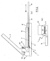
- FIGs 1 to 5 represent consecutive steps in the application of an apparatus 1 for filling cigarette tubes with tobacco.
- tobacco T for example loose tobacco
- a lid on the top side of the magazine chamber 2 is closed, the tobacco T can be compressed, see Figure 2 .
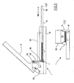
- the tobacco T is moved by means of a pusher and transferred into the area of a filling chamber 4, see Figure 3 .
- a press-down lever 6 is operated, i.e. pressed down, thereby shaping the tobacco in the filling chamber 4.
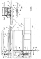
- the press-down lever 6 operates a coupling mechanism which drives a slider in order to transfer the tobacco from the filling chamber 4 into a cigarette tube 8 mounted at an end of filling chamber 4, see Figure 5 .
- the apparatus 1 comprises a base 10.
- the magazine chamber 2 comprises two side walls 14 which run in parallel to the arrow A in Figure 1(a) . In this direction, the magazine chamber 2 extends from a first end wall 16 to a second end wall 18. As is evident from the figures, the magazine chamber 2 is generally horizontally oriented.
- the top side of magazine chamber 2 can be closed by a lid 20.
- lid 20 At its longitudinal side edges, lid 20 is provided with guide steps 22, see Figure 1(b) .
- the lid 20 can be a separate part, as suggested by the figures, but it can also be connected to the walls of the magazine chamber 2, e.g., by hinge means.
- Figure 1 shows a state just after loose tobacco T has been filled into the magazine chamber 2, almost up to the upper edges of the side walls 14 and the second end wall 18.
- the user of apparatus 1 can compress the tobacco T.
- the highest compression state is achieved when the guide steps 22 of lid 20 abut against the upper edges of the side walls 14, but the guide steps 22 allow a smaller compression state as well.
- the user can freely select the compression state of the tobacco T according to his or her preferences.
- the compression state is also dependent on the total amount of tobacco T filled into the filling chamber 4 at the beginning, i.e. on its initial level in the filling chamber 4.
- Figures 1 and 2 show a pusher 24, which is designed as an elongate bar in the embodiment.
- the accessible portion of the pusher 24 can be defined as handle 26.
- the pusher 24 extends through a rectangular opening 28 in the second end wall 18, see Figures 1(b) and 2(b) . Due to its considerable thickness, the second end wall 18 acts as a guide for the pusher 24, see Figures 1(a) and 2(a) .
- Figure 3 shows a state when part of the tobacco supply has already been used for making cigarettes so that the total amount of tobacco T inside the magazine chamber 2 according to Figure 3 is smaller than according to Figures 1 and 2 . Due to frictional forces, the density of the tobacco T increases somewhat when the pusher 24 is moved further towards the first end 16, but the user can develop a sensitive feeling about that because the pusher 24 is operated by hand. After some trials, the user will learn how to end up with an optimum amount of tobacco in the filling chamber 4.
- lid 20 has been pressed all the way down, leaving only a small gap between the bottom face of lid 20 and pusher 24. But the apparatus 1 would also work when the distance between pusher 24 and the bottom of lid 20 is larger, i.e. when the tobacco T is less compressed.
- a stamp 30 can be vertically moved in a guide space 32 (see Figure 1(a) ) in front of the first end wall 16.
- the stamp 30 extends over the full width of magazine chamber 2, i.e. the inner distance of the side walls 14 in Figure 3(b) .
- the lower side 34 of stamp 30 has an essentially semi-circular cross-sectional shape, see Figure 3(a) .
- a cutter 36 is fixed to the side of stamp 30 opposite to the first end 16. The cutter 36 extends over the full width of stamp 30 and comprises a cutting edge 38 protruding somewhat at the lower side 34 of stamp 30.
- the stamp 30 When the press-down lever 6 is pressed down up to the end of its first part of travel, see Figure 4 , the stamp 30 has been moved to its lowermost position. During the downward movement of stamp 30, the cutter 36 cuts the tobacco to be filled into cigarette tube 8 from the rest of the tobacco T in magazine chamber 2, and the tobacco is shaped (which can include some further compression) and completely transferred into the filling chamber 4. As shown in Figure 4(a) , the filling chamber 4 has an essentially circular cross-section in this state, its upper portion being formed by the lower side 34 (see Figure 1(a) ) of stamp 30 and its lower portion formed by a trough-like recess in the base 10.
- socket 42 forms a mounting means for cigarette tube 8.
- socket 42 comprises an oblique end side 44.
- the socket 42 includes a step 46, which can be seen in Figure 5(d) .
- a threaded part 48 the socket 42 is screwed into a tapped hole in base 10. The figures do not show the clip which presses the paper of cigarette tube 8 against the socket 42 in order to ensure a safe attachment.
- a slider 50 can be moved in the direction of the longitudinal axis L of the filling chamber 4.
- the slider 50 has a conventional tongue-like extension 52 which extends over the full length or almost the full length of the filling chamber 4.
- the tongue-like extension 52 has an arcuate cross-sectional shape and can include undulated or serrated edges.
- the tongue-like extension 52 is mounted on a piston-like inner part 54 guided in a hollow guide cylinder 56 provided in base 10, see Figures 4(b) and 5(b) .
- a tab 58 protrudes at the end of part 54 opposite to the tongue-like extension 52.
- Tab 58 extends through a longitudinal slot in the guide cylinder 56.
- the guide cylinder 56 has approximately the length of filling chamber 4.
- the tab 58 is at one end of the travel path of slider 50, the tongue-like extension 52 being fully retracted inside the filling chamber 4.
- the tongue-like extension 52 emerges from the opening 40 and enters into the cigarette tube 8, thus transferring the tobacco of the filling chamber 4 into the cigarette tube 8.
- Figure 5(b) shows the end point of the travel path of slider 50.
- the press-down lever 6 is mounted in a bearing section 60 adjoining the guide space 32 of stamp 30. During the first part of its travel, the press-down lever 6 rotates about an axis which is called first fulcrum 62.
- the first fulcrum 62 is formed by a shaft, which is guided by an arcuate slot 64 on each side of the apparatus 1.
- the first fulcrum 62 rests at the lower end of the arcuate slots 64.
- spring means (not shown in the figures) which urge the shaft of the first fulcrum 62 towards the base 10.
- the upper area of the stamp 30 is connected to the press-down lever 6 by means of a hinge 66 allowing for some clearance as required when the stamp 30 is precisely guided in the guide space 32 (see Figure 1(a) ).
- the press-down lever 6 drives the stamp 30 towards the base 10 until a stop face 68 (see Figs. 3 (a) and 5(a) ) provided at the bearing section 60 is reached, see Figure 4(a) .
- an elbow lever 72 is a primary component of the coupling mechanism connecting the press-down lever 6 to the tab 58 of the slider 50.
- the elbow lever 72 comprises a first arm 74 and a second arm 76 and is swivelably mounted at a fixed pivot point 78.
- the first arm 74 is connected, by means of a joint, to a link piece 79 mounted to the shaft of the first fulcrum 62.
- the end of the second arm 76 is linked to a connection 80.
- Figures 4(c) and 5(c) demonstrate that the roughly vertically upward motion of the shaft of the first fulcrum 62 is translated into a roughly horizontal motion of the connection 80 in the area of base 10.
- the end of connection 80 is joined to a transmission lever 82 mounted at the end of a swivelable link bar 84.
- the transmission lever 82 is connected to tab 58 and increases the translational path length of the connection 80 to the translational path length required for driving the slider 50 along the filling chamber 4.
- the spring means acting onto the shaft of the first fulcrum 62 revert the motion of the components from the state shown in Figure 5 to that shown in Figure 4 , and additional spring means lift the press-down lever 6 including stamp 30 to its initial position shown in Figures 1 to 3 .
- the user can mount a fresh cigarette tube 8 and operate the apparatus 1 again, in the same way as described before.
- the supply of tobacco T in the magazine chamber 2 is sufficient for a large number of cigarettes.
- the magazine chamber 2 of the embodiment described by means of Figures 1 to 5 has a length (measured in the moving direction of pusher 24) of 18.0 cm (length of tobacco T in Figure 1(a) ) and a width (corresponding to the length of the filling chamber 4 in the longitudinal direction thereof) of 6.8 cm (or for shorter cigarettes, e.g., 6.2 cm).
- the height of magazine chamber 2 up to the upper edge of side walls 14 is 2.2 cm.
- the residual height of magazine chamber 2 is 1.0 cm.
- the pusher 24 can comprise marks which facilitate the positioning of the pusher, e.g., a mark for indicating the recommended starting position of the pusher after the mentioned shift of 4 cm or 5 cm (or more than one of such marks, depending on the kind of tobacco used) and marks for indicating subsequent moves in steps of one tobacco portion each.
- Figure 6 illustrates an embodiment of a packaging 100 for loose tobacco which comprises an insert 102 and a lid 104.
- the insert 102 is formed (e.g., from cardboard) as a trough-like part having a bottom wall 106 and two side walls 107 opposite to each other and being open at both end sides 108.
- the bottom wall 106 and the side walls 107 of the trough-like part 102 fit into gaps between the pusher 24 and the base wall 12 of the magazine chamber 2 and between the pusher 24 and the side walls 14 of the magazine chamber 2.
- the packaging 100 is closed by the lid 104 (e.g., of cardboard) covering the top side and the end sides 108 of the trough-like part 102 and overlapping the side walls 107 of the trough-like part 102.
- the packaging 100 is filled with tobacco (which, in that example, is somewhat pre-compressed).
- the closed packaging 100 is inserted in the magazine chamber 2 when the pusher 24 is in its fully retracted position. Thereafter, the lid 104 is lifted from the insert 102 and removed. The insert 102 can remain in the magazine chamber 2 because it does not interfere with the movement of the pusher 24.
- the edge walls of the lid of the packaging have a larger height than the side walls of the insert. This allows for a larger volume of tobacco in the packaging.
- the tobacco can be compressed by means of the lid 20 of the magazine chamber 2, as described above, because the downward movement of the lid 20 of the magazine chamber 2 is not impeded by any interfering parts of the packaging.
- FIG 7 shows another embodiment of a packaging 110 containing tobacco (here pre-compressed) to be transferred into magazine chamber 2.
- the packaging 110 comprises an insert 112 designed as in the embodiment of Figure 6 and a cover 114 made of flexible material, e.g., cardboard, paper, aluminum foil or plastic foil.
- the cover 114 is attached to the insert 112 via break lines 116.
- the cover 114 is gripped at a tab 118, pulled upwards, thus breaking the break lines 116, and removed, see Figure 7(b) .
- FIG. 8 A particular advantageous embodiment of a packaging 120 for tobacco is displayed in Figure 8 .
- the packaging 120 comprises a trough-like insert 122 which is designed as before.
- the open areas of the insert 122 are closed by a flexible cover 124 (e.g., of aluminum or plastic foil).
- the inner space defined by the insert 122 and the cover 124 has a larger height than the height of the side walls 125 of the through-like insert 122.
- this embodiment allows for a compression of the tobacco although the tobacco is still largely enclosed by the original packaging 120.
- a particular advantage of this embodiment is that the contact of the consumer's hands with the tobacco is minimised.
Landscapes
- Packaging Of Annular Or Rod-Shaped Articles, Wearing Apparel, Cassettes, Or The Like (AREA)
- Cigarettes, Filters, And Manufacturing Of Filters (AREA)
- Manufacture Of Tobacco Products (AREA)
Claims (20)
- Vorrichtung zum Füllen von Cigarettenhülsen mit Tabak, mit- einer Basis (10),- einer Magazinkammer (2), die dazu eingerichtet ist, einen Vorrat an Tabak (T) aufzunehmen und eine Basiswand (12), zwei einander gegenüberliegende Seitenwände (14), ein erstes Ende (16) und gegenüber dem ersten Ende (16) ein zweites Ende (18) aufweist,- einem Schieber (24), der dazu eingerichtet ist, den Tabak (T) innerhalb der Magazinkammer (2) auf das erste Ende zu (16) zu bewegen,- einer Füllkammer (4) nahe dem ersten Ende (16) der Magazinkammer (2), die eine Längsrichtung (L) quer zu der Bewegungsrichtung (A) des Schiebers (24) definiert und dazu eingerichtet ist, den in die Cigarettenhülse (8) zu füllenden Tabak aufzunehmen,- einem Stempel (30), der in einer Richtung quer zu der Bewegungsrichtung (A) des Schiebers (24) und quer zu der Längsrichtung (L) der Füllkammer (4) bewegbar ist und dazu eingerichtet ist, den Tabak in der Füllkammer (4) zu formen,- einer in der Füllkammer (4) angeordneten Schiebeeinrichtung (50), die in deren Längsrichtung (L) auf eine Öffnung (40) in einer Stirnseite davon bewegbar ist und die dazu eingerichtet ist, den Tabak der Füllkammer (4) von der Füllkammer (4) über diese Öffnung (40) in eine vor der Öffnung (40) gehaltene Cigarettenhülse (8) zu übertragen,- einem herunterdrückbaren Hebel (6), der betriebsmäßig mit dem Stempel (30) verbunden und dazu eingerichtet ist, den Stempel (30) zu bewegen,
gekennzeichnet durch- einen Deckel (20), der dazu eingerichtet ist, die Oberseite der Magazinkammer (2) zu schließen,- einen Kupplungsmechanismus (72, 79, 80, 82, 84), der betriebsmäßig mit dem herunterdrückbaren Hebel (6) verbunden und dazu eingerichtet ist, die Schiebeeinrichtung (50) zu bewegen, nachdem der Tabak in die Füllkammer (4) übertragen und von dem Stempel (30) geformt worden ist. - Vorrichtung nach Anspruch 1, dadurch gekennzeichnet, dass der Schieber (24) einen manuellen Betätigungsgriff (26) aufweist.
- Vorrichtung nach Anspruch 2, dadurch gekennzeichnet, dass der manuelle Betätigungsgriff (26) an einem Schaft angeordnet ist, der sich durch eine Öffnung (28) am zweiten Ende (18) der Magazinkammer (2) erstreckt, wobei der Schaft vorzugsweise Markierungen zum Anzeigen der Weglänge aufweist, über die der Tabak bereits von dem Schieber (24) bewegt worden ist.
- Vorrichtung nach einem der Ansprüche 1 bis 3, dadurch gekennzeichnet, dass der Deckel (20) in Bezug auf die Magazinkammer (2) verschiebbar geführt und dazu eingerichtet ist, das Volumen der Magazinkammer (2) durch Drücken des Deckels (20) nach unten zu verringern, wobei der Deckel (20) vorzugsweise eine als Stufe (22) ausgebildete Führungseinrichtung aufweist.
- Vorrichtung nach einem der Ansprüche 1 bis 4, gekennzeichnet durch eine Schneideinrichtung (36), die dazu eingerichtet ist, den in die Füllkammer (4) zu übertragenden Tabak von dem Rest des Tabaks (T) der Magazinkammer (2) abzutrennen, wobei die Schneideinrichtung (36) vorzugsweise fest an dem Stempel (30) angebracht ist.
- Vorrichtung nach einem der Ansprüche 1 bis 5, gekennzeichnet durch eine Ansatzhülse (42), die um die Öffnung (40) der Füllkammer (4) herum angeordnet und dazu eingerichtet ist, eine Cigarettenhülse (8) zu halten, wobei die Ansatzhülse (42) vorzugsweise eine Stufe (46) an ihrer Innenseite aufweist.
- Vorrichtung nach einem der Ansprüche 1 bis 6, dadurch gekennzeichnet, dass die Schiebeeinrichtung (50) eine zungenähnliche Verlängerung (52) aufweist, die von einem kolbenähnlichen inneren Teil (54) ausgeht, wobei die zungenähnliche Verlängerung (52) in die Cigarettenhülse (8) eindringt, wenn die Schiebeeinrichtung (50) auf die Öffnung (40) der Füllkammer (4) zu bewegt wird.
- Vorrichtung nach einem der Ansprüche 1 bis 7, dadurch gekennzeichnet, dass in der untersten Position des Stempels (30) die Querschnittsform der Füllkammer (4) einschließlich ihres durch den Stempel (30) definierten oberen Bereichs kreisähnlich ist.
- Vorrichtung nach einem der Ansprüche 1 bis 8, dadurch gekennzeichnet, dass der herunterdrückbare Hebel (6) zwei Hebeldrehpunkte hat, einen ersten Hebeldrehpunkt (62) und einen zweiten Hebeldrehpunkt (70), die dazu eingerichtet sind, während verschiedener Abschnitte der Betätigung des herunterdrückbaren Hebels (6) als Hebeldrehpunkte zu wirken, wobei während des ersten Teils der Bewegung des herunterdrückbaren Hebels (6), der mit der Bewegung des Stempels (30) verknüpft ist, der erste Hebeldrehpunkt (62) als Hebeldrehpunkt wirkt und sich der zweite Hebeldrehpunkt (70) nach unten bewegt, und wobei während des zweiten Teils der Bewegung des herunterdrückbaren Hebels (6), der mit der Bewegung der Schiebeeinrichtung (50) verknüpft ist, der zweite Hebeldrehpunkt (70) als Hebeldrehpunkt wirkt und der erste Hebeldrehpunkt (62) sich nach oben bewegt.
- Vorrichtung nach Anspruch 9, dadurch gekennzeichnet, dass der erste Hebeldrehpunkt (62) dazu eingerichtet ist, durch eine Federeinrichtung in Position gehalten zu werden, solange er als Hebeldrehpunkt wirkt.
- Vorrichtung nach Anspruch 10, dadurch gekennzeichnet, dass der zweite Hebeldrehpunkt (70), solange er als Hebeldrehpunkt wirkt, an einer Anschlagfläche (68) ausgebildet ist, die den ersten Teil der Bewegung des herunterdrückbaren Hebels (6) begrenzt, wobei der erste Hebeldrehpunkt (62) während des zweiten Teils der Bewegung des herunterdrückbaren Hebels (6) gegen Federkraft angehoben wird.
- Vorrichtung nach einem der Ansprüche 9 bis 11, dadurch gekennzeichnet, dass der zum Bewegen der Schiebeeinrichtung (50) eingerichtete Kopplungsmechanismus (72, 79, 80, 82, 84) einen Kniehebel (72) mit einem ersten Hebelarm (74) und einem zweiten Hebelarm (76) aufweist, wobei der erste Hebelarm (74) betriebsmäßig mit dem ersten Hebeldrehpunkt (62) verbunden und der zweite Hebelarm (76) dazu eingerichtet ist, sich im Wesentlichen parallel zu der Bewegungsrichtung der Schiebeeinrichtung (50) zu bewegen, wenn der erste Hebeldrehpunkt (62) angehoben wird.
- Vorrichtung nach Anspruch 12, dadurch gekennzeichnet, dass der zweite Hebelarm (76) des Kniehebels (72) über zusätzliche Verbindungsglieder (80, 82, 84) mit der Schiebeeinrichtung (50) verbunden ist.
- System mit- einer Vorrichtung (1) nach einem der Ansprüche 1 bis 13 und- vorgerichtetem Tabak zum Einfüllen in die Magazinkammer (2) der Vorrichtung.
- System nach Anspruch 14, dadurch gekennzeichnet, dass der vorgerichtete Tabak losen Tabak aufweist, der in einer Packung (100; 110; 120) enthalten ist, die sowohl einen in die Magazinkammer (2) passenden und den Tabak haltenden Einsatz (102; 112; 122) als auch eine Verschlusseinrichtung (104; 114; 124) aufweist.
- System nach Anspruch 15, dadurch gekennzeichnet, dass der Einsatz (102; 112; 122) ein trogähnliches Teil (102; 112; 122) mit einer Bodenwand (106) und zwei einander gegenüberliegenden Seitenwänden (107) und offenstehenden Endseiten (108) aufweist, wobei die Bodenwand (106) und die Seitenwände (107) des trogähnlichen Teils (102; 112; 122) in die Lücken zwischen dem Schieber (24) und der Basiswand (12) beziehungsweise den Seitenwänden (14) der Magazinkammer (2) passen.
- System nach Anspruch 16, dadurch gekennzeichnet, dass die Verschlusseinrichtung (104) einen hebbaren Deckel (104) aufweist, der die Oberseite und die Endseiten des trogähnlichen Teils (102) schließt und mit den Seitenwänden (107) des trogähnlichen Teils (102) überlappt.
- System nach Anspruch 16, dadurch gekennzeichnet, dass die Verschlusseinrichtung (114) eine Abdeckung (114), vorzugsweise aus flexiblem Material, aufweist, die die Oberseite und die Endseiten des trogähnlichen Teils (112) schließt, wobei die Abdeckung (114) mit dem trogähnlichen Teil (112) entlang von Bruchlinien (116) verbunden ist.
- System nach Anspruch 16, dadurch gekennzeichnet, dass die Verschlusseinrichtung (124) eine flexible Abdeckung (124) aufweist, die die Oberseite und die Endseiten des trogähnlichen Teils (122) schließt, wobei der von dem trogähnlichen Teil (122) und der Abdeckung (124) definierte Innenraum eine größere Höhe als die Höhe der Seitenwände (125) des trogähnlichen Teils (122) hat, und wobei die Abdeckung (124) im Bereich der Endseiten des trogähnlichen Teils (122) entfernbare Teile (126) hat.
- System nach Anspruch 14, dadurch gekennzeichnet, dass der vorgerichtete Tabak einen Block aus zusammenhängendem Tabak aufweist.
Priority Applications (11)
| Application Number | Priority Date | Filing Date | Title |
|---|---|---|---|
| EP08400012A EP2103227B1 (de) | 2008-03-17 | 2008-03-17 | Vorrichtung zum Stopfen von Zigarettenhülsen mit Tabak |
| AT08400012T ATE485732T1 (de) | 2008-03-17 | 2008-03-17 | Vorrichtung zum stopfen von zigarettenhülsen mit tabak |
| DE602008003192T DE602008003192D1 (de) | 2008-03-17 | 2008-03-17 | Vorrichtung zum Stopfen von Zigarettenhülsen mit Tabak |
| ES08400012T ES2352834T3 (es) | 2008-03-17 | 2008-03-17 | Aparato para llenar tubos de cigarrillos con tabaco. |
| CA2717791A CA2717791C (en) | 2008-03-17 | 2009-03-17 | Apparatus for filling cigarette tubes with tobacco |
| AU2009226739A AU2009226739B2 (en) | 2008-03-17 | 2009-03-17 | Apparatus for filling cigarette tubes with tobacco |
| EP09723527.9A EP2257193B1 (de) | 2008-03-17 | 2009-03-17 | Vorrichtung zum stopfen von zigarettenhülsen mit tabak |
| NZ587836A NZ587836A (en) | 2008-03-17 | 2009-03-17 | Manual apparatus for filling cigarette tubes with tobacco |
| ES09723527.9T ES2579233T3 (es) | 2008-03-17 | 2009-03-17 | Aparato para llenar tubos de cigarrillo con tabaco |
| US12/922,844 US8863751B2 (en) | 2008-03-17 | 2009-03-17 | Apparatus for filling cigarette tubes with tobacco |
| PCT/EP2009/001961 WO2009115297A1 (en) | 2008-03-17 | 2009-03-17 | Apparatus for filling cigarette tubes with tobacco |
Applications Claiming Priority (1)
| Application Number | Priority Date | Filing Date | Title |
|---|---|---|---|
| EP08400012A EP2103227B1 (de) | 2008-03-17 | 2008-03-17 | Vorrichtung zum Stopfen von Zigarettenhülsen mit Tabak |
Publications (2)
| Publication Number | Publication Date |
|---|---|
| EP2103227A1 EP2103227A1 (de) | 2009-09-23 |
| EP2103227B1 true EP2103227B1 (de) | 2010-10-27 |
Family
ID=39643020
Family Applications (2)
| Application Number | Title | Priority Date | Filing Date |
|---|---|---|---|
| EP08400012A Not-in-force EP2103227B1 (de) | 2008-03-17 | 2008-03-17 | Vorrichtung zum Stopfen von Zigarettenhülsen mit Tabak |
| EP09723527.9A Not-in-force EP2257193B1 (de) | 2008-03-17 | 2009-03-17 | Vorrichtung zum stopfen von zigarettenhülsen mit tabak |
Family Applications After (1)
| Application Number | Title | Priority Date | Filing Date |
|---|---|---|---|
| EP09723527.9A Not-in-force EP2257193B1 (de) | 2008-03-17 | 2009-03-17 | Vorrichtung zum stopfen von zigarettenhülsen mit tabak |
Country Status (9)
| Country | Link |
|---|---|
| US (1) | US8863751B2 (de) |
| EP (2) | EP2103227B1 (de) |
| AT (1) | ATE485732T1 (de) |
| AU (1) | AU2009226739B2 (de) |
| CA (1) | CA2717791C (de) |
| DE (1) | DE602008003192D1 (de) |
| ES (2) | ES2352834T3 (de) |
| NZ (1) | NZ587836A (de) |
| WO (1) | WO2009115297A1 (de) |
Families Citing this family (7)
| Publication number | Priority date | Publication date | Assignee | Title |
|---|---|---|---|---|
| US20120312311A1 (en) * | 2011-06-10 | 2012-12-13 | Republic Tobacco L.P. | Cigarette-Making Machines and Methods of Using the Same |
| CN103445291B (zh) * | 2012-06-05 | 2016-04-06 | 公共烟草有限合伙公司 | 家用卷烟器的烟丝注射结构以及家用卷烟器 |
| GB2511559B (en) | 2013-03-07 | 2018-11-14 | Mondelez Uk R&D Ltd | Improved Packaging and Method of Forming Packaging |
| GB2511560B (en) | 2013-03-07 | 2018-11-14 | Mondelez Uk R&D Ltd | Improved Packaging and Method of Forming Packaging |
| ES2644328T3 (es) * | 2013-05-24 | 2017-11-28 | Pt Mitra Prodin | Aparato de llenado de tubos |
| US11369134B2 (en) | 2018-11-13 | 2022-06-28 | Gevorg Gabrielyan | Apparatuses and methods for filling and packing herb receptacles with herb material |
| US11571016B2 (en) * | 2019-07-05 | 2023-02-07 | II Thomas Allen Kittle | Piston device for loading smoking material into a tube |
Family Cites Families (11)
| Publication number | Priority date | Publication date | Assignee | Title |
|---|---|---|---|---|
| US2731971A (en) | 1956-01-24 | Cigarette making machine | ||
| US3127900A (en) | 1961-01-25 | 1964-04-07 | Kastner Arnold | Cigarette machine |
| DE2139242C3 (de) * | 1971-08-05 | 1974-02-07 | Efka-Werke Fritz Kiehn Gmbh, 7218 Trossingen | Handstopfgerät für Zigarettenhülsen, insbesondere für Zigarettenfllterhülsen |
| GB1556346A (en) * | 1977-12-21 | 1979-11-21 | Rizla Ltd | Manually operated cigarette making machine |
| US4411278A (en) | 1981-07-24 | 1983-10-25 | Arnold Kastner | Cigarette making machine |
| CA1329100C (en) * | 1988-05-16 | 1994-05-03 | Arnold Kastner | Portable manually operable cigarette making machine |
| DE4228227A1 (de) | 1992-08-25 | 1994-03-03 | Efka Werke Kiehn Gmbh Fritz | Rauchtabak für die Selbstverfertigung einer Zigarette sowie Vorrichtung dafür |
| ES2358535T3 (es) * | 2005-06-10 | 2011-05-11 | Philip Morris Products S.A. | Caja que contiene material suelto que se puede fumar. |
| DE202005012273U1 (de) | 2005-07-29 | 2005-10-20 | Reemtsma Cigarettenfabriken Gmbh | Stopfvorrichtung für Tabak |
| US20070193591A1 (en) * | 2006-01-19 | 2007-08-23 | Philip Morris Usa Inc. | Unknown |
| US7789087B2 (en) | 2006-04-28 | 2010-09-07 | Philip Morris Usa Inc. | Tabletop cigarette maker |
-
2008
- 2008-03-17 AT AT08400012T patent/ATE485732T1/de not_active IP Right Cessation
- 2008-03-17 ES ES08400012T patent/ES2352834T3/es active Active
- 2008-03-17 EP EP08400012A patent/EP2103227B1/de not_active Not-in-force
- 2008-03-17 DE DE602008003192T patent/DE602008003192D1/de active Active
-
2009
- 2009-03-17 CA CA2717791A patent/CA2717791C/en active Active
- 2009-03-17 US US12/922,844 patent/US8863751B2/en active Active
- 2009-03-17 ES ES09723527.9T patent/ES2579233T3/es active Active
- 2009-03-17 NZ NZ587836A patent/NZ587836A/en not_active IP Right Cessation
- 2009-03-17 EP EP09723527.9A patent/EP2257193B1/de not_active Not-in-force
- 2009-03-17 AU AU2009226739A patent/AU2009226739B2/en not_active Ceased
- 2009-03-17 WO PCT/EP2009/001961 patent/WO2009115297A1/en not_active Ceased
Also Published As
| Publication number | Publication date |
|---|---|
| AU2009226739B2 (en) | 2013-05-23 |
| ES2352834T3 (es) | 2011-02-23 |
| NZ587836A (en) | 2012-03-30 |
| DE602008003192D1 (de) | 2010-12-09 |
| US8863751B2 (en) | 2014-10-21 |
| EP2103227A1 (de) | 2009-09-23 |
| EP2257193A1 (de) | 2010-12-08 |
| CA2717791A1 (en) | 2009-09-24 |
| US20110114104A1 (en) | 2011-05-19 |
| ATE485732T1 (de) | 2010-11-15 |
| WO2009115297A1 (en) | 2009-09-24 |
| AU2009226739A1 (en) | 2009-09-24 |
| CA2717791C (en) | 2015-11-17 |
| ES2579233T3 (es) | 2016-08-08 |
| EP2257193B1 (de) | 2016-05-11 |
Similar Documents
| Publication | Publication Date | Title |
|---|---|---|
| EP2103227B1 (de) | Vorrichtung zum Stopfen von Zigarettenhülsen mit Tabak | |
| US8464867B2 (en) | Package for tobacco-related articles | |
| EP1981362B1 (de) | Vorrichtung zum füllen von zigarettenhülsen mit tabak | |
| EP2023779B1 (de) | Kollektion mit einer ausgabeanordnung und schneideinrichtung für hüllen, dessen verwendung und entsprechendes verfahren | |
| HU231111B1 (hu) | Cigarettadohány tömörítő szerkezet, cigarettatöltő gép és eljárás különböző hosszúságú cigaretták előállítására | |
| EP2319332A1 (de) | Vorrichtung zum Stopfen von Zigarettenhülsen mit Tabak | |
| US20080250943A1 (en) | Systems and Methods for Dispensing Food | |
| US8567411B2 (en) | System for self-assembly of cigarettes | |
| KR101752688B1 (ko) | 식품포장재 케이스 | |
| KR20250124390A (ko) | 쉴드를 갖춘 비누 디스펜서 | |
| KR20250149667A (ko) | 비누 스트립 디스펜서 | |
| JPH0346958Y2 (de) | ||
| EP2598424A1 (de) | Verpackung zur ausgabe und verfahren zur längentrennung eines packmaterials | |
| JP3122873U (ja) | 紙巻器 |
Legal Events
| Date | Code | Title | Description |
|---|---|---|---|
| PUAI | Public reference made under article 153(3) epc to a published international application that has entered the european phase |
Free format text: ORIGINAL CODE: 0009012 |
|
| 17P | Request for examination filed |
Effective date: 20080924 |
|
| AK | Designated contracting states |
Kind code of ref document: A1 Designated state(s): AT BE BG CH CY CZ DE DK EE ES FI FR GB GR HR HU IE IS IT LI LT LU LV MC MT NL NO PL PT RO SE SI SK TR |
|
| AX | Request for extension of the european patent |
Extension state: AL BA MK RS |
|
| GRAP | Despatch of communication of intention to grant a patent |
Free format text: ORIGINAL CODE: EPIDOSNIGR1 |
|
| AKX | Designation fees paid |
Designated state(s): AT BE BG CH CY CZ DE DK EE ES FI FR GB GR HR HU IE IS IT LI LT LU LV MC MT NL NO PL PT RO SE SI SK TR |
|
| GRAS | Grant fee paid |
Free format text: ORIGINAL CODE: EPIDOSNIGR3 |
|
| GRAA | (expected) grant |
Free format text: ORIGINAL CODE: 0009210 |
|
| AK | Designated contracting states |
Kind code of ref document: B1 Designated state(s): AT BE BG CH CY CZ DE DK EE ES FI FR GB GR HR HU IE IS IT LI LT LU LV MC MT NL NO PL PT RO SE SI SK TR |
|
| REG | Reference to a national code |
Ref country code: GB Ref legal event code: FG4D |
|
| REG | Reference to a national code |
Ref country code: CH Ref legal event code: EP |
|
| REG | Reference to a national code |
Ref country code: IE Ref legal event code: FG4D |
|
| REG | Reference to a national code |
Ref country code: NL Ref legal event code: T3 |
|
| REF | Corresponds to: |
Ref document number: 602008003192 Country of ref document: DE Date of ref document: 20101209 Kind code of ref document: P |
|
| REG | Reference to a national code |
Ref country code: ES Ref legal event code: FG2A Effective date: 20110211 |
|
| LTIE | Lt: invalidation of european patent or patent extension |
Effective date: 20101027 |
|
| PG25 | Lapsed in a contracting state [announced via postgrant information from national office to epo] |
Ref country code: NO Free format text: LAPSE BECAUSE OF FAILURE TO SUBMIT A TRANSLATION OF THE DESCRIPTION OR TO PAY THE FEE WITHIN THE PRESCRIBED TIME-LIMIT Effective date: 20110127 Ref country code: LT Free format text: LAPSE BECAUSE OF FAILURE TO SUBMIT A TRANSLATION OF THE DESCRIPTION OR TO PAY THE FEE WITHIN THE PRESCRIBED TIME-LIMIT Effective date: 20101027 |
|
| PG25 | Lapsed in a contracting state [announced via postgrant information from national office to epo] |
Ref country code: HR Free format text: LAPSE BECAUSE OF FAILURE TO SUBMIT A TRANSLATION OF THE DESCRIPTION OR TO PAY THE FEE WITHIN THE PRESCRIBED TIME-LIMIT Effective date: 20101027 Ref country code: AT Free format text: LAPSE BECAUSE OF FAILURE TO SUBMIT A TRANSLATION OF THE DESCRIPTION OR TO PAY THE FEE WITHIN THE PRESCRIBED TIME-LIMIT Effective date: 20101027 Ref country code: IS Free format text: LAPSE BECAUSE OF FAILURE TO SUBMIT A TRANSLATION OF THE DESCRIPTION OR TO PAY THE FEE WITHIN THE PRESCRIBED TIME-LIMIT Effective date: 20110227 Ref country code: FI Free format text: LAPSE BECAUSE OF FAILURE TO SUBMIT A TRANSLATION OF THE DESCRIPTION OR TO PAY THE FEE WITHIN THE PRESCRIBED TIME-LIMIT Effective date: 20101027 Ref country code: BG Free format text: LAPSE BECAUSE OF FAILURE TO SUBMIT A TRANSLATION OF THE DESCRIPTION OR TO PAY THE FEE WITHIN THE PRESCRIBED TIME-LIMIT Effective date: 20110127 Ref country code: SE Free format text: LAPSE BECAUSE OF FAILURE TO SUBMIT A TRANSLATION OF THE DESCRIPTION OR TO PAY THE FEE WITHIN THE PRESCRIBED TIME-LIMIT Effective date: 20101027 Ref country code: LV Free format text: LAPSE BECAUSE OF FAILURE TO SUBMIT A TRANSLATION OF THE DESCRIPTION OR TO PAY THE FEE WITHIN THE PRESCRIBED TIME-LIMIT Effective date: 20101027 Ref country code: SI Free format text: LAPSE BECAUSE OF FAILURE TO SUBMIT A TRANSLATION OF THE DESCRIPTION OR TO PAY THE FEE WITHIN THE PRESCRIBED TIME-LIMIT Effective date: 20101027 Ref country code: PT Free format text: LAPSE BECAUSE OF FAILURE TO SUBMIT A TRANSLATION OF THE DESCRIPTION OR TO PAY THE FEE WITHIN THE PRESCRIBED TIME-LIMIT Effective date: 20110228 |
|
| PG25 | Lapsed in a contracting state [announced via postgrant information from national office to epo] |
Ref country code: BE Free format text: LAPSE BECAUSE OF FAILURE TO SUBMIT A TRANSLATION OF THE DESCRIPTION OR TO PAY THE FEE WITHIN THE PRESCRIBED TIME-LIMIT Effective date: 20101027 Ref country code: GR Free format text: LAPSE BECAUSE OF FAILURE TO SUBMIT A TRANSLATION OF THE DESCRIPTION OR TO PAY THE FEE WITHIN THE PRESCRIBED TIME-LIMIT Effective date: 20110128 |
|
| PG25 | Lapsed in a contracting state [announced via postgrant information from national office to epo] |
Ref country code: EE Free format text: LAPSE BECAUSE OF FAILURE TO SUBMIT A TRANSLATION OF THE DESCRIPTION OR TO PAY THE FEE WITHIN THE PRESCRIBED TIME-LIMIT Effective date: 20101027 Ref country code: CZ Free format text: LAPSE BECAUSE OF FAILURE TO SUBMIT A TRANSLATION OF THE DESCRIPTION OR TO PAY THE FEE WITHIN THE PRESCRIBED TIME-LIMIT Effective date: 20101027 |
|
| PG25 | Lapsed in a contracting state [announced via postgrant information from national office to epo] |
Ref country code: RO Free format text: LAPSE BECAUSE OF FAILURE TO SUBMIT A TRANSLATION OF THE DESCRIPTION OR TO PAY THE FEE WITHIN THE PRESCRIBED TIME-LIMIT Effective date: 20101027 Ref country code: SK Free format text: LAPSE BECAUSE OF FAILURE TO SUBMIT A TRANSLATION OF THE DESCRIPTION OR TO PAY THE FEE WITHIN THE PRESCRIBED TIME-LIMIT Effective date: 20101027 Ref country code: PL Free format text: LAPSE BECAUSE OF FAILURE TO SUBMIT A TRANSLATION OF THE DESCRIPTION OR TO PAY THE FEE WITHIN THE PRESCRIBED TIME-LIMIT Effective date: 20101027 Ref country code: DK Free format text: LAPSE BECAUSE OF FAILURE TO SUBMIT A TRANSLATION OF THE DESCRIPTION OR TO PAY THE FEE WITHIN THE PRESCRIBED TIME-LIMIT Effective date: 20101027 |
|
| PLBE | No opposition filed within time limit |
Free format text: ORIGINAL CODE: 0009261 |
|
| STAA | Information on the status of an ep patent application or granted ep patent |
Free format text: STATUS: NO OPPOSITION FILED WITHIN TIME LIMIT |
|
| 26N | No opposition filed |
Effective date: 20110728 |
|
| PG25 | Lapsed in a contracting state [announced via postgrant information from national office to epo] |
Ref country code: MC Free format text: LAPSE BECAUSE OF NON-PAYMENT OF DUE FEES Effective date: 20110331 |
|
| REG | Reference to a national code |
Ref country code: DE Ref legal event code: R097 Ref document number: 602008003192 Country of ref document: DE Effective date: 20110728 |
|
| PG25 | Lapsed in a contracting state [announced via postgrant information from national office to epo] |
Ref country code: MT Free format text: LAPSE BECAUSE OF FAILURE TO SUBMIT A TRANSLATION OF THE DESCRIPTION OR TO PAY THE FEE WITHIN THE PRESCRIBED TIME-LIMIT Effective date: 20101027 Ref country code: IT Free format text: LAPSE BECAUSE OF FAILURE TO SUBMIT A TRANSLATION OF THE DESCRIPTION OR TO PAY THE FEE WITHIN THE PRESCRIBED TIME-LIMIT Effective date: 20101027 |
|
| REG | Reference to a national code |
Ref country code: IE Ref legal event code: MM4A |
|
| PG25 | Lapsed in a contracting state [announced via postgrant information from national office to epo] |
Ref country code: IE Free format text: LAPSE BECAUSE OF NON-PAYMENT OF DUE FEES Effective date: 20110317 |
|
| REG | Reference to a national code |
Ref country code: CH Ref legal event code: PL |
|
| PG25 | Lapsed in a contracting state [announced via postgrant information from national office to epo] |
Ref country code: LI Free format text: LAPSE BECAUSE OF NON-PAYMENT OF DUE FEES Effective date: 20120331 Ref country code: CH Free format text: LAPSE BECAUSE OF NON-PAYMENT OF DUE FEES Effective date: 20120331 |
|
| PG25 | Lapsed in a contracting state [announced via postgrant information from national office to epo] |
Ref country code: CY Free format text: LAPSE BECAUSE OF FAILURE TO SUBMIT A TRANSLATION OF THE DESCRIPTION OR TO PAY THE FEE WITHIN THE PRESCRIBED TIME-LIMIT Effective date: 20101027 Ref country code: LU Free format text: LAPSE BECAUSE OF NON-PAYMENT OF DUE FEES Effective date: 20110317 |
|
| PG25 | Lapsed in a contracting state [announced via postgrant information from national office to epo] |
Ref country code: TR Free format text: LAPSE BECAUSE OF FAILURE TO SUBMIT A TRANSLATION OF THE DESCRIPTION OR TO PAY THE FEE WITHIN THE PRESCRIBED TIME-LIMIT Effective date: 20101027 |
|
| PG25 | Lapsed in a contracting state [announced via postgrant information from national office to epo] |
Ref country code: HU Free format text: LAPSE BECAUSE OF FAILURE TO SUBMIT A TRANSLATION OF THE DESCRIPTION OR TO PAY THE FEE WITHIN THE PRESCRIBED TIME-LIMIT Effective date: 20101027 |
|
| REG | Reference to a national code |
Ref country code: FR Ref legal event code: PLFP Year of fee payment: 9 |
|
| REG | Reference to a national code |
Ref country code: FR Ref legal event code: PLFP Year of fee payment: 10 |
|
| PGFP | Annual fee paid to national office [announced via postgrant information from national office to epo] |
Ref country code: FR Payment date: 20170221 Year of fee payment: 10 Ref country code: DE Payment date: 20170222 Year of fee payment: 10 |
|
| PGFP | Annual fee paid to national office [announced via postgrant information from national office to epo] |
Ref country code: NL Payment date: 20170221 Year of fee payment: 10 Ref country code: GB Payment date: 20170224 Year of fee payment: 10 |
|
| PGFP | Annual fee paid to national office [announced via postgrant information from national office to epo] |
Ref country code: ES Payment date: 20170222 Year of fee payment: 10 |
|
| REG | Reference to a national code |
Ref country code: DE Ref legal event code: R119 Ref document number: 602008003192 Country of ref document: DE |
|
| REG | Reference to a national code |
Ref country code: NL Ref legal event code: MM Effective date: 20180401 |
|
| GBPC | Gb: european patent ceased through non-payment of renewal fee |
Effective date: 20180317 |
|
| PG25 | Lapsed in a contracting state [announced via postgrant information from national office to epo] |
Ref country code: NL Free format text: LAPSE BECAUSE OF NON-PAYMENT OF DUE FEES Effective date: 20180401 |
|
| PG25 | Lapsed in a contracting state [announced via postgrant information from national office to epo] |
Ref country code: DE Free format text: LAPSE BECAUSE OF NON-PAYMENT OF DUE FEES Effective date: 20181002 |
|
| PG25 | Lapsed in a contracting state [announced via postgrant information from national office to epo] |
Ref country code: GB Free format text: LAPSE BECAUSE OF NON-PAYMENT OF DUE FEES Effective date: 20180317 |
|
| PG25 | Lapsed in a contracting state [announced via postgrant information from national office to epo] |
Ref country code: FR Free format text: LAPSE BECAUSE OF NON-PAYMENT OF DUE FEES Effective date: 20180331 |
|
| REG | Reference to a national code |
Ref country code: ES Ref legal event code: FD2A Effective date: 20190911 |
|
| PG25 | Lapsed in a contracting state [announced via postgrant information from national office to epo] |
Ref country code: ES Free format text: LAPSE BECAUSE OF NON-PAYMENT OF DUE FEES Effective date: 20180318 |