EP2103202B1 - Work block for chopping and/or grinding vegetables designed to be carried by a carrier vehicle by means of an arm - Google Patents
Work block for chopping and/or grinding vegetables designed to be carried by a carrier vehicle by means of an arm Download PDFInfo
- Publication number
- EP2103202B1 EP2103202B1 EP20090305214 EP09305214A EP2103202B1 EP 2103202 B1 EP2103202 B1 EP 2103202B1 EP 20090305214 EP20090305214 EP 20090305214 EP 09305214 A EP09305214 A EP 09305214A EP 2103202 B1 EP2103202 B1 EP 2103202B1
- Authority
- EP
- European Patent Office
- Prior art keywords
- work block
- work
- coupling part
- coupling piece
- block according
- Prior art date
- Legal status (The legal status is an assumption and is not a legal conclusion. Google has not performed a legal analysis and makes no representation as to the accuracy of the status listed.)
- Not-in-force
Links
Images


Classifications
-
- A—HUMAN NECESSITIES
- A01—AGRICULTURE; FORESTRY; ANIMAL HUSBANDRY; HUNTING; TRAPPING; FISHING
- A01D—HARVESTING; MOWING
- A01D34/00—Mowers; Mowing apparatus of harvesters
- A01D34/835—Mowers; Mowing apparatus of harvesters specially adapted for particular purposes
- A01D34/86—Mowers; Mowing apparatus of harvesters specially adapted for particular purposes for use on sloping ground, e.g. on embankments or in ditches
- A01D34/866—Mounting means
Definitions
- the present invention generally relates to work blocks used for cutting and / or crushing plants such as bulldozers used to maintain green spaces, for example road borders, ditches, embankments, ensuring mowing and brushing.
- These work blocks comprise a rotor carrying cutting tools working in the manner of flails during the rotation of said rotor.
- the constitution of cutting tools related to the speed of rotation of the rotor makes it possible to use such blocks of cutting and / or grinding work both for cutting grass or brush, for pruning trees or trimming a hedge.
- Such work blocks are carried by a public works machine or a tractor by means of an arm usually disposed at the rear of the carrier vehicle. Said arm extends generally perpendicular to the direction of movement of said vehicle so that the work block is positioned on the side of the vehicle during work.
- the rotor of the work block is positioned in a horizontal plane generally parallel to the ground while for a size work of a hedge, the work block is raised by the arm and said rotor is in a globally vertical plan.
- the working block A is pulled by the support arm B which on the one hand, avoids the phenomena of drowning of said work block, that is to say the tendency of it to sink into the ground , during work and provides a better quality cut by maintaining the cutting height substantially constant.
- the driver of the vehicle is thus released from the need to monitor and adjust the height of the work block during the work.
- a coupling piece E is interposed between a horizontal shaft D carried by the arm B and the working block A.
- This coupling piece E is generally composed of a beam 1 and two arms 2 arranged
- the beam 1 is intended to be positioned in a U-shaped iron 5 carried by the horizontal shaft D to couple the working block A to the arm B.
- the front ends of the arms 2 are hung on the yokes 3 positioned at the top. front of work block A by means of journals 4.
- the work block A is pulled by the arms 2 and movable in rotation about the axis XX defined by the journals 4.
- the work block coupled to the arm by the coupling piece E is free to rotate relative to the coupling piece.
- the movement of the work block around the axis XX is then practically unpredictable since it depends on the inclination of the work block, the inclination of the hydraulic arm, the shape of the ground and the presence of obstacles such as only big branches that the work block can not cut.
- the work is not of good quality.
- changes in the position of the work block are often abrupt and significantly alter the distribution of masses on the carrier vehicle which can cause the reversal of it if it is already subject to an imbalance due to uneven terrain.
- the object of the present invention is therefore to provide an improvement to the work blocks for cutting and / or crushing plants making it possible to use them under good conditions whether on the ground or at the height without requiring the modification of the hitch of said working block on the support arm.
- the plant cutting and / or grinding work block intended to be carried by a carrier vehicle via an arm and having a coupling piece mounted free to rotate on its before is characterized in that it carries a guide butt of said coupling piece and low and high stops limiting the rotational movement of said coupling piece.
- such an assembly according to the invention makes it possible to obtain a discontinuity of the coupling of the work block to the carrier vehicle at the level of the guide butt, because the only articulations brought to work are those between the front end of the coupling piece and the work block.
- Another advantage provided by the assembly according to the invention lies in the fact that the work block follows the profile of the ground much better since it is only placed on the ground by its own weight because the weight of the arm is no longer applied to it. .
- the work block 10 is coupled to the hydraulic support arm 20 by means of a coupling piece 21 articulated on a shaft 23 carried by said arm 20.
- Said coupling piece 21 is composed of at least one arm 22 and a tip 24, U-shaped in the example shown in the drawing, to which the shaft 23 is fixed.
- each arm 22 is rotatably mounted on a yoke 15 disposed at the front of the work block 10 by means of a pin 16.
- the work block 10 carries a guide butt 12 of said coupling piece 21.
- Said guide butt 12 is disposed on the upper face of the bonnet said work block 10, extends generally perpendicularly to said cover and has a generally arcuate shape.
- the coupling piece 21 is in abutment against the guide stick 12 by pads 25. Said coupling piece 21 is free to move along said guide stock 12 during its rotational movements around the axis defined by the pins 16.
- the displacement of the coupling piece 21 along the guide butt 12 is limited by low stops 13 and high 14, arranged on the guide butt 12 in the embodiments shown in the drawing.
- the pads 25 of the coupling piece 21 bear against the two lateral faces of said guide stock 12 in order to avoid lateral displacement of the work block 10.
- the position of the hydraulic support arm 20 is adjusted according to the height adjustment of the support roller 11 of the work block 10, so that the coupling piece 21 is generally disposed midway between the lower stops 13 and high 14 of the guide stick 12.
- the elastic means 7 such as those provided in the prior art ( figure 1 ) to reduce the support pressure of the work block on the floor, are not implemented.
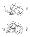
- figure 4 represents the maximum position that can take the work block 10 for which the lower stop 13 of the guide butt 12 bears against the coupling piece 21.
- figure 5 represents the maximum position that can take the work block 10 for which the upper stop 14 of the guide butt 12 bears against the coupling piece 21.
- the support roller 11 of the work block 10 is disposed substantially vertically above the hydraulic support arm 20. This arrangement makes it possible to obtain a very good quality cut but can only be used for work blocks intended for ground work only.
- the work block is attached to the carrier hydraulic arm 20 by means spacing it forward a sufficient distance that allows it to rotate freely in front of said arm.
- the support roller is disposed about 17 cm in front of the plumb with the carrier arm.
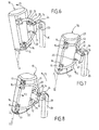
- the implementation of the invention is particularly advantageous when the work block 10 is made to work at height, as shown in FIGS. Figures 6 to 8 .
- the guide butt 12 provides additional mechanical support of the coupling piece 21 against a lateral displacement and avoids deformations thereof, for example at the endpiece.
- the hydraulic support arm 20 is arranged on the side of the carrier vehicle and unfolded so that the work is performed on the side of the vehicle and almost at the cockpit so that the user can easily monitor the work of the machine.
- the arm 20 When working at height, the arm 20 is raised to a position close to the vertical as shown in FIG. figure 6 .
- the carrier vehicle not shown in the drawing is positioned on the right of the arm 20. Accordingly, the figure 6 shows the work block 10 in a position close to the vertical symbolized by the axis ZZ in the drawing, but not having exceeded this position, and the Figures 7 and 8 show said work block 10 in a position beyond the vertical.
- the work block 10 remains free to move clockwise around the pins 16 to fade when the cutting rotor encounters an obstacle.
- the work block 10 is particularly suitable for working at height by the implementation of elastic means ensuring a constant force between the coupling piece 21 and the work block 10 tending to move it away from the coupling piece in the direction of the arrow F3.
- said work block is supported against the coupling piece 21 by the upper stop 14.
- the elastic means are for example constituted by the springs 17 positioned at the front ends of the arms of the coupling piece 21.
- Other embodiments can of course be provided, for example said elastic means may be constituted by interposed springs. between one and / or the other of the low 13 and high stops 14 and the coupling piece 21.
- the work block 10 remains free to move in rotation in the direction of clockwise to avoid an obstacle regardless of its position relative to the vertical.
- the figure 9 shows an alternative embodiment in which the guide butt 112 is more massive than that shown in FIGS. Figures 1 to 8 .
- the guide butt 112 is traversed by a light 121 in which is positioned an element of the coupling piece 221, for example a rod, not visible in the drawing.
- the bottom stops 113 and 114 of the guide butt 112 are constituted by the ends of the light 121.
- the coupling piece 221 comprises two arms 22 connected to each other by a cross member 26 that can bear against the front face of the guide butt 112, the element moving in the light 121 of the buttstock. guide 112 and an end plate 224 carrying a U-shaped endpiece not shown in the drawing.
- the coupling piece 221 bears against the guide butt on both the lateral and front faces of the latter and in the light 121.
- the pins 16 of the embodiment shown in FIGS. Figures 1 to 8 are replaced by an axis 116 extending over the entire width of the work block 10.
- Said axis 116 is for example a torsion bar ensuring the role of the elastic means tending to move the work block 10 of the coupling piece 221 .
- the coupling piece may have a generally triangular shape, the two sides of the triangle constituting the V-arms thereof and being respectively connected to the front of the work block and attachment means to the hydraulic carrier arm.
- the figure 10 represents an alternative embodiment of a work block according to the invention wherein the stops limiting the displacement of the coupling piece 321 are adjustable.
- the position and the hardness of said stops can be adjusted on the one hand so as to control the amplitude of the relative displacement of the coupling piece 321 relative to the guide butt 312 and on the other hand so as to provide a support more or less elastic.
- the guide stick 312 constitutes a hollow housing through which the coupling piece 321 moves in two slots 320 facing the front and the rear of the work block. .
- Each stop 313, 314 is, in this example, constituted by at least one airbag, two such cushions in the embodiment shown in the drawing, arranged on either side of the coupling piece 321, between the ci and the lower and upper faces of the guide butt 312.
- the airbags arranged on the same side of the coupling piece can be inflated identically or not to adapt the elasticity of the abutment they up.
- Said airbags 313, 314 are inflated and deflated by means not shown in the drawing, for example arranged in a housing of the guide stick 312 not occupied by the cushions 313, 314.
- the user of the work block can modify the behavior of the work block.
- the coupling piece 321 is generally arranged between its two extreme positions.
- the cushions 313 When working at height, the cushions 313 are inflated while the cushions 314 are not or are not inflated so that the work block 10 is spaced from the coupling piece 321 by a rotation in the direction of the arrow H.
- airbags makes it possible to maintain a relative displacement capacity of the work block 10 and the coupling piece 321 during work because of their elasticity and thus to dampen the shocks or to filter the vibrations.
- the work block according to the invention may also be equipped with position sensors 18 to detect the positioning of the coupling piece against the lower stop or the upper stop of the guide butt and to provide this information either on a display available to the driver of the vehicle, or to a device for adjusting the position of the hydraulic support arm so that the position of the arm is changed in so that the work block remains free to move in rotation about the axis to move away from the obstacles or follow the inequalities of the ground.
- position sensors 18 to detect the positioning of the coupling piece against the lower stop or the upper stop of the guide butt and to provide this information either on a display available to the driver of the vehicle, or to a device for adjusting the position of the hydraulic support arm so that the position of the arm is changed in so that the work block remains free to move in rotation about the axis to move away from the obstacles or follow the inequalities of the ground.
- the exemplary embodiments of the invention shown in the drawing furthermore have an advantageous structural feature in that it enables the realization of an improved quality cutting work.
- the axis R of the cutting rotor is positioned on the straight line connecting the axis of the support roller 11 to the axis of rotation of the coupling piece 21, 221 on the front of the work block, c ' that is to say the axis of the trunnions 16 or the axis 116.
- This particular arrangement makes it possible to propose a work block whose cutting height varies little when it passes over irregularities of the ground.
Description
La présente invention concerne d'une manière générale les blocs de travail mis en oeuvre pour la coupe et/ou le broyage de végétaux telles que des épareuses utilisées pour entretenir des espaces verts, par exemple des bordures de route, fossés, remblais, en assurant les travaux de fauchage et de débroussaillage.The present invention generally relates to work blocks used for cutting and / or crushing plants such as bulldozers used to maintain green spaces, for example road borders, ditches, embankments, ensuring mowing and brushing.
Ces blocs de travail comportent un rotor portant des outils de coupe travaillant à la manière de fléaux pendant la rotation dudit rotor.These work blocks comprise a rotor carrying cutting tools working in the manner of flails during the rotation of said rotor.
La constitution des outils de coupe liée à la vitesse de rotation du rotor permet d'utiliser de tels blocs de travail de coupe et/ou broyage tant pour couper de l'herbe ou des broussailles, que pour élaguer des arbres ou tailler une haie.The constitution of cutting tools related to the speed of rotation of the rotor makes it possible to use such blocks of cutting and / or grinding work both for cutting grass or brush, for pruning trees or trimming a hedge.
De tels blocs de travail sont portées par un engin de travaux publics ou un tracteur par l'intermédiaire d'un bras usuellement disposé à l'arrière du véhicule porteur. Ledit bras s'étend globalement perpendiculairement à la direction de déplacement dudit véhicule afin que le bloc de travail soit positionné sur le côté du véhicule au cours du travail. Pour un travail de fauchage au sol, le rotor du bloc de travail est positionné dans un plan horizontal globalement parallèle au sol tandis que pour un travail de taille d'une haie, le bloc de travail est soulevé par le bras et ledit rotor est dans un plan globalement vertical.Such work blocks are carried by a public works machine or a tractor by means of an arm usually disposed at the rear of the carrier vehicle. Said arm extends generally perpendicular to the direction of movement of said vehicle so that the work block is positioned on the side of the vehicle during work. For a mowing work on the ground, the rotor of the work block is positioned in a horizontal plane generally parallel to the ground while for a size work of a hedge, the work block is raised by the arm and said rotor is in a globally vertical plan.
Il a été proposé dans le
Par cette disposition représentée à la
Comme visible au dessin, une pièce d'attelage E est interposée entre un arbre horizontal D porté par le bras B et le bloc de travail A. Cette pièce d'attelage E est globalement constituée d'une poutre 1 et de deux bras 2 disposés en V. La poutre 1 est destinée à être positionnée dans un fer en U 5 porté par l'arbre horizontal D pour atteler le bloc de travail A au bras B. Les extrémités avant des bras 2 sont accrochées sur des chapes 3 positionnées à l'avant du bloc de travail A au moyen de tourillons 4.As visible in the drawing, a coupling piece E is interposed between a horizontal shaft D carried by the arm B and the working block A. This coupling piece E is generally composed of a
Au cours du travail de coupe, le bloc de travail A est tiré par les bras 2 et mobile en rotation autour de l'axe XX défini par les tourillons 4.During the cutting work, the work block A is pulled by the
Lors de travaux de débroussaillage ou de taille en hauteur, il était prévu dans le brevet antérieur d'immobiliser le bloc de travail par rapport au bras B en démontant la pièce d'attelage E et en attelant la bloc de travail A au fer en U 5 du bras B par la poutre 6 (
Il a été constaté que les utilisateurs de ces blocs de travail ne modifient pas le montage dudit bloc de travail sur le bras lorsqu'ils passent d'un travail au sol à un travail en hauteur et ne procèdent donc pas au démontage de la pièce d'attelage.It has been found that the users of these work blocks do not modify the mounting of said work block on the arm when they move from a ground work to a work at height and therefore do not dismantle the workpiece. 'coupling.
Dans ce cas, le bloc de travail attelé au bras par la pièce d'attelage E est libre en rotation par rapport à la pièce d'attelage. Le débattement du bloc de travail autour de l'axe XX est alors pratiquement imprévisible puisqu'il dépend de l'inclinaison du bloc de travail, de l'inclinaison du bras hydraulique, de la forme du terrain et de la présence d'obstacles tels que de grosses branches que le bloc de travail ne peut couper. En conséquence, le travail n'est pas de bonne qualité. De plus, les changements de position du bloc de travail sont souvent brusques et modifient de manière importante la répartition des masses sur le véhicule porteur ce qui peut provoquer le renversement de celui-ci s'il est déjà soumis à un déséquilibre du à des inégalités du terrain.In this case, the work block coupled to the arm by the coupling piece E is free to rotate relative to the coupling piece. The movement of the work block around the axis XX is then practically unpredictable since it depends on the inclination of the work block, the inclination of the hydraulic arm, the shape of the ground and the presence of obstacles such as only big branches that the work block can not cut. As a result, the work is not of good quality. In addition, changes in the position of the work block are often abrupt and significantly alter the distribution of masses on the carrier vehicle which can cause the reversal of it if it is already subject to an imbalance due to uneven terrain.
Un autre bloc de travail qui correspond au préambule de la revendication 1 est divulgué dans la demande de brevet
La présente invention a en conséquence pour objet d'apporter un perfectionnement aux blocs de travail de coupe et/ou broyage de végétaux rendant possible leur utilisation dans de bonnes conditions que ce soit au sol ou en hauteur sans nécessiter la modification de l'attelage dudit bloc de travail au bras porteur.The object of the present invention is therefore to provide an improvement to the work blocks for cutting and / or crushing plants making it possible to use them under good conditions whether on the ground or at the height without requiring the modification of the hitch of said working block on the support arm.
A cet effet, selon l'invention, le bloc de travail de coupe et/ou broyage de végétaux destiné à être porté par un véhicule porteur par l'intermédiaire d'un bras et comportant une pièce d'attelage montée libre en rotation sur son avant, est caractérisé en ce qu'il porte une crosse de guidage de ladite pièce d'attelage et des butées basse et haute de limitation du déplacement en rotation de ladite pièce d'attelage.For this purpose, according to the invention, the plant cutting and / or grinding work block intended to be carried by a carrier vehicle via an arm and having a coupling piece mounted free to rotate on its before, is characterized in that it carries a guide butt of said coupling piece and low and high stops limiting the rotational movement of said coupling piece.
Comme on pourra le constater à la lecture de la description qui va suivre, un tel montage selon l'invention permet d'obtenir une discontinuité de l'attelage du bloc de travail au véhicule porteur au niveau de la crosse de guidage, car les seules articulations amenées à travailler sont celles entre l'extrémité avant de la pièce d'attelage et le bloc de travail.As can be seen from reading the description which follows, such an assembly according to the invention makes it possible to obtain a discontinuity of the coupling of the work block to the carrier vehicle at the level of the guide butt, because the only articulations brought to work are those between the front end of the coupling piece and the work block.
Ainsi, les efforts, déplacements et trépidations subis par le bloc de travail pendant le travail ne sont pas transmis au bras porteur, au véhicule et au conducteur de celui-ci. Il en découle un meilleur confort de travail pour le conducteur et une diminution importante de la maintenance à réaliser sur le matériel.Thus, the efforts, movements and trepidations suffered by the work block during work are not transmitted to the support arm, the vehicle and the driver of the latter. This results in a better working comfort for the driver and a significant reduction in the maintenance to be performed on the equipment.
Dans les montages connus, lorsque le bloc de travail rencontre un obstacle, le bras porteur s'écarte vers l'arrière du véhicule porteur et le conducteur doit le ramener vers l'avant, dans la position de travail. Le montage suivant l'invention permettant un déplacement vertical du bloc de travail pour surmonter un obstacle, les écarts vers l'arrière du bras porteur deviennent très rares ce qui facilite le travail du conducteur et permet une avance plus rapide.In known assemblies, when the work block encounters an obstacle, the support arm deviates towards the rear of the carrier vehicle and the driver must bring it forward, in the working position. The assembly according to the invention allows a vertical displacement of the work block to overcome an obstacle, the rearward deviations of the support arm become very rare which facilitates the work of the driver and allows a faster advance.
Un autre avantage fournit par le montage suivant l'invention tient au fait que le bloc de travail suit beaucoup mieux le profil du terrain puisqu'il n'est plaqué au sol que par son propre poids car le poids du bras ne lui est plus appliqué.Another advantage provided by the assembly according to the invention lies in the fact that the work block follows the profile of the ground much better since it is only placed on the ground by its own weight because the weight of the arm is no longer applied to it. .
Le bloc de travail selon l'invention est encore remarquable en ce que :
- les butées basse et haute de limitation du déplacement en rotation de ladite pièce d'attelage sont portées par la crosse de guidage,
- la pièce d'attelage est en appui contre la crosse de guidage,
- des moyens élastiques assurent un effort constant entre la pièce d'attelage et la machine tendant à écarter ladite machine de ladite pièce d'attelage,
- les butées de limitation du déplacement de la pièce d'attelage sont réglables en position et en dureté,
- la pièce d'attelage est en appui contre la crosse de guidage par des patins,
- la crosse de guidage est traversée par une lumière dans laquelle est positionné un élément de la pièce d'attelage, les extrémités de ladite lumière constituant les butées basse et haute de limitation du déplacement en rotation de ladite pièce d'attelage,
- la pièce d'attelage comporte deux bras raccordés l'un à l'autre par une traverse en appui contre la face avant de la crosse de guidage et par l'élément se déplaçant dans la lumière de la crosse de guidage,
- il est équipé de capteurs de position détectant le positionnement de la pièce d'attelage contre la butée basse ou la butée haute,
- il est équipé d'un rouleau d'appui et d'un rotor de coupe, et, l'axe dudit rouleau d'appui, l'axe de rotation de la pièce d'attelage et l'axe du rotor de coupe sont alignés.
- the low and high stops for limiting the rotational displacement of said coupling piece are carried by the guide butt,
- the coupling piece bears against the guide butt,
- elastic means ensure a constant force between the coupling piece and the machine tending to separate said machine from said coupling piece,
- the limits for limiting the displacement of the coupling piece are adjustable in position and in hardness,
- the coupling piece bears against the guide butt by pads,
- the guide butt is traversed by a light in which is positioned an element of the coupling piece, the ends of said light constituting the low and high stops for limiting the rotational movement of said coupling piece,
- the coupling part comprises two arms connected to each other by a crosspiece resting against the front face of the guide butt and by the element moving in the guide rod,
- it is equipped with position sensors detecting the positioning of the coupling piece against the lower stop or the upper stop,
- it is equipped with a support roller and a cutting rotor, and, the axis of said support roller, the axis of rotation of the coupling piece and the axis of the cutting rotor are aligned .
L'invention sera mieux comprise grâce à la description qui va suivre donnée à titre d'exemple non limitatif en référence aux dessins annexés dans lesquels :
- les
figures 1 et 2 montrent un bloc de travail de l'art antérieur attelé à un bras hydraulique porteur en vue d'un travail respectivement au sol et en hauteur, - la
figure 3 représente schématiquement un bloc de travail suivant une première variante de réalisation de l'invention travaillant au sol, sur un sol plat, - les
figures 4 et 5 montrent le bloc de travail de lafigure 3 lors d'un passage sur un accident de terrain, respectivement une bosse et un creux, - la
figure 6 montre le bloc de travail de lafigure 3 travaillant en hauteur, en n'ayant pas atteint sa position verticale, - la
figure 7 montre le bloc de travail de lafigure 3 travaillant en hauteur, incliné au-delà de sa position verticale, - la
figure 8 montre un bloc de travail suivant une variante de réalisation du bloc de travail desfigures 3 à 7 dans la même position qu'à lafigure 7 , - la
figure 9 montre un bloc de travail suivant une seconde variante de réalisation de l'invention, - la
figure 10 est une vue schématique avec coupe partielle, d'un bloc de travail suivant une variante de réalisation de l'invention.
- the
Figures 1 and 2 show a work block of the prior art coupled to a hydraulic carrier arm for working respectively on the ground and height, - the
figure 3 schematically represents a work block according to a first embodiment of the invention working on the ground, on flat ground, - the
Figures 4 and 5 show the work block of thefigure 3 during a passage on an accident of ground, respectively a hump and a hollow, - the
figure 6 shows the work block of thefigure 3 working in height, having not reached its vertical position, - the
figure 7 shows the work block of thefigure 3 working in height, inclined beyond its vertical position, - the
figure 8 shows a work block according to an alternative embodiment of the work block ofFigures 3 to 7 in the same position as in thefigure 7 , - the
figure 9 shows a work block according to a second embodiment of the invention, - the
figure 10 is a schematic view in partial section of a work block according to an alternative embodiment of the invention.
Comme visible au dessin,
Ladite pièce d'attelage 21 est composée d'au moins un bras 22 et d'un embout 24, en U dans l'exemple représenté au dessin, auquel est fixé l'arbre 23.Said
L'extrémité avant de chaque bras 22 est montée libre en rotation sur une chape 15 disposée à l'avant du bloc de travail 10 au moyen d'un tourillon 16.The front end of each
Suivant l'invention, le bloc de travail 10 porte une crosse de guidage 12 de ladite pièce d'attelage 21. Ladite crosse de guidage 12 est disposée sur la face supérieure du capot dudit bloc de travail 10, s'étend globalement perpendiculairement audit capot et présente une forme générale arquée.According to the invention, the
Dans l'exemple de réalisation représenté au dessin, et mieux visible aux
Le déplacement de la pièce d'attelage 21 le long de la crosse de guidage 12 est limité par des butées basse 13 et haute 14, disposées sur la crosse de guidage 12 dans les exemples de réalisations représentés au dessin.The displacement of the
De manière préférée, les patins 25 de la pièce d'attelage 21 sont en appui contre les deux faces latérales de ladite crosse de guidage 12 afin d'éviter un déplacement latéral du bloc de travail 10.Preferably, the
Lorsque le bloc de travail 10 travaille sur un sol S0 plat,
Comme on peut le remarquer, pour laisser la possibilité d'améliorer la capacité du bloc de travail à travailler en hauteur comme cela sera décrit plus loin, et dans la mesure où ceux-ci ne se sont pas révélés totalement indispensables, les moyens élastiques 7 tels que ceux prévus dans l'art antérieur (
Si au cours du travail, le rouleau d'appui 11 est sur une bosse S1, le bloc de travail 10 est entraîné en rotation dans le sens des aiguilles d'une montre autour de l'axe défini par les tourillons 16 et la butée basse 13 est rapprochée de la pièce d'attelage 21. La
A l'inverse, lorsque au cours du travail, le rouleau d'appui 11 est dans un creux S2, le bloc de travail 10 est entraîné en rotation dans le sens inverse des aiguilles d'une montre autour de l'axe défini par les tourillons 16 et la butée haute 14 est rapprochée de la pièce d'attelage 21. La
Comme visible aux
En effet, lors d'un travail en hauteur la rotation du bloc de travail est limitée par la butée de celui-ci contre le bras hydraulique porteur 20.Indeed, when working at height the rotation of the work block is limited by the abutment thereof against the
C'est pourquoi, comme visible aux
La mise en oeuvre de l'invention est particulièrement intéressante lorsque le bloc de travail 10 est amené à travailler en hauteur, comme représenté aux
De manière connue en soi, le bras hydraulique porteur 20 est disposé sur le côté du véhicule porteur et déplié afin que le travail soit effectué sur le côté du véhicule et pratiquement au niveau de la cabine de pilotage de sorte que l'utilisateur puisse facilement surveiller le travail de la machine.In a manner known per se, the
Lors d'un travail en hauteur, le bras 20 est relevé dans une position proche de la verticale comme représenté à la
Le véhicule porteur non représenté au dessin est positionné sur la droite du bras 20. En conséquence, la
Dans la position représentée à la
Au cours d'un tel déplacement du à son poids dans la direction F1, le bloc de travail 10 se déplace en rotation dans le sens inverse des aiguilles d'une montre autour des tourillons 16 et la crosse de guidage 12 glisse le long de la pièce d'attelage 21 jusqu'à être en appui contre celle-ci par la butée haute 14.During such displacement due to its weight in the direction F1, the
Toutefois, le bloc de travail 10 reste libre de se déplacer dans le sens des aiguilles d'une montre autour des tourillons 16 en vue de s'effacer lorsque le rotor de coupe rencontre un obstacle.However, the
Dans une telle position proche de la verticale du bloc de travail 10, la mise en oeuvre suivant l'invention d'une crosse de guidage 12 munie de butées basse 13 et haute 14 permet alors de limiter la rotation due à son poids du bloc de travail 10 tout en lui laissant la possibilité de s'effacer lorsqu'il rencontre un obstacle.In such a position close to the vertical of the
Lorsque le bloc de travail 10 est positionné au-delà de sa position verticale,
Dans la variante de réalisation de la
Les moyens élastiques sont par exemple constitués par les ressorts 17 positionnés aux extrémités avant des bras de la pièce d'attelage 21. D'autres réalisations peuvent bien entendu être prévues, à titre d'exemple lesdits moyens élastiques peuvent être constitués par des ressorts interposés entre l'une et/ou l'autre des butées basse 13 et haute 14 et la pièce d'attelage 21.The elastic means are for example constituted by the
Dans cette variante de réalisation, le bloc de travail 10 reste libre de se déplacer en rotation dans le sens des aiguilles d'une montre afin d'éviter un obstacle quelle que soit sa position par rapport à la verticale.In this embodiment, the
Il convient de noter que l'effort qui doit être appliqué par de tels moyens élastiques 17 lorsque le bloc de travail 10 travaille en hauteur n'est pas important et qu'en conséquence cet effort n'est pas gênant lors d'un travail au sol.It should be noted that the force that must be applied by such
La
Dans l'exemple de réalisation représenté au dessin, la crosse de guidage 112 est traversée par une lumière 121 dans laquelle est positionné un élément de la pièce d'attelage 221, par exemple une tige, non visible au dessin. Les butées basse 113 et haute 114 de la crosse de guidage 112 sont constituées par les extrémités de la lumière 121.In the embodiment shown in the drawing, the
La pièce d'attelage 221 comporte deux bras 22 raccordés l'un à l'autre par une traverse 26 pouvant être en appui contre la face avant de la crosse de guidage 112, l'élément se déplaçant dans la lumière 121 de la crosse de guidage 112 et une plaque d'extrémité 224 portant un embout en U non représenté au dessin.The
La pièce d'attelage 221 est en appui contre la crosse de guidage à la fois sur les faces latérales et frontale de celle-ci et dans la lumière 121.The
Les tourillons 16 de la réalisation représentée aux
Suivant une forme de réalisation non représentée au dessin, la pièce d'attelage peut avoir une forme globalement triangulaire, les deux côtés du triangle constituant les bras en V de celle-ci et étant raccordés respectivement à l'avant du bloc de travail et à des moyens d'accrochage au bras hydraulique porteur.According to an embodiment not shown in the drawing, the coupling piece may have a generally triangular shape, the two sides of the triangle constituting the V-arms thereof and being respectively connected to the front of the work block and attachment means to the hydraulic carrier arm.
La
La position et la dureté desdites butées peuvent être réglées d'une part de manière à contrôler l'amplitude du déplacement relatif de la pièce d'attelage 321 par rapport à la crosse de guidage 312 et d'autre part de manière à fournir un appui plus ou moins élastique.The position and the hardness of said stops can be adjusted on the one hand so as to control the amplitude of the relative displacement of the
A cet effet, différents moyens de réalisation desdites butées peuvent être mis en oeuvre tels que des vérins qu'ils soient hydrauliques ou électriques, des coussins gonflables,...For this purpose, different means of making said stops can be implemented such as cylinders that are hydraulic or electric, air bags, ...
Dans la forme de réalisation représentée au dessin, la crosse de guidage 312 constitue un boîtier creux à travers lequel se déplace la pièce d'attelage 321 positionnée dans deux fentes 320 faisant face à l'avant et à l'arrière du bloc de travail 10.In the embodiment shown in the drawing, the
Chaque butée 313, 314 est, dans cet exemple, constituée par au moins un coussin gonflable, deux tels coussins dans l'exemple de réalisation représenté au dessin, disposés de part et d'autre de la pièce d'attelage 321, entre celle-ci et les faces inférieure et supérieure de la crosse de guidage 312. Les coussins gonflables disposés d'un même côté de la pièce d'attelage peuvent être gonflés de manière identique ou non afin d'adapter l'élasticité de la butée qu'ils constituent.Each
Lesdits coussins gonflables 313, 314 sont gonflés et dégonflés par des moyens non représentés au dessin, par exemple disposés dans un logement de la crosse de guidage 312 non occupé par les coussins 313, 314.Said
En modifiant le gonflage desdits coussins 313, 314, l'utilisateur du bloc de travail peut modifier le comportement du bloc de travail.By modifying the inflation of said
En gonflant tous les coussins 313 et 314 constituant les butées, on fixe une position relative du bloc de travail 10 et de la pièce d'attelage 321. Dans l'exemple représenté au dessin, la pièce d'attelage 321 est globalement disposée entre ses deux positions extrêmes.By inflating all the
En dégonflant tous les coussins 313 et 314, le déplacement en rotation du bloc de travail 10 par rapport à la pièce d'attelage 321 est libre, les coussins constituant des butées de fin course.By deflating all the
Lors d'un travail en hauteur, les coussins 313 sont gonflés tandis que les coussins 314 ne sont pas ou sont peu gonflés de sorte que le bloc de travail 10 soit écarté de la pièce d'attelage 321 par une rotation dans le sens de la flèche H.When working at height, the cushions 313 are inflated while the
Inversement, lors du transport du bloc de travail, seuls les coussins 314 sont gonflés de manière à rapprocher le bloc de travail 10 de la pièce d'attelage 321 par une rotation dans le sens de la flèche B.Conversely, during transport of the work block, only the
La mise en oeuvre de coussins gonflables permet de conserver une capacité de déplacement relatif du bloc de travail 10 et de la pièce d'attelage 321 au cours du travail du fait de leur élasticité et donc d'amortir les chocs ou de filtrer les vibrations.The use of airbags makes it possible to maintain a relative displacement capacity of the
En variante, le bloc de travail selon l'invention peut également être équipé de capteurs de position 18 afin de détecter le positionnement de la pièce d'attelage contre la butée basse ou la butée haute de la crosse de guidage et de fournir cette information soit sur un afficheur à la disposition du conducteur du véhicule, soit à un dispositif de réglage de la position du bras hydraulique porteur afin que la position du bras soit modifiée en sorte que le bloc de travail reste libre de se déplacer en rotation autour de l'axe pour s'écarter devant les obstacles ou suivre les inégalités du sol.Alternatively, the work block according to the invention may also be equipped with
Les exemples de réalisation de l'invention représentés au dessin présentent de plus une caractéristique structurelle avantageuse en ce qu'elle permet la réalisation d'un travail de coupe de qualité améliorée.The exemplary embodiments of the invention shown in the drawing furthermore have an advantageous structural feature in that it enables the realization of an improved quality cutting work.
Comme matérialisé sur les
Cette disposition particulière permet de proposer un bloc de travail dont la hauteur de coupe varie peu lors de son passage sur des irrégularités du terrain.This particular arrangement makes it possible to propose a work block whose cutting height varies little when it passes over irregularities of the ground.
Claims (10)
- Plant cutting and/or crushing work block designed to be carried by a carrying vehicle by means of an arm and comprising a coupling part mounted free in rotation on its front, characterised by the fact that it carries a guide unit (12, 112, 312) for said coupling block (21, 221, 321) and lower (13, 113, 313) and upper (14, 114, 314) stops limiting the rotational movement of said coupling part (21, 221, 321).
- Work block according to claim 1, characterised by the fact that the lower (13, 113, 313) and upper (14, 114, 314) stops limiting the rotational movement of said coupling part (21, 221, 321) are carried by the guide unit (12, 112, 312).
- Work block according to claim 1 or according to claim 2, characterised by the coupling part (21, 221, 321) bearing against the guide unit (12, 112, 312).
- Work block according to any one of the above claims, characterised by the elastic means (17, 116) applying a constant force between the coupling part and the machine tending to move said machine away from said coupling part.
- Work block according to any one of the above claims, characterised by the fact that the stops (313, 314) limiting the movement of the coupling part (321) are adjustable in position and in hardness.
- Work block according to any one of the above claims, characterised by the coupling part (21) bearing against the guide unit (12) via skids (25).
- Work block according to any one of the above claims 1 to 4, characterised by the fact that the guide unit (112) comprises an opening (121) in which an element of the coupling part (221) is positioned, the ends of said opening (121) constituting the lower (113) and upper (114) stops limiting the rotational movement of said coupling part (221).
- Work block according to claim 7, characterised by the coupling part (221) comprising two arms (220) connected to each other by a crosspiece (26) bearing against the front face of the guide unit (112) and by the element moving in the opening (121) of the guide unit (112).
- Work block according to any one of the above claims, characterised by its being equipped with pressure sensors (18) detecting the positioning of the coupling part against the lower stop or the upper stop.
- Work block according to any one of the claims, equipped with a bearing roller (11) and a cutting rotor, characterised by the axis of said bearing roller (11), the axis of rotation of the coupling part (21, 221, 321) and the axis of the cutting rotor being aligned.
Applications Claiming Priority (1)
| Application Number | Priority Date | Filing Date | Title |
|---|---|---|---|
| FR0801583A FR2928812B1 (en) | 2008-03-21 | 2008-03-21 | WORKING BLOCK FOR CUTTING AND / OR MILLING PLANTS TO BE CARRIED BY A CARRIER VEHICLE THROUGH AN ARM |
Publications (2)
| Publication Number | Publication Date |
|---|---|
| EP2103202A1 EP2103202A1 (en) | 2009-09-23 |
| EP2103202B1 true EP2103202B1 (en) | 2013-04-03 |
Family
ID=39777252
Family Applications (1)
| Application Number | Title | Priority Date | Filing Date |
|---|---|---|---|
| EP20090305214 Not-in-force EP2103202B1 (en) | 2008-03-21 | 2009-03-09 | Work block for chopping and/or grinding vegetables designed to be carried by a carrier vehicle by means of an arm |
Country Status (2)
| Country | Link |
|---|---|
| EP (1) | EP2103202B1 (en) |
| FR (1) | FR2928812B1 (en) |
Family Cites Families (5)
| Publication number | Priority date | Publication date | Assignee | Title |
|---|---|---|---|---|
| GB8715779D0 (en) * | 1987-07-04 | 1987-08-12 | Econ Group Ltd | Mower/hedger attachment |
| US5537808A (en) * | 1994-04-29 | 1996-07-23 | Dallman; Jammie J. | Control assembly for a brush cutting machine |
| FR2762962B1 (en) * | 1997-05-07 | 1999-07-23 | Noremat | IMPROVEMENTS ON HORIZONTAL AXIS ROTOR CUTTING DEVICES |
| FR2774551B1 (en) * | 1998-02-09 | 2000-04-28 | Noremat | CUTTING TOOL FOR BEING CARRIED OUT OF AN ARTICULATED ARM MOUNTED ON A VEHICLE |
| FR2866781B1 (en) * | 2004-03-01 | 2006-06-02 | Noremat | DEVICE FOR THE SUSPENSION OF A CUTTING OR GRINDING TOOL TO A BEARING ELEMNT HAVING MEANS FOR CONTROLLING ITS LOWERING AND / OR LIFTING MOTION |
-
2008
- 2008-03-21 FR FR0801583A patent/FR2928812B1/en not_active Expired - Fee Related
-
2009
- 2009-03-09 EP EP20090305214 patent/EP2103202B1/en not_active Not-in-force
Also Published As
| Publication number | Publication date |
|---|---|
| FR2928812B1 (en) | 2011-09-02 |
| FR2928812A1 (en) | 2009-09-25 |
| EP2103202A1 (en) | 2009-09-23 |
Similar Documents
| Publication | Publication Date | Title |
|---|---|---|
| EP0211785B1 (en) | Mower | |
| CA2535238C (en) | Agricultural machine for cutting products | |
| EP0741960A1 (en) | A mowing machine having a harvesting mechanism with a lightening device adjustable by remote control | |
| EP2448808B1 (en) | Self-propelled high-clearance vehicle | |
| EP3071008B1 (en) | Agricultural machine, in particular machine for harvesting plant matter, comprising two driven working units that are articulated on a single lateral arm | |
| CH640694A5 (en) | DEVICE FOR CUTTING GRASS UNDER BARRIERS. | |
| CA2629914A1 (en) | Agricultural implement comprising an improved hitch structure | |
| EP0945551B1 (en) | Sweeping device for utility vehicle | |
| FR2530399A1 (en) | ARTICULATED VEHICLE, IN PARTICULAR IN THE FORM OF AN AGRICULTURAL MACHINE | |
| FR2794934A1 (en) | AGRICULTURAL MACHINE OF THE MOWER OR MOWER CONDITIONER TYPE COMPRISING A SHOCK ABSORBER | |
| EP3713391B1 (en) | Agricultural machine provided with a simplified safety system enabling a tool or group of tools connected to a hitching support by a support arm to carry out a safety movement | |
| FR3012940A1 (en) | AGRICULTURAL LOADING TRAILER, EQUIPPED WITH AT LEAST ONE POSTURE SIDE WHEEL WITH INDEPENDENT SUSPENSION OF SIDE GAUGE WHEELS | |
| EP2103202B1 (en) | Work block for chopping and/or grinding vegetables designed to be carried by a carrier vehicle by means of an arm | |
| FR2977123A1 (en) | Plant cutting and crushing equipment for use with towing vehicle to maintain ground e.g. roadside, has force exerting unit whose upward force is adjusted to compensate part of downward force exerted by weight of distal arm | |
| FR3031069A1 (en) | VEHICLE EQUIPPED WITH SPEED CORRECTION AND STEERING CONTROL SYSTEMS FOR A WHEEL ASSEMBLY, AND SUCH A SYSTEM | |
| FR2948850A1 (en) | Plant cutting/crushing equipment for use in towing vehicle, has radial notches receiving obstacle e.g. tree trunks, during advancement of towing vehicle causing rotation of cutting/crushing head to circumvent obstacle | |
| FR3052328A1 (en) | AGRICULTURAL MACHINE, IN PARTICULAR MOWER OR MILLING MACHINE, COMPRISING A FOLDING WORKING GROUP AND A PULLED TRAINING ASSEMBLY | |
| FR2800972A1 (en) | Apparatus, for reaping vegetables, comprises first and second frames, with profile of first frame attached to profile of second frame using links | |
| EP1319761A1 (en) | Ditch cutting and/or cleaning apparatus and vehicle equipped with such an apparatus | |
| EP0292372B1 (en) | Mower with a cutting apparatus mounted on a supporting arm | |
| EP2179640A1 (en) | Machine for cutting plants | |
| EP3108730B1 (en) | Mounted agricultural machine with a group of tools that can be offset laterally | |
| FR2883698A1 (en) | Tool e.g. auger, coupling device for e.g. quad bike, has rod positioning plate relative to arms for placing plate relative to arms along pivoting course of arms, or for pivoting plate relative to arms for translating plate along course | |
| FR2818606A1 (en) | Tracked vehicle for use on rough ground has track supporting wheels on beam in two articulated sections | |
| FR2800400A1 (en) | MULTIFUNCTIONAL MOTOR VEHICLE FOR THE MAINTENANCE OF GREEN AREAS |
Legal Events
| Date | Code | Title | Description |
|---|---|---|---|
| PUAI | Public reference made under article 153(3) epc to a published international application that has entered the european phase |
Free format text: ORIGINAL CODE: 0009012 |
|
| AK | Designated contracting states |
Kind code of ref document: A1 Designated state(s): AT BE BG CH CY CZ DE DK EE ES FI FR GB GR HR HU IE IS IT LI LT LU LV MC MK MT NL NO PL PT RO SE SI SK TR |
|
| AX | Request for extension of the european patent |
Extension state: AL BA RS |
|
| 17P | Request for examination filed |
Effective date: 20100217 |
|
| 17Q | First examination report despatched |
Effective date: 20100312 |
|
| AKX | Designation fees paid |
Designated state(s): BE DE FR GB IT NL |
|
| GRAP | Despatch of communication of intention to grant a patent |
Free format text: ORIGINAL CODE: EPIDOSNIGR1 |
|
| GRAS | Grant fee paid |
Free format text: ORIGINAL CODE: EPIDOSNIGR3 |
|
| GRAA | (expected) grant |
Free format text: ORIGINAL CODE: 0009210 |
|
| AK | Designated contracting states |
Kind code of ref document: B1 Designated state(s): BE DE FR GB IT NL |
|
| REG | Reference to a national code |
Ref country code: GB Ref legal event code: FG4D Free format text: NOT ENGLISH |
|
| REG | Reference to a national code |
Ref country code: DE Ref legal event code: R096 Ref document number: 602009014610 Country of ref document: DE Effective date: 20130529 |
|
| REG | Reference to a national code |
Ref country code: NL Ref legal event code: VDEP Effective date: 20130403 |
|
| PG25 | Lapsed in a contracting state [announced via postgrant information from national office to epo] |
Ref country code: NL Free format text: LAPSE BECAUSE OF FAILURE TO SUBMIT A TRANSLATION OF THE DESCRIPTION OR TO PAY THE FEE WITHIN THE PRESCRIBED TIME-LIMIT Effective date: 20130403 |
|
| PLBE | No opposition filed within time limit |
Free format text: ORIGINAL CODE: 0009261 |
|
| STAA | Information on the status of an ep patent application or granted ep patent |
Free format text: STATUS: NO OPPOSITION FILED WITHIN TIME LIMIT |
|
| PG25 | Lapsed in a contracting state [announced via postgrant information from national office to epo] |
Ref country code: IT Free format text: LAPSE BECAUSE OF FAILURE TO SUBMIT A TRANSLATION OF THE DESCRIPTION OR TO PAY THE FEE WITHIN THE PRESCRIBED TIME-LIMIT Effective date: 20130403 |
|
| 26N | No opposition filed |
Effective date: 20140106 |
|
| REG | Reference to a national code |
Ref country code: DE Ref legal event code: R097 Ref document number: 602009014610 Country of ref document: DE Effective date: 20140106 |
|
| REG | Reference to a national code |
Ref country code: DE Ref legal event code: R119 Ref document number: 602009014610 Country of ref document: DE |
|
| GBPC | Gb: european patent ceased through non-payment of renewal fee |
Effective date: 20140309 |
|
| REG | Reference to a national code |
Ref country code: DE Ref legal event code: R119 Ref document number: 602009014610 Country of ref document: DE Effective date: 20141001 |
|
| PG25 | Lapsed in a contracting state [announced via postgrant information from national office to epo] |
Ref country code: DE Free format text: LAPSE BECAUSE OF NON-PAYMENT OF DUE FEES Effective date: 20141001 Ref country code: GB Free format text: LAPSE BECAUSE OF NON-PAYMENT OF DUE FEES Effective date: 20140309 |
|
| REG | Reference to a national code |
Ref country code: FR Ref legal event code: PLFP Year of fee payment: 8 |
|
| REG | Reference to a national code |
Ref country code: FR Ref legal event code: PLFP Year of fee payment: 9 |
|
| PGFP | Annual fee paid to national office [announced via postgrant information from national office to epo] |
Ref country code: FR Payment date: 20170331 Year of fee payment: 9 |
|
| PG25 | Lapsed in a contracting state [announced via postgrant information from national office to epo] |
Ref country code: BE Free format text: LAPSE BECAUSE OF NON-PAYMENT OF DUE FEES Effective date: 20140331 |
|
| PG25 | Lapsed in a contracting state [announced via postgrant information from national office to epo] |
Ref country code: FR Free format text: LAPSE BECAUSE OF NON-PAYMENT OF DUE FEES Effective date: 20180331 |