EP2103098B1 - Konferenz, bei der die mischung durch eine wiedergabeeinrichtung zeitgesteuert wird - Google Patents
Konferenz, bei der die mischung durch eine wiedergabeeinrichtung zeitgesteuert wird Download PDFInfo
- Publication number
- EP2103098B1 EP2103098B1 EP06841205A EP06841205A EP2103098B1 EP 2103098 B1 EP2103098 B1 EP 2103098B1 EP 06841205 A EP06841205 A EP 06841205A EP 06841205 A EP06841205 A EP 06841205A EP 2103098 B1 EP2103098 B1 EP 2103098B1
- Authority
- EP
- European Patent Office
- Prior art keywords
- audio data
- conference
- mixer
- data stream
- telecommunications terminal
- Prior art date
- Legal status (The legal status is an assumption and is not a legal conclusion. Google has not performed a legal analysis and makes no representation as to the accuracy of the status listed.)
- Active
Links
Images


Classifications
-
- H—ELECTRICITY
- H04—ELECTRIC COMMUNICATION TECHNIQUE
- H04M—TELEPHONIC COMMUNICATION
- H04M3/00—Automatic or semi-automatic exchanges
- H04M3/42—Systems providing special services or facilities to subscribers
- H04M3/56—Arrangements for connecting several subscribers to a common circuit, i.e. affording conference facilities
- H04M3/562—Arrangements for connecting several subscribers to a common circuit, i.e. affording conference facilities where the conference facilities are distributed
-
- H—ELECTRICITY
- H04—ELECTRIC COMMUNICATION TECHNIQUE
- H04M—TELEPHONIC COMMUNICATION
- H04M3/00—Automatic or semi-automatic exchanges
- H04M3/42—Systems providing special services or facilities to subscribers
- H04M3/56—Arrangements for connecting several subscribers to a common circuit, i.e. affording conference facilities
- H04M3/568—Arrangements for connecting several subscribers to a common circuit, i.e. affording conference facilities audio processing specific to telephonic conferencing, e.g. spatial distribution, mixing of participants
-
- H—ELECTRICITY
- H04—ELECTRIC COMMUNICATION TECHNIQUE
- H04N—PICTORIAL COMMUNICATION, e.g. TELEVISION
- H04N21/00—Selective content distribution, e.g. interactive television or video on demand [VOD]
- H04N21/40—Client devices specifically adapted for the reception of or interaction with content, e.g. set-top-box [STB]; Operations thereof
- H04N21/47—End-user applications
- H04N21/478—Supplemental services, e.g. displaying phone caller identification, shopping application
- H04N21/4788—Supplemental services, e.g. displaying phone caller identification, shopping application communicating with other users, e.g. chatting
-
- H—ELECTRICITY
- H04—ELECTRIC COMMUNICATION TECHNIQUE
- H04N—PICTORIAL COMMUNICATION, e.g. TELEVISION
- H04N7/00—Television systems
- H04N7/14—Systems for two-way working
- H04N7/15—Conference systems
- H04N7/157—Conference systems defining a virtual conference space and using avatars or agents
Definitions
- the present invention generally relates to the field of telecommunications, and particularly to audio or audio/video conferencing. Specifically, the invention concerns a telecommunications terminal hosting an audio, or an audio/video conference mixer.
- VoIP Voice over internet Protocol
- VDC video communication
- peers Most often, services of this kind involve two intercommunicating peers, but an interesting extension is represented by "virtual" audio and/or video conferencing, where more than two parties (“peers”) are involved in the audio and/or video communication session, and can interact with each other by listening/speaking and/or viewing.
- conference mixers gathers the audio and/or video contents generated by local capturing devices (microphones, videocameras) provided in user terminals (the “endpoints") at each of the conferencing parties, properly mixes the gathered audio and/or video contents, and redistributes the mixed contents to every party to the virtual conference.
- local capturing devices microphones, videocameras
- endpoints user terminals
- conference mixers are apparatuses distinct and remote from the endpoints of the conferencing parties, being core network apparatuses (referred to as "Master Control Units", shortly MCUs).
- a packet data terminal is disclosed, particularly a personal computer, personal digital assistant, telephone, mobile radiotelephone, network access device, Internet peripheral and the like, which initiates, coordinates and controls the provision of on-demand conference call services, with little or no network support.
- a digital-to-analog converter for converting first and second packet data stream into separate analog representation; a selective mixer manipulates the analog representations to provide a mixed output; a multiplexer circuit distributes the packet data stream to a plurality of call sessions.
- EP 778714 discloses a software-implemented bridging routine is provided for a full duplex audio telephone system.
- EP 855827 discloses A conferencing method not requiring additional or dedicated hardware in a processor controlled telephone terminal.
- the present invention differs from what disclosed in that two documents at least for the fact that a first audio data stream portions mixer is configured to perform the operations of: a) get audio data stream portions buffered in a first data buffers: b) mix the audio data stream portions got from the first data buffers to produce a first mixed audio data portion; and c) feed the first mixed audio data portion to a rendering device of a telecommunications terminal, upon receipt of a notification from said rendering device indicating that the rendering device is ready to render a new mixed audio data portion.
- JP 05 037655 discloses a voice multi-point communication system in which the deterioration in the voice quality is remarkably reduced.
- EP 617537 discloses a conferencing bridging technique for compressed information signals which monitors the signal energy transmitted by each conferee.
- the Applicant from one hand observes that the implementation of virtual audio or audio/video conference services based on the provision of dedicated core network equipments (the MCUs) is not satisfactory, mainly because it impacts the telephone/telecommunications network structure, and involves costs for the network operators.
- the Applicant believes that a different implementation of virtual conference services, in which an audio or audio/video conference mixing functionality is hosted at the endpoint of at least one of the peers engaged in the virtual audio or audio/video conference is better, because it has essentially no impact on the telephone/telecommunications network.
- the Applicant has tackled the problem of how to reduce the end-to-end delay in virtual audio or audio/video conference services to be enjoyed through a conference mixer hosted in an endpoint of one of the conference peers.
- the Applicant has found that the end-to-end delay experienced in virtual audio or audio/video conferences can be reduced, provided that the mixing operations are timed by the rendering device(s) and/or the capturing device(s) of the endpoint hosting the conference mixer.
- a telecommunications terminal hosting a conference mixer adapted to enabling an at least audio conference between a first conference peer and at least two further conference peers.
- the conference mixer comprises:
- audio conference there is meant a virtual conference between three or more peers, including at least audio. Possibly, the audio conference could also include video, i.e. it could be an audio/video virtual conference.
- a method of performing an at least audio conference between a first conference peer and at least two further conference peers comprising:
- Said rendering device may include a loudspeaker.
- Said performing a first buffering may include storing at least one portion of the audio data stream received from the respective peer.
- the method may further include receiving said at least one portion of the audio data stream to be stored from a respective rendering function adapted to receive the audio data stream from the respective conference peer.
- Said at least one portion may have a size equal to a maximum common divisor of the sizes of audio data stream fragments generated by the rendering functions of the at least two further peers.
- Said at least one portion may have a size equal to a lowest common multiple of the sizes of audio data stream fragments generated by the rendering functions of the at least two further peers.
- the method may further comprise:
- the method may further comprise performing, for each of the at least two further conference peers, a third buffering of the second mixed audio data portions.
- the method may further comprise feeding the buffered second mixed audio data portions to a respective grabbing function adapted to transmit the audio data stream to the respective conference peer.
- the method may further comprise:
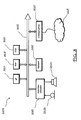
- Reference numerals 105a , 105b and 105c denote three persons engaged in an virtual audio conference, exploiting respective communication terminals 110a , 110b and 110c , like for example video-telephones, Personal Digital Assistants (PDAs), mobile phones, personal computers, interconnected through a telecommunication network 115 that may include a wireline and/or wireless telephone network, and a packet data network like the Internet.
- a telecommunication network 115 may include a wireline and/or wireless telephone network, and a packet data network like the Internet.
- the three persons (peers) 105a , 105b and 105c involved in the virtual audio conference can each talk to, and be seen by the other two peers, and each of the three peers can listen to and see the other two peers. This is made possible by a conference mixer, the main functionality of which is to provide "virtual conferencing" user experience.
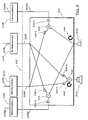
- FIG. 2 the main components of an audio conference mixer according to an embodiment of the present invention are schematically shown.
- the conference mixer is hosted by one of the terminals (endpoints) of the three peers engaged in the virtual audio conference, in the shown example at the endpoint 110c of the peer 105c (the "peer C"). It is sufficient that the endpoint of at least one of the peers involved in the virtual conference hosts the conference mixer (in general, the conference mixer may be hosted by the endpoint of the peer that initiates the virtual conference), however nothing prevents that a conference mixer is also hosted by one or more of the endpoints of the other peers.
- the conference mixer 205 comprises a first mixer 220 configured to receive audio data streams 225a and 225c , respectively received from the endpoint 110a of the peer 105a (the "peer A") and generated by the endpoint 110c of the peer C, and to generate a mixed audio data stream 225ac to be sent to the endpoint 110b of the peer 105b (the "peer B").
- the audio data streams 225a and 225c are generated by capturing devices like microphones 215a and 215c of the endpoints 110a and 110c ; at the endpoint 110b, the mixed audio data stream 225ac is rendered by a rendering device like a loudspeaker 210b .
- the conference mixer further comprises a second mixer 230 , configured to receive the audio data stream 225c , generated by the endpoint 110c of the peer C, and an audio data stream 225b received from the endpoint 110b of the peer B, and to generate a mixed audio data stream 225bc to be sent to the endpoint 110a of the peer A.
- the audio data stream 225b is generated by a microphone 215b of the endpoints 110b ; at the endpoint 110a , the mixed audio data stream 225bc is rendered by a loudspeaker 210a.
- the conference mixer further comprises a third mixer 235 , configured to receive the audio data stream 225a , received from the endpoint 110a of the peer A, and the audio data stream 225b , received from the endpoint 110b of the peer B, and to generate a mixed audio data stream 225ab , rendered by a loudspeaker 210c of the endpoint 110c.
- a third mixer 235 configured to receive the audio data stream 225a , received from the endpoint 110a of the peer A, and the audio data stream 225b , received from the endpoint 110b of the peer B, and to generate a mixed audio data stream 225ab , rendered by a loudspeaker 210c of the endpoint 110c.
- the audio data streams are in digital format
- the mixers are digital mixers.
- the number of data stream mixers of the conference mixer 205 as well as the number of data streams that each of the mixers is configured to receive and mix, depend on the number of peers engaged in the virtual conference.
- the conference mixer 205 differs from the operation performed by a MCU provided in the core network.
- the conference mixer 205 integrates the operations of grabbing, rendering and mixing in a single device (the device 110c), while a MCU in the core network performs all the operation relevant to a rendering device in order to have access to the audio samples to be mixed, mixes them and transmits (possibly compressing) to the appropriate peer.
- FIG. 3 there is schematically depicted the hardware structure of the endpoint 110c that hosts the conference mixer 205. Essentially, it is the general structure of a data processing apparatus, with several units that are connected in parallel to an internal data communication bus 305 .
- a data processor (microprocessor or microcontroller) 310 controls the operation of the terminal 110c ;
- a RAM (Random Access Memory) 315 is directly used as a working memory by the data processor 310
- a ROM (Read Only Memory) 320 stores the microcode (firmware) to be executed by the data processor 310 .
- a communication subsystem 325 includes hardware devices for handling at least the physical level of the communications over the telephone/telecommunications network 115 ; a keyboard 330 is provided for dialing the telephone numbers; an audio/video subsystem 335 manages the loudspeaker/display device 210c and the microphone/videocamera 215c .
- Figure 4 shows the partial content of the working memory 315 of the terminal 110c during a virtual conference between the peers A, B and C; thus, the functional blocks depicted in Figure 4 are to be intended as software/firmware modules, or instances of software/firmware modules. This is however not to be construed as a limitation of the present invention, which might be implemented totally in hardware, or as a combination of hardware and software/firmware.
- Blocks 405a and 405b represent instances of a grabbing multimedia software module, adapted to perform the tasks of grabbing the mixed audio data streams 225bc' and, respectively, 225ac', code them to obtain coded ( i.e . compressed) data streams 225bc and, respectively, 225ac, and of transmitting them over the telephone/telecommunications network 115 to the endpoints 110a and, respectively, 110b of the peers A and B.
- the mixing operation of the audio data streams that generates the mixed audio data streams 225bc and 225ac is performed in the uncompressed domain (on Pulse Code Modulated values); this avoids the problem of compatibility between different compression algorithms (for example G.723, AMR, G.722) that may have been negotiated between the different peers (in other words, peers A and C might have negotiated a compression algorithm different from that negotiated between the peers B and C).
- the grabbing multimedia software module instances 405a and 405b are also responsible of the encoding the mixed audio data streams 225bc and 225ac in a respective, predetermined coding standard, that may be different for the different peers A and B of the virtual conference.
- Blocks 410a and 410b represent instances of a rendering multimedia software module adapted to perform the tasks (independent from the grabbing tasks performed by blocks 405a and 405b ) of receiving the audio data streams 225a and 225b , respectively, transmitted by the endpoints 110a and, respectively, 110b over the telephone/telecommunications network 115, decode the received audio data streams 225a and 225b to obtain decoded data streams 225a ' and 225b ', and render them through the loudspeaker 210c of the endpoint 110c.
- the grabbing and rendering multimedia software module instances 405a , 405b , 410a and 410b are user-space applications, running at the application layer level in the endpoint 110c .
- the working memory of a data processor can ideally be divided into two basic memory spaces: a "user space” and a "kernel space".
- the user space is the memory region where the user software/firmware applications or executables reside and run.
- kernel space is the memory region where the kernel software/firmware modules or executables reside; kernel software/firmware modules are software/firmware modules forming the core of an operating system which is started at the bootstrap of the data processor, and whose function is to provide an environment in which other programs can run, provide hardware services to them (like supplying memory and access to space on storage devices), schedule their execution and allow multiple processes to coexist.
- the grabbing and rendering multimedia software module instances 405a , 405b , 410a and 410b exploit dedicated library modules, typically user-space library modules.
- Kernel-space device drivers are used when the operating system prevents user-space applications to access directly the hardware resources; normally this is related to the presence of hierarchical protection domains (or protection rings) in the operating system, acting as a protection method from application-generated faults.
- Device drivers can run in user space (and thus act as a user-space library modules) when the operating system does not implement protection rings concepts.
- the conference mixer 205 is implemented as a user-space process or thread, preferably of high priority, running in the endpoint 110c ; in this case, the conference mixer 205 can replace the library modules used by the instances 405a , 405b , 410a and 410b of the user-space grabbing and rendering multimedia modules (application layer) to access the capturing and rendering audio resources 210c and 215c.
- the conference mixer 205 might be implemented as a kernel-space device driver.
- the conference mixer 205 replaces the kernel device driver normally responsible of handling the audio grabbing and rendering operations.
- line 415 indicates an API exposed by the conference mixer 205 , through which it can be accessed by the grabbing and rendering multimedia software module instances 405a, 405b , 410a and 410b.
- the API 415 replicates the same functionalities provided by the library modules used to access the I/O resources 210c and 215c .
- the behavior of the multimedia rendering and grabbing module instances 405a , 405b , 410a and 410b does not need to be changed in order to allow them interact with the conference mixer 205 (whose presence is thus transparent to the multimedia rendering and grabbing module instances 405a , 405b , 410a and 410b ).
- the conference mixer 205 comprises (in the example herein considered of virtual conference involving three peers) three audio data stream chunk mixers 420 , 425 and 430 , adapted to mix portions (or chunks) of the audio data streams.
- Two data buffers 420-1 and 420-2 , 425-1 and 425-2 , and 430-1 and 430-2 are operatively associated with each of the mixers 420 , 425 and 430 .
- Data buffers 420-1 and 425-1 are the data contribution buffers provided in respect of the audio data streams coming from the peers A and, respectively, B, for grabbing purposes.
- Data buffers 420-2 and 425-2 are the data recipient buffers for the mixed audio data streams to be sent to the peers B and, respectively, A.
- Data buffers 430-1 and 430-2 are the mixer contribution buffers for the audio data streams received from the peers A and B, respectively, for rendering purposes.
- the mixers 420 , 425 and 430 are digital mixers.
- the number of mixers and associated buffers increases; in particular, for each additional peer participating to the virtual conference, a mixer like the mixer 420 , with an associated pair of buffers like the buffers 420-1 and 420-2 needs to be added; also, a buffer like the buffer 430-1 or 430-2 has to be added for each additional peer.
- Reference numeral 435 denotes an audio rendering procedure, for sending audio data streams chunks ready to be rendered to the loudspeaker 210c , for rendering them.
- Reference numeral 440 denotes an audio capturing procedure, for receiving audio data captured by the microphone 215c .
- the mixing operations performed by the mixers 420 , 425 and 430 may be implemented as high priority threads/processes.
- high priority processes it is intended threads/processes running at a priority higher than the normal tasks.
- high priority is intended to mean the highest possible priority (closest to real-time priority), that does not jeopardize the system stability.
- the mixing operations performed by the mixers 420 , 425 and 430 may be implemented as interrupt service routines, that are started as soon as an interrupt is received from the rendering and capturing devices.
- the mixing operations are performed at the Input/Output (I/O) rate ( i.e ., at the rate at which data are captured by the capturing devices 215c , and at the rate data to be rendered are consumed by the rendering devices 210c ).
- I/O Input/Output
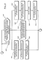
- the operation of the conference mixer 205 is explained in detail herein below, referring to the flowchart of Figure 5 .
- the rendering devices 210c and the capturing devices 215c operate on a same time base, i.e. with a same clock, so that they (their I/O interfaces) generate simultaneous interrupts (i.e.
- the elder data chunks present in the mixer contribution buffers 430-1 and 430-2 are taken (block 510 ), they are mixed together on the fly (block 515 ) and the mixed data are fed to the loudspeaker 210c for rendering (block 520 ).
- the arrival of the render time of the new audio data chunk is an event 507 that may be signaled by a notification, like an interrupt from the (input interface of the) loudspeaker 210c , if the conference mixer 205 is implemented as a kernel-space device driver, or said notification may be an asynchronous notification from the loudspeaker driver, in case the conference mixer 205 is implemented as a user-space process.
- the arrival of the render time of a new data chunk coincides with the arrival of the grabbing time of a new audio data chunk; however, in general, when the grabbing time of a new audio data chunk arrives (also in this case, this event can be an interrupt, if the conference mixer is implemented as a kernel-space device driver, or it can be an asynchronous notification from the microphone driver), the freshly captured audio data chunk is taken (block 525 ), the elder data chunks present in the data contribution buffers 420-1 and, respectively, 425-1 are taken (block 530 ), and they are mixed, by the mixers 420 and 425 , with the freshly captured data chunk (block 535), to produce a new chunk of mixed audio to be sent to the peers, and the mixed data are put in the data recipient buffers 420-1 and 425-2 , respectively (block 540 ).
- the grabbing multimedia software module instances 405a and 405b then fetch the elder mixed audio data chunks from the respective data recipient buffer 425-2
- the arrival of the render time of the new audio data chunk is also used to trigger the load of the mixer contribution buffers 430-1 and 430-2 with a new audio frame (i.e ., a part, a fragment of the audio data stream) made available by the rendering multimedia software module instances 410a and 410b (block 545 ), which accesses the conference mixer 205 through the rendering API it exposes; in this description, the term trigger means signaling to the multimedia rendering software module instances 410a and 410b that free space is available in the associated buffer 430-.1 and 430-2 .
- the multimedia rendering software module instances can then (when data are available) write a new audio frame into the buffers 430-1 and 430-2 ; the same audio frame is also copied into the respective data contribution buffer 420-1 or 425-1 .
- the size of the audio data chunks to be stored in the buffers significant parameters for determining it are the number of bits per audio sample (for example, 16 bits), the sampling rate (for example, 8kHz for narrow band compression algorithms like G.723, or 16kHz for wide band compression algorithms like G.722.2), the duration of the audio frame, i.e . the minimum amount of data handled by the chosen compression algorithm (for example, 10ms for G.729, 30ms for G.723, 20ms for G722).
- the size of the audio frames coming from the two peers may be different. This introduces additional cases of underflow during the mixing operation: if the amount of data available from all the different contributors of the mixing operation is not enough to produce a complete data chunk in output, a glitch is introduced.
- the conference mixer 205 may compute a single data chunk size, that is used for all the buffers, using the lowest common multiple of all the audio frame sizes used by the different conference peers. For example, assuming that peer A transmits (and receives) audio frames of 30 ms, and peer B transmits (and receives) audio frames of 20 ms, the size of the audio data chunk used by the conference mixer (i.e ., the "quantum" of audio data processed by the conference mixer 205 ) may be 60 ms; this means that every 60 ms, an interrupt arrives from the loudspeaker 210c , and a new data chunk of 60 ms is generated on-the-fly by the mixer 430 and sent to the loudspeaker 210c (similarly, under the assumption that a single time base exists, every 60 ms a new data chunk of audio captured by the microphone 215c is ready).
- the number of data chunks that the generic buffer of the conference mixer 205 is designed to store is tuned taking into consideration the interrupt latency time or the task switch latency time provided by the equipment/operating system hosting the multimedia modules. Under the assumption that the latency time is lower than the duration (i.e . the size) of a data chunk, the number of data chunks can be kept to the minimum (each buffer has two registers, each of the size of one data chunk, that are used in a "ping-pong" access mode, alternatively for reading and writing).
- each buffer can store two data chunks
- each buffer can feed the old data chunk to (from) the rendering (capturing) device.
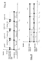
- the minimum end-to-end delay introduced by the conference mixer 205 is equal to the duration of one audio data chunk between the peers A and C and between the peers B and C (as described in Figure 6 ).
- the additional end-to-end delay introduced by the mixer is equal to the waiting time that a data chunk has to wait in the buffer 430-1 or 430-2 before rendering. In order to avoid underflow in one of the aforementioned buffer, a minimum waiting time of one data chunk time is needed. No additional end-to-end delay is instead introduced in the grabbing path from peer C to peer A or B.
- the buffers that introduce end-to-end delay are the buffers 420-1 , 425-1 , 430-1 and 430-2.
- Interrupt INT(n-1) starts the rendering of the (n-1)-th audio data chunk
- interrupt INT(n) starts the rendering of the n-th audio data chunk, and so on.
- the generic one of the rendering multimedia software module instances 410a or 410b starts writing (event Ws(n) ) the n -th audio frame to the respective mixer contribution buffer 430-1 and 430-2 at instant T n-1 , when the audio rendering procedure 435 receives the interrupt INT(n-1) for starting to play the (n-1)-th data chunk; the writing of the n-th audio frame to the mixer contribution buffer ends (event We(n) ) before the arrival of the next interrupt INT(n) , thus when this next interrupt arrives the new audio data chunk is ready to be played; when, at instant T n , the audio rendering procedure 435 receives the next interrupt INT(n) for starting to play the (n)-th data chunk, the rendering multimedia software module instance 410a or 410b start writing (event Ws(n+1) ) the (n+1)-th audio frame to the respective mixer contribution buffers 430-1 and 430-2 ; the
- the rendering multimedia software module instance 410b also starts making available the n-th frame of the audio stream coming from the peer B.
- the rendering multimedia software module instance 410a completes the n-th audio frame, and starts making available the (n+1) audio frame; the rendering multimedia software module instance 410b instead completes the n-th audio frame later, at instant T n+a .
- the rendering multimedia software module instance 410a completes the (n+1)-th audio frame at instant T n+1
- the rendering multimedia software module instance 410b completes the (n+1)-th audio frame later, at instant T n+1+a
- the rendering multimedia software module instance 410a completes the (n+2)-th audio frame at instant T n+2
- the rendering multimedia software module instance 410b completes the (n+2)-th audio frame later, at instant T n+3
- the two rendering multimedia software module instance 410a and 410b are again synchronized.
- the mixer contribution buffers 430-1 and 430-2 may be designed so as to contain data chunks of size equal to four audio frames from peer A, and three audio frames from peer B.
- the size of the data chunks used by the conference mixer 205 may be equal to maximum common divisor, instead of the lowest common multiple, of the audio frames adopted by the different peers.
- the conference mixer 205 may be designed to work with data chunks of 10 ms; this means that every 10 ms, an interrupt arrives from the loudspeaker 210c, and a new data chunk of 10 ms is generated (by mixing data chunks of 10 ms of the audio frames stored in the mixer contribution buffers 430-1 and 430-2 ) on-the-fly by the mixer 430 and sent to the loudspeaker 210c ;every two interrupts, the rendering multimedia software module instance 410b is notified that in the buffer 430-2 there is space for a new audio frame, while this happens every three interrupts for the rendering multimedia software module
- the usage of the conference mixer 205 is selectable by the user on a per -connection basis: during a communication involving just two peers, like for example peers A and C, or peers B and C, no mixing is needed, while the mixing becomes necessary during a multi-peer (three or more) session.
- the conference mixer 205 may be adapted to "auto enabling" when a third peer of a virtual conference starts producing an requesting audio data chunks.
- the conference mixer could be not used, thus avoiding introducing additional end-to-end delay, and when a third peer enters the communication session, the mixer could be inserted.
- this live, on-the-fly insertion of the conference mixer is a time consuming operation that might cause long artifacts.
- the conference mixer 205 in order to both avoid adding end-to-end delay when the mixing operation is not needed, and at the same time avoid the artifacts caused by the delay of insertion of the mixer when the third peer enter the conference, the conference mixer 205 is already used since the beginning of the communication between the first two peers, and the buffering is reduced to the minimum required by the number of peers actively engaged in the conference.
- actively engaged it is meant having “open” rendering/grabbing devices.
- the engagement of the mixer does not rely on the data flow (to or from its data interfaces) but on the explicit intention of a multimedia software module (grabbing or rendering) to start a new session; data flow in fact can be discontinuous as it is related to data availability fro the remote peer.
- peers A and C when only two peers, e.g . peers A and C are active, no mixing operations are needed and the conference mixer 205 prevents buffering of audio data chunks in the data contribution buffer 420-1 and in the mixer contribution buffer 430-1 .
- Data chunks are directly written by the rendering multimedia software module instance 410a to the output device 210c , without any buffering. In this way, no extra delay is introduced.
- the thread 435 that, when the mixer is enabled, working synchronously with the interrupts received from the output rendering device 210c, takes the data chunks from the mixer contribution buffers 430-1 and 430-2 , when the mixer is disabled does not perform any mixing, but it is only responsible for signaling to the rendering multimedia software module instance 410a that the device is ready for rendering.
- a similar behavior is performed by the grabbing thread. When a new peer, like peer B, becomes active, the mixing operation, and the relevant buffering operations are re-enabled.
- the rendering and grabbing multimedia software modules do not need to change behavior when the conference-mixer is enabled. This reduces the complexity of the software itself, especially in a crucial part as the low latency handling of audio.
- the present invention can also be applied to audio/video virtual conferences, by adding the buffers and mixers for the video component in an analogous manner as that described in the foregoing.
Landscapes
- Engineering & Computer Science (AREA)
- Multimedia (AREA)
- Signal Processing (AREA)
- General Engineering & Computer Science (AREA)
- Telephonic Communication Services (AREA)
- Two-Way Televisions, Distribution Of Moving Picture Or The Like (AREA)
Claims (16)
- Telekommunikationsterminal (110c), das als Host für einen Konferenzmischer (205) dient, der so ausgelegt ist, dass er eine Konferenz, die mindestens Audio umfasst, zwischen einem ersten Konferenzpartner (105c) und mindestens zwei weiteren Konferenzpartner (105a, 105b) ermöglicht, wobei der Konferenzmischer umfasst:- für jeden der mindestens zwei weiteren Konferenzpartner einen entsprechenden ersten Datenpuffer (430-1, 430-2), der zum Puffern von Abschnitten mindestens eines Audiodatenstroms konfiguriert ist, der vom jeweiligen Konferenzpartner empfangen wird,- einen ersten Audiodatenstromabschnittmischer (430), der von den ersten Datenpuffern beliefert wird und konfiguriert ist zum:dadurch gekennzeichnet, dass der erste Audiodatenstromabschnittmischer so konfiguriert ist, dass er die Operationen a), b) und c) bei Empfang einer Benachrichtigung (507) von der Renderingvorrichtung durchführt, die anzeigt, dass die Renderingvorrichtung bereit ist, einen neuen gemischten Audiodatenabschnitt zu rendern.a) Erhalten von Audiodatenstromabschnitten, die in den ersten Datenpuffern gepuffert sind;b) Mischen der von den ersten Datenpuffern erhaltenen Audiodatenstromabschnitte, um einen ersten gemischten Audiodatenabschnitt zu erzeugen; undc) Liefern des ersten gemischten Audiodatenabschnitts an eine Renderingvorrichtung (210c) des Telekommunikationsterminals,
- Telekommunikationsterminal nach Anspruch 1, wobei die Renderingvorrichtung einen Lautsprecher umfasst.
- Telekommunikationsterminal nach Anspruch 1 oder 2, wobei jeder der ersten Datenpuffer mindestens zwei Speicherbereiche umfasst, die jeweils zum Speichern mindestens eines Fragments des vom jeweiligen Partner empfangenen Audiodatenstroms ausgelegt sind.
- Telekommunikationsterminal nach Anspruch 3, wobei jeder der ersten Datenpuffer so konfiguriert ist, dass er von einer jeweiligen Renderingfunktion (410a, 410b) beliefert wird, wobei die Renderingfunktion so ausgelegt ist, dass sie den Audiodatenstrom vom jeweiligen Konferenzpartner empfängt und dem jeweiligen ersten Datenpuffer Fragmente einer vorbestimmten Größe der Audiodatenströme bereitstellt.
- Telekommunikationsterminal nach Anspruch 4, wobei jeder der Speicherbereiche eine Größe gleich einem höchsten gemeinsamen Teiler der Größen der Fragmente der Audiodatenströme aufweist, die von der Renderingfunktion der mindestens zwei weiteren Partner erzeugt werden.
- Telekommunikationsterminal nach Anspruch 4, wobei jeder der Speicherbereiche eine Größe gleich einem niedrigsten gemeinsamen Vielfachen der Größen der Fragmente der Audiodatenströme aufweist, die von der Renderringfunktion der mindestens zwei weiteren Partner erzeugt werden.
- Telekommunikationsterminal nach einem der vorhergehenden Ansprüche, ferner umfassend:- für jeden der mindestens zwei weiteren Konferenzpartner einen entsprechenden zweiten Datenpuffer (420-1, 425-1), der zum Puffern der Abschnitte mindestens eines Audiodatenstroms konfiguriert ist, der vom anderen Konferenzpartner empfangen wird,- einen zweiten Audiodatenstromabschnittmischer (430), der von den zweiten Datenpuffern beliefert wird und konfiguriert ist zum:wobei der zweite Audiodatenstromabschnittmischer so konfiguriert ist, dass er die Operationen d), e) und f) bei Empfang einer Benachrichtigung (507) von der Aufnahmevorrichtung durchführt, die anzeigt, dass die Aufnahmevorrichtung einen neuen Audiodatenstromabschnitt aufgenommen hat.d) Erhalten von Audiodatenstromabschnitten, die in den zweiten Datenpuffern gepuffert sind;e) Erhalten von Audiodatenstromabschnitten von einer Aufnahmevorrichtung (215c) des Telekommunikationsterminals; undf) Mischen der von den zweiten Datenpuffern erhaltenen Audiodatenstromabschnitte und der von der Aufnahmevorrichtung erhaltenen Audiodatenstromabschnitte, um einen jeweiligen zweiten gemischten Audiodatenabschnitt zu erzeugen, der an einen jeweiligen der mindestens zwei weiteren Konferenzpartner gesendet werden soll,
- Telekommunikationsterminal nach Anspruch 7, die ferner umfasst:- für jeden der mindestens zwei weiteren Konferenzpartner einen entsprechenden dritten Datenpuffer (420-2, 425-2), der zum Puffern der zweiten gemischten Audiodatenabschnitte konfiguriert ist, die vom jeweiligen zweiten Audiodatenstromabschnittmischer erzeugt werden.
- Telekommunikationsterminal nach Anspruch 8, wobei jeder der dritten Datenpuffer so konfiguriert ist, dass er eine jeweilige Aufnahmefunktion (415a, 415b) beliefert, wobei die Aufnahmefunktion zum Senden des Audiodatenstroms an den jeweiligen Konferenzpartner ausgelegt ist.
- Telekommunikationsterminal nach Anspruch 4, das ferner eine erste Anwendungsprogrammschnittstelle umfasst, um Zugriff darauf durch die Renderringfunktionen zu ermöglichen.
- Telekommunikationsterminal nach Anspruch 9, das ferner eine zweite Anwendungsprogrammschnittstelle umfasst, um Zugriff darauf durch die Aufnahmefunktion zu ermöglichen.
- Telekommunikationsterminal nach Anspruch 10 oder 11, wobei der Konferenzmischer so konfiguriert ist, dass er als ein Benutzerraumprozess implementiert ist, der in einem Benutzerraum des Telekommunikationsterminals ausgeführt wird.
- Telekommunikationsterminal nach Anspruch 10 oder 11, wobei der Konferenzmischer so konfiguriert ist, dass er als ein Kernraumprozess implementiert ist, der in einem Kernraum des Telekommunikationsterminals ausgeführt wird.
- Telekommunikationsterminal nach einem der vorhergehenden Ansprüche, wobei der Konferenzmischer ferner konfiguriert ist zum:- Erkennen des Vorhandenseins von mindestens zwei weiteren Konferenzpartnern;- automatischen Aktivieren des ersten Audiodatenstromabschnittmischers bei Erkennen der mindestens zwei weiteren Partner;- automatischen Deaktivieren des ersten Audiodatenstromabschnittmischers, falls das Vorhandensein von nur einem weiteren Partner erkannt wird.
- Telekommunikationsterminal nach Anspruch 14, wobei der Konferenzmischer ferner so konfiguriert ist, dass er die zweiten Audiodatenstromabschnittmischer bei Erkennen des Vorhandenseins der mindestens zwei weiteren Partner aktiviert und die zweiten Audiodatenstromabschnittmischer automatisch deaktiviert, falls das Vorhandensein von nur einem weiteren Partner erkannt wird.
- Verfahren zur Durchführung einer Konferenz, die mindestens Audio umfasst, zwischen einem ersten Konferenzpartner (105c) und mindestens zwei weiteren Konferenzpartnern (105a, 105b), wobei das Verfahren umfasst:- Durchführen an einem Telekommunikationsterminal (110c) des ersten Konferenzpartners eines ersten Pufferns von Abschnitten mindestens eines Audiodatenstroms, der von jedem der mindestens zwei weiteren Konferenzpartner empfangen wird; und gekennzeichnet durch:- bei Empfang einer Benachrichtigung (507) von einer Renderingvorrichtung (210c) des Telekommunikationsterminals, die anzeigt, dass die Renderingvorrichtung bereit ist, einen neuen gemischten Audiodatenabschnitt wiederzugeben:- Mischen der beim ersten Puffern gepufferten Audiodatenstromabschnitte, um den gemischten Audiodatenabschnitt zu erzeugen; und- Liefern des gemischten Audiodatenabschnitts an die Renderingvorrichtung.
Applications Claiming Priority (1)
| Application Number | Priority Date | Filing Date | Title |
|---|---|---|---|
| PCT/EP2006/012598 WO2008080426A1 (en) | 2006-12-29 | 2006-12-29 | Conference where mixing is time controlled by a rendering device |
Publications (2)
| Publication Number | Publication Date |
|---|---|
| EP2103098A1 EP2103098A1 (de) | 2009-09-23 |
| EP2103098B1 true EP2103098B1 (de) | 2012-11-21 |
Family
ID=38328474
Family Applications (1)
| Application Number | Title | Priority Date | Filing Date |
|---|---|---|---|
| EP06841205A Active EP2103098B1 (de) | 2006-12-29 | 2006-12-29 | Konferenz, bei der die mischung durch eine wiedergabeeinrichtung zeitgesteuert wird |
Country Status (4)
| Country | Link |
|---|---|
| US (1) | US7965660B2 (de) |
| EP (1) | EP2103098B1 (de) |
| ES (1) | ES2401975T3 (de) |
| WO (1) | WO2008080426A1 (de) |
Families Citing this family (10)
| Publication number | Priority date | Publication date | Assignee | Title |
|---|---|---|---|---|
| US20110106282A1 (en) * | 2009-07-23 | 2011-05-05 | Corevalus Systems, Llc | Audio Processing Utilizing a Dedicated CPU Core and a Real Time OS |
| US9449614B2 (en) * | 2009-08-14 | 2016-09-20 | Skype | Controlling multi-party communications |
| EP2611127A1 (de) * | 2011-12-29 | 2013-07-03 | Gface GmbH | Kombinierte Datenströme |
| JP6260926B2 (ja) * | 2013-06-12 | 2018-01-17 | 株式会社リコー | 通信装置、通信システム、通信装置の動作方法及びプログラム |
| US10708328B2 (en) * | 2014-03-17 | 2020-07-07 | Intel Corporation | Hardware assisted media playback and capture synchronization |
| US9979769B2 (en) * | 2014-04-18 | 2018-05-22 | Nuance Communications, Inc. | System and method for audio conferencing |
| US10237412B2 (en) * | 2014-04-18 | 2019-03-19 | Nuance Communications, Inc. | System and method for audio conferencing |
| US10318361B2 (en) | 2014-07-02 | 2019-06-11 | Atheer, Inc. | Methods and systems for multiple access to a single hardware data stream |
| US9628206B2 (en) * | 2015-01-03 | 2017-04-18 | ClearOne Inc. | Endpoint parameter management architecture for audio mixers |
| NO348822B1 (en) * | 2020-12-18 | 2025-06-16 | Pexip AS | Method and system for real time audio in multi-point video conferencing |
Family Cites Families (15)
| Publication number | Priority date | Publication date | Assignee | Title |
|---|---|---|---|---|
| JPH0537655A (ja) | 1991-07-26 | 1993-02-12 | Fujitsu Ltd | 音声多地点通信方式 |
| US5390177A (en) | 1993-03-24 | 1995-02-14 | At&T Corp. | Conferencing arrangement for compressed information signals |
| US5666407A (en) | 1995-12-05 | 1997-09-09 | Ncr Corporation | Software-based bridging system for full duplex audio telephone conferencing |
| CA2224541C (en) | 1997-01-07 | 2008-06-17 | Northern Telecom Limited | Method of providing conferencing in telephony |
| AU1115001A (en) * | 1999-10-22 | 2001-05-08 | Activesky, Inc. | An object oriented video system |
| US6594773B1 (en) * | 1999-11-12 | 2003-07-15 | Microsoft Corporation | Adaptive control of streaming data in a graph |
| US7062437B2 (en) * | 2001-02-13 | 2006-06-13 | International Business Machines Corporation | Audio renderings for expressing non-audio nuances |
| US20050005308A1 (en) * | 2002-01-29 | 2005-01-06 | Gotuit Video, Inc. | Methods and apparatus for recording and replaying sports broadcasts |
| US7130280B2 (en) | 2002-01-30 | 2006-10-31 | Lucent Technologies Inc. | Enhanced call service packet data terminal |
| AU2003257054A1 (en) * | 2002-08-16 | 2004-03-03 | Nuasis Corporation | Escalated handling of non-realtime communications |
| US8140980B2 (en) * | 2003-08-05 | 2012-03-20 | Verizon Business Global Llc | Method and system for providing conferencing services |
| US20060031607A1 (en) * | 2004-08-05 | 2006-02-09 | Microsoft Corporation | Systems and methods for managing input ring buffer |
| US7474983B2 (en) * | 2005-01-05 | 2009-01-06 | Massachusetts Institute Of Technology | Method for object identification and sensing in a bounded interaction space |
| US20060173972A1 (en) * | 2005-01-31 | 2006-08-03 | Searete Llc, A Limited Liability Corporation Of The State Of Delaware | Audio sharing |
| US20080119165A1 (en) * | 2005-10-03 | 2008-05-22 | Ajay Mittal | Call routing via recipient authentication |
-
2006
- 2006-12-29 EP EP06841205A patent/EP2103098B1/de active Active
- 2006-12-29 US US12/448,644 patent/US7965660B2/en active Active
- 2006-12-29 WO PCT/EP2006/012598 patent/WO2008080426A1/en not_active Ceased
- 2006-12-29 ES ES06841205T patent/ES2401975T3/es active Active
Also Published As
| Publication number | Publication date |
|---|---|
| ES2401975T3 (es) | 2013-04-25 |
| US7965660B2 (en) | 2011-06-21 |
| US20100039962A1 (en) | 2010-02-18 |
| EP2103098A1 (de) | 2009-09-23 |
| WO2008080426A1 (en) | 2008-07-10 |
Similar Documents
| Publication | Publication Date | Title |
|---|---|---|
| US5463616A (en) | Method and apparatus for establishing a full-duplex, concurrent, voice/non-voice connection between two sites | |
| EP2103098B1 (de) | Konferenz, bei der die mischung durch eine wiedergabeeinrichtung zeitgesteuert wird | |
| US9955205B2 (en) | Method and system for improving interactive media response systems using visual cues | |
| US6084911A (en) | Transmission of coded and compressed voice and image data in fixed bit length data packets | |
| US20110002376A1 (en) | Latency Minimization Via Pipelining of Processing Blocks | |
| US10432543B2 (en) | Dual jitter buffers | |
| EP0817045A2 (de) | Mischung und Trennung mehrerer unabhängiger Audiodatenströme in einem Betriebssystemkern | |
| CN107113423B (zh) | 重放用于隐藏视频解码错误的旧分组和基于无线链路状况的视频解码等待时间调整 | |
| WO1994029979A1 (en) | Method and apparatus for multiple media digital communication system | |
| US20070047590A1 (en) | Method for signaling a device to perform no synchronization or include a synchronization delay on multimedia stream | |
| US8687016B2 (en) | Method and system for enhancing the quality of video prompts in an interactive media response system | |
| US20060123063A1 (en) | Audio and video data processing in portable multimedia devices | |
| US20060133513A1 (en) | Method for processing multimedia streams | |
| CA2585295C (en) | System and method for synchronous processing of media data on an asynchronous processor | |
| GB2511822A (en) | A telecommunication network | |
| EP2429162A1 (de) | Sitzservice-verarbeitungsverfahren und ip-sitz-endgerät | |
| US7403605B1 (en) | System and method for local replacement of music-on-hold | |
| US20120075408A1 (en) | Technique for providing in-built audio/video bridge on endpoints capable of video communication over ip | |
| US20180227671A1 (en) | Sound sharing apparatus and method | |
| CN107277425A (zh) | 一种服务器、会场终端以及云会议处理方法 | |
| JP2007036638A (ja) | 携帯端末装置及びそれに用いるディジタル放送受信再生方法 | |
| Chodrow et al. | Design and implementation of a multicast audio conferencing tool for a collaborative computing framework | |
| Drude et al. | System architecture for a multi-media enabled mobile terminal | |
| EP1851962B1 (de) | Verfahren und anordnungen zum ausrichten von diensten | |
| JP6476768B2 (ja) | 音声処理装置、プログラム及び方法 |
Legal Events
| Date | Code | Title | Description |
|---|---|---|---|
| PUAI | Public reference made under article 153(3) epc to a published international application that has entered the european phase |
Free format text: ORIGINAL CODE: 0009012 |
|
| 17P | Request for examination filed |
Effective date: 20090722 |
|
| AK | Designated contracting states |
Kind code of ref document: A1 Designated state(s): AT BE BG CH CY CZ DE DK EE ES FI FR GB GR HU IE IS IT LI LT LU LV MC NL PL PT RO SE SI SK TR |
|
| 17Q | First examination report despatched |
Effective date: 20100215 |
|
| DAX | Request for extension of the european patent (deleted) | ||
| GRAP | Despatch of communication of intention to grant a patent |
Free format text: ORIGINAL CODE: EPIDOSNIGR1 |
|
| GRAS | Grant fee paid |
Free format text: ORIGINAL CODE: EPIDOSNIGR3 |
|
| GRAA | (expected) grant |
Free format text: ORIGINAL CODE: 0009210 |
|
| AK | Designated contracting states |
Kind code of ref document: B1 Designated state(s): AT BE BG CH CY CZ DE DK EE ES FI FR GB GR HU IE IS IT LI LT LU LV MC NL PL PT RO SE SI SK TR |
|
| REG | Reference to a national code |
Ref country code: GB Ref legal event code: FG4D |
|
| REG | Reference to a national code |
Ref country code: CH Ref legal event code: EP |
|
| REG | Reference to a national code |
Ref country code: AT Ref legal event code: REF Ref document number: 585573 Country of ref document: AT Kind code of ref document: T Effective date: 20121215 |
|
| REG | Reference to a national code |
Ref country code: IE Ref legal event code: FG4D |
|
| REG | Reference to a national code |
Ref country code: DE Ref legal event code: R096 Ref document number: 602006033274 Country of ref document: DE Effective date: 20130110 |
|
| REG | Reference to a national code |
Ref country code: NL Ref legal event code: T3 |
|
| REG | Reference to a national code |
Ref country code: AT Ref legal event code: MK05 Ref document number: 585573 Country of ref document: AT Kind code of ref document: T Effective date: 20121121 |
|
| REG | Reference to a national code |
Ref country code: ES Ref legal event code: FG2A Ref document number: 2401975 Country of ref document: ES Kind code of ref document: T3 Effective date: 20130425 Ref country code: LT Ref legal event code: MG4D |
|
| PG25 | Lapsed in a contracting state [announced via postgrant information from national office to epo] |
Ref country code: FI Free format text: LAPSE BECAUSE OF FAILURE TO SUBMIT A TRANSLATION OF THE DESCRIPTION OR TO PAY THE FEE WITHIN THE PRESCRIBED TIME-LIMIT Effective date: 20121121 Ref country code: SE Free format text: LAPSE BECAUSE OF FAILURE TO SUBMIT A TRANSLATION OF THE DESCRIPTION OR TO PAY THE FEE WITHIN THE PRESCRIBED TIME-LIMIT Effective date: 20121121 Ref country code: LT Free format text: LAPSE BECAUSE OF FAILURE TO SUBMIT A TRANSLATION OF THE DESCRIPTION OR TO PAY THE FEE WITHIN THE PRESCRIBED TIME-LIMIT Effective date: 20121121 |
|
| PG25 | Lapsed in a contracting state [announced via postgrant information from national office to epo] |
Ref country code: PL Free format text: LAPSE BECAUSE OF FAILURE TO SUBMIT A TRANSLATION OF THE DESCRIPTION OR TO PAY THE FEE WITHIN THE PRESCRIBED TIME-LIMIT Effective date: 20121121 Ref country code: GR Free format text: LAPSE BECAUSE OF FAILURE TO SUBMIT A TRANSLATION OF THE DESCRIPTION OR TO PAY THE FEE WITHIN THE PRESCRIBED TIME-LIMIT Effective date: 20130222 Ref country code: LV Free format text: LAPSE BECAUSE OF FAILURE TO SUBMIT A TRANSLATION OF THE DESCRIPTION OR TO PAY THE FEE WITHIN THE PRESCRIBED TIME-LIMIT Effective date: 20121121 Ref country code: PT Free format text: LAPSE BECAUSE OF FAILURE TO SUBMIT A TRANSLATION OF THE DESCRIPTION OR TO PAY THE FEE WITHIN THE PRESCRIBED TIME-LIMIT Effective date: 20130321 Ref country code: SI Free format text: LAPSE BECAUSE OF FAILURE TO SUBMIT A TRANSLATION OF THE DESCRIPTION OR TO PAY THE FEE WITHIN THE PRESCRIBED TIME-LIMIT Effective date: 20121121 Ref country code: BE Free format text: LAPSE BECAUSE OF FAILURE TO SUBMIT A TRANSLATION OF THE DESCRIPTION OR TO PAY THE FEE WITHIN THE PRESCRIBED TIME-LIMIT Effective date: 20121121 |
|
| PG25 | Lapsed in a contracting state [announced via postgrant information from national office to epo] |
Ref country code: AT Free format text: LAPSE BECAUSE OF FAILURE TO SUBMIT A TRANSLATION OF THE DESCRIPTION OR TO PAY THE FEE WITHIN THE PRESCRIBED TIME-LIMIT Effective date: 20121121 |
|
| PG25 | Lapsed in a contracting state [announced via postgrant information from national office to epo] |
Ref country code: DK Free format text: LAPSE BECAUSE OF FAILURE TO SUBMIT A TRANSLATION OF THE DESCRIPTION OR TO PAY THE FEE WITHIN THE PRESCRIBED TIME-LIMIT Effective date: 20121121 Ref country code: MC Free format text: LAPSE BECAUSE OF NON-PAYMENT OF DUE FEES Effective date: 20121231 Ref country code: EE Free format text: LAPSE BECAUSE OF FAILURE TO SUBMIT A TRANSLATION OF THE DESCRIPTION OR TO PAY THE FEE WITHIN THE PRESCRIBED TIME-LIMIT Effective date: 20121121 Ref country code: SK Free format text: LAPSE BECAUSE OF FAILURE TO SUBMIT A TRANSLATION OF THE DESCRIPTION OR TO PAY THE FEE WITHIN THE PRESCRIBED TIME-LIMIT Effective date: 20121121 Ref country code: CZ Free format text: LAPSE BECAUSE OF FAILURE TO SUBMIT A TRANSLATION OF THE DESCRIPTION OR TO PAY THE FEE WITHIN THE PRESCRIBED TIME-LIMIT Effective date: 20121121 Ref country code: BG Free format text: LAPSE BECAUSE OF FAILURE TO SUBMIT A TRANSLATION OF THE DESCRIPTION OR TO PAY THE FEE WITHIN THE PRESCRIBED TIME-LIMIT Effective date: 20130221 |
|
| REG | Reference to a national code |
Ref country code: CH Ref legal event code: PL |
|
| PG25 | Lapsed in a contracting state [announced via postgrant information from national office to epo] |
Ref country code: RO Free format text: LAPSE BECAUSE OF FAILURE TO SUBMIT A TRANSLATION OF THE DESCRIPTION OR TO PAY THE FEE WITHIN THE PRESCRIBED TIME-LIMIT Effective date: 20121121 |
|
| REG | Reference to a national code |
Ref country code: IE Ref legal event code: MM4A |
|
| PLBE | No opposition filed within time limit |
Free format text: ORIGINAL CODE: 0009261 |
|
| STAA | Information on the status of an ep patent application or granted ep patent |
Free format text: STATUS: NO OPPOSITION FILED WITHIN TIME LIMIT |
|
| 26N | No opposition filed |
Effective date: 20130822 |
|
| PG25 | Lapsed in a contracting state [announced via postgrant information from national office to epo] |
Ref country code: CH Free format text: LAPSE BECAUSE OF NON-PAYMENT OF DUE FEES Effective date: 20121231 Ref country code: LI Free format text: LAPSE BECAUSE OF NON-PAYMENT OF DUE FEES Effective date: 20121231 Ref country code: IE Free format text: LAPSE BECAUSE OF NON-PAYMENT OF DUE FEES Effective date: 20121229 |
|
| REG | Reference to a national code |
Ref country code: DE Ref legal event code: R097 Ref document number: 602006033274 Country of ref document: DE Effective date: 20130822 |
|
| PG25 | Lapsed in a contracting state [announced via postgrant information from national office to epo] |
Ref country code: TR Free format text: LAPSE BECAUSE OF FAILURE TO SUBMIT A TRANSLATION OF THE DESCRIPTION OR TO PAY THE FEE WITHIN THE PRESCRIBED TIME-LIMIT Effective date: 20121121 |
|
| PG25 | Lapsed in a contracting state [announced via postgrant information from national office to epo] |
Ref country code: CY Free format text: LAPSE BECAUSE OF FAILURE TO SUBMIT A TRANSLATION OF THE DESCRIPTION OR TO PAY THE FEE WITHIN THE PRESCRIBED TIME-LIMIT Effective date: 20121121 Ref country code: LU Free format text: LAPSE BECAUSE OF NON-PAYMENT OF DUE FEES Effective date: 20121229 |
|
| PG25 | Lapsed in a contracting state [announced via postgrant information from national office to epo] |
Ref country code: HU Free format text: LAPSE BECAUSE OF FAILURE TO SUBMIT A TRANSLATION OF THE DESCRIPTION OR TO PAY THE FEE WITHIN THE PRESCRIBED TIME-LIMIT Effective date: 20061229 |
|
| REG | Reference to a national code |
Ref country code: FR Ref legal event code: PLFP Year of fee payment: 10 |
|
| PG25 | Lapsed in a contracting state [announced via postgrant information from national office to epo] |
Ref country code: IS Free format text: LAPSE BECAUSE OF FAILURE TO SUBMIT A TRANSLATION OF THE DESCRIPTION OR TO PAY THE FEE WITHIN THE PRESCRIBED TIME-LIMIT Effective date: 20121121 |
|
| REG | Reference to a national code |
Ref country code: FR Ref legal event code: PLFP Year of fee payment: 11 |
|
| PG25 | Lapsed in a contracting state [announced via postgrant information from national office to epo] |
Ref country code: IT Free format text: LAPSE BECAUSE OF NON-PAYMENT OF DUE FEES Effective date: 20151229 |
|
| PG25 | Lapsed in a contracting state [announced via postgrant information from national office to epo] |
Ref country code: IT Free format text: LAPSE BECAUSE OF NON-PAYMENT OF DUE FEES Effective date: 20151229 |
|
| PGRI | Patent reinstated in contracting state [announced from national office to epo] |
Ref country code: IT Effective date: 20170710 |
|
| REG | Reference to a national code |
Ref country code: FR Ref legal event code: PLFP Year of fee payment: 12 |
|
| P01 | Opt-out of the competence of the unified patent court (upc) registered |
Effective date: 20230529 |
|
| P02 | Opt-out of the competence of the unified patent court (upc) changed |
Effective date: 20230604 |
|
| PGFP | Annual fee paid to national office [announced via postgrant information from national office to epo] |
Ref country code: IT Payment date: 20241216 Year of fee payment: 19 |
|
| PGFP | Annual fee paid to national office [announced via postgrant information from national office to epo] |
Ref country code: DE Payment date: 20241219 Year of fee payment: 19 |
|
| PGFP | Annual fee paid to national office [announced via postgrant information from national office to epo] |
Ref country code: ES Payment date: 20250117 Year of fee payment: 19 |
|
| PGFP | Annual fee paid to national office [announced via postgrant information from national office to epo] |
Ref country code: GB Payment date: 20251229 Year of fee payment: 20 |
|
| PGFP | Annual fee paid to national office [announced via postgrant information from national office to epo] |
Ref country code: NL Payment date: 20251223 Year of fee payment: 20 Ref country code: FR Payment date: 20251222 Year of fee payment: 20 |