EP2102646B1 - Schliessmechanismus mit akustischer Schranke zur Anbringung eines Sensors auf einem Rohr - Google Patents
Schliessmechanismus mit akustischer Schranke zur Anbringung eines Sensors auf einem Rohr Download PDFInfo
- Publication number
- EP2102646B1 EP2102646B1 EP07851992.3A EP07851992A EP2102646B1 EP 2102646 B1 EP2102646 B1 EP 2102646B1 EP 07851992 A EP07851992 A EP 07851992A EP 2102646 B1 EP2102646 B1 EP 2102646B1
- Authority
- EP
- European Patent Office
- Prior art keywords
- wedge
- sensor housing
- spring
- sensor
- towards
- Prior art date
- Legal status (The legal status is an assumption and is not a legal conclusion. Google has not performed a legal analysis and makes no representation as to the accuracy of the status listed.)
- Not-in-force
Links
- 230000004888 barrier function Effects 0.000 title claims description 5
- 230000007246 mechanism Effects 0.000 title description 17
- 239000000463 material Substances 0.000 claims description 6
- 239000002184 metal Substances 0.000 description 9
- 239000004033 plastic Substances 0.000 description 8
- 238000005259 measurement Methods 0.000 description 5
- 230000007704 transition Effects 0.000 description 4
- 238000003780 insertion Methods 0.000 description 3
- 230000037431 insertion Effects 0.000 description 3
- 239000004576 sand Substances 0.000 description 3
- 230000001419 dependent effect Effects 0.000 description 2
- 238000001514 detection method Methods 0.000 description 2
- 238000004519 manufacturing process Methods 0.000 description 2
- 238000000034 method Methods 0.000 description 2
- 238000012544 monitoring process Methods 0.000 description 2
- 230000008569 process Effects 0.000 description 2
- 230000035945 sensitivity Effects 0.000 description 2
- 238000002604 ultrasonography Methods 0.000 description 2
- 239000004809 Teflon Substances 0.000 description 1
- 229920006362 Teflon® Polymers 0.000 description 1
- RTAQQCXQSZGOHL-UHFFFAOYSA-N Titanium Chemical compound [Ti] RTAQQCXQSZGOHL-UHFFFAOYSA-N 0.000 description 1
- 238000010521 absorption reaction Methods 0.000 description 1
- 230000005534 acoustic noise Effects 0.000 description 1
- 238000004458 analytical method Methods 0.000 description 1
- 238000004873 anchoring Methods 0.000 description 1
- 230000000903 blocking effect Effects 0.000 description 1
- 238000004210 cathodic protection Methods 0.000 description 1
- 230000008859 change Effects 0.000 description 1
- 230000006835 compression Effects 0.000 description 1
- 238000007906 compression Methods 0.000 description 1
- 239000004020 conductor Substances 0.000 description 1
- 238000005260 corrosion Methods 0.000 description 1
- 230000007797 corrosion Effects 0.000 description 1
- 230000008878 coupling Effects 0.000 description 1
- 238000010168 coupling process Methods 0.000 description 1
- 238000005859 coupling reaction Methods 0.000 description 1
- 230000000694 effects Effects 0.000 description 1
- 238000005516 engineering process Methods 0.000 description 1
- 230000003628 erosive effect Effects 0.000 description 1
- 238000011156 evaluation Methods 0.000 description 1
- 239000012530 fluid Substances 0.000 description 1
- 238000009434 installation Methods 0.000 description 1
- 238000002955 isolation Methods 0.000 description 1
- 239000007787 solid Substances 0.000 description 1
- 229910001220 stainless steel Inorganic materials 0.000 description 1
- 239000010935 stainless steel Substances 0.000 description 1
Images

Classifications
-
- G—PHYSICS
- G01—MEASURING; TESTING
- G01N—INVESTIGATING OR ANALYSING MATERIALS BY DETERMINING THEIR CHEMICAL OR PHYSICAL PROPERTIES
- G01N29/00—Investigating or analysing materials by the use of ultrasonic, sonic or infrasonic waves; Visualisation of the interior of objects by transmitting ultrasonic or sonic waves through the object
- G01N29/22—Details, e.g. general constructional or apparatus details
- G01N29/223—Supports, positioning or alignment in fixed situation
-
- G—PHYSICS
- G01—MEASURING; TESTING
- G01F—MEASURING VOLUME, VOLUME FLOW, MASS FLOW OR LIQUID LEVEL; METERING BY VOLUME
- G01F1/00—Measuring the volume flow or mass flow of fluid or fluent solid material wherein the fluid passes through a meter in a continuous flow
- G01F1/66—Measuring the volume flow or mass flow of fluid or fluent solid material wherein the fluid passes through a meter in a continuous flow by measuring frequency, phase shift or propagation time of electromagnetic or other waves, e.g. using ultrasonic flowmeters
- G01F1/666—Measuring the volume flow or mass flow of fluid or fluent solid material wherein the fluid passes through a meter in a continuous flow by measuring frequency, phase shift or propagation time of electromagnetic or other waves, e.g. using ultrasonic flowmeters by detecting noise and sounds generated by the flowing fluid
-
- G—PHYSICS
- G01—MEASURING; TESTING
- G01F—MEASURING VOLUME, VOLUME FLOW, MASS FLOW OR LIQUID LEVEL; METERING BY VOLUME
- G01F1/00—Measuring the volume flow or mass flow of fluid or fluent solid material wherein the fluid passes through a meter in a continuous flow
- G01F1/704—Measuring the volume flow or mass flow of fluid or fluent solid material wherein the fluid passes through a meter in a continuous flow using marked regions or existing inhomogeneities within the fluid stream, e.g. statistically occurring variations in a fluid parameter
- G01F1/708—Measuring the time taken to traverse a fixed distance
- G01F1/7082—Measuring the time taken to traverse a fixed distance using acoustic detecting arrangements
-
- G—PHYSICS
- G01—MEASURING; TESTING
- G01F—MEASURING VOLUME, VOLUME FLOW, MASS FLOW OR LIQUID LEVEL; METERING BY VOLUME
- G01F15/00—Details of, or accessories for, apparatus of groups G01F1/00 - G01F13/00 insofar as such details or appliances are not adapted to particular types of such apparatus
- G01F15/18—Supports or connecting means for meters
- G01F15/185—Connecting means, e.g. bypass conduits
-
- G—PHYSICS
- G01—MEASURING; TESTING
- G01N—INVESTIGATING OR ANALYSING MATERIALS BY DETERMINING THEIR CHEMICAL OR PHYSICAL PROPERTIES
- G01N29/00—Investigating or analysing materials by the use of ultrasonic, sonic or infrasonic waves; Visualisation of the interior of objects by transmitting ultrasonic or sonic waves through the object
- G01N29/14—Investigating or analysing materials by the use of ultrasonic, sonic or infrasonic waves; Visualisation of the interior of objects by transmitting ultrasonic or sonic waves through the object using acoustic emission techniques
-
- G—PHYSICS
- G01—MEASURING; TESTING
- G01N—INVESTIGATING OR ANALYSING MATERIALS BY DETERMINING THEIR CHEMICAL OR PHYSICAL PROPERTIES
- G01N29/00—Investigating or analysing materials by the use of ultrasonic, sonic or infrasonic waves; Visualisation of the interior of objects by transmitting ultrasonic or sonic waves through the object
- G01N29/22—Details, e.g. general constructional or apparatus details
- G01N29/222—Constructional or flow details for analysing fluids
-
- G—PHYSICS
- G01—MEASURING; TESTING
- G01N—INVESTIGATING OR ANALYSING MATERIALS BY DETERMINING THEIR CHEMICAL OR PHYSICAL PROPERTIES
- G01N2291/00—Indexing codes associated with group G01N29/00
- G01N2291/02—Indexing codes associated with the analysed material
- G01N2291/028—Material parameters
- G01N2291/02836—Flow rate, liquid level
Definitions
- the present invention relates to a general principle and a technical solution for mounting of sensors on the outside of pipes.
- the invention is especially adapted (but not limited to) acoustic sensors post-mounted on pipe systems on the sea floor by means of remote subsea vehicles, so-called ROV (Remotely Operated Vehicle).
- ROV Remote Subsea Vehicle
- Passive acoustic sensor systems are well established technologies for, among others, detection of sand and passing cleansing spikes in oil, gas and multiphase pipe flow. Sensors "listen" to the relevant fluid guiding pipeline and withdraw information by analysis of intercepted acoustic noise in the ultrasound area.
- a continuous measurement and monitoring of possible sand production enables optimisation of the production rate for individual wells and gives an operator important input for continuous evaluation of erosion in pipes and vents, and on intrusive process equipment. Reliable sand detection is therefore important both from economic and safety aspects.
- a metallic pipe wall is a good conductor for sound.
- Acoustic sensors can therefore effectively listen to pipe flow from the outside, i.e. with external mounting and physical/acoustic contact with the outer pipe wall. This way, direct exposure towards the process is avoided, the complexity becomes substantially smaller and post-mounting or possibly change of a complete sensor on the sea floor is practical possible.
- Mounting mechanisms for this type of sensor comprises briefly normally a funnel formed or cylindrical frame fixed attached to the pipe, where the frame shall provide centring of the sensor and possibility for locking in a suitable position, and a spring mechanism in the unit itself providing a sufficient pressure towards the pipe for good mechanical/acoustic contact.
- the principle for locking must be simple and robust for safe handling by ROV. Together, this offers special challenges for passive acoustic sensors.
- the spring mechanism is normally surrounded by a movable outer cap on the outside of the sensor housing itself, and it is this cap which is normally centred and supported sidewise in the mounting frame, not directly the sensor housing with the sensor head. This is far from ideally, because even a small movement in the sensor with the contact point towards the pipe will affect the acoustic coupling and with that the primary measurement itself. This is a practical and relevant problem with for instance ocean flows pulling the sensor cable and vibrations in the pipe structure from adjacent pumps etc.
- the present invention face the challenges outlined above.
- the technical solution provides good sideways support of the sensor housing itself, by means of particular plastic wedges spanning out towards the mounting frame during spring pressure.
- the wedges are made of a strong industrial plastic with substantial lower acoustic impedance than the sensor housing and the mounting frame, both being made of metal. This result in a large contrast in acoustic impedance in the fastening point itself, so that the wedges at the same time works as an acoustic barrier towards unwanted acoustic monitoring between sensors and mounting frame.
- the wedges are further mechanically coupled to a locking device in metal providing spring pressures.
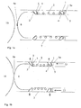
- the invention has two sets of plastic wedges 1, one on each side of a helical spring 2.
- the foremost set can slide up towards an inclined surface 3 on the sensor housing 6 itself, while the rear set can slide up towards a conic ring 4 in the back of the spring 2.
- a flat disk 5 behind the foremost wedge set 1 provides a good and defined sliding surface in the transition towards the helical spring 2.
- An identical flat disk 5 is preferably arranged behind the rear wedge set 1 to provide equal frictional conditions, so that the rear and foremost wedges 1 move equally.
- the primary function of the plastic wedge 1 is centring and supporting, but with substantially lower acoustic impedance than the sensor hosing 6 in metal, they work together as an acoustic barrier towards the mounting frame 7. This contributes to prevent absorption of unwanted noise, so that the sensitivity of the sensor housing 6 is concentrated to the contact point towards the pipe 10, where the measurement medium flows on the inside.
- the sensor housing 6 is shown after it has been guided into the amounting frame 7, but before it is arranged in locking position in towards the pipe 10.
- the sensor housing 6 is surrounded by a non-compressed helical spring 2.
- each end of the spring 2 there are preferably three wedges 1 surrounding the diameter of the sensor housing 6, where the foremost set of wedges 1 are designed to slide up on a inclined surface 3 on the sensor housing 6, and the rear set of wedges 1 is designed to slide up towards a conic ring 4.
- a flat disk 5 is placed behind the foremost set of wedges 1 to provide a defined slide surface in the transition towards the helical spring 2.
- An identical flat disk 5 is preferably arranged behind the rear wedge set 1 to provide equal friction conditions, so that the rear and foremost wedges 1 goes equally.
- An outer cap 8 is preferably mounted around the sensor housing 6, the wedges 1, the conic ring 5 and the flat disks 5 (see figure 3 ).
- the sensor 6a can for instance be a measurement instrument of the same type as shown in the Norwegian patent No 3217
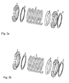
- Figure 2a shows the components constituting the inner mechanism surrounding the sensor housing 6 when the spring 2 is not compressed, and before the sensor housing 6 is put in locked position in towards the pipe 10.
- a helical spring 2 has one set of plastic wedges 1 preferably in each end. Each wedge 1 is rounded on the inside so that these tightly surround the outer diameter of the sensor housing 6.
- a flat disk 5 is placed behind the foremost wedge set 1 as shown in figure 1a to provide a good and defined slide surface in the transition towards the helical spring 2.
- In front of the rear wedges 1 lay a conic ring 4 that these wedges 1 shall slide up on at locking the sensor housing 6 in the mounting frame 7 on the pipe 10.
- FIG 2b the inner mechanism is shown when the spring 2 is compressed (spring compression not shown) and the sensor housing 6 is in locked position in the mounting frame 7 on the pipe 10.
- the components in the inner mechanism are placed in relation to each other in the same way as described above in figure 2a .
- the wedges 1 are spanned out towards the mounting frame 7 as a result of a pressured force 13 from for instance a ROV (see also figure 1b ).
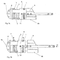
- FIG 3a it is illustrated how the sensor housing 6 and the inner mechanism preferably are surrounded by an outer cap 8, which together with the rear piece 9 comprises a compete sensor 6b.
- the outer cap 8 holds the inner mechanism comprising the sensor housing 6 in place, and protects it from the surroundings.
- the cap 8 has a "window" providing an opening for the protruded parts of the wedges 1 and are held in place themselves by a rear piece 9.
- the rear piece 9 constitutes an extension of the sensor housing 6.
- the cap 8 has protruding locking pins 11 adapted to go into locking tracks 12 in the mounting frame 7 during installation
- Figure 3b illustrates the components of the locking mechanism when it is under influence by a force 13 from for instance a ROV pushing the complete sensor 6b into the mounting frame 7.
- the ROV grips a handle constituting an extension of the outer cap 8 and pushes the whole device in towards the pipe 10.
- the sensor housing 6 with mounted rear piece 9 is not locked to the outer cap 8.
- the spring 8 is compressed by contact between the sensor 6a and the pipe 10, and the wedges 1 slide up the inclined surface 3 and the conic ring 4.
- the protruded part of the wedges 1 will then be pushed out through the "windows" in the outer cap 8, and span out towards the mounting frame 7 so that the sensor housing 6 is centred in the mounting frame 7 with good and solid side support.
- Figure 4 shows a complete sensor 6b in the mounting frame 7 in locked position towards the pipe 10.
- the locking pins 11 on the outer cap 8 will be guided into locking tracks 12 in the mounting frame 7.
- the complete sensor 6b will now be locked with constant spring pressure towards the pipe 10. Sideways, it is now only the plastic wedges 1 spanning in towards the mounting frame 7.
- An alternative way of fastening the sensor 6a in the amounting frame 7 is shown in the Norwegian patent application 2006 1860 .
- the mounting frame 7 is in advance, fixedly mounted on the pipe 10, and is designed so that the complete sensor 6b will fit into and be secured with a robust locking and stable acoustic contact in towards the pipe 10.
- Components as mounting frame 7, sensor housing 7, rear piece 9, outer cap 8, helical spring 2, flat disk 5 and conical ring 4 will preferably be of metal, normally stainless steel or titan, out from requirements to strength and robustness during the conditions and surrounding the equipment will operate.
- the wedges 1 will preferably be of a strong material with substantially lower acoustic impedance than metal, for instance a strong industrial plastic.
- inclined surface 3, flat disk 5 and conic ring 4 could be non-metallic, given that strength and surface friction beyond that maintains the function of the mechanism.
- the wedges 1 can also be of a material or a combination of materials where the considerations regarding large acoustic impendance contrast towards the sensor housing 6 and the mounting frame 7 is not necessarily protected. Wedges 1 of for instance metal will fully maintain the principle and function for attaching sensor 6a, but the function of the wedges 1 as possible acoustic barrier will then be reduced and substantially limited to the effect of a small contact surface towards the mounting frame 7.
- the locking device will be attachable to a pipe 10 with a diameter in the range of 100 - 300 mm, and the mounting frame 7 and the complete sensor 6b will for instance be approximately 700 mm long.
- the mechanical components can be untreated, but they are, especially for metal parts, preferably surface treated for increased resistance towards corrosion and growing.
- metal parts where slide surfaces constitutes it further concerns that they are preferably coated with a material with low surface friction, for instance a Teflon based product. Cathodic protection of the metal parts is also possible.
- a preferred embodiment of the present invention includes wedges 1 designed to together constitute a ring shape tightly surrounding the circumference of the sensor housing 6.
- three wedges 1 are changed around the circumference:
- the wedges 1 are not directly connected to each other or the sensor housing 6, but are held in place by an outer cap 8.
- the inclined surface 3 spanned out by the wedges 1 is also ring shaped, an inclined surface 3 on the sensor housing 6 itself and a conic ring 4, respectively.
- the basic principle for the invention is not dependent on this.
- Alternative embodiments can for instance comprise two or more wedges 1 and accompanying inclined surface 3 not necessarily constituting a ring shape. It is neither a requirement that the inclined surface 3 is designed as a part of the sensor housing 6; it is sufficient that the inclined surface 3 is in mechanical connection with this.
- the wedges 1 can further be held in place by other alternative solutions, for instance with a resilient or elastic connection mutually between the wedges 1, or with other forms of mechanical blocking out from the sensor housing 6.
- alternative embodiments of the invention can be realised without a surrounding outer cap 8.
- a flat disk 5 is placed behind the foremost wedge set 1 to secure a defined glide surface in the transition towards the helical spring 2, and an identical flat disk 5 is arranged behind the rear wedge set to secure identical friction conditions, so that the rear and foremost wedges 1 goes equally.
- the functionality of the invention is not dependent on that such insertions are designed as flat disk 5.
- Alternative embodiments can take several shapes given that the surface laying towards the wedges 1 is adapted to these, and maintains the function as gliding surface, and that the insertions apart from that is mechanical adapted to the adjacent parts. In principle, the rear insertion can possibly also be omitted completely.
- a preferred embodiment of the present invention has at least one set of wedges I in front and at least one set of wedges 1 in the rear edge of the sensor housing 6, for secure sideways support.
- Alternative embodiments can comprise fewer sets of wedges 1 (i.e. one or more) and additional support in another shape, for instance by an elastic connection. The additional support can possibly be attended to by the locking mechanism for spring pressure itself.
Landscapes
- Physics & Mathematics (AREA)
- General Physics & Mathematics (AREA)
- Chemical & Material Sciences (AREA)
- Immunology (AREA)
- Health & Medical Sciences (AREA)
- Analytical Chemistry (AREA)
- Biochemistry (AREA)
- General Health & Medical Sciences (AREA)
- Acoustics & Sound (AREA)
- Life Sciences & Earth Sciences (AREA)
- Pathology (AREA)
- Fluid Mechanics (AREA)
- Electromagnetism (AREA)
- Measuring Fluid Pressure (AREA)
- Investigating Or Analyzing Materials By The Use Of Ultrasonic Waves (AREA)
- Examining Or Testing Airtightness (AREA)
Claims (11)
- Vorrichtung zum Montieren eines Sensors in einem fest montierten Rahmen (7) auf einer Unterwasser-Rohrleitung, umfassend:eine Feder (2),eine Arretiervorrichtung umfassend ein Sensorgehäuse (6), wobei das Sensorgehäuse (6) ausgebildet ist, in den Montagerahmen hineinzupassen und angeordnet ist, im Montagerahmen (7) geführt zu werden, und, wenn beim Gebrauch eine Kraft ausgeübt wird, im Montagerahmen (7) zentriert und gestützt zu werden,dadurch gekennzeichnet, dassdie Feder (2) das Sensorgehäuse (6) umgibt,zumindest ein Keil (1) an einem der Enden der Feder (2) platziert ist,und eine Kante (5a) am anderen Ende der Feder (2) platziert ist,dass die Kraft (13) in der Längsachse des Sensorgehäuses (6) ausgeübt wird, so dass die Feder (2) zusammengedrückt wird und der/die Keil(e) (1) radial gegen den Montagerahmen (7) gespannt werden,wobei der zumindest eine Keil (1) angeordnet ist, als akustische Barriere gegen den Montagerahmen (7) zu wirken,und dass der zumindest eine Keil (1) aus einem Material mit wesentlich geringerer akustischer Impedanz als das metallicsche Sensorgehäuse (6) besteht.
- Vorrichtung nach Anspruch 1, wobei das Sensorgehäuse (6) einen passiven akustischen Sensor (6a) umfasst, welcher im Kontakt mit der Rohrleitung (10) angeordnet ist.
- Vorrichtung nach Anspruch 1, wobei der zumindest eine Keil (1) ausgebildet ist, um gegen eine am Sensorgehäuse (6) herausgearbeitete, geneigte Oberfläche (3) hinauf zu gleiten.
- Vorrichtung nach Anspruch 1, wobei der zumindest eine Keil (1) ausgebildet ist, um gegen eine geneigte Oberfläche auf einem hinter der Feder (2) angeordneten, konischen Ring (4) hinauf zu gleiten.
- Vorrichtung nach Anspruch 1, wobei eine äußere Kappe (8) das Sensorgehäuse (6), die Feder (2) und den/die Keil(e) (1) umgibt, und Löcher aufweist, welche eine Öffnung für den zumindest einen Keil (1) bieten.
- Vorrichtung nach Anspruch 5, wobei ein hinterer Teil (9), welcher eine Verlängerung des Sensorgehäuses (6) ist, die äußere Kappe (8) in Position hält.
- Vorrichtung nach Anspruch 1 und 5, umfassend zumindest zwei Arretierstifte (11) an der äußeren Kappe (8), welche in passenden Arretierspuren (12) im Montagerahmen (7) zur festen Montage des Sensorgehäuses (6) mit konstantem Federdruck in Richtung der Rohrleitung (10) laufen.
- Vorrichtung nach Anspruch 1, wobei der an einem Ende der Feder (2) angeordnete, zumindest eine Keil (1) durch zwei oder mehrere Keilteile gebildet ist, welche entlang des Kreisumfangs des Sensorgehäuses (6) verteilt sind.
- Vorrichtung nach Anspruch 1, wobei eine erste flache Scheibe (5) zwischen dem ersten Keil (1) und der Feder (2) angeordnet ist.
- Vorrichtung nach Anspruch 1, wobei zumindest ein zweiter Keil (1) am zweiten Ende der Feder (2) in Bezug zum zumindest einen Keil (1) angeordnet ist.
- Vorrichtung nach Anspruch 10, wobei eine zweite flache Scheibe (5) zwischen dem zumindest einen zweiten Keil (1) und der Kante (5a) angeordnet ist.
Applications Claiming Priority (2)
| Application Number | Priority Date | Filing Date | Title |
|---|---|---|---|
| NO20065989A NO325937B1 (no) | 2006-12-22 | 2006-12-22 | Lasemekanisme med akustisk barriere for montering av sensor pa ror |
| PCT/NO2007/000436 WO2008079014A2 (en) | 2006-12-22 | 2007-12-11 | Locking mechanism with acoustic barrier for mounting a sensor on a pipe |
Publications (2)
| Publication Number | Publication Date |
|---|---|
| EP2102646A2 EP2102646A2 (de) | 2009-09-23 |
| EP2102646B1 true EP2102646B1 (de) | 2013-07-10 |
Family
ID=39522402
Family Applications (1)
| Application Number | Title | Priority Date | Filing Date |
|---|---|---|---|
| EP07851992.3A Not-in-force EP2102646B1 (de) | 2006-12-22 | 2007-12-11 | Schliessmechanismus mit akustischer Schranke zur Anbringung eines Sensors auf einem Rohr |
Country Status (5)
| Country | Link |
|---|---|
| US (1) | US8127621B2 (de) |
| EP (1) | EP2102646B1 (de) |
| DK (1) | DK2102646T3 (de) |
| NO (1) | NO325937B1 (de) |
| WO (1) | WO2008079014A2 (de) |
Families Citing this family (6)
| Publication number | Priority date | Publication date | Assignee | Title |
|---|---|---|---|---|
| EP2310844A4 (de) * | 2008-07-14 | 2017-02-22 | Exxonmobil Upstream Research Company | Systeme und verfahren und system zur bestimmung der geologischen eigenschaften mittels akustischer analyse |
| DK177040B1 (en) | 2010-04-12 | 2011-02-28 | Miitors Aps | Ultrasonic consumer meter with locking mechanism |
| DE102011090080B4 (de) | 2011-12-29 | 2023-02-02 | Endress + Hauser Flowtec Ag | Austauschbarer Ultraschallwandler für ein Ultraschall-Durchflussmessgerät |
| JP2016001136A (ja) * | 2014-06-12 | 2016-01-07 | 日立Geニュークリア・エナジー株式会社 | 原子力プラントの検査装置取付け方法及び検査装置取付け構造 |
| US11181208B2 (en) | 2018-05-24 | 2021-11-23 | Tdw Delaware, Inc. | Non-invasive pipeline pig signal using vibration sensors |
| CN109270542A (zh) * | 2018-11-16 | 2019-01-25 | 美钻深海能源科技研发(上海)有限公司 | 海洋油气田清管器检测仪 |
Family Cites Families (8)
| Publication number | Priority date | Publication date | Assignee | Title |
|---|---|---|---|---|
| DE19723488A1 (de) * | 1997-06-05 | 1998-12-10 | Elster Produktion Gmbh | Einrichtung zum Befestigen eines Ultraschallwandlers an einem Meßgerät |
| US6112599A (en) | 1998-03-26 | 2000-09-05 | Cement Test Equipment, Inc. | Method and apparatus for measuring a cement sample using a single transducer assembly |
| US7082822B2 (en) * | 2002-04-05 | 2006-08-01 | Vetco Gray Inc. | Internal riser inspection device and methods of using same |
| US6739203B1 (en) * | 2002-08-16 | 2004-05-25 | Feldman Marvin J | Ultrasonic transducer and flow sensor configuration |
| US7058549B2 (en) * | 2003-01-21 | 2006-06-06 | C1Dra Corporation | Apparatus and method for measuring unsteady pressures within a large diameter pipe |
| DE102004052489A1 (de) * | 2004-10-28 | 2006-05-18 | Endress + Hauser Flowtec Ag | Vorrichtung zum Befestigen eines Messsensors auf einer Rohrleitung |
| CA2503275A1 (en) * | 2005-04-07 | 2006-10-07 | Advanced Flow Technologies Inc. | System, method and apparatus for acoustic fluid flow measurement |
| GB0522312D0 (en) * | 2005-11-01 | 2005-12-07 | Cormon Ltd | Monitoring particles in a fluid stream |
-
2006
- 2006-12-22 NO NO20065989A patent/NO325937B1/no not_active IP Right Cessation
-
2007
- 2007-12-11 US US12/520,601 patent/US8127621B2/en not_active Expired - Fee Related
- 2007-12-11 EP EP07851992.3A patent/EP2102646B1/de not_active Not-in-force
- 2007-12-11 WO PCT/NO2007/000436 patent/WO2008079014A2/en not_active Ceased
- 2007-12-11 DK DK07851992.3T patent/DK2102646T3/da active
Also Published As
| Publication number | Publication date |
|---|---|
| EP2102646A2 (de) | 2009-09-23 |
| NO325937B1 (no) | 2008-08-18 |
| US20100077864A1 (en) | 2010-04-01 |
| WO2008079014A2 (en) | 2008-07-03 |
| DK2102646T3 (da) | 2013-09-08 |
| NO20065989L (no) | 2008-06-23 |
| WO2008079014A3 (en) | 2008-08-21 |
| US8127621B2 (en) | 2012-03-06 |
Similar Documents
| Publication | Publication Date | Title |
|---|---|---|
| US8127621B2 (en) | Locking mechanism with acoustic barrier for mounting a sensor on a pipe | |
| US10774639B2 (en) | Downhole local solid particles counting probe, production logging tool comprising the same and sand entry investigation method for hydrocarbon wells | |
| JP4702668B2 (ja) | 流量測定装置 | |
| EP1540272B1 (de) | Überwachung von spannungen in stahlkettensteigrohren | |
| CA3128687C (en) | Structure monitoring | |
| EP1794407B1 (de) | Krümmungsversteifer | |
| JP2005530155A (ja) | 手持ち式装置を用いて流体導管用フィッティング組立体を超音波テストする方法 | |
| CN104344859B (zh) | 换能器系统 | |
| EP2369216B1 (de) | Vorrichtung zur Befestigung einer Vorrichtung an eine kreisförmige Struktur | |
| US20060101914A1 (en) | Acoustic emission inspection of coiled tubing | |
| WO2010034986A1 (en) | Distributed fibre optic diagnosis of riser integrity | |
| US4448062A (en) | Method and apparatus for erosion detection and location in hydrocarbon production systems and the like | |
| GB2549420A (en) | Pipe inspection system, pipe inspection device, pipe inspection method, and recording medium | |
| WO2011039589A8 (en) | System and method for the continuous detection of impacts on pipelines for the transportation of fluids, particularly suitable for underwater pipelines | |
| US20250198875A1 (en) | Sensor with valve release system and method | |
| US11187075B2 (en) | Method for detecting flooding in flexible tubular pipes under high pressure conditions | |
| GB2285510A (en) | Detection apparatus for use with a cylindrical member | |
| JP6366313B2 (ja) | 流体識別装置及び流体識別方法 | |
| US11796487B2 (en) | Device, unit and method for detecting annular flooding with gamma transmission in a flexible pipe | |
| WO2016172161A1 (en) | Subsea multifunctional sensor | |
| EP1819900A1 (de) | Befestigungsmittel für bohrlochmessgerät | |
| CN118980396B (zh) | 水下管道清洁器移动点位的检测装置 | |
| CN223870668U (zh) | 管道含砂检测仪和一种含砂率检测系统 | |
| CN217155338U (zh) | 一种启停传感器 | |
| US20250102089A1 (en) | Sensor quick-connection system and method |
Legal Events
| Date | Code | Title | Description |
|---|---|---|---|
| PUAI | Public reference made under article 153(3) epc to a published international application that has entered the european phase |
Free format text: ORIGINAL CODE: 0009012 |
|
| 17P | Request for examination filed |
Effective date: 20090720 |
|
| AK | Designated contracting states |
Kind code of ref document: A2 Designated state(s): AT BE BG CH CY CZ DE DK EE ES FI FR GB GR HU IE IS IT LI LT LU LV MC MT NL PL PT RO SE SI SK TR |
|
| DAX | Request for extension of the european patent (deleted) | ||
| 17Q | First examination report despatched |
Effective date: 20100408 |
|
| GRAP | Despatch of communication of intention to grant a patent |
Free format text: ORIGINAL CODE: EPIDOSNIGR1 |
|
| GRAS | Grant fee paid |
Free format text: ORIGINAL CODE: EPIDOSNIGR3 |
|
| GRAA | (expected) grant |
Free format text: ORIGINAL CODE: 0009210 |
|
| AK | Designated contracting states |
Kind code of ref document: B1 Designated state(s): AT BE BG CH CY CZ DE DK EE ES FI FR GB GR HU IE IS IT LI LT LU LV MC MT NL PL PT RO SE SI SK TR |
|
| REG | Reference to a national code |
Ref country code: GB Ref legal event code: FG4D |
|
| REG | Reference to a national code |
Ref country code: AT Ref legal event code: REF Ref document number: 621242 Country of ref document: AT Kind code of ref document: T Effective date: 20130715 Ref country code: CH Ref legal event code: EP |
|
| REG | Reference to a national code |
Ref country code: IE Ref legal event code: FG4D |
|
| REG | Reference to a national code |
Ref country code: DE Ref legal event code: R096 Ref document number: 602007031606 Country of ref document: DE Effective date: 20130905 |
|
| REG | Reference to a national code |
Ref country code: DK Ref legal event code: T3 |
|
| REG | Reference to a national code |
Ref country code: NL Ref legal event code: T3 |
|
| PG25 | Lapsed in a contracting state [announced via postgrant information from national office to epo] |
Ref country code: SI Free format text: LAPSE BECAUSE OF FAILURE TO SUBMIT A TRANSLATION OF THE DESCRIPTION OR TO PAY THE FEE WITHIN THE PRESCRIBED TIME-LIMIT Effective date: 20130710 |
|
| REG | Reference to a national code |
Ref country code: AT Ref legal event code: MK05 Ref document number: 621242 Country of ref document: AT Kind code of ref document: T Effective date: 20130710 |
|
| REG | Reference to a national code |
Ref country code: LT Ref legal event code: MG4D |
|
| PG25 | Lapsed in a contracting state [announced via postgrant information from national office to epo] |
Ref country code: AT Free format text: LAPSE BECAUSE OF FAILURE TO SUBMIT A TRANSLATION OF THE DESCRIPTION OR TO PAY THE FEE WITHIN THE PRESCRIBED TIME-LIMIT Effective date: 20130710 Ref country code: CY Free format text: LAPSE BECAUSE OF FAILURE TO SUBMIT A TRANSLATION OF THE DESCRIPTION OR TO PAY THE FEE WITHIN THE PRESCRIBED TIME-LIMIT Effective date: 20130807 Ref country code: LT Free format text: LAPSE BECAUSE OF FAILURE TO SUBMIT A TRANSLATION OF THE DESCRIPTION OR TO PAY THE FEE WITHIN THE PRESCRIBED TIME-LIMIT Effective date: 20130710 Ref country code: BE Free format text: LAPSE BECAUSE OF FAILURE TO SUBMIT A TRANSLATION OF THE DESCRIPTION OR TO PAY THE FEE WITHIN THE PRESCRIBED TIME-LIMIT Effective date: 20130710 Ref country code: PT Free format text: LAPSE BECAUSE OF FAILURE TO SUBMIT A TRANSLATION OF THE DESCRIPTION OR TO PAY THE FEE WITHIN THE PRESCRIBED TIME-LIMIT Effective date: 20131111 Ref country code: IS Free format text: LAPSE BECAUSE OF FAILURE TO SUBMIT A TRANSLATION OF THE DESCRIPTION OR TO PAY THE FEE WITHIN THE PRESCRIBED TIME-LIMIT Effective date: 20131110 Ref country code: SE Free format text: LAPSE BECAUSE OF FAILURE TO SUBMIT A TRANSLATION OF THE DESCRIPTION OR TO PAY THE FEE WITHIN THE PRESCRIBED TIME-LIMIT Effective date: 20130710 |
|
| PG25 | Lapsed in a contracting state [announced via postgrant information from national office to epo] |
Ref country code: ES Free format text: LAPSE BECAUSE OF FAILURE TO SUBMIT A TRANSLATION OF THE DESCRIPTION OR TO PAY THE FEE WITHIN THE PRESCRIBED TIME-LIMIT Effective date: 20131021 Ref country code: LV Free format text: LAPSE BECAUSE OF FAILURE TO SUBMIT A TRANSLATION OF THE DESCRIPTION OR TO PAY THE FEE WITHIN THE PRESCRIBED TIME-LIMIT Effective date: 20130710 Ref country code: FI Free format text: LAPSE BECAUSE OF FAILURE TO SUBMIT A TRANSLATION OF THE DESCRIPTION OR TO PAY THE FEE WITHIN THE PRESCRIBED TIME-LIMIT Effective date: 20130710 Ref country code: PL Free format text: LAPSE BECAUSE OF FAILURE TO SUBMIT A TRANSLATION OF THE DESCRIPTION OR TO PAY THE FEE WITHIN THE PRESCRIBED TIME-LIMIT Effective date: 20130710 Ref country code: GR Free format text: LAPSE BECAUSE OF FAILURE TO SUBMIT A TRANSLATION OF THE DESCRIPTION OR TO PAY THE FEE WITHIN THE PRESCRIBED TIME-LIMIT Effective date: 20131011 |
|
| PG25 | Lapsed in a contracting state [announced via postgrant information from national office to epo] |
Ref country code: CY Free format text: LAPSE BECAUSE OF FAILURE TO SUBMIT A TRANSLATION OF THE DESCRIPTION OR TO PAY THE FEE WITHIN THE PRESCRIBED TIME-LIMIT Effective date: 20130710 |
|
| PG25 | Lapsed in a contracting state [announced via postgrant information from national office to epo] |
Ref country code: CZ Free format text: LAPSE BECAUSE OF FAILURE TO SUBMIT A TRANSLATION OF THE DESCRIPTION OR TO PAY THE FEE WITHIN THE PRESCRIBED TIME-LIMIT Effective date: 20130710 Ref country code: EE Free format text: LAPSE BECAUSE OF FAILURE TO SUBMIT A TRANSLATION OF THE DESCRIPTION OR TO PAY THE FEE WITHIN THE PRESCRIBED TIME-LIMIT Effective date: 20130710 Ref country code: RO Free format text: LAPSE BECAUSE OF FAILURE TO SUBMIT A TRANSLATION OF THE DESCRIPTION OR TO PAY THE FEE WITHIN THE PRESCRIBED TIME-LIMIT Effective date: 20130710 Ref country code: SK Free format text: LAPSE BECAUSE OF FAILURE TO SUBMIT A TRANSLATION OF THE DESCRIPTION OR TO PAY THE FEE WITHIN THE PRESCRIBED TIME-LIMIT Effective date: 20130710 |
|
| PLBE | No opposition filed within time limit |
Free format text: ORIGINAL CODE: 0009261 |
|
| STAA | Information on the status of an ep patent application or granted ep patent |
Free format text: STATUS: NO OPPOSITION FILED WITHIN TIME LIMIT |
|
| PG25 | Lapsed in a contracting state [announced via postgrant information from national office to epo] |
Ref country code: IT Free format text: LAPSE BECAUSE OF FAILURE TO SUBMIT A TRANSLATION OF THE DESCRIPTION OR TO PAY THE FEE WITHIN THE PRESCRIBED TIME-LIMIT Effective date: 20130710 |
|
| 26N | No opposition filed |
Effective date: 20140411 |
|
| REG | Reference to a national code |
Ref country code: DE Ref legal event code: R097 Ref document number: 602007031606 Country of ref document: DE Effective date: 20140411 |
|
| REG | Reference to a national code |
Ref country code: CH Ref legal event code: PL |
|
| PG25 | Lapsed in a contracting state [announced via postgrant information from national office to epo] |
Ref country code: LU Free format text: LAPSE BECAUSE OF FAILURE TO SUBMIT A TRANSLATION OF THE DESCRIPTION OR TO PAY THE FEE WITHIN THE PRESCRIBED TIME-LIMIT Effective date: 20131211 Ref country code: MC Free format text: LAPSE BECAUSE OF FAILURE TO SUBMIT A TRANSLATION OF THE DESCRIPTION OR TO PAY THE FEE WITHIN THE PRESCRIBED TIME-LIMIT Effective date: 20130710 |
|
| REG | Reference to a national code |
Ref country code: IE Ref legal event code: MM4A |
|
| PG25 | Lapsed in a contracting state [announced via postgrant information from national office to epo] |
Ref country code: IE Free format text: LAPSE BECAUSE OF NON-PAYMENT OF DUE FEES Effective date: 20131211 Ref country code: CH Free format text: LAPSE BECAUSE OF NON-PAYMENT OF DUE FEES Effective date: 20131231 Ref country code: LI Free format text: LAPSE BECAUSE OF NON-PAYMENT OF DUE FEES Effective date: 20131231 |
|
| PG25 | Lapsed in a contracting state [announced via postgrant information from national office to epo] |
Ref country code: TR Free format text: LAPSE BECAUSE OF FAILURE TO SUBMIT A TRANSLATION OF THE DESCRIPTION OR TO PAY THE FEE WITHIN THE PRESCRIBED TIME-LIMIT Effective date: 20130710 |
|
| PG25 | Lapsed in a contracting state [announced via postgrant information from national office to epo] |
Ref country code: HU Free format text: LAPSE BECAUSE OF FAILURE TO SUBMIT A TRANSLATION OF THE DESCRIPTION OR TO PAY THE FEE WITHIN THE PRESCRIBED TIME-LIMIT; INVALID AB INITIO Effective date: 20071211 Ref country code: BG Free format text: LAPSE BECAUSE OF FAILURE TO SUBMIT A TRANSLATION OF THE DESCRIPTION OR TO PAY THE FEE WITHIN THE PRESCRIBED TIME-LIMIT Effective date: 20130710 |
|
| PG25 | Lapsed in a contracting state [announced via postgrant information from national office to epo] |
Ref country code: MT Free format text: LAPSE BECAUSE OF FAILURE TO SUBMIT A TRANSLATION OF THE DESCRIPTION OR TO PAY THE FEE WITHIN THE PRESCRIBED TIME-LIMIT Effective date: 20130710 |
|
| REG | Reference to a national code |
Ref country code: FR Ref legal event code: PLFP Year of fee payment: 9 |
|
| REG | Reference to a national code |
Ref country code: FR Ref legal event code: PLFP Year of fee payment: 10 |
|
| REG | Reference to a national code |
Ref country code: FR Ref legal event code: PLFP Year of fee payment: 11 |
|
| PGFP | Annual fee paid to national office [announced via postgrant information from national office to epo] |
Ref country code: NL Payment date: 20191226 Year of fee payment: 13 |
|
| PGFP | Annual fee paid to national office [announced via postgrant information from national office to epo] |
Ref country code: FR Payment date: 20191226 Year of fee payment: 13 |
|
| PGFP | Annual fee paid to national office [announced via postgrant information from national office to epo] |
Ref country code: GB Payment date: 20200102 Year of fee payment: 13 Ref country code: DK Payment date: 20191230 Year of fee payment: 13 Ref country code: DE Payment date: 20191231 Year of fee payment: 13 |
|
| REG | Reference to a national code |
Ref country code: DE Ref legal event code: R119 Ref document number: 602007031606 Country of ref document: DE |
|
| REG | Reference to a national code |
Ref country code: DK Ref legal event code: EBP Effective date: 20201231 |
|
| REG | Reference to a national code |
Ref country code: NL Ref legal event code: MM Effective date: 20210101 |
|
| GBPC | Gb: european patent ceased through non-payment of renewal fee |
Effective date: 20201211 |
|
| PG25 | Lapsed in a contracting state [announced via postgrant information from national office to epo] |
Ref country code: NL Free format text: LAPSE BECAUSE OF NON-PAYMENT OF DUE FEES Effective date: 20210101 |
|
| PG25 | Lapsed in a contracting state [announced via postgrant information from national office to epo] |
Ref country code: FR Free format text: LAPSE BECAUSE OF NON-PAYMENT OF DUE FEES Effective date: 20201231 |
|
| PG25 | Lapsed in a contracting state [announced via postgrant information from national office to epo] |
Ref country code: GB Free format text: LAPSE BECAUSE OF NON-PAYMENT OF DUE FEES Effective date: 20201211 Ref country code: DE Free format text: LAPSE BECAUSE OF NON-PAYMENT OF DUE FEES Effective date: 20210701 |
|
| PG25 | Lapsed in a contracting state [announced via postgrant information from national office to epo] |
Ref country code: DK Free format text: LAPSE BECAUSE OF NON-PAYMENT OF DUE FEES Effective date: 20201231 |