EP2100832B1 - Method of operating a feed device of pieces and feed device, particularly for performing such method - Google Patents
Method of operating a feed device of pieces and feed device, particularly for performing such method Download PDFInfo
- Publication number
- EP2100832B1 EP2100832B1 EP09153630A EP09153630A EP2100832B1 EP 2100832 B1 EP2100832 B1 EP 2100832B1 EP 09153630 A EP09153630 A EP 09153630A EP 09153630 A EP09153630 A EP 09153630A EP 2100832 B1 EP2100832 B1 EP 2100832B1
- Authority
- EP
- European Patent Office
- Prior art keywords
- belt
- pieces
- feed device
- processed
- loading
- Prior art date
- Legal status (The legal status is an assumption and is not a legal conclusion. Google has not performed a legal analysis and makes no representation as to the accuracy of the status listed.)
- Active
Links
- 238000000034 method Methods 0.000 title claims abstract description 12
- 238000004519 manufacturing process Methods 0.000 claims description 20
- 230000007246 mechanism Effects 0.000 claims description 17
- 238000001514 detection method Methods 0.000 claims description 10
- 238000012800 visualization Methods 0.000 claims description 3
- 238000003825 pressing Methods 0.000 description 5
- 238000012545 processing Methods 0.000 description 5
- 230000004888 barrier function Effects 0.000 description 4
- 238000011017 operating method Methods 0.000 description 3
- 230000004913 activation Effects 0.000 description 2
- 238000012986 modification Methods 0.000 description 1
- 230000004048 modification Effects 0.000 description 1
- 230000008569 process Effects 0.000 description 1
Images

Classifications
-
- B—PERFORMING OPERATIONS; TRANSPORTING
- B65—CONVEYING; PACKING; STORING; HANDLING THIN OR FILAMENTARY MATERIAL
- B65G—TRANSPORT OR STORAGE DEVICES, e.g. CONVEYORS FOR LOADING OR TIPPING, SHOP CONVEYOR SYSTEMS OR PNEUMATIC TUBE CONVEYORS
- B65G43/00—Control devices, e.g. for safety, warning or fault-correcting
- B65G43/08—Control devices operated by article or material being fed, conveyed or discharged
-
- B—PERFORMING OPERATIONS; TRANSPORTING
- B23—MACHINE TOOLS; METAL-WORKING NOT OTHERWISE PROVIDED FOR
- B23P—METAL-WORKING NOT OTHERWISE PROVIDED FOR; COMBINED OPERATIONS; UNIVERSAL MACHINE TOOLS
- B23P19/00—Machines for simply fitting together or separating metal parts or objects, or metal and non-metal parts, whether or not involving some deformation; Tools or devices therefor so far as not provided for in other classes
- B23P19/001—Article feeders for assembling machines
-
- B—PERFORMING OPERATIONS; TRANSPORTING
- B65—CONVEYING; PACKING; STORING; HANDLING THIN OR FILAMENTARY MATERIAL
- B65G—TRANSPORT OR STORAGE DEVICES, e.g. CONVEYORS FOR LOADING OR TIPPING, SHOP CONVEYOR SYSTEMS OR PNEUMATIC TUBE CONVEYORS
- B65G47/00—Article or material-handling devices associated with conveyors; Methods employing such devices
- B65G47/34—Devices for discharging articles or materials from conveyor
- B65G47/46—Devices for discharging articles or materials from conveyor and distributing, e.g. automatically, to desired points
- B65G47/51—Devices for discharging articles or materials from conveyor and distributing, e.g. automatically, to desired points according to unprogrammed signals, e.g. influenced by supply situation at destination
- B65G47/5104—Devices for discharging articles or materials from conveyor and distributing, e.g. automatically, to desired points according to unprogrammed signals, e.g. influenced by supply situation at destination for articles
- B65G47/5109—Devices for discharging articles or materials from conveyor and distributing, e.g. automatically, to desired points according to unprogrammed signals, e.g. influenced by supply situation at destination for articles first In - First Out systems: FIFO
- B65G47/5113—Devices for discharging articles or materials from conveyor and distributing, e.g. automatically, to desired points according to unprogrammed signals, e.g. influenced by supply situation at destination for articles first In - First Out systems: FIFO using endless conveyors
Definitions
- the present invention relates to a method of feeding pieces to a production machine according to the preamble of claim 1, such as a press, a machine tool and similar, to a feed device according to the preamble of claim 2, particularly for executing such method, and to a production system according to the preamble of claim 12.
- a highly automised production line contains a device for feeding the pieces, a pick-up device and a production machine. See, for example, US 4,557,655 , which discloses a method of operating a feed device, a feed device and a production system according to the preamble of claims 1, 2 and 12 respectively.
- a conveyor belt feed device is loaded with pieces by an operator; the pieces, transported by the conveyor are taken to a robot; the robot picks up a piece to be processed and puts it in a press, for performance of the scheduled process. On completion of processing, the robot picks up the piece and puts it on another conveyor belt for transport towards further production phases.
- the belt advances while it is loaded with pieces by the operator, continuously or discontinuously, depending on the requirements of the production line, this way new pieces to be processed reach the robot at one end of the belt, while another end of the belt, near the operator is freed so as to load more pieces.
- the operator for example to perform another task, to go for a break or when finishing a shift leaves the belt belt area and returns only after a period of time, of varying length, during which an extensive loading area of the belt without new pieces to be processed has formed.
- the purpose of the present invention is to create an operating method of a feed device which overcomes the drawbacks spoken of in relation to the known art.
- the present invention is embodied by a method of operating a feed device as stated in claim 1; a feed device as stated in claim 2 and a production system comprising such a feed device as stated in claim 12.
- FIG. 1 shows an overhead view of a production comprising a feed device of the present invention, according to a preferred embodiment
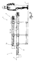
- figure 2 shows a lateral view of the feed device of the system in figure 1 .
- reference numeral 1 globally denotes a system for the processing of pieces to be processed and for obtaining processed pieces F.
- the system 1 comprises a feed device 2 able to feed pieces to be processed; the feed device 2 is of the belt type, in other words comprising at least one belt for the transport of pieces to be processed placed on it.
- the feed device has a loading area 4 and a pick-up area 6, distanced along a belt axis X coinciding with the direction of advancement of the pieces on the belt.
- the system 1 comprises a pick-up device 8, for instance a robot, and a production machine 10, for instance a press.
- the pick-up device 8 is positioned close to the pick-up area 6 of the feed device 2, and is able to pick up the pieces to be processed and offer them to the production machine 10 for processing.
- the system 1 comprises a transport device 12, for instance a belt, for the transport of the processed pieces towards subsequent production phases.
- the robot picks up the processed piece and puts it on the belt of the transport device 12, to be taken away.
- the system 1 comprises safety barriers 14 which prevent access of the operator in the vicinity of the robot or of the press.
- the feed device 2 protrudes with its loading area outside the area defined by the safety barriers 14, so that the operator can load the pieces to be processed, while the pick-up area 6 is inside the defined area.
- the feed device 2 extends along the belt axis X between the loading area 4 and the pick-up area 6.
- the feed device 2 comprises a first motorised belt 20, for instance horizontal, and a second motorised belt 22, parallel to the first, which extends from the loading area 4 to the pick-up area 6.
- the first belt is positioned above the second belt, that is it vertically overlays the second belt, but is distanced from it so as to allow the transit of the pieces to be processed between said belts.
- the belts 20, 22 of the feed device are motorised so as to advance from the loading area towards the pick-up area and vice versa.
- the belts 20, 22 are motorised so that, upon command, the pieces advance from the loading area towards the pick-up area or move backwards from the pick-up area towards the loading area.
- the feed device 2 comprises a belt selection mechanism, which can be operated by the operator and is able to select the belt from which the pick-up device picks up the piece to be processed, choosing from said belts 20, 22.
- the loading belt is the belt from which the robot picks up the pieces to be processed and delivers them to the press.
- the robot could pick up said pieces from the first belt 20 or from the second belt 22.
- the belt selection mechanism can be operated by the operator to select the belt 20, 22 from which the robot picks up the piece to be processed.
- the belt selection mechanism comprises a single belt selection button, operatively connected to a selection control unit.
- the selection control unit recognises the loading belt and, in the presence of the signal coming from the belt selection button, designates the loading belt as the passive belt and the passive belt as the new loading belt.
- the former passive belt becomes the new loading belt and the former loading belt becomes the new passive belt.
- the belt selection mechanism comprises a first button associated with the first belt and a second button associated with the second belt; by pressing the first or second button the respective belt is designated as the loading belt.
- the other belt that is the belt from which the robot does not pick up the pieces to be processed, is called the passive belt.
- the feed device 2 comprises a return mechanism, which can be operated by the operator, able to make the passive belt return, that is advance from the pick-up area towards the loading area.
- the return mechanism comprises a return button, positioned close to the loading area; when the button is pressed, the passive belt starts a return movement.
- the feed device 2 comprises powered means of advancement, operatively connected to the motors of the belts 20, 22, which can be operated by the operator and able to make the passive belt advance, in other words move from the loading area towards the pick-up area.
- said powered means of advancement comprise a pedal, for instance protruding from the floor; when the pedal is pressed by the operator, the passive belt advances.
- the feed device 2 comprises means of detection able to detect the presence of pieces to be processed in the pick-up area; specifically, the feed device 2 comprises first means of detection associated with the first belt 20 and second means of detection associated with the second belt 22.
- Said means of detection are operatively connected to the motor mechanism of the belts 20, 22, to order advancement of the loading belt when no pieces to be processed are detected in the pick-up area and to order stopping of the belts, (for instance, both the loading belt and the passive belt) when pieces to be processed are detected in the pick-up area.
- the means of detection are operatively connected to the powered means of advancement, so that if the powered means of advancement are activated (and the operator therefore orders advancement of the passive belt), but the means of detection detects pieces in the pick-up area of the passive belt (which might therefore fall as a result of further advancement), the activation of the powered means of advancement is ignored.
- the feed device 2 comprises means of visualisation able to acquire the image of the piece to be processed in the pick-up area.
- Said means of visualisation are operatively connected to the pick-up device to control its configuration, trajectory and movement so as to efficiently pick up the piece to be processed.
- the feed device 2 comprises an automatic designation device, operatively connected to the belt selection mechanism, able to detect the presence of at least one piece on the loading belt and able to interact with the belt selection mechanism to automatically designate the passive belt as the new loading belt should the loading belt not have any more pieces to be processed on it.
- the designated loading belt is the first belt 20 and that the second belt 22 is therefore the passive belt.
- the passive belt that is the second belt 22
- the passive belt is full of pieces to be processed in the pick-up area.
- the second means of detection detect the pieces to be processed in the pick-up area of the second belt 22 and order it to stop.
- the operator loads the first belt 20; when the piece to be processed has been picked up, the first means of detection detects the absence of pieces to be processed in the pick-up area 6 of the first belt and orders its advancement.
- the pick-up device 8 will therefore pick up the next piece to be processed from the second belt 22 and no longer from the first belt 20.
- the return button is released causing the passive belt, that is the first belt 20 to stop.
- the operator recommences loading of the passive belt, that is the first belt 20, which tends to progressively advance, at the operator's command, by activation of the powered means of advancement (preferably by pressing the pedal) until the first means of detection detect pieces to be processed in the pick-up area.
- the pick-up device 8 has continued to pick up pieces to be processed from the loading belt 22, without halting production.
- first belt 20 and the second belt 22 are alongside and close to each other, for instance at the same height; according to a further embodiment, the first belt 20 is alongside but distanced from the second belt, so that the operator can stand between them.
- the automatic designation device detects the absence of pieces on the loading belt' and interacts with the belt selection mechanism so that automatically, that is without intervention of the operator, the passive belt is designated as the new loading belt and the loading belt as the new passive belt.
- the passive belt therefore also acts as a reserve, or depot of pieces to be processed.
- the invention prevents the operator from having to adopt dangerous positions, for instance trying to fill the empty area of the conveyor belt and passing the safety barriers.
- the invention permits a considerable lengthening of the period of autonomy of the production line.
- the invention permits management of production lines with high or low pieces to be processed, in relation to their tendency to fall over as a result of movement of the belt.
- the selection mechanisms prevent errors when choosing the loading belt, by being respectively associated to the belt selected as loading belt.
Landscapes
- Engineering & Computer Science (AREA)
- Mechanical Engineering (AREA)
- Control Of Conveyors (AREA)
- Electrical Discharge Machining, Electrochemical Machining, And Combined Machining (AREA)
- Sewing Machines And Sewing (AREA)
- Control Of Multiple Motors (AREA)
- Feeding Of Articles To Conveyors (AREA)
Abstract
Description
- The present invention relates to a method of feeding pieces to a production machine according to the preamble of claim 1, such as a press, a machine tool and similar, to a feed device according to the preamble of
claim 2, particularly for executing such method, and to a production system according to the preamble ofclaim 12. - Usually, a highly automised production line contains a device for feeding the pieces, a pick-up device and a production machine. See, for example,
US 4,557,655 , which discloses a method of operating a feed device, a feed device and a production system according to the preamble ofclaims - In another example, a conveyor belt feed device is loaded with pieces by an operator; the pieces, transported by the conveyor are taken to a robot; the robot picks up a piece to be processed and puts it in a press, for performance of the scheduled process. On completion of processing, the robot picks up the piece and puts it on another conveyor belt for transport towards further production phases.
- The belt advances while it is loaded with pieces by the operator, continuously or discontinuously, depending on the requirements of the production line, this way new pieces to be processed reach the robot at one end of the belt, while another end of the belt, near the operator is freed so as to load more pieces.
- Often the operator, for example to perform another task, to go for a break or when finishing a shift leaves the belt belt area and returns only after a period of time, of varying length, during which an extensive loading area of the belt without new pieces to be processed has formed.
- When processing of the pieces already loaded on the belt is finished and the belt arrives at the robot without any pieces, production halts until the arrival of a new piece loaded by the operator upon his return.
- Generally speaking, once back at the belt the operator is unable to fill the empty part of the belt since this has already passed the safety barrier preventing access, in the vicinity of the robot.
- If, however, the loading area is accessible by the operator, in any case the loading operation forces him to adopt a dangerous position.
- The purpose of the present invention is to create an operating method of a feed device which overcomes the drawbacks spoken of in relation to the known art.
- It is also the purpose of the present invention to create a feed device, particularly for performing the aforesaid operating method. The present invention is embodied by a method of operating a feed device as stated in claim 1; a feed device as stated in
claim 2 and a production system comprising such a feed device as stated inclaim 12. - Further characteristics and advantages of the operating method and of the feed device will be evident from the description below, made by way of a non-limiting example, according to the attached figures, wherein:
- -
figure 1 shows an overhead view of a production comprising a feed device of the present invention, according to a preferred embodiment; - -
figure 2 shows a lateral view of the feed device of the system infigure 1 . - With reference to the attached figures, reference numeral 1 globally denotes a system for the processing of pieces to be processed and for obtaining processed pieces F.
- The system 1 comprises a
feed device 2 able to feed pieces to be processed; thefeed device 2 is of the belt type, in other words comprising at least one belt for the transport of pieces to be processed placed on it. - Specifically, the feed device has a
loading area 4 and a pick-up area 6, distanced along a belt axis X coinciding with the direction of advancement of the pieces on the belt. - Furthermore, the system 1 comprises a pick-
up device 8, for instance a robot, and a production machine 10, for instance a press. - The pick-up
device 8 is positioned close to the pick-up area 6 of thefeed device 2, and is able to pick up the pieces to be processed and offer them to the production machine 10 for processing. - Furthermore, according to a preferred embodiment, the system 1 comprises a
transport device 12, for instance a belt, for the transport of the processed pieces towards subsequent production phases. - For instance, when the press has finished processing a piece, the robot picks up the processed piece and puts it on the belt of the
transport device 12, to be taken away. - According to a preferred embodiment, the system 1 comprises safety barriers 14 which prevent access of the operator in the vicinity of the robot or of the press.
- For instance, the
feed device 2 protrudes with its loading area outside the area defined by the safety barriers 14, so that the operator can load the pieces to be processed, while the pick-up area 6 is inside the defined area. - The
feed device 2 extends along the belt axis X between theloading area 4 and the pick-up area 6. - Preferably, the
feed device 2 comprises a firstmotorised belt 20, for instance horizontal, and a secondmotorised belt 22, parallel to the first, which extends from theloading area 4 to the pick-up area 6. - For instance, the first belt is positioned above the second belt, that is it vertically overlays the second belt, but is distanced from it so as to allow the transit of the pieces to be processed between said belts.
- The
belts - In other words, the
belts - The
feed device 2 comprises a belt selection mechanism, which can be operated by the operator and is able to select the belt from which the pick-up device picks up the piece to be processed, choosing fromsaid belts - In other words, the loading belt is the belt from which the robot picks up the pieces to be processed and delivers them to the press. The robot could pick up said pieces from the
first belt 20 or from thesecond belt 22. The belt selection mechanism can be operated by the operator to select thebelt - According to a preferred embodiment, the belt selection mechanism comprises a single belt selection button, operatively connected to a selection control unit.
- The selection control unit recognises the loading belt and, in the presence of the signal coming from the belt selection button, designates the loading belt as the passive belt and the passive belt as the new loading belt.
- In other words, by pressing the belt selection button, the former passive belt becomes the new loading belt and the former loading belt becomes the new passive belt.
- Advantageously, this means that the new loading belt can be designated without error by the operator, in that said operator does not need to make a choice but only to press the belt selection button.
- According to a further embodiment variation, the belt selection mechanism comprises a first button associated with the first belt and a second button associated with the second belt; by pressing the first or second button the respective belt is designated as the loading belt. The other belt, that is the belt from which the robot does not pick up the pieces to be processed, is called the passive belt.
- Furthermore, the
feed device 2 comprises a return mechanism, which can be operated by the operator, able to make the passive belt return, that is advance from the pick-up area towards the loading area. - For instance, the return mechanism comprises a return button, positioned close to the loading area; when the button is pressed, the passive belt starts a return movement.
- Furthermore, the
feed device 2 comprises powered means of advancement, operatively connected to the motors of thebelts - According to a preferred embodiment, said powered means of advancement comprise a pedal, for instance protruding from the floor; when the pedal is pressed by the operator, the passive belt advances.
- Furthermore, the
feed device 2 comprises means of detection able to detect the presence of pieces to be processed in the pick-up area; specifically, thefeed device 2 comprises first means of detection associated with thefirst belt 20 and second means of detection associated with thesecond belt 22. - Said means of detection are operatively connected to the motor mechanism of the
belts - According to a preferred embodiment, the means of detection are operatively connected to the powered means of advancement, so that if the powered means of advancement are activated (and the operator therefore orders advancement of the passive belt), but the means of detection detects pieces in the pick-up area of the passive belt (which might therefore fall as a result of further advancement), the activation of the powered means of advancement is ignored.
- According to a preferred embodiment, moreover, the
feed device 2 comprises means of visualisation able to acquire the image of the piece to be processed in the pick-up area. - Said means of visualisation are operatively connected to the pick-up device to control its configuration, trajectory and movement so as to efficiently pick up the piece to be processed.
- According to a preferred embodiment, the
feed device 2 comprises an automatic designation device, operatively connected to the belt selection mechanism, able to detect the presence of at least one piece on the loading belt and able to interact with the belt selection mechanism to automatically designate the passive belt as the new loading belt should the loading belt not have any more pieces to be processed on it. - To better illustrate the method of operation according to the present invention, we will assume that the designated loading belt is the
first belt 20 and that thesecond belt 22 is therefore the passive belt. - Preparatively, the passive belt, that is the
second belt 22, is full of pieces to be processed in the pick-up area. The second means of detection detect the pieces to be processed in the pick-up area of thesecond belt 22 and order it to stop. - Normally, the operator loads the
first belt 20; when the piece to be processed has been picked up, the first means of detection detects the absence of pieces to be processed in the pick-up area 6 of the first belt and orders its advancement. - In the
loading area 4 of thefirst belt 20 an empty area therefore forms, where the operator puts a further piece to be processed. - Assuming that the operator is absent for a period of time, for instance to perform another task, to go for a break or when finishing a shift, while production continues and the
first belt 20 advances, a progressively larger empty area forms in the loading area. - When the operator returns to the feed device, he activates the belt selection mechanism (preferably by pressing the single belt selection button), selecting the
second belt 22 as the loading belt: the pick-updevice 8 will therefore pick up the next piece to be processed from thesecond belt 22 and no longer from thefirst belt 20. - The operator then activates the return mechanism, for instance by pressing the return button, causing the backward movement of the
first belt 20, until the empty area is sufficiently reduced. - At this point, the return button is released causing the passive belt, that is the
first belt 20 to stop. - The operator recommences loading of the passive belt, that is the
first belt 20, which tends to progressively advance, at the operator's command, by activation of the powered means of advancement (preferably by pressing the pedal) until the first means of detection detect pieces to be processed in the pick-up area. - In the meantime, the pick-
up device 8 has continued to pick up pieces to be processed from theloading belt 22, without halting production. - According to further embodiment variations, the
first belt 20 and thesecond belt 22 are alongside and close to each other, for instance at the same height; according to a further embodiment, thefirst belt 20 is alongside but distanced from the second belt, so that the operator can stand between them. - In the case in which the operator is absent for such a long time that all the pieces present on the loading belt are finished, the automatic designation device detects the absence of pieces on the loading belt' and interacts with the belt selection mechanism so that automatically, that is without intervention of the operator, the passive belt is designated as the new loading belt and the loading belt as the new passive belt.
- Advantageously, the passive belt therefore also acts as a reserve, or depot of pieces to be processed.
- Innovatively, the method of operating a feed device of pieces and said feed device of pieces, overcome the problem of production interruptions caused by lack of pieces on the feed belts.
- Advantageously, moreover, the invention prevents the operator from having to adopt dangerous positions, for instance trying to fill the empty area of the conveyor belt and passing the safety barriers.
- According to a further advantageous aspect, the invention permits a considerable lengthening of the period of autonomy of the production line.
- According to yet a further advantageous aspect, the invention permits management of production lines with high or low pieces to be processed, in relation to their tendency to fall over as a result of movement of the belt.
- Advantageously, moreover, the selection mechanisms prevent errors when choosing the loading belt, by being respectively associated to the belt selected as loading belt.
- It is clear that a person skilled in the art may make modifications to the method and device according to the present invention, so as to satisfy contingent and specific requirements while remaining within the scope of protection as defined by the appended claims.
Claims (12)
- Method of operating a feed device (2) of pieces (F), comprising, in succession, the phases of:- feeding the pieces (F) to be processed to a pick-up device (8) by means of a first belt (20); characterized in that it comprises the phases of :- detecting an empty area without any pieces on said first belt;- manually selecting a second belt (22);- feeding the pieces (F) to be processed to said pick-up device (B) solely by means of said second belt;- making the first belt (20) move backwards to reduce the empty area;- loading the pieces (F) to be processed on the first belt (20), in the reduced empty area.
- Feed device (2) of pieces (F), comprising :- a first motorised belt (20) to feed the pieces;- a second motorised belt (22) to feed the pieces; characterized in that it further comprises :- a belt selection mechanism able to manually select, from said first (20) and second belt (22), a loading belt, the other belt being defined a passive belt;- a return mechanism able to make said passive belt move backwards to reduce the empty area without any pieces (F) to be processed.
- Feed device according to claim 2, wherein said first belt (20) vertically overlays the second belt (22).
- Feed device according to claim 2, wherein said first belt (20) is alongside the second belt (22) and distanced from it to accommodate an operator between them.
- Feed device according to claim 4, wherein said first (20) and second (22) belt are close to each other.
- Feed device according to any of the claims from 2 to 5, comprising means of detection for the detect of pieces (F) to be processed in the pick-up area (6) of said belts (20,22).
- Feed device according to any of the claims from 2 to 6, wherein said belt selection mechanism comprises a single button operatively connected to a control unit for the selection of the loading belt only.
- Feed device according to any of claims from 2 to 7, wherein said return mechanism comprises a button.
- Feed device according to any of claims from 2 to 8, comprising powered means of advancement able to be manually activated to order advancement of the passive belt.
- Feed device according to any of the claims from 2 to 9, comprising an automatic designation device able to detect the absence of pieces (F) on the loading belt and to automatically designate a new loading belt.
- Feed device according to any of the claims from 2 to 10, comprising means of visualisation able to acquire the image of the of the piece (F) to be processed.
- Production system (1) comprising:- a feed device (2);- a pick-up device (8), for instance a robot;- a production machine (10), for instance a press, characterized in that the feed device (2) is according to any of the claims from 2 to 11.
Priority Applications (1)
| Application Number | Priority Date | Filing Date | Title |
|---|---|---|---|
| EP10172545A EP2251281B1 (en) | 2008-03-11 | 2009-02-25 | Method of operating a feed device of pieces and feed device, particularly for performing such method |
Applications Claiming Priority (1)
| Application Number | Priority Date | Filing Date | Title |
|---|---|---|---|
| IT000050A ITBS20080050A1 (en) | 2008-03-11 | 2008-03-11 | METHOD OF DRIVING A PART FEEDING DEVICE AND FEEDING DEVICE, IN PARTICULAR FOR THE EXECUTION OF THESE METHOD |
Related Child Applications (1)
| Application Number | Title | Priority Date | Filing Date |
|---|---|---|---|
| EP10172545.5 Division-Into | 2010-08-11 |
Publications (2)
| Publication Number | Publication Date |
|---|---|
| EP2100832A1 EP2100832A1 (en) | 2009-09-16 |
| EP2100832B1 true EP2100832B1 (en) | 2011-04-27 |
Family
ID=40292694
Family Applications (2)
| Application Number | Title | Priority Date | Filing Date |
|---|---|---|---|
| EP09153630A Active EP2100832B1 (en) | 2008-03-11 | 2009-02-25 | Method of operating a feed device of pieces and feed device, particularly for performing such method |
| EP10172545A Active EP2251281B1 (en) | 2008-03-11 | 2009-02-25 | Method of operating a feed device of pieces and feed device, particularly for performing such method |
Family Applications After (1)
| Application Number | Title | Priority Date | Filing Date |
|---|---|---|---|
| EP10172545A Active EP2251281B1 (en) | 2008-03-11 | 2009-02-25 | Method of operating a feed device of pieces and feed device, particularly for performing such method |
Country Status (5)
| Country | Link |
|---|---|
| EP (2) | EP2100832B1 (en) |
| AT (1) | ATE507171T1 (en) |
| DE (1) | DE602009001121D1 (en) |
| ES (1) | ES2365658T3 (en) |
| IT (1) | ITBS20080050A1 (en) |
Families Citing this family (4)
| Publication number | Priority date | Publication date | Assignee | Title |
|---|---|---|---|---|
| ITRE20090114A1 (en) * | 2009-12-04 | 2011-06-05 | Zecchetti Srl | DEVICE AND METHOD OF STORAGE OF PRODUCTS FOR A WORKING LINE FOR MIDDLE PRODUCTS |
| KR101933746B1 (en) | 2011-08-11 | 2018-12-28 | 몰 벨팅 시스템즈, 인코포레이티드. | Cyclo reducer arrangement |
| CN107553145A (en) * | 2017-10-16 | 2018-01-09 | 李刚 | A kind of multiple operation robot automation production line and automatic production method |
| CN114043204B (en) * | 2021-12-22 | 2023-04-25 | 东莞市德镌精密设备有限公司 | LOGO kludge that precision is high |
Family Cites Families (2)
| Publication number | Priority date | Publication date | Assignee | Title |
|---|---|---|---|---|
| SE430682B (en) * | 1982-05-06 | 1983-12-05 | Asea Ab | SET AND DEVICE TO PROVIDE AND REMOVE DETAILS AT A ROBOT OPERATED MACHINE |
| ES2266680T3 (en) * | 2003-04-17 | 2007-03-01 | Cfs Buhl Gmbh | MACHINE FOR SEALING CONTAINERS, THROUGH THE APPLICATION OF A COATING FILM. |
-
2008
- 2008-03-11 IT IT000050A patent/ITBS20080050A1/en unknown
-
2009
- 2009-02-25 AT AT09153630T patent/ATE507171T1/en not_active IP Right Cessation
- 2009-02-25 EP EP09153630A patent/EP2100832B1/en active Active
- 2009-02-25 ES ES09153630T patent/ES2365658T3/en active Active
- 2009-02-25 EP EP10172545A patent/EP2251281B1/en active Active
- 2009-02-25 DE DE602009001121T patent/DE602009001121D1/en active Active
Also Published As
| Publication number | Publication date |
|---|---|
| EP2251281B1 (en) | 2012-12-26 |
| ITBS20080050A1 (en) | 2009-09-12 |
| EP2251281A1 (en) | 2010-11-17 |
| ES2365658T3 (en) | 2011-10-07 |
| DE602009001121D1 (en) | 2011-06-09 |
| ATE507171T1 (en) | 2011-05-15 |
| EP2100832A1 (en) | 2009-09-16 |
Similar Documents
| Publication | Publication Date | Title |
|---|---|---|
| EP2100832B1 (en) | Method of operating a feed device of pieces and feed device, particularly for performing such method | |
| US6923614B2 (en) | Magazine lumber feeder | |
| US20090113853A1 (en) | Package unbundling system | |
| EP2841261B1 (en) | Intelligent automatic transport arrangement for package manufacturing | |
| DE112016005250B4 (en) | robot | |
| US20080267757A1 (en) | Apparatus for Forming Stacks of Panels and Feeding them to a User Station | |
| US20140083310A1 (en) | Method for actuating the band driving device of a strapping machine and corresponding strapping machine | |
| JPH1177402A (en) | Bar material supply machine for machine tool, automatic lathe in particular | |
| US11890732B2 (en) | Binding machine | |
| US8931322B2 (en) | Coil handling system and method | |
| US12006709B2 (en) | Binding machine | |
| KR101420577B1 (en) | Automatic bundle packing machine | |
| US20110301801A1 (en) | Horizontal order-picker | |
| TWI803694B (en) | Strapping machine | |
| US10315449B2 (en) | Thread sewing machine | |
| JPH084865B2 (en) | Coil-shaped rebar bending device, extraction method, caravan car, and coil-shaped rebar bending process | |
| EP1726544A1 (en) | Conveyor device with buffer system | |
| KR100784605B1 (en) | System and method for protecting the bundle former | |
| CN112425013B (en) | Cable processor system and method for removing one or more cables from a take-out trough of a cable processor system | |
| EP3079846B1 (en) | Bar feeding method and device | |
| US7055673B2 (en) | Device for feeding threadlike objects such as hooks for garment hangers, a system for conveying and feeding garment hangers and a method for feeding threadlike objects | |
| JPH11130014A (en) | Bundling machine and upper pressing device therefor | |
| CN116176916A (en) | Strapping machine | |
| RU2801194C2 (en) | Strapping machine | |
| US20240254786A1 (en) | Binding machine |
Legal Events
| Date | Code | Title | Description |
|---|---|---|---|
| PUAI | Public reference made under article 153(3) epc to a published international application that has entered the european phase |
Free format text: ORIGINAL CODE: 0009012 |
|
| AK | Designated contracting states |
Kind code of ref document: A1 Designated state(s): AT BE BG CH CY CZ DE DK EE ES FI FR GB GR HR HU IE IS IT LI LT LU LV MC MK MT NL NO PL PT RO SE SI SK TR |
|
| AX | Request for extension of the european patent |
Extension state: AL BA RS |
|
| 17P | Request for examination filed |
Effective date: 20100218 |
|
| AKX | Designation fees paid |
Designated state(s): AT BE BG CH CY CZ DE DK EE ES FI FR GB GR HR HU IE IS IT LI LT LU LV MC MK MT NL NO PL PT RO SE SI SK TR |
|
| 17Q | First examination report despatched |
Effective date: 20100506 |
|
| R17C | First examination report despatched (corrected) |
Effective date: 20100506 |
|
| GRAP | Despatch of communication of intention to grant a patent |
Free format text: ORIGINAL CODE: EPIDOSNIGR1 |
|
| GRAS | Grant fee paid |
Free format text: ORIGINAL CODE: EPIDOSNIGR3 |
|
| GRAA | (expected) grant |
Free format text: ORIGINAL CODE: 0009210 |
|
| AK | Designated contracting states |
Kind code of ref document: B1 Designated state(s): AT BE BG CH CY CZ DE DK EE ES FI FR GB GR HR HU IE IS IT LI LT LU LV MC MK MT NL NO PL PT RO SE SI SK TR |
|
| REG | Reference to a national code |
Ref country code: GB Ref legal event code: FG4D |
|
| REG | Reference to a national code |
Ref country code: CH Ref legal event code: EP |
|
| REG | Reference to a national code |
Ref country code: IE Ref legal event code: FG4D |
|
| REF | Corresponds to: |
Ref document number: 602009001121 Country of ref document: DE Date of ref document: 20110609 Kind code of ref document: P |
|
| REG | Reference to a national code |
Ref country code: DE Ref legal event code: R096 Ref document number: 602009001121 Country of ref document: DE Effective date: 20110609 |
|
| REG | Reference to a national code |
Ref country code: SE Ref legal event code: TRGR |
|
| REG | Reference to a national code |
Ref country code: NL Ref legal event code: VDEP Effective date: 20110427 |
|
| LTIE | Lt: invalidation of european patent or patent extension |
Effective date: 20110427 |
|
| REG | Reference to a national code |
Ref country code: ES Ref legal event code: FG2A Ref document number: 2365658 Country of ref document: ES Kind code of ref document: T3 Effective date: 20111007 |
|
| PG25 | Lapsed in a contracting state [announced via postgrant information from national office to epo] |
Ref country code: PT Free format text: LAPSE BECAUSE OF FAILURE TO SUBMIT A TRANSLATION OF THE DESCRIPTION OR TO PAY THE FEE WITHIN THE PRESCRIBED TIME-LIMIT Effective date: 20110829 Ref country code: LT Free format text: LAPSE BECAUSE OF FAILURE TO SUBMIT A TRANSLATION OF THE DESCRIPTION OR TO PAY THE FEE WITHIN THE PRESCRIBED TIME-LIMIT Effective date: 20110427 Ref country code: NO Free format text: LAPSE BECAUSE OF FAILURE TO SUBMIT A TRANSLATION OF THE DESCRIPTION OR TO PAY THE FEE WITHIN THE PRESCRIBED TIME-LIMIT Effective date: 20110727 Ref country code: HR Free format text: LAPSE BECAUSE OF FAILURE TO SUBMIT A TRANSLATION OF THE DESCRIPTION OR TO PAY THE FEE WITHIN THE PRESCRIBED TIME-LIMIT Effective date: 20110427 |
|
| PG25 | Lapsed in a contracting state [announced via postgrant information from national office to epo] |
Ref country code: SI Free format text: LAPSE BECAUSE OF FAILURE TO SUBMIT A TRANSLATION OF THE DESCRIPTION OR TO PAY THE FEE WITHIN THE PRESCRIBED TIME-LIMIT Effective date: 20110427 Ref country code: LV Free format text: LAPSE BECAUSE OF FAILURE TO SUBMIT A TRANSLATION OF THE DESCRIPTION OR TO PAY THE FEE WITHIN THE PRESCRIBED TIME-LIMIT Effective date: 20110427 Ref country code: GR Free format text: LAPSE BECAUSE OF FAILURE TO SUBMIT A TRANSLATION OF THE DESCRIPTION OR TO PAY THE FEE WITHIN THE PRESCRIBED TIME-LIMIT Effective date: 20110728 Ref country code: FI Free format text: LAPSE BECAUSE OF FAILURE TO SUBMIT A TRANSLATION OF THE DESCRIPTION OR TO PAY THE FEE WITHIN THE PRESCRIBED TIME-LIMIT Effective date: 20110427 Ref country code: IS Free format text: LAPSE BECAUSE OF FAILURE TO SUBMIT A TRANSLATION OF THE DESCRIPTION OR TO PAY THE FEE WITHIN THE PRESCRIBED TIME-LIMIT Effective date: 20110827 Ref country code: BE Free format text: LAPSE BECAUSE OF FAILURE TO SUBMIT A TRANSLATION OF THE DESCRIPTION OR TO PAY THE FEE WITHIN THE PRESCRIBED TIME-LIMIT Effective date: 20110427 Ref country code: CY Free format text: LAPSE BECAUSE OF FAILURE TO SUBMIT A TRANSLATION OF THE DESCRIPTION OR TO PAY THE FEE WITHIN THE PRESCRIBED TIME-LIMIT Effective date: 20110427 Ref country code: AT Free format text: LAPSE BECAUSE OF FAILURE TO SUBMIT A TRANSLATION OF THE DESCRIPTION OR TO PAY THE FEE WITHIN THE PRESCRIBED TIME-LIMIT Effective date: 20110427 |
|
| PG25 | Lapsed in a contracting state [announced via postgrant information from national office to epo] |
Ref country code: NL Free format text: LAPSE BECAUSE OF FAILURE TO SUBMIT A TRANSLATION OF THE DESCRIPTION OR TO PAY THE FEE WITHIN THE PRESCRIBED TIME-LIMIT Effective date: 20110427 |
|
| PG25 | Lapsed in a contracting state [announced via postgrant information from national office to epo] |
Ref country code: EE Free format text: LAPSE BECAUSE OF FAILURE TO SUBMIT A TRANSLATION OF THE DESCRIPTION OR TO PAY THE FEE WITHIN THE PRESCRIBED TIME-LIMIT Effective date: 20110427 Ref country code: CZ Free format text: LAPSE BECAUSE OF FAILURE TO SUBMIT A TRANSLATION OF THE DESCRIPTION OR TO PAY THE FEE WITHIN THE PRESCRIBED TIME-LIMIT Effective date: 20110427 |
|
| PG25 | Lapsed in a contracting state [announced via postgrant information from national office to epo] |
Ref country code: SK Free format text: LAPSE BECAUSE OF FAILURE TO SUBMIT A TRANSLATION OF THE DESCRIPTION OR TO PAY THE FEE WITHIN THE PRESCRIBED TIME-LIMIT Effective date: 20110427 Ref country code: PL Free format text: LAPSE BECAUSE OF FAILURE TO SUBMIT A TRANSLATION OF THE DESCRIPTION OR TO PAY THE FEE WITHIN THE PRESCRIBED TIME-LIMIT Effective date: 20110427 |
|
| PLBE | No opposition filed within time limit |
Free format text: ORIGINAL CODE: 0009261 |
|
| STAA | Information on the status of an ep patent application or granted ep patent |
Free format text: STATUS: NO OPPOSITION FILED WITHIN TIME LIMIT |
|
| 26N | No opposition filed |
Effective date: 20120130 |
|
| REG | Reference to a national code |
Ref country code: DE Ref legal event code: R097 Ref document number: 602009001121 Country of ref document: DE Effective date: 20120130 |
|
| PG25 | Lapsed in a contracting state [announced via postgrant information from national office to epo] |
Ref country code: MC Free format text: LAPSE BECAUSE OF NON-PAYMENT OF DUE FEES Effective date: 20120229 |
|
| REG | Reference to a national code |
Ref country code: IE Ref legal event code: MM4A |
|
| PG25 | Lapsed in a contracting state [announced via postgrant information from national office to epo] |
Ref country code: IE Free format text: LAPSE BECAUSE OF NON-PAYMENT OF DUE FEES Effective date: 20120225 |
|
| PG25 | Lapsed in a contracting state [announced via postgrant information from national office to epo] |
Ref country code: MK Free format text: LAPSE BECAUSE OF FAILURE TO SUBMIT A TRANSLATION OF THE DESCRIPTION OR TO PAY THE FEE WITHIN THE PRESCRIBED TIME-LIMIT Effective date: 20110427 |
|
| PGFP | Annual fee paid to national office [announced via postgrant information from national office to epo] |
Ref country code: FR Payment date: 20130321 Year of fee payment: 5 Ref country code: ES Payment date: 20130207 Year of fee payment: 5 Ref country code: SE Payment date: 20130222 Year of fee payment: 5 |
|
| PG25 | Lapsed in a contracting state [announced via postgrant information from national office to epo] |
Ref country code: BG Free format text: LAPSE BECAUSE OF FAILURE TO SUBMIT A TRANSLATION OF THE DESCRIPTION OR TO PAY THE FEE WITHIN THE PRESCRIBED TIME-LIMIT Effective date: 20110727 |
|
| PG25 | Lapsed in a contracting state [announced via postgrant information from national office to epo] |
Ref country code: MT Free format text: LAPSE BECAUSE OF FAILURE TO SUBMIT A TRANSLATION OF THE DESCRIPTION OR TO PAY THE FEE WITHIN THE PRESCRIBED TIME-LIMIT Effective date: 20110427 |
|
| REG | Reference to a national code |
Ref country code: CH Ref legal event code: PL |
|
| GBPC | Gb: european patent ceased through non-payment of renewal fee |
Effective date: 20130225 |
|
| PG25 | Lapsed in a contracting state [announced via postgrant information from national office to epo] |
Ref country code: LI Free format text: LAPSE BECAUSE OF NON-PAYMENT OF DUE FEES Effective date: 20130228 Ref country code: CH Free format text: LAPSE BECAUSE OF NON-PAYMENT OF DUE FEES Effective date: 20130228 |
|
| PG25 | Lapsed in a contracting state [announced via postgrant information from national office to epo] |
Ref country code: GB Free format text: LAPSE BECAUSE OF NON-PAYMENT OF DUE FEES Effective date: 20130225 |
|
| PG25 | Lapsed in a contracting state [announced via postgrant information from national office to epo] |
Ref country code: TR Free format text: LAPSE BECAUSE OF FAILURE TO SUBMIT A TRANSLATION OF THE DESCRIPTION OR TO PAY THE FEE WITHIN THE PRESCRIBED TIME-LIMIT Effective date: 20110427 |
|
| PG25 | Lapsed in a contracting state [announced via postgrant information from national office to epo] |
Ref country code: LU Free format text: LAPSE BECAUSE OF NON-PAYMENT OF DUE FEES Effective date: 20120225 |
|
| PG25 | Lapsed in a contracting state [announced via postgrant information from national office to epo] |
Ref country code: HU Free format text: LAPSE BECAUSE OF FAILURE TO SUBMIT A TRANSLATION OF THE DESCRIPTION OR TO PAY THE FEE WITHIN THE PRESCRIBED TIME-LIMIT Effective date: 20090225 |
|
| REG | Reference to a national code |
Ref country code: SE Ref legal event code: EUG |
|
| REG | Reference to a national code |
Ref country code: FR Ref legal event code: ST Effective date: 20141031 |
|
| PG25 | Lapsed in a contracting state [announced via postgrant information from national office to epo] |
Ref country code: SE Free format text: LAPSE BECAUSE OF NON-PAYMENT OF DUE FEES Effective date: 20140226 |
|
| PG25 | Lapsed in a contracting state [announced via postgrant information from national office to epo] |
Ref country code: FR Free format text: LAPSE BECAUSE OF NON-PAYMENT OF DUE FEES Effective date: 20140228 |
|
| REG | Reference to a national code |
Ref country code: ES Ref legal event code: FD2A Effective date: 20150327 |
|
| PG25 | Lapsed in a contracting state [announced via postgrant information from national office to epo] |
Ref country code: ES Free format text: LAPSE BECAUSE OF NON-PAYMENT OF DUE FEES Effective date: 20140226 |
|
| PGFP | Annual fee paid to national office [announced via postgrant information from national office to epo] |
Ref country code: DE Payment date: 20240219 Year of fee payment: 16 |
|
| PGFP | Annual fee paid to national office [announced via postgrant information from national office to epo] |
Ref country code: IT Payment date: 20231205 Year of fee payment: 16 |