EP2099583B1 - Verfahren und vorrichtung zur entfernung von stiften in einem geschlossenen raum - Google Patents
Verfahren und vorrichtung zur entfernung von stiften in einem geschlossenen raum Download PDFInfo
- Publication number
- EP2099583B1 EP2099583B1 EP07857433.2A EP07857433A EP2099583B1 EP 2099583 B1 EP2099583 B1 EP 2099583B1 EP 07857433 A EP07857433 A EP 07857433A EP 2099583 B1 EP2099583 B1 EP 2099583B1
- Authority
- EP
- European Patent Office
- Prior art keywords
- pin
- water jet
- tool
- jet tool
- water
- Prior art date
- Legal status (The legal status is an assumption and is not a legal conclusion. Google has not performed a legal analysis and makes no representation as to the accuracy of the status listed.)
- Not-in-force
Links
Images


Classifications
-
- B—PERFORMING OPERATIONS; TRANSPORTING
- B23—MACHINE TOOLS; METAL-WORKING NOT OTHERWISE PROVIDED FOR
- B23P—METAL-WORKING NOT OTHERWISE PROVIDED FOR; COMBINED OPERATIONS; UNIVERSAL MACHINE TOOLS
- B23P6/00—Restoring or reconditioning objects
- B23P6/002—Repairing turbine components, e.g. moving or stationary blades, rotors
-
- B—PERFORMING OPERATIONS; TRANSPORTING
- B24—GRINDING; POLISHING
- B24C—ABRASIVE OR RELATED BLASTING WITH PARTICULATE MATERIAL
- B24C1/00—Methods for use of abrasive blasting for producing particular effects; Use of auxiliary equipment in connection with such methods
- B24C1/04—Methods for use of abrasive blasting for producing particular effects; Use of auxiliary equipment in connection with such methods for treating only selected parts of a surface, e.g. for carving stone or glass
- B24C1/045—Methods for use of abrasive blasting for producing particular effects; Use of auxiliary equipment in connection with such methods for treating only selected parts of a surface, e.g. for carving stone or glass for cutting
-
- B—PERFORMING OPERATIONS; TRANSPORTING
- B26—HAND CUTTING TOOLS; CUTTING; SEVERING
- B26F—PERFORATING; PUNCHING; CUTTING-OUT; STAMPING-OUT; SEVERING BY MEANS OTHER THAN CUTTING
- B26F3/00—Severing by means other than cutting; Apparatus therefor
- B26F3/004—Severing by means other than cutting; Apparatus therefor by means of a fluid jet
-
- F—MECHANICAL ENGINEERING; LIGHTING; HEATING; WEAPONS; BLASTING
- F01—MACHINES OR ENGINES IN GENERAL; ENGINE PLANTS IN GENERAL; STEAM ENGINES
- F01D—NON-POSITIVE DISPLACEMENT MACHINES OR ENGINES, e.g. STEAM TURBINES
- F01D5/00—Blades; Blade-carrying members; Heating, heat-insulating, cooling or antivibration means on the blades or the members
- F01D5/005—Repairing methods or devices
-
- F—MECHANICAL ENGINEERING; LIGHTING; HEATING; WEAPONS; BLASTING
- F01—MACHINES OR ENGINES IN GENERAL; ENGINE PLANTS IN GENERAL; STEAM ENGINES
- F01D—NON-POSITIVE DISPLACEMENT MACHINES OR ENGINES, e.g. STEAM TURBINES
- F01D5/00—Blades; Blade-carrying members; Heating, heat-insulating, cooling or antivibration means on the blades or the members
- F01D5/30—Fixing blades to rotors; Blade roots ; Blade spacers
- F01D5/3053—Fixing blades to rotors; Blade roots ; Blade spacers by means of pins
-
- Y—GENERAL TAGGING OF NEW TECHNOLOGICAL DEVELOPMENTS; GENERAL TAGGING OF CROSS-SECTIONAL TECHNOLOGIES SPANNING OVER SEVERAL SECTIONS OF THE IPC; TECHNICAL SUBJECTS COVERED BY FORMER USPC CROSS-REFERENCE ART COLLECTIONS [XRACs] AND DIGESTS
- Y10—TECHNICAL SUBJECTS COVERED BY FORMER USPC
- Y10T—TECHNICAL SUBJECTS COVERED BY FORMER US CLASSIFICATION
- Y10T83/00—Cutting
- Y10T83/04—Processes
- Y10T83/0591—Cutting by direct application of fluent pressure to work
-
- Y—GENERAL TAGGING OF NEW TECHNOLOGICAL DEVELOPMENTS; GENERAL TAGGING OF CROSS-SECTIONAL TECHNOLOGIES SPANNING OVER SEVERAL SECTIONS OF THE IPC; TECHNICAL SUBJECTS COVERED BY FORMER USPC CROSS-REFERENCE ART COLLECTIONS [XRACs] AND DIGESTS
- Y10—TECHNICAL SUBJECTS COVERED BY FORMER USPC
- Y10T—TECHNICAL SUBJECTS COVERED BY FORMER US CLASSIFICATION
- Y10T83/00—Cutting
- Y10T83/364—By fluid blast and/or suction
Definitions
- the invention pertains to a method and device for the controlled mechanical removal of pins in a confined access space. It pertains in particular, but not exclusively, to the removal of press-fit pins in steam turbine blading.
- Steam turbine blades are attached to the rotor, among others, by means of a straddle-type blade root and press-fit pins placed in boreholes extending through the blade root and rotor.
- the pins Prior to their placement in the boreholes, the pins are for example cooled to low temperatures, e.g. by means of liquid nitrogen. Thus slightly reduced in size, they are then pressed into the borehole with heavy-duty tools, which results in a tight, high-tension press-fit between the pin and the turbine rotor and blade root.
- the pins are removed "in situ” thus avoiding transporting and segmenting the turbine rotor.
- Each pin is removed individually using standard, handheld drills with hard metal or diamond drill bits. Particular care must be taken in order to prevent any damage to the material surrounding the borehole so that a high quality press-fit of the pin fastening the new blade to be mounted can be assured.
- Both methods, rotor segmentation and “in situ” removal, are time-consuming and costly procedures.
- GB 2 349 111 discloses a general use of water jets (as opposed to EDM), for drilling of cooling air holes in turbine airfoils.
- the cooling air holes are drilled prior to mounting the airfoil on the rotor.
- the application thus has no particular access space requirement.
- US 2005/0050706 discloses the use of a water jet for the cutting of a rivet in steelwork.
- the jet is used to cut a circular ring in the rivet in order to extricate the rivet.
- the water jet apparatus comprises an extensive assembly of large size and thus unsuitable for drilling in a confined space.
- EP 1 524 059 discloses a method of removing a pin surrounded by solid material in a confide space by an EDM tool.
- GB 1 148 072 discloses the features of the preamble of claim 11.
- the method according to the invention is presented in claim 1 and includes drilling or cutting of a pin surrounded by material using a water jet.
- the water jet is directed onto the surface of the pin to be removed and directed along a controlled path.
- the method includes the use of a water jet tool having a supply line for water, a main body, and a nozzle that is arranged at an angle with respect to the longitudinal axis of the main body of the water jet tool and water supply line.
- the water jet produced by the nozzle is directed over one or more portions of the surface of the pin to be removed removing one or more portions of the pin. Each portion removed includes at least two sections of the boundary between the pin and the surrounding material.
- the portions removed from the pin divide the pin into two or more fragments thereby releasing the tension in the pin surrounded by the material and effecting a separation of the fragments from the surrounding material.
- the one or more portions of material removed from the pin touch the interface or boundary between the pin and the surrounding material at a minimal number of points and over a minimal extent of the boundary. The amount of boundary touched by the removed portions is only large enough to effect a division of the pin into portions.
- the one or more portions removed from the pin have a cross-section at the surface of the pin extending essentially along the diameter of the pin's surface, dividing it into two parts.
- the one or more portions removed from the pin have a cross-section at its surface having a star-like shape, where the points of the star touch the surrounding material. In this case, the pin to be removed is divided into three or more parts, depending on the number of points on the "star-like" shape.
- the portion removed from the pin has a polygon shape.
- an abrasive material is added to the flow of water within the water jet tool, such as for example garnet or "sand-like" substances.
- a further exemplary method includes attaching the water jet tool to the surrounding material using permanent magnets. This allows a time efficient placement of the tool to the surrounding ferromagnetic material and requires no further power or tool. Following the removal of a pin, it is quickly and easily removed and placed at a new location for the removal of a further pin. In order to facilitate the precise placement of the tool with respect to the pin to be removed, the tool is arranged on a displacement table with at least two degrees of freedom of movement. The displacement table is attached to the surrounding metallic material by means of permanent magnets.
- clamps such as mechanical, spring-loaded, pneumatic or hydraulic clamps, belts or any other means of positioning the nozzle. These may be used in the case of non-magnetic surrounding material or permanent magnets cannot be used for another reason, e.g. space reasons.
- a water jet tool used to perform the method according to the invention is presented in claim 11 and comprises a nozzle having a longitudinal axis that is angled with respect to the longitudinal axis of the tool main body.
- the overall length of the water jet tool in line with the water jet directed onto the pin to be removed is thereby reduced in comparison to water jet tools of the state of the art. This facilitates access within a constricted space.
- the water jet tool according to the invention comprises a supply line for abrasive material connected to the water line within the tool that is connected to the water flow within the tool following the angle between the main and the nozzle. This facilitates a design of the angled portion independent of the abrasive, i.e. that withstands the pressure of the water alone.
- a water jet tool assembly for removing the pin includes two or more water jet tool nozzles, each having a water supply line connected to a common single water supply and pump.
- Each water jet tool is attached, for example, by permanent magnets to the surrounding material such that two or more pins can be removed at the same time.
- the method according to the invention allows an "in-situ" removal of a pin in constricted space facilitated by the angled water jet tool nozzle. Compared to water jet tools of the state of the art, it has a reduced overall length in line with the water jet impinging onto the pin to be removed. This allows its application in much smaller access spaces. Transport and segmentation of the surrounding material or machine is no longer necessary in order to enlarge the access space.
- the method furthermore allows removal of pins with minimal damage to the surrounding material. Problems associated with EDM are entirely avoided.
- the material removal method is also performed within a significantly shorter time span compared to the mentioned methods of the state of the art.
- the method according to the invention using the angled water jet tool is applicable to the drilling or cutting of pins of any solid material.
- Such solids include steels, metals, metal alloys, wood, ceramics, fiber reinforced composites, and others. It is particularly applicable in turbine maintenance such as the removal of press-fit pins on steam turbine blading. It is equally applicable to the maintenance of any other machine with confined space for access.
- Such applications include, for example, turbine maintenance, generator maintenance, drilling operations in boilers or double-hulls of ships.
- Blades are secured in blade rows to a steam turbine rotor by various means.
- Figure 1 shows a portion of a steam turbine rotor 1, on which blade rows are secured by means of a turbine rotor wheel 2.
- Each blade 3 is equipped with a blade platform 4 and a two-part blade root 5.
- Each of the radially extending parts of the root 5 is placed in a circumferential groove 6 in the turbine wheel 2.
- one or more pins 7 are placed in bores 8 extending through the turbine wheel 2 and the blade root 5. The pins are placed in the bores by a high-tension press-fit.
- FIG. 2 shows two turbine wheels 2, with blade rows 3 secured to them by their roots 5 in grooves 6.
- the space between the blade rows is confined so that a conventional tool cannot be directed straight at a pin or does not fit at all.
- the press-fit pins are removed by means of water jet tools as illustrated in principle in figure 2 .
- the water jet tools 10 each include a nozzle 11 arranged at an angle with respect to the longitudinal axis of the main tool body 12 and the water supply lines 13.
- the arrangement of the nozzle enables the placement of the entire tool within the confined space and allows the removal of pins and blades without segmenting the turbine rotor.
- Both water supply lines 13 are preferably connected to one single water pump.
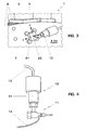
- Figure 3 shows the arrangement of a water jet tool 10 according to the invention on a displacement table 20 and the fastening of the displacement table to the turbine wheel 2 by means of permanent magnets 21.
- the use of permanent magnets 21 allows an efficient fastening and removal of the water jet tool from one pin to the next without the need of any further tools or power.
- the displacement table facilitates the precise placement of the water jet in two directions x and y with respect to the pin to be removed.
- clamps or belts may be used instead of using permanent magnets for the fastening of the water jet tool onto the surrounding material. All these fastening method are applicable to a water jet tool with or without displacement table. This facilitates fastening in situations when permanent magnets are not applicable because the surrounding material is not suitable or there is not sufficient space for the placement of magnets.
- Figure 4 shows, in more detail, a water jet tool 10 used in the method according to the invention and as shown for example in figure 2 and 3 .
- It includes a water supply line 13, a main body 12, and the nozzle 11 arranged at an angle to the main body 12. Preferably it is at a right angle to the body 12 thus minimizing the length of the tool in line with the water jet to be directed onto the pin.
- the nozzle 11 is made of standard high-strength stainless steel. Its internal elements include a standard sapphire nozzle, focalizing tube, and abrasive mixing chamber.
- a supply line 14 for the addition of abrasives to the water is connected to the water flow within the water jet tool at a point following the angle between the main body and the nozzle 11.
- Figure 5a to c show examples of pin portions 30 removed from a pin 31 surrounded by metallic material 32.
- the removal of portions 30 releases the tension of the press-fit between the pin 31 and the surrounding solid material 32, here a metallic material, and allows fragments of the pin to detach from the surrounding material.
- Figures 5a and b show the removal of portions 30 in the shape of a star touching the boundary 34 between the pin 31 and the surrounding material 32 in four and three points, respectively. By this means, the pin is dissected into several fragments 33, whereby the surrounding material is only minimally affected.
- Figure 5c shows a strip of material 30 removed from the pin 31 extending across the diameter of the pin. It is the simplest shape of material portion removed effecting fragmentation of the pin 31 into two parts.
- Figure 6 shows the fragmentation and detachment of the fragments 33 from the surrounding material 32.
Landscapes
- Engineering & Computer Science (AREA)
- Mechanical Engineering (AREA)
- General Engineering & Computer Science (AREA)
- Life Sciences & Earth Sciences (AREA)
- Forests & Forestry (AREA)
- Perforating, Stamping-Out Or Severing By Means Other Than Cutting (AREA)
Claims (12)
- Verfahren zum Entfernen eines Stiftes (31), der von einem festen Material (32) umgeben ist, durch Bohren oder Schneiden in einem engen Raum,
gekennzeichnet durch
Verwenden eines Wasserstrahls aus einem Wasserstrahlwerkzeug (10), der auf die Oberfläche des Stifts (31) gelenkt wird, und Lenken des Strahls entlang eines gesteuerten Weges, wobei das Wasserstrahlwerkzeug (10) eine Wasserversorgungsleitung (13), einen Hauptkörper (12) und eine Düse (11), die in Bezug auf die Längsachse des Hauptkörpers (12) in einem Winkel angeordnet ist, aufweist,
Lenken des Wasserstrahls über einen oder über mehrere Abschnitte (30) der Oberfläche des Stifts (31), wobei ein oder mehrere Abschnitte (30) des Stifts (31) entfernt werden und jeder des einen oder der mehreren entfernten Abschnitte (30) die Grenze des Stifts (31) zu dem umgebenden festen Material (32) an mindestens zwei Orten enthält, und wobei der zu entfernende Stift (31) in zwei oder mehr Fragmente (33) geteilt wird. - Verfahren nach Anspruch 1,
dadurch gekennzeichnet, dass
der Abschnitt oder die Abschnitte (30) des Stifts (31), die durch das Wasserstrahlwerkzeug (10) entfernt worden sind, einen minimalen Teil der Grenze (34) zwischen dem Stift (31) und dem umgebenden festen Material (32), der groß genug ist, um eine Teilung des Stifts (31) zu bewirken, enthalten. - Verfahren nach Anspruch 1,
dadurch gekennzeichnet, dass
der eine oder die mehreren Abschnitte (30), die von dem Stift (31) entfernt worden sind, eine Querschnittsfläche an der Oberfläche des Stifts (31) aufweisen, die sich im Wesentlichen entlang des Durchmessers der Oberfläche des Stifts (31) erstreckt. - Verfahren nach Anspruch 1,
dadurch gekennzeichnet, dass
der eine oder die mehreren Abschnitte (30), die von dem Stift (31) entfernt worden sind, eine Querschnittsfläche an der Oberfläche des Stifts (31) aufweisen, die eine sternähnliche Form oder eine Polygonform aufweist, wobei die Punkte des Sterns oder des Polygons die Grenze zwischen dem Stift (31) und dem umgebenden festen Material (32) berühren. - Verfahren nach Anspruch 1,
gekennzeichnet durch
Zuführen eines abschleifenden Materials zu dem Wasserfluss innerhalb des Wasserstrahlwerkzeugs (10) an einem Punkt, der auf den Winkel zwischen dem Hauptkörper (12) und der Düse (11) folgt. - Verfahren nach Anspruch 1,
gekennzeichnet durch
Befestigen des Wasserstrahlwerkzeugs (10) an dem umgebenden festen Material (32) mittels von Permanentmagneten (21). - Verfahren nach Anspruch 1,
gekennzeichnet durch
Befestigen des Wasserstrahlwerkzeugs (10) an dem umgebenden festen Material (32) mittels von Klemmen oder Riemen. - Verfahren nach Anspruch 1,
gekennzeichnet durch
Anordnen des Wasserstrahlwerkzeugs (10) auf einem Verschiebungstisch (20) mit mindestens zwei Freiheitsgraden der Bewegung. - Verfahren nach Anspruch 8,
gekennzeichnet durch
Befestigen des Verschiebungstisches (20) an dem umgebenden festen Material (32) mittels von Permanentmagneten (21), Klemmen oder Riemen. - Verfahren nach einem der Ansprüche 1 bis 9,
dadurch gekennzeichnet, dass
der Stift (31) ein durch Presspassung eingepresster Stift (7) ist, der dazu verwendet wird, um eine Schaufel (3) an dem Turbinenrad (2) eines Turbinenrotors (1) zu befestigen. - Wasserstrahlwerkzeug (10), um das Verfahren nach Anspruch 1 durchzuführen, wobei das Wasserstrahlwerkzeug eine Wasserversorgungsleitung (13), einen Hauptkörper (12) und eine Düse (11), die eine Längsachse aufweist, die in Bezug auf die Längsachse des Hauptkörpers (12) des Werkzeugs (10) angewinkelt ist, umfasst,
und ferner eine Leitung (14) für abschleifendes Material umfasst, die innerhalb des Wasserstrahlwerkzeugs (10) an einem Punkt nach dem angewinkelten Abschnitt der Düse (11) mit dem Wasserfluss verbunden ist, dadurch gekennzeichnet, dass es einen Verschiebungstisch mit mindestens zwei Freiheitsgraden, auf dem das Wasserstrahlwerkzeug befestigt ist, und Permanentmagnete, Klemmen oder Riemen zum Befestigen des Verschiebungstisches an einer Oberfläche, die einen Bereich umgibt, an den ein Fluss von der Düse gelenkt wird, aufweist. - Wasserstrahlwerkzeuganordnung,
die zwei oder mehr Wasserstrahlwerkzeuge (10) nach Anspruch 11 umfasst, wobei jedes Wasserstrahlwerkzeug (10) eine Versorgungsleitung für Wasser (13) aufweist, die mit einer gemeinsamen einzelnen Wasserleitung und mit einer Pumpe verbunden ist.
Priority Applications (1)
| Application Number | Priority Date | Filing Date | Title |
|---|---|---|---|
| EP07857433.2A EP2099583B1 (de) | 2007-01-08 | 2007-12-12 | Verfahren und vorrichtung zur entfernung von stiften in einem geschlossenen raum |
Applications Claiming Priority (3)
| Application Number | Priority Date | Filing Date | Title |
|---|---|---|---|
| EP20070100237 EP1941967A1 (de) | 2007-01-08 | 2007-01-08 | Verfahren und Vorrichtung zur Entfernung eines Stifts in engem Raum |
| EP07857433.2A EP2099583B1 (de) | 2007-01-08 | 2007-12-12 | Verfahren und vorrichtung zur entfernung von stiften in einem geschlossenen raum |
| PCT/EP2007/063763 WO2008083889A1 (en) | 2007-01-08 | 2007-12-12 | Method and device for pin removal in a confined space |
Publications (2)
| Publication Number | Publication Date |
|---|---|
| EP2099583A1 EP2099583A1 (de) | 2009-09-16 |
| EP2099583B1 true EP2099583B1 (de) | 2014-01-15 |
Family
ID=37963703
Family Applications (2)
| Application Number | Title | Priority Date | Filing Date |
|---|---|---|---|
| EP20070100237 Withdrawn EP1941967A1 (de) | 2007-01-08 | 2007-01-08 | Verfahren und Vorrichtung zur Entfernung eines Stifts in engem Raum |
| EP07857433.2A Not-in-force EP2099583B1 (de) | 2007-01-08 | 2007-12-12 | Verfahren und vorrichtung zur entfernung von stiften in einem geschlossenen raum |
Family Applications Before (1)
| Application Number | Title | Priority Date | Filing Date |
|---|---|---|---|
| EP20070100237 Withdrawn EP1941967A1 (de) | 2007-01-08 | 2007-01-08 | Verfahren und Vorrichtung zur Entfernung eines Stifts in engem Raum |
Country Status (5)
| Country | Link |
|---|---|
| US (2) | US7628678B2 (de) |
| EP (2) | EP1941967A1 (de) |
| CN (1) | CN101219545B (de) |
| CA (1) | CA2674569C (de) |
| WO (1) | WO2008083889A1 (de) |
Families Citing this family (7)
| Publication number | Priority date | Publication date | Assignee | Title |
|---|---|---|---|---|
| US8257044B2 (en) * | 2007-09-11 | 2012-09-04 | Hitachi, Ltd. | Steam turbine rotor blade assembly |
| CH700883A1 (de) | 2009-04-22 | 2010-10-29 | Alstom Technology Ltd | Verfahren zum herstellen eines mit einem schlitz als testriss versehenen körpers. |
| US8695216B2 (en) | 2011-12-27 | 2014-04-15 | Climax Portable Machine Tools, Inc. | Machine tools and methods for machining turbine rotor assemblies |
| EP2617540B1 (de) * | 2012-01-20 | 2014-03-19 | Alstom Technology Ltd | Prallplatte zum Steuern von Hochdruck-Flüssigkeitsstrahlen |
| US9278462B2 (en) | 2013-11-20 | 2016-03-08 | General Electric Company | Backstrike protection during machining of cooling features |
| US20150160644A1 (en) * | 2013-12-05 | 2015-06-11 | General Electric Company | Repair method, system for automatic locating and clearing and tool for automated locating and modifying |
| US12343806B2 (en) | 2022-09-15 | 2025-07-01 | General Electric Company | Apparatus and method for guiding a cutting/drilling tool and capturing generated foreign material |
Citations (1)
| Publication number | Priority date | Publication date | Assignee | Title |
|---|---|---|---|---|
| US5499519A (en) * | 1993-12-22 | 1996-03-19 | Societe Nationale D'etude Et De Construction De Moteurs D'aviation "Snecma" | Device for shot-blasting surfaces inaccessible by a straight pipe |
Family Cites Families (32)
| Publication number | Priority date | Publication date | Assignee | Title |
|---|---|---|---|---|
| US2813710A (en) * | 1954-02-04 | 1957-11-19 | John H Ferguson | Magnetically supported guide bar for torches and the like |
| GB1148072A (en) * | 1966-04-25 | 1969-04-10 | Woma App Bau W Maasberg & Co G | A method of mechanically finishing workpieces |
| US3864876A (en) * | 1974-04-15 | 1975-02-11 | Wheelabrator Frye Inc | Fixture for a blast cleaning machine |
| US4111490A (en) * | 1975-09-05 | 1978-09-05 | Liesveld Daniel J | Method and apparatus for channel cutting of hard materials using high velocity fluid jets |
| US4174571A (en) * | 1978-07-28 | 1979-11-20 | Dentron, Inc. | Method for cleaning teeth |
| US4319436A (en) * | 1980-02-04 | 1982-03-16 | Wheelabrator-Frye, Inc. | Portable blasting device and sealing means |
| JPS58200002A (ja) * | 1982-05-17 | 1983-11-21 | Toshiba Corp | タ−ビン動翼の結合分解方法 |
| EP0127380B1 (de) * | 1983-05-20 | 1988-10-12 | Micron Co., Ltd. | Spülgerät zum Behandeln von Zahnwurzelkanälen |
| US4768709A (en) * | 1986-10-29 | 1988-09-06 | Fluidyne Corporation | Process and apparatus for generating particulate containing fluid jets |
| US4815241A (en) * | 1986-11-24 | 1989-03-28 | Whitemetal Inc. | Wet jet blast nozzle |
| US4848042A (en) * | 1987-09-09 | 1989-07-18 | Ltv Aerospace And Defense Company | Fluid jet cutting system with standoff control |
| FR2636400B1 (fr) * | 1988-09-12 | 1990-12-14 | Serfi | Vanne haute pression utilisable notamment dans un outil de coupe a jet fluide |
| FR2643004B1 (fr) * | 1989-02-13 | 1994-06-17 | Hurel Dubois Avions | Procede de percage d'une plaque a tres grande densite de trous et de configuration quelconque, et produits resultants |
| ES2099712T3 (es) * | 1989-07-21 | 1997-06-01 | Australian Stone Tech | Procedimiento y aparato para el corte de materiales erosivos utilizando un medio de agua de alta presion. |
| FR2736563B1 (fr) * | 1995-07-11 | 1997-08-22 | Comadur Sa | Buse de decoupage a jet de fluide devie |
| US5795214A (en) * | 1997-03-07 | 1998-08-18 | Cold Jet, Inc. | Thrust balanced turn base for the nozzle assembly of an abrasive media blasting system |
| CN2313709Y (zh) * | 1997-12-04 | 1999-04-14 | 山东省博兴县华兴企业集团公司 | 水切割磨料射流装置 |
| IT250346Y1 (it) * | 1998-05-05 | 2003-09-03 | Atom Spa | Gruppo di taglio a getto d'acqua a teste multiple. in particolare perpelle, cuoio e materiali sintetici. |
| DE19917611A1 (de) | 1999-04-19 | 2000-10-26 | Abb Alstom Power Ch Ag | Verfahren zur Herstellung von Kühlluftbohrungen und Schlitzen an mit Heissgas beaufschlagten Teilen thermischer Turbomaschinen |
| US6611731B2 (en) * | 1999-12-13 | 2003-08-26 | M J Technologies Limited | Micromachining aerofoil components |
| US6364613B1 (en) * | 2000-08-15 | 2002-04-02 | General Electric Company | Hollow finger dovetail pin and method of bucket attachment using the same |
| US6564868B1 (en) * | 2000-10-16 | 2003-05-20 | Cudd Pressure Control, Inc. | Cutting tool and method for cutting tubular member |
| US6705921B1 (en) * | 2002-09-09 | 2004-03-16 | John D. Shepherd | Method and apparatus for controlling cutting tool edge cut taper |
| US20040173313A1 (en) * | 2003-03-03 | 2004-09-09 | Bradley Beach | Fire polished showerhead electrode |
| US20040265488A1 (en) * | 2003-06-30 | 2004-12-30 | General Electric Company | Method for forming a flow director on a hot gas path component |
| US6984100B2 (en) * | 2003-06-30 | 2006-01-10 | General Electric Company | Component and turbine assembly with film cooling |
| US7073577B2 (en) * | 2003-08-29 | 2006-07-11 | Applied Geotech, Inc. | Array of wells with connected permeable zones for hydrocarbon recovery |
| US20050050706A1 (en) * | 2003-09-04 | 2005-03-10 | Douglas Motzno | Method and apparatus for rivet removal |
| US6969817B2 (en) * | 2003-10-15 | 2005-11-29 | General Electric Company | Apparatus and method for machining in confined spaces |
| US20050081354A1 (en) * | 2003-10-16 | 2005-04-21 | Hydrill, Inc. | Method and apparatus for rivet removal and in-situ rehabilitation of large metal structures |
| US7153096B2 (en) * | 2004-12-02 | 2006-12-26 | Siemens Power Generation, Inc. | Stacked laminate CMC turbine vane |
| CN1765582A (zh) * | 2005-09-29 | 2006-05-03 | 江苏大学 | 高压磨料水射流切割头装置及混合管 |
-
2007
- 2007-01-08 EP EP20070100237 patent/EP1941967A1/de not_active Withdrawn
- 2007-12-12 WO PCT/EP2007/063763 patent/WO2008083889A1/en not_active Ceased
- 2007-12-12 CA CA2674569A patent/CA2674569C/en not_active Expired - Fee Related
- 2007-12-12 EP EP07857433.2A patent/EP2099583B1/de not_active Not-in-force
- 2007-12-18 US US11/958,569 patent/US7628678B2/en not_active Expired - Fee Related
-
2008
- 2008-01-07 CN CN200810002405.3A patent/CN101219545B/zh not_active Expired - Fee Related
-
2009
- 2009-10-23 US US12/604,862 patent/US8235772B2/en not_active Expired - Fee Related
Patent Citations (1)
| Publication number | Priority date | Publication date | Assignee | Title |
|---|---|---|---|---|
| US5499519A (en) * | 1993-12-22 | 1996-03-19 | Societe Nationale D'etude Et De Construction De Moteurs D'aviation "Snecma" | Device for shot-blasting surfaces inaccessible by a straight pipe |
Also Published As
| Publication number | Publication date |
|---|---|
| EP1941967A1 (de) | 2008-07-09 |
| CA2674569C (en) | 2015-03-31 |
| US7628678B2 (en) | 2009-12-08 |
| US20100041322A1 (en) | 2010-02-18 |
| CN101219545B (zh) | 2015-05-20 |
| US20080163733A1 (en) | 2008-07-10 |
| US8235772B2 (en) | 2012-08-07 |
| WO2008083889A1 (en) | 2008-07-17 |
| EP2099583A1 (de) | 2009-09-16 |
| CA2674569A1 (en) | 2008-07-17 |
| CN101219545A (zh) | 2008-07-16 |
Similar Documents
| Publication | Publication Date | Title |
|---|---|---|
| US8235772B2 (en) | Method and device for pin removal in a confined space | |
| US8969760B2 (en) | System and method for manufacturing an airfoil | |
| US20140076868A1 (en) | System and method for manufacturing an airfoil | |
| JP5264165B2 (ja) | 翼形部の疲労切欠き性能を高めるための方法及び装置 | |
| EP1174213B1 (de) | Elektrohandwerkzeuggerät mit elektropneumatischem Schlagwerk | |
| US20140068939A1 (en) | Method for manufacturing an airfoil | |
| US4540056A (en) | Cutter assembly | |
| KR102208490B1 (ko) | 회전 기계의 회전부 제조 방법 | |
| EP1892374A2 (de) | Verfahren zur Reparatur ummantelter Turbinenlaufschaufeln mit Rissen in der Nähe des äußeren Aussparung der Ummantelung | |
| EP2971519B1 (de) | Verfahren zur bearbeitung von schaufelgruppen eines gasturbinentriebwerks | |
| JP2016520008A (ja) | 真空穿孔システム及びその方法 | |
| US20050279533A1 (en) | Apparatus and method for securing diamond segment to rotating tool | |
| US20150052751A1 (en) | System and method for manufacturing an airfoil | |
| EP2159371B1 (de) | Gasturbinenschaufelanordnungen und Reparaturverfahren | |
| EP1893386B1 (de) | Ultraschall-peening-behandlung montierter komponenten | |
| JP5272249B2 (ja) | 曲線切断用メタルソーとその加工方法と加工装置 | |
| WO2015084194A9 (en) | Turbine shroud block removal apparatus | |
| JP2010260163A5 (de) | ||
| CN102575581A (zh) | 燃气轮机静叶片的插入件去除装置及燃气轮机静叶片的插入件去除方法 | |
| JP6025107B1 (ja) | 円筒体研削砥石 | |
| CN105750596B (zh) | 钻头 | |
| JP2017039201A (ja) | クーラントガイド台金付き金網研削砥石 | |
| WO2014098645A1 (ru) | Способ чистовой обработки глубоких отверстий | |
| KR101591745B1 (ko) | 이중 코어 드릴 | |
| EP1512491B1 (de) | Kühlflüssigkeitsdüse |
Legal Events
| Date | Code | Title | Description |
|---|---|---|---|
| PUAI | Public reference made under article 153(3) epc to a published international application that has entered the european phase |
Free format text: ORIGINAL CODE: 0009012 |
|
| 17P | Request for examination filed |
Effective date: 20090629 |
|
| AK | Designated contracting states |
Kind code of ref document: A1 Designated state(s): AT BE BG CH CY CZ DE DK EE ES FI FR GB GR HU IE IS IT LI LT LU LV MC MT NL PL PT RO SE SI SK TR |
|
| RIN1 | Information on inventor provided before grant (corrected) |
Inventor name: MOSER, ROLAND Inventor name: HULME, CHRISTOPHER JOHN |
|
| 17Q | First examination report despatched |
Effective date: 20091201 |
|
| DAX | Request for extension of the european patent (deleted) | ||
| REG | Reference to a national code |
Ref country code: DE Ref legal event code: R079 Ref document number: 602007034849 Country of ref document: DE Free format text: PREVIOUS MAIN CLASS: B23P0006000000 Ipc: B26F0003000000 |
|
| GRAP | Despatch of communication of intention to grant a patent |
Free format text: ORIGINAL CODE: EPIDOSNIGR1 |
|
| RIC1 | Information provided on ipc code assigned before grant |
Ipc: B23P 6/00 20060101ALI20130807BHEP Ipc: F01D 5/00 20060101ALI20130807BHEP Ipc: B24C 1/04 20060101ALI20130807BHEP Ipc: F01D 5/30 20060101ALI20130807BHEP Ipc: B26F 3/00 20060101AFI20130807BHEP |
|
| INTG | Intention to grant announced |
Effective date: 20130910 |
|
| GRAS | Grant fee paid |
Free format text: ORIGINAL CODE: EPIDOSNIGR3 |
|
| GRAA | (expected) grant |
Free format text: ORIGINAL CODE: 0009210 |
|
| AK | Designated contracting states |
Kind code of ref document: B1 Designated state(s): AT BE BG CH CY CZ DE DK EE ES FI FR GB GR HU IE IS IT LI LT LU LV MC MT NL PL PT RO SE SI SK TR |
|
| REG | Reference to a national code |
Ref country code: GB Ref legal event code: FG4D Ref country code: CH Ref legal event code: EP |
|
| REG | Reference to a national code |
Ref country code: AT Ref legal event code: REF Ref document number: 649589 Country of ref document: AT Kind code of ref document: T Effective date: 20140215 |
|
| REG | Reference to a national code |
Ref country code: IE Ref legal event code: FG4D |
|
| REG | Reference to a national code |
Ref country code: DE Ref legal event code: R096 Ref document number: 602007034849 Country of ref document: DE Effective date: 20140227 |
|
| REG | Reference to a national code |
Ref country code: NL Ref legal event code: T3 |
|
| REG | Reference to a national code |
Ref country code: AT Ref legal event code: MK05 Ref document number: 649589 Country of ref document: AT Kind code of ref document: T Effective date: 20140115 |
|
| REG | Reference to a national code |
Ref country code: LT Ref legal event code: MG4D |
|
| PG25 | Lapsed in a contracting state [announced via postgrant information from national office to epo] |
Ref country code: LT Free format text: LAPSE BECAUSE OF FAILURE TO SUBMIT A TRANSLATION OF THE DESCRIPTION OR TO PAY THE FEE WITHIN THE PRESCRIBED TIME-LIMIT Effective date: 20140115 Ref country code: IS Free format text: LAPSE BECAUSE OF FAILURE TO SUBMIT A TRANSLATION OF THE DESCRIPTION OR TO PAY THE FEE WITHIN THE PRESCRIBED TIME-LIMIT Effective date: 20140515 |
|
| PG25 | Lapsed in a contracting state [announced via postgrant information from national office to epo] |
Ref country code: PT Free format text: LAPSE BECAUSE OF FAILURE TO SUBMIT A TRANSLATION OF THE DESCRIPTION OR TO PAY THE FEE WITHIN THE PRESCRIBED TIME-LIMIT Effective date: 20140515 Ref country code: AT Free format text: LAPSE BECAUSE OF FAILURE TO SUBMIT A TRANSLATION OF THE DESCRIPTION OR TO PAY THE FEE WITHIN THE PRESCRIBED TIME-LIMIT Effective date: 20140115 Ref country code: SE Free format text: LAPSE BECAUSE OF FAILURE TO SUBMIT A TRANSLATION OF THE DESCRIPTION OR TO PAY THE FEE WITHIN THE PRESCRIBED TIME-LIMIT Effective date: 20140115 Ref country code: ES Free format text: LAPSE BECAUSE OF FAILURE TO SUBMIT A TRANSLATION OF THE DESCRIPTION OR TO PAY THE FEE WITHIN THE PRESCRIBED TIME-LIMIT Effective date: 20140115 Ref country code: FI Free format text: LAPSE BECAUSE OF FAILURE TO SUBMIT A TRANSLATION OF THE DESCRIPTION OR TO PAY THE FEE WITHIN THE PRESCRIBED TIME-LIMIT Effective date: 20140115 Ref country code: CY Free format text: LAPSE BECAUSE OF FAILURE TO SUBMIT A TRANSLATION OF THE DESCRIPTION OR TO PAY THE FEE WITHIN THE PRESCRIBED TIME-LIMIT Effective date: 20140115 |
|
| PG25 | Lapsed in a contracting state [announced via postgrant information from national office to epo] |
Ref country code: BE Free format text: LAPSE BECAUSE OF FAILURE TO SUBMIT A TRANSLATION OF THE DESCRIPTION OR TO PAY THE FEE WITHIN THE PRESCRIBED TIME-LIMIT Effective date: 20140115 Ref country code: LV Free format text: LAPSE BECAUSE OF FAILURE TO SUBMIT A TRANSLATION OF THE DESCRIPTION OR TO PAY THE FEE WITHIN THE PRESCRIBED TIME-LIMIT Effective date: 20140115 |
|
| REG | Reference to a national code |
Ref country code: DE Ref legal event code: R097 Ref document number: 602007034849 Country of ref document: DE |
|
| PG25 | Lapsed in a contracting state [announced via postgrant information from national office to epo] |
Ref country code: DK Free format text: LAPSE BECAUSE OF FAILURE TO SUBMIT A TRANSLATION OF THE DESCRIPTION OR TO PAY THE FEE WITHIN THE PRESCRIBED TIME-LIMIT Effective date: 20140115 Ref country code: RO Free format text: LAPSE BECAUSE OF FAILURE TO SUBMIT A TRANSLATION OF THE DESCRIPTION OR TO PAY THE FEE WITHIN THE PRESCRIBED TIME-LIMIT Effective date: 20140115 Ref country code: CZ Free format text: LAPSE BECAUSE OF FAILURE TO SUBMIT A TRANSLATION OF THE DESCRIPTION OR TO PAY THE FEE WITHIN THE PRESCRIBED TIME-LIMIT Effective date: 20140115 Ref country code: EE Free format text: LAPSE BECAUSE OF FAILURE TO SUBMIT A TRANSLATION OF THE DESCRIPTION OR TO PAY THE FEE WITHIN THE PRESCRIBED TIME-LIMIT Effective date: 20140115 |
|
| PLBE | No opposition filed within time limit |
Free format text: ORIGINAL CODE: 0009261 |
|
| STAA | Information on the status of an ep patent application or granted ep patent |
Free format text: STATUS: NO OPPOSITION FILED WITHIN TIME LIMIT |
|
| PG25 | Lapsed in a contracting state [announced via postgrant information from national office to epo] |
Ref country code: SK Free format text: LAPSE BECAUSE OF FAILURE TO SUBMIT A TRANSLATION OF THE DESCRIPTION OR TO PAY THE FEE WITHIN THE PRESCRIBED TIME-LIMIT Effective date: 20140115 Ref country code: PL Free format text: LAPSE BECAUSE OF FAILURE TO SUBMIT A TRANSLATION OF THE DESCRIPTION OR TO PAY THE FEE WITHIN THE PRESCRIBED TIME-LIMIT Effective date: 20140115 |
|
| 26N | No opposition filed |
Effective date: 20141016 |
|
| REG | Reference to a national code |
Ref country code: DE Ref legal event code: R097 Ref document number: 602007034849 Country of ref document: DE Effective date: 20141016 |
|
| PG25 | Lapsed in a contracting state [announced via postgrant information from national office to epo] |
Ref country code: SI Free format text: LAPSE BECAUSE OF FAILURE TO SUBMIT A TRANSLATION OF THE DESCRIPTION OR TO PAY THE FEE WITHIN THE PRESCRIBED TIME-LIMIT Effective date: 20140115 |
|
| PG25 | Lapsed in a contracting state [announced via postgrant information from national office to epo] |
Ref country code: LU Free format text: LAPSE BECAUSE OF FAILURE TO SUBMIT A TRANSLATION OF THE DESCRIPTION OR TO PAY THE FEE WITHIN THE PRESCRIBED TIME-LIMIT Effective date: 20141212 |
|
| REG | Reference to a national code |
Ref country code: IE Ref legal event code: MM4A |
|
| PG25 | Lapsed in a contracting state [announced via postgrant information from national office to epo] |
Ref country code: IE Free format text: LAPSE BECAUSE OF NON-PAYMENT OF DUE FEES Effective date: 20141212 |
|
| REG | Reference to a national code |
Ref country code: FR Ref legal event code: PLFP Year of fee payment: 9 |
|
| PG25 | Lapsed in a contracting state [announced via postgrant information from national office to epo] |
Ref country code: MC Free format text: LAPSE BECAUSE OF FAILURE TO SUBMIT A TRANSLATION OF THE DESCRIPTION OR TO PAY THE FEE WITHIN THE PRESCRIBED TIME-LIMIT Effective date: 20140115 Ref country code: BG Free format text: LAPSE BECAUSE OF FAILURE TO SUBMIT A TRANSLATION OF THE DESCRIPTION OR TO PAY THE FEE WITHIN THE PRESCRIBED TIME-LIMIT Effective date: 20140115 |
|
| PG25 | Lapsed in a contracting state [announced via postgrant information from national office to epo] |
Ref country code: GR Free format text: LAPSE BECAUSE OF FAILURE TO SUBMIT A TRANSLATION OF THE DESCRIPTION OR TO PAY THE FEE WITHIN THE PRESCRIBED TIME-LIMIT Effective date: 20140416 |
|
| REG | Reference to a national code |
Ref country code: CH Ref legal event code: PFA Owner name: GENERAL ELECTRIC TECHNOLOGY GMBH, CH Free format text: FORMER OWNER: ALSTOM TECHNOLOGY LTD, CH |
|
| PG25 | Lapsed in a contracting state [announced via postgrant information from national office to epo] |
Ref country code: TR Free format text: LAPSE BECAUSE OF FAILURE TO SUBMIT A TRANSLATION OF THE DESCRIPTION OR TO PAY THE FEE WITHIN THE PRESCRIBED TIME-LIMIT Effective date: 20140115 Ref country code: HU Free format text: LAPSE BECAUSE OF FAILURE TO SUBMIT A TRANSLATION OF THE DESCRIPTION OR TO PAY THE FEE WITHIN THE PRESCRIBED TIME-LIMIT; INVALID AB INITIO Effective date: 20071212 Ref country code: MT Free format text: LAPSE BECAUSE OF FAILURE TO SUBMIT A TRANSLATION OF THE DESCRIPTION OR TO PAY THE FEE WITHIN THE PRESCRIBED TIME-LIMIT Effective date: 20140115 |
|
| REG | Reference to a national code |
Ref country code: NL Ref legal event code: HC Owner name: GENERAL ELECTRIC TECHNOLOGY GMBH; CH Free format text: DETAILS ASSIGNMENT: VERANDERING VAN EIGENAAR(S), VERANDERING VAN NAAM VAN DE EIGENAAR(S); FORMER OWNER NAME: ALSTOM TECHNOLOGY LTD Effective date: 20160623 |
|
| REG | Reference to a national code |
Ref country code: DE Ref legal event code: R082 Ref document number: 602007034849 Country of ref document: DE Representative=s name: RUEGER | ABEL PATENT- UND RECHTSANWAELTE, DE Ref country code: DE Ref legal event code: R082 Ref document number: 602007034849 Country of ref document: DE Representative=s name: RUEGER ABEL PATENTANWAELTE PARTGMBB, DE Ref country code: DE Ref legal event code: R082 Ref document number: 602007034849 Country of ref document: DE Representative=s name: RUEGER, BARTHELT & ABEL, DE Ref country code: DE Ref legal event code: R081 Ref document number: 602007034849 Country of ref document: DE Owner name: GENERAL ELECTRIC TECHNOLOGY GMBH, CH Free format text: FORMER OWNER: ALSTOM TECHNOLOGY LTD., BADEN, CH Ref country code: DE Ref legal event code: R082 Ref document number: 602007034849 Country of ref document: DE Representative=s name: RUEGER ABEL PATENT- UND RECHTSANWAELTE, DE |
|
| REG | Reference to a national code |
Ref country code: FR Ref legal event code: PLFP Year of fee payment: 10 |
|
| REG | Reference to a national code |
Ref country code: FR Ref legal event code: CD Owner name: ALSTOM TECHNOLOGY LTD, CH Effective date: 20161124 |
|
| PGFP | Annual fee paid to national office [announced via postgrant information from national office to epo] |
Ref country code: CH Payment date: 20161227 Year of fee payment: 10 |
|
| REG | Reference to a national code |
Ref country code: FR Ref legal event code: PLFP Year of fee payment: 11 |
|
| PGFP | Annual fee paid to national office [announced via postgrant information from national office to epo] |
Ref country code: NL Payment date: 20171226 Year of fee payment: 11 Ref country code: FR Payment date: 20171227 Year of fee payment: 11 |
|
| PGFP | Annual fee paid to national office [announced via postgrant information from national office to epo] |
Ref country code: GB Payment date: 20171227 Year of fee payment: 11 |
|
| PGFP | Annual fee paid to national office [announced via postgrant information from national office to epo] |
Ref country code: DE Payment date: 20171229 Year of fee payment: 11 |
|
| PGFP | Annual fee paid to national office [announced via postgrant information from national office to epo] |
Ref country code: IT Payment date: 20171221 Year of fee payment: 11 |
|
| REG | Reference to a national code |
Ref country code: CH Ref legal event code: PL |
|
| PG25 | Lapsed in a contracting state [announced via postgrant information from national office to epo] |
Ref country code: CH Free format text: LAPSE BECAUSE OF NON-PAYMENT OF DUE FEES Effective date: 20171231 Ref country code: LI Free format text: LAPSE BECAUSE OF NON-PAYMENT OF DUE FEES Effective date: 20171231 |
|
| REG | Reference to a national code |
Ref country code: DE Ref legal event code: R119 Ref document number: 602007034849 Country of ref document: DE |
|
| REG | Reference to a national code |
Ref country code: NL Ref legal event code: MM Effective date: 20190101 |
|
| GBPC | Gb: european patent ceased through non-payment of renewal fee |
Effective date: 20181212 |
|
| PG25 | Lapsed in a contracting state [announced via postgrant information from national office to epo] |
Ref country code: NL Free format text: LAPSE BECAUSE OF NON-PAYMENT OF DUE FEES Effective date: 20190101 |
|
| PG25 | Lapsed in a contracting state [announced via postgrant information from national office to epo] |
Ref country code: DE Free format text: LAPSE BECAUSE OF NON-PAYMENT OF DUE FEES Effective date: 20190702 Ref country code: IT Free format text: LAPSE BECAUSE OF NON-PAYMENT OF DUE FEES Effective date: 20181212 Ref country code: FR Free format text: LAPSE BECAUSE OF NON-PAYMENT OF DUE FEES Effective date: 20181231 |
|
| PG25 | Lapsed in a contracting state [announced via postgrant information from national office to epo] |
Ref country code: GB Free format text: LAPSE BECAUSE OF NON-PAYMENT OF DUE FEES Effective date: 20181212 |