EP2099131A2 - Transmission line based high voltage pulse generator - Google Patents
Transmission line based high voltage pulse generator Download PDFInfo
- Publication number
- EP2099131A2 EP2099131A2 EP09250521A EP09250521A EP2099131A2 EP 2099131 A2 EP2099131 A2 EP 2099131A2 EP 09250521 A EP09250521 A EP 09250521A EP 09250521 A EP09250521 A EP 09250521A EP 2099131 A2 EP2099131 A2 EP 2099131A2
- Authority
- EP
- European Patent Office
- Prior art keywords
- pulse
- pulse generator
- voltage
- transmission line
- high voltage
- Prior art date
- Legal status (The legal status is an assumption and is not a legal conclusion. Google has not performed a legal analysis and makes no representation as to the accuracy of the status listed.)
- Withdrawn
Links
Images

Classifications
-
- H—ELECTRICITY
- H03—ELECTRONIC CIRCUITRY
- H03K—PULSE TECHNIQUE
- H03K3/00—Circuits for generating electric pulses; Monostable, bistable or multistable circuits
- H03K3/02—Generators characterised by the type of circuit or by the means used for producing pulses
- H03K3/53—Generators characterised by the type of circuit or by the means used for producing pulses by the use of an energy-accumulating element discharged through the load by a switching device controlled by an external signal and not incorporating positive feedback
- H03K3/57—Generators characterised by the type of circuit or by the means used for producing pulses by the use of an energy-accumulating element discharged through the load by a switching device controlled by an external signal and not incorporating positive feedback the switching device being a semiconductor device
Definitions
- the invention relates generally to electronic power conversion and more particularly to a solid state high voltage, fast rise/fall time, and high pulse repetition rate pulse generator using a transmission line transformer.
- Plasma generators capable of operating at high voltages with fast pulse rise and fall times, and high pulse repetition rates have generally employed radio frequency (RF) power amplifiers and related technology to accomplish high voltage, high speed and high pulse repetition rate generation and transmission.
- RF power amplifiers are expensive to produce and suffer in reliability due to internal heat build-up during high pulse repetition rate generation.
- RF amplifiers also undesirably require significant real estate and generally have low electric efficiency.
- RF power amplifier technology is not particularly suitable for generation of high pulse repetition rates due to thermal losses, among other things.
- Known high voltage pulse generators for the generation of plasma and the like generally employ gap type switches that substantially limit the upper pulse repetition rate as well as the overall system reliability level. These known high voltage pulse generation systems also require a substantial amount of real estate to provide a working system due to structural limitations.
- a pulse generator for generating high voltage, fast rise/fall time, high repetition rate pulses comprises: a plurality of pulse forming modules, each module comprising a solid-state switch; and a transmission line transformer configured to generate high voltage, fast rise/fall time, high repetition rate pulses in response to voltage pulses generated via the plurality of pulse forming modules.
- a system for generating high voltage, fast rise/fall time, high repetition rate pulses comprises: a plurality of solid-state switches; a pulse forming line corresponding to each solid-state switch, each pulse forming line configured to generate a high fast rise/fall time, high repetition rate voltage pulse simultaneously with each other in response to operation of its corresponding solid-state switch; and a transmission line transformer configured to generate high voltage, fast rise/fall time, high repetition rate pulses in response to the voltage pulses generated via the pulse forming lines.
- a plasma pulse generation system comprises: a plurality of solid-state switching pulse forming modules; and a transmission line transformer configured to generate high voltage, fast rise/fall time, high repetition rate output pulses for the generation of plasma in response to input voltage pulses generated via the plurality of pulse forming modules.
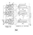
- FIG. 1 is a system diagram illustrating a high voltage, fast rise/fall time, high repetition rate pulse generator 10 according to one embodiment of the invention.
- high speed means pulses having a fast rise time and a fast fall time.
- Pulse generator 10 comprises a plurality of Blumlein pulse forming lines 12. Each Blumlein pulse forming line 12 is driven via a switching/pulse charging circuit 14 comprising a high voltage solid state switch 16 such as, for example, a high voltage switching MOSFET to form a pulse forming module 30.
- Pulse generator 10 can be seen to comprise a plurality of such pulse forming modules 30. These pulse forming modules 30 are substantially identical to one another according to one embodiment of the invention.
- Pulse generator 10 also comprises a transmission line transformer 40 that is configured within pulse generator 10 to multiply input voltage pulses generated via the plurality of Blumlein pulse forming lines 12 into high voltage pulses without degradation of pulse rise and fall times. Because the Blumlein pulse forming lines 12 are driven by solid state switches 16, pulse generator 10 advantageously generates high voltage, high speed pulses at a much higher repetition rate and with higher pulse rise and falls times and higher pulse voltage magnitudes than can be achieved when using conventional gap switch pulse generators commonly employed in the prior art. One workable embodiment was found to achieve a pulse repetition rate exceeding 100kpps, a pulse rise/fall time of about 10 nanoseconds, a high voltage magnitude of at least 30 kV, and a pulse width of about 20 nanoseconds.
- solid state based switches 16 further advantageously allows pulse generator 10 to be constructed in a manner that is substantially smaller, substantially more efficient, and substantially more reliable than conventional gap switch pulse generators commonly employed in the prior art.
- each switching/pulse charging circuit 14 further comprises a diode 18 and an inductor 20.
- a switching operation of each switch 16 causes each corresponding inductor 20 to develop a differential pulse voltage and also provides high frequency isolation between switch 16 ground connections and the inner conductor 22 and outer shield 24 of each corresponding Blumlein pulse forming line 12 as a DC voltage source 26 is switched on and off.
- each Blumlein pulse forming line comprises distributed capacitance characteristics, a differential voltage having a magnitude approximately twice the DC input voltage 26 level is stored across this Blumlein pulse forming line distributed capacitance during each switching cycle.
- Diode 18 operates to prevent undesired backcharging of the pulse voltage during the switching cycle, allowing creation of the desired pulse voltage signal.
- Each line of the transmission line transformer 40 and each of the Blumlein pulse forming lines 12 are constructed of the same type of coaxial cable according to one embodiment of the invention.
- the transmission line transformer 40 is configured generate a high voltage, high speed, high repetition rate voltage pulse having a magnitude equivalent to the total number N of pulse forming modules 30 times the magnitude of a voltage pulse generated via a single pulse forming module 30.
- the high voltage, high speed, high repetition rate pulse generator 10 offers several advantages over the conventional gap switch pulse generators that are known in the art. Some of these advantages include 1) the use of modular design providing ease of manufacture and high reliability, 2) substantially perfect matching between the Blumlein pulse forming line and its corresponding transmission line transformer for high efficiency, 3) the capability of using different length lines to construct the transmission line transformer, 4) propagation time delays that can be easily compensated by switch gate signals, 5) configuration of switches that each drive a pair of lines forming a floating transmission line, 6) switch ground connections that are isolated with chokes/inductors, 7) a high efficiency topology in which very minimal energy is wasted within the structure of the transmission line transformer itself, 8) superior current sharing features, 9) switching speeds determined only by transmission line and solid-state switch characteristics, 10) compact topology requiring minimal real-estate, 11) a voltage pulse amplitude that is proportional to an input voltage amplitude, and 12) a pulse repetition rate that is limited only by magnetic material and charging circuit characteristics.
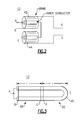
- Figures 2 and 3 together illustrate construction of a Blumlein pulse forming line 12 according to one embodiment of the invention.
- Figure 2 depicts a single Blumlein pulse forming line 12 as also depicted in each pulse forming module 30 of Figure 1 .
- Blumlein pulse forming line 12 is represented in Figure 2 as a pair of coaxial transmission line elements 42, 44, each having an inner conductor 22 and an outer shield 24 encapsulating the inner conductor 22 along the entire length of the corresponding coaxial line 42, 44.
- a signal input end of coaxial line 42 is represented as 'A', while a corresponding open circuit end of coaxial line 44 is represented as 'E'.
- Inner conductor 22 of coaxial line 42 is shorted to inner conductor 22 of coaxial line 44.
- the shield 24 of coaxial line 42 is represented as 'B" at the signal input end of coaxial line 42.
- the outer shield 24 of coaxial line 42 is represented as signal output node 'C' at the end opposite the signal input end 'A' of coaxial line 42; while the outer shield 24 of coaxial line 44 is represented as signal output node 'D' at the end opposite the open circuit end 'E' of coaxial line 44.
- FIG 3 is a diagram illustrating the physical construction of a Blumlein pulse forming line 12 suitable for use in the pulse generator 10 depicted in Figure 1 , according to one embodiment of the invention.
- Blumlein pulse forming line 12 comprises a single length of coaxial type transmission cable 46 that is formed into a U-shape transmission element.
- the single inner conductor 22 is shorted together at its exposed ends represented as 'A' which corresponds to the shorted inner conductors depicted in Figure 2 .
- the outer shield 24 of the U-shape transmission element is separated at the center, along the straight portions of the U-shape transmission element such that the U-shape transmission element is characterized by two subelements 48, 50.
- the first transmission sub-element 48 comprises the two straight portions, each having a length 'L', and having the outer shield of each portion shorted together at the point of separation, as depicted in Figure 3 .
- the second transmission sub-element 50 comprises the remaining U-shape portion, having its outer shield shorted together at the point of separation, as also depicted in Figure 3 .
- This physical Blumlein pulse forming line 12 then has one input 'A' that corresponds with the conductor 22 input 'A' depicted in Figures 2 and 3 , and another input 'B' that corresponds with the outer shield 24 input 'B' depicted in Figures 1 and 2 .
- the first transmission sub-element 48 has a first output 'C' at the point where the outer shields are shorted together, corresponding with output 'C' in Figure 2 .
- the second transmission sub-element 50 has a second output 'D' at the point where the ends of the outer shield are shorted together, corresponding with output 'D' in Figure 2 .
- the U-shape portion 'E' of transmission sub-element 50 corresponds with the open circuit end 'E' in Figure 2 .
- Blumlein pulse forming line 12 advantageously provides excellent impedance matching characteristics when it comprises the same type of transmission lines, i.e. coaxial cable, as the transmission line transformer 40.
- the physical construction of a Blumlein pulse forming line 12 described above with reference to Figure 3 also advantageously has a minimal number of high voltage joints, a feature that reduces occurrences of undesirable corona discharge.
- Figure 4 is a diagram illustrating the physical construction of a transmission line transformer 40 that advantageously functions in a manner that substantially eliminates undesired parasitic/secondary or common mode propagation errors according to one embodiment of the invention.
- the left portion of Figure 4 depicts an axial view of the transmission line transformer 40, while the right portion of Figure 4 depicts a perspective view of the transmission line transformer 40.
- Transmission line transformer 40 includes a high-mu magnetic core 60 according to one embodiment.
- Each individual transformer 40 transmission line L1-Ln is wound around the magnetic core 60 to form a torroid 62 in accordance with a suitable construction rule.
- Line L1 for example, can pass straight through the magnetic core 60 without being wound around the core 60.
- Line L2 for example, can be wound around the magnetic core 60 once to form a single turn of the torroid 52.
- Line L3, for example, can be wound around the magnetic core 60 twice to form two turns of the torroid 62, and so on.
- Table 1 below illustrates a winding rule according to one embodiment that was found suitable by the present inventors to provide desired working results.
- Table 1 - Torroid Winding Rule Turns ⁇ L1 0 0 L2 1*m, where m is an integer 4*180°/[m(n-1)], where n is an integer ... .... ⁇ Lj, where j is an integer (j-1)*m 4*180°(j-1)/[m(n-1)] ... ... ⁇ Ln n*m 4*180°/n ⁇ n(n-1)m/2 360°
- each of the lines L1-Ln are separated to minimize parasitic coupling while the tails are in close proximity to allow easy interconnection according to one embodiment.
- the length of each of the lines L1-Ln are kept as small as practical to minimize line losses.
- each of the lines L1-Ln are tightly wound on a high-mu core 60 such that each loop is guaranteed to have substantially the same voltage drop.
- a significant advantage provided by the pulse generator 10 using the foregoing torroidal construction techniques is the capability to calibrate gate drive signals to the solid-state switches 16 in a manner that ensures that every pulse generated by the pulse generator 10 arrives at the output/load at substantially the same point in time.
- Another significant advantage provided by the foregoing torroidal construction techniques is the increased capability to preserve the integrity of the pulses generated by the pulse generator 10.
Landscapes
- Generation Of Surge Voltage And Current (AREA)
- Amplifiers (AREA)
Abstract
Description
- The invention relates generally to electronic power conversion and more particularly to a solid state high voltage, fast rise/fall time, and high pulse repetition rate pulse generator using a transmission line transformer.
- Plasma generators capable of operating at high voltages with fast pulse rise and fall times, and high pulse repetition rates have generally employed radio frequency (RF) power amplifiers and related technology to accomplish high voltage, high speed and high pulse repetition rate generation and transmission. Such RF power amplifiers are expensive to produce and suffer in reliability due to internal heat build-up during high pulse repetition rate generation. RF amplifiers also undesirably require significant real estate and generally have low electric efficiency. Further, RF power amplifier technology is not particularly suitable for generation of high pulse repetition rates due to thermal losses, among other things.
- Known high voltage pulse generators for the generation of plasma and the like generally employ gap type switches that substantially limit the upper pulse repetition rate as well as the overall system reliability level. These known high voltage pulse generation systems also require a substantial amount of real estate to provide a working system due to structural limitations.
- It would be both advantageous and beneficial to provide a high voltage, fast rise/fall time, high pulse repetition rate pulse generator that overcomes the high pulse repetition rate limitations associated with conventional high voltage pulse generators. It would be further advantageous if the high voltage, fast rise/fall time, high pulse repetition rate pulse generator were capable of continued operation without impairment of the pulse generator during substantially longer time periods than that achievable using conventional high voltage pulse generators. It would be further advantageous if the high voltage, fast rise/fall time, high pulse repetition rate pulse generator occupied substantially less real estate to provide a working system than that required by conventional high voltage pulse generators.
- Briefly, in accordance with one embodiment of the present invention, a pulse generator for generating high voltage, fast rise/fall time, high repetition rate pulses comprises: a plurality of pulse forming modules, each module comprising a solid-state switch; and a transmission line transformer configured to generate high voltage, fast rise/fall time, high repetition rate pulses in response to voltage pulses generated via the plurality of pulse forming modules.
- According to another embodiment, a system for generating high voltage, fast rise/fall time, high repetition rate pulses comprises: a plurality of solid-state switches; a pulse forming line corresponding to each solid-state switch, each pulse forming line configured to generate a high fast rise/fall time, high repetition rate voltage pulse simultaneously with each other in response to operation of its corresponding solid-state switch; and a transmission line transformer configured to generate high voltage, fast rise/fall time, high repetition rate pulses in response to the voltage pulses generated via the pulse forming lines.
- According to yet another embodiment, a plasma pulse generation system comprises: a plurality of solid-state switching pulse forming modules; and a transmission line transformer configured to generate high voltage, fast rise/fall time, high repetition rate output pulses for the generation of plasma in response to input voltage pulses generated via the plurality of pulse forming modules.
- Various features, aspects, and advantages of the present invention will become better understood when the following detailed description is read with reference to the accompanying drawings in which like characters represent like parts throughout the drawings, wherein:
-
Figure 1 is a system diagram illustrating a high voltage, fast rise/fall time, high repetition rate pulse generator according to one embodiment of the invention; -
Figure 2 illustrates one of the Blumlein pulse forming lines depicted inFigure 1 modified with alphabetical characters representing different parts of the Blumlein pulse forming line; -
Figure 3 is a diagram illustrating construction of a Blumlein pulse forming line according to one embodiment of the invention; and -
Figure 4 is a diagram illustrating construction of a transmission line transformer according to one embodiment of the invention. - While the above-identified drawing figures set forth alternative embodiments, other embodiments of the present invention are also contemplated, as noted in the discussion. In all cases, this disclosure presents illustrated embodiments of the present invention by way of representation and not limitation. Numerous other modifications and embodiments can be devised by those skilled in the art which fall within the scope and spirit of the principles of this invention.
-
Figure 1 is a system diagram illustrating a high voltage, fast rise/fall time, high repetitionrate pulse generator 10 according to one embodiment of the invention. As used herein, high speed means pulses having a fast rise time and a fast fall time.Pulse generator 10 comprises a plurality of Blumleinpulse forming lines 12. Each Blumleinpulse forming line 12 is driven via a switching/pulse charging circuit 14 comprising a high voltagesolid state switch 16 such as, for example, a high voltage switching MOSFET to form a pulse forming module 30.Pulse generator 10 can be seen to comprise a plurality of such pulse forming modules 30. These pulse forming modules 30 are substantially identical to one another according to one embodiment of the invention. -
Pulse generator 10 also comprises atransmission line transformer 40 that is configured withinpulse generator 10 to multiply input voltage pulses generated via the plurality of Blumleinpulse forming lines 12 into high voltage pulses without degradation of pulse rise and fall times. Because the Blumleinpulse forming lines 12 are driven bysolid state switches 16,pulse generator 10 advantageously generates high voltage, high speed pulses at a much higher repetition rate and with higher pulse rise and falls times and higher pulse voltage magnitudes than can be achieved when using conventional gap switch pulse generators commonly employed in the prior art. One workable embodiment was found to achieve a pulse repetition rate exceeding 100kpps, a pulse rise/fall time of about 10 nanoseconds, a high voltage magnitude of at least 30 kV, and a pulse width of about 20 nanoseconds. - The use of solid state based
switches 16 further advantageously allowspulse generator 10 to be constructed in a manner that is substantially smaller, substantially more efficient, and substantially more reliable than conventional gap switch pulse generators commonly employed in the prior art. - With continued reference to
Figure 1 , each switching/pulse charging circuit 14 further comprises adiode 18 and aninductor 20. A switching operation of eachswitch 16 causes eachcorresponding inductor 20 to develop a differential pulse voltage and also provides high frequency isolation betweenswitch 16 ground connections and theinner conductor 22 andouter shield 24 of each corresponding Blumleinpulse forming line 12 as aDC voltage source 26 is switched on and off. Because each Blumlein pulse forming line comprises distributed capacitance characteristics, a differential voltage having a magnitude approximately twice theDC input voltage 26 level is stored across this Blumlein pulse forming line distributed capacitance during each switching cycle.Diode 18 operates to prevent undesired backcharging of the pulse voltage during the switching cycle, allowing creation of the desired pulse voltage signal. - Each line of the
transmission line transformer 40 and each of the Blumleinpulse forming lines 12 are constructed of the same type of coaxial cable according to one embodiment of the invention. Thetransmission line transformer 40, according to one embodiment, is configured generate a high voltage, high speed, high repetition rate voltage pulse having a magnitude equivalent to the total number N of pulse forming modules 30 times the magnitude of a voltage pulse generated via a single pulse forming module 30. - The high voltage, high speed, high repetition
rate pulse generator 10 offers several advantages over the conventional gap switch pulse generators that are known in the art. Some of these advantages include 1) the use of modular design providing ease of manufacture and high reliability, 2) substantially perfect matching between the Blumlein pulse forming line and its corresponding transmission line transformer for high efficiency, 3) the capability of using different length lines to construct the transmission line transformer, 4) propagation time delays that can be easily compensated by switch gate signals, 5) configuration of switches that each drive a pair of lines forming a floating transmission line, 6) switch ground connections that are isolated with chokes/inductors, 7) a high efficiency topology in which very minimal energy is wasted within the structure of the transmission line transformer itself, 8) superior current sharing features, 9) switching speeds determined only by transmission line and solid-state switch characteristics, 10) compact topology requiring minimal real-estate, 11) a voltage pulse amplitude that is proportional to an input voltage amplitude, and 12) a pulse repetition rate that is limited only by magnetic material and charging circuit characteristics. -
Figures 2 and 3 together illustrate construction of a Blumleinpulse forming line 12 according to one embodiment of the invention.Figure 2 depicts a single Blumleinpulse forming line 12 as also depicted in each pulse forming module 30 ofFigure 1 . Blumleinpulse forming line 12 is represented inFigure 2 as a pair of coaxialtransmission line elements inner conductor 22 and anouter shield 24 encapsulating theinner conductor 22 along the entire length of the correspondingcoaxial line coaxial line 42 is represented as 'A', while a corresponding open circuit end ofcoaxial line 44 is represented as 'E'.Inner conductor 22 ofcoaxial line 42 is shorted toinner conductor 22 ofcoaxial line 44. Theshield 24 ofcoaxial line 42 is represented as 'B" at the signal input end ofcoaxial line 42. Theouter shield 24 ofcoaxial line 42 is represented as signal output node 'C' at the end opposite the signal input end 'A' ofcoaxial line 42; while theouter shield 24 ofcoaxial line 44 is represented as signal output node 'D' at the end opposite the open circuit end 'E' ofcoaxial line 44. -
Figure 3 is a diagram illustrating the physical construction of a Blumleinpulse forming line 12 suitable for use in thepulse generator 10 depicted inFigure 1 , according to one embodiment of the invention. Blumleinpulse forming line 12 comprises a single length of coaxialtype transmission cable 46 that is formed into a U-shape transmission element. The singleinner conductor 22 is shorted together at its exposed ends represented as 'A' which corresponds to the shorted inner conductors depicted inFigure 2 . Theouter shield 24 of the U-shape transmission element is separated at the center, along the straight portions of the U-shape transmission element such that the U-shape transmission element is characterized by twosubelements first transmission sub-element 48 comprises the two straight portions, each having a length 'L', and having the outer shield of each portion shorted together at the point of separation, as depicted inFigure 3 . Thesecond transmission sub-element 50 comprises the remaining U-shape portion, having its outer shield shorted together at the point of separation, as also depicted inFigure 3 . This physical Blumleinpulse forming line 12 then has one input 'A' that corresponds with theconductor 22 input 'A' depicted inFigures 2 and 3 , and another input 'B' that corresponds with theouter shield 24 input 'B' depicted inFigures 1 and2 . Thefirst transmission sub-element 48 has a first output 'C' at the point where the outer shields are shorted together, corresponding with output 'C' inFigure 2 . Thesecond transmission sub-element 50 has a second output 'D' at the point where the ends of the outer shield are shorted together, corresponding with output 'D' inFigure 2 . The U-shape portion 'E' oftransmission sub-element 50 corresponds with the open circuit end 'E' inFigure 2 . - Blumlein
pulse forming line 12 advantageously provides excellent impedance matching characteristics when it comprises the same type of transmission lines, i.e. coaxial cable, as thetransmission line transformer 40. The physical construction of a Blumleinpulse forming line 12 described above with reference toFigure 3 also advantageously has a minimal number of high voltage joints, a feature that reduces occurrences of undesirable corona discharge. -
Figure 4 is a diagram illustrating the physical construction of atransmission line transformer 40 that advantageously functions in a manner that substantially eliminates undesired parasitic/secondary or common mode propagation errors according to one embodiment of the invention. The left portion ofFigure 4 depicts an axial view of thetransmission line transformer 40, while the right portion ofFigure 4 depicts a perspective view of thetransmission line transformer 40.Transmission line transformer 40 includes a high-mumagnetic core 60 according to one embodiment. - Each individual transformer 40 transmission line L1-Ln is wound around the
magnetic core 60 to form atorroid 62 in accordance with a suitable construction rule. Line L1, for example, can pass straight through themagnetic core 60 without being wound around thecore 60. Line L2, for example, can be wound around themagnetic core 60 once to form a single turn of the torroid 52. Line L3, for example, can be wound around themagnetic core 60 twice to form two turns of thetorroid 62, and so on. Table 1 below illustrates a winding rule according to one embodiment that was found suitable by the present inventors to provide desired working results.Table 1 - Torroid Winding Rule Turns Θ L1 0 0 L2 1*m, where
m is an integer4*180°/[m(n-1)], where
n is an integer... .... ··· Lj, where
j is an integer(j-1)*m 4*180°(j-1)/[m(n-1)] ... ... ··· Ln n*m 4*180°/n Σ n(n-1)m/2 360° - The inputs of the lines L1-Ln are separated to minimize parasitic coupling while the tails are in close proximity to allow easy interconnection according to one embodiment. According to one aspect of the invention, the length of each of the lines L1-Ln are kept as small as practical to minimize line losses. According to another aspect of the invention, each of the lines L1-Ln are tightly wound on a high-
mu core 60 such that each loop is guaranteed to have substantially the same voltage drop. - A significant advantage provided by the
pulse generator 10 using the foregoing torroidal construction techniques is the capability to calibrate gate drive signals to the solid-state switches 16 in a manner that ensures that every pulse generated by thepulse generator 10 arrives at the output/load at substantially the same point in time. Another significant advantage provided by the foregoing torroidal construction techniques is the increased capability to preserve the integrity of the pulses generated by thepulse generator 10. - While only certain features of the invention have been illustrated and described herein, many modifications and changes will occur to those skilled in the art. It is, therefore, to be understood that the appended claims are intended to cover all such modifications and changes as fall within the true spirit of the invention.
- Various aspects and embodiment of the present invention are now defined by the following numbered clauses:
- 1. A pulse generator comprising:
- a plurality of pulse forming modules, each module comprising a solid-state switch; and
- a transmission line transformer configured together with the plurality of pulse forming modules to generate high voltage, fast rise/fall time, high repetition rate pulses in response to voltage pulses generated via the plurality of pulse forming modules.
- 2. The pulse generator according to
clause 1, wherein each pulse forming module comprises a coaxial transmission cable configured as a Blumlein pulse forming line. - 3. The pulse generator according to any preceding clause, wherein the coaxial transmission cable is configured in a U-shape with its outer shield split into two sections, and further wherein the coaxial transmission cable has its inner conductor and its outer shield sections connected to create an equivalent coaxial cable transmission pair in a parallel arrangement.
- 4. The pulse generator according to any preceding clause, wherein each pulse forming module further comprises:
- a diode; and
- an inductor configured in combination with the diode and the solid-state switch to generate a differential voltage pulse having a magnitude approximately twice the magnitude of a DC input voltage, the inductor further configured to provide isolation between the solid-state switch and a DC voltage source ground.
- 5. The pulse generator according to any preceding clause, wherein the transmission line transformer comprises a plurality of coaxial transmission cables configured together to generate the high voltage, fast rise/fall time, high repetition rate voltage pulses.
- 6. The pulse generator according to any preceding clause, wherein the transmission line transformer coaxial transmission cables are configured together with a high-mu magnetic core as a torroid.
- 7. The pulse generator according to any preceding clause, wherein the plurality of solid-state switches are configured to switch at different points in time such that a high voltage, fast rise/fall time, high repetition rate voltage pulse generated via each transmission line transformer coaxial transmission cable arrives at a pulse generator output at substantially the same point in time.
- 8. The pulse generator according to any preceding clause, wherein the inputs of the plurality of transmission line transformer coaxial transmission cables are separated to minimize parasitic coupling while the tails of the plurality of transmission line transformer coaxial transmission cables are in close proximity to allow easy interconnection.
- 9. The pulse generator according to any preceding clause, wherein the transmission line transformer together with the plurality of pulse forming modules is configured to generate high voltage, fast rise/fall time pulses at a pulse rate ranging from about 1 pulse-per-second to at least 100 kilo pulses-per-second at a voltage level up to about 30 kV.
- 10. A pulse generating system comprising:
- a plurality of solid-state switches;
- a pulse forming line corresponding to each solid-state switch, each pulse forming line configured to generate a fast rise/fall time, high repetition rate voltage pulse in response to operation of its corresponding solid-state switch; and
- a transmission line transformer configured to generate high voltage, fast rise/fall time, high repetition rate pulses in response to combined voltage pulses generated via the pulse forming lines.
- 11. The pulse generating system according to
clause 10, wherein each pulse forming line in combination with its corresponding solid-state switch is configured as a pulse forming module. - 12. The pulse generating system according to
clause 10 or 11, wherein each pulse forming module further comprises:- a diode; and
- an inductor configured in combination with the diode and its corresponding solid-state switch to generate a differential voltage pulse having a magnitude approximately twice the magnitude of a DC input voltage, the inductor further configured to provide isolation between the corresponding solid-state switch and a DC voltage source ground.
- 13. The pulse generating system according to any of
clauses 10 to 12, wherein each pulse forming line is configured as a Blumlein pulse forming line. - 14. The pulse generating system according to any of
clauses 10 to 13, wherein the coaxial transmission cables are configured together with a high-mu magnetic core as a torroid. - 15. The pulse generating system according to any of
clauses 10 to 14, wherein the high voltage, fast rise/fall time, high repetition rate pulses have a maximum voltage magnitude of about 30 kV at a desired pulse repetition rate from about 1 pulse-per-second (pps) to about 100 kpps . - 16. The pulse generating system according to any of
clauses 10 to 15, wherein the plurality of solid-state switches are configured to switch at different points in time such that the high voltage, fast rise/fall time, high repetition rate pulses generated via the transmission line transformer are generated in unison. - 17. A plasma pulse generation system comprising:
- a plurality of solid-state switching pulse forming modules; and
- a transmission line transformer configured to generate high voltage, fast rise/fall time, high repetition rate output pulses having sufficient pulse characteristics for the generation of plasma in response to input voltage pulses generated via the plurality of pulse forming modules.
- 18. The plasma pulse generation system according to clause 17, wherein each pulse forming module comprises a coaxial transmission cable configured as a Blumlein pulse forming line.
- 19. The plasma pulse generation system according to
clause 17 or 18, wherein each coaxial transmission cable is configured in a U-shape with its outer shield split into two sections, and further wherein the coaxial transmission cable has its inner conductor and its outer shield sections connected to create an equivalent coaxial cable transmission pair in a parallel arrangement. - 20. The plasma pulse generation system according to any of clauses 17 to 19, wherein each pulse forming module further comprises a solid-state switch configured to drive its corresponding pulse forming line such that the high voltage, fast rise/fall time, high repetition rate output pulses are generated in unison.
- 21. The plasma pulse generation system according to any of clauses 17 to 20, wherein each pulse forming module further comprises:
- a diode; and
- an inductor configured in combination with the diode and its corresponding solid-state switch to generate a differential voltage pulse having a magnitude approximately twice the magnitude of a DC input voltage, the inductor further configured to provide isolation between the corresponding solid-state switch and a DC voltage source ground.
- 22. The plasma pulse generation system according to any of clauses 17 to 21, wherein the transmission line transformer comprises a plurality of coaxial transmission cables configured together with a high-mu magnetic core as a torroid.
- 23. The plasma pulse generation system according to any of clauses 17 to 22, wherein the plurality of coaxial transmission cables comprise inputs separated to minimize parasitic coupling and tails in close proximity to allow easy interconnection.
- 24. The plasma pulse generation system according to any of clauses 17 to 23, wherein the plurality of solid-state switching pulse forming modules are configured to switch at different points in time such that the input voltage pulse generated via each pulse forming module arrives at the transmission line transformer at a different point in time.
- 25. The plasma pulse generation system according to any of clauses 17 to 24, wherein the transmission line transformer together with the plurality of pulse forming modules is configured to generate high voltage, fast rise/fall time, high repetition rate pulses at a pulse rate ranging from about 1 pulse-per-second to at least 100 kilo pulses-per-second at a voltage level up to about 30 kV.
Claims (10)
- A pulse generator (10) comprising:a plurality of pulse forming modules (30), each module comprising a solid-state switch (16); anda transmission line transformer (40) configured together with the plurality of pulse forming modules (30) to generate high voltage, fast rise/fall time, high repetition rate pulses in response to voltage pulses generated via the plurality of pulse forming modules.
- The pulse generator (10) according to claim 1, wherein each pulse forming module (30) comprises a coaxial transmission cable (46) configured as a Blumlein pulse forming line.
- The pulse generator (10) according to claim 2, wherein the coaxial transmission cable (46) is configured in a U-shape with its outer shield (24) split into two sections, and further wherein the coaxial transmission cable has its inner conductor (22) and its outer shield sections connected to create an equivalent coaxial cable transmission pair in a parallel arrangement.
- The pulse generator (10) according to any preceding claim, wherein each pulse forming module (30) further comprises:a diode (18); andan inductor (20) configured in combination with the diode (18) and the solid-state switch (16) to generate a differential voltage pulse having a magnitude approximately twice the magnitude of a DC input voltage, the inductor further configured to provide isolation between the solid-state switch and a DC voltage source ground.
- The pulse generator (10) according to any preceding claim, wherein the transmission line transformer (40) comprises a plurality of coaxial transmission cables configured together to generate the high voltage, fast rise/fall time, high repetition rate voltage pulses.
- The pulse generator (10) according to claim 5, wherein the transmission line transformer coaxial transmission cables are configured together with a high-mu magnetic core as a torroid (62).
- The pulse generator (10) according to claim 5 or claim 6, wherein the plurality of solid-state switches (16) are configured to switch at different points in time such that a high voltage, fast rise/fall time, high repetition rate voltage pulse generated via each transmission line transformer coaxial transmission cable arrives at a pulse generator output at substantially the same point in time.
- The pulse generator (10) according to any of claims 5 to 7, wherein the inputs of the plurality of transmission line transformer coaxial transmission cables are separated to minimize parasitic coupling while the tails of the plurality of transmission line transformer coaxial transmission cables are in close proximity to allow easy interconnection.
- The pulse generator (10) according to any preceding claim, wherein the transmission line transformer (40) together with the plurality of pulse forming modules (30) is configured to generate high voltage, fast rise/fall time pulses at a pulse rate ranging from about 1 pulse-per-second to at least 100 kilo pulses-per-second at a voltage level up to about 30 kV.
- A plasma pulse generation system (10) comprising:a plurality of solid-state switching pulse forming modules (30); anda transmission line transformer (40) configured to generate high voltage, fast rise/fall time, high repetition rate output pulses having sufficient pulse characteristics for the generation of plasma in response to input voltage pulses generated via the plurality of pulse forming modules (30).
Applications Claiming Priority (1)
| Application Number | Priority Date | Filing Date | Title |
|---|---|---|---|
| US12/074,447 US7884504B2 (en) | 2008-03-03 | 2008-03-03 | Transmission line based high voltage pulse generator |
Publications (2)
| Publication Number | Publication Date |
|---|---|
| EP2099131A2 true EP2099131A2 (en) | 2009-09-09 |
| EP2099131A3 EP2099131A3 (en) | 2013-07-10 |
Family
ID=40823157
Family Applications (1)
| Application Number | Title | Priority Date | Filing Date |
|---|---|---|---|
| EP09250521.3A Withdrawn EP2099131A3 (en) | 2008-03-03 | 2009-02-26 | Transmission line based high voltage pulse generator |
Country Status (2)
| Country | Link |
|---|---|
| US (1) | US7884504B2 (en) |
| EP (1) | EP2099131A3 (en) |
Cited By (1)
| Publication number | Priority date | Publication date | Assignee | Title |
|---|---|---|---|---|
| WO2013109424A3 (en) * | 2012-01-17 | 2013-09-19 | Compact Particle Acceleration Corporation | High voltage rf opto-electric multiplier for charged particle accelerators |
Families Citing this family (13)
| Publication number | Priority date | Publication date | Assignee | Title |
|---|---|---|---|---|
| US7633182B2 (en) * | 2005-11-09 | 2009-12-15 | Bae Systems Advanced Technologies, Inc. | Bipolar pulse generators with voltage multiplication |
| US8004120B2 (en) | 2009-03-13 | 2011-08-23 | Bae Systems Information And Electronic Systems Integration Inc. | High power bipolar pulse generators |
| US8649188B2 (en) | 2011-10-31 | 2014-02-11 | General Electric Company | Solid state pulsed power generator |
| CN105207651B (en) * | 2015-09-18 | 2017-12-15 | 西北核技术研究所 | The coaxial pulse of high impedance high voltage output forms line |
| CN105577151B (en) * | 2016-03-07 | 2018-05-25 | 中国工程物理研究院应用电子学研究所 | A kind of squarer |
| US10224895B2 (en) * | 2017-01-03 | 2019-03-05 | Raytheon Company | Transmission line transformers |
| CN106953620B (en) * | 2017-03-23 | 2021-02-12 | 西北核技术研究所 | Tandem high repetition frequency pulse generating device |
| CN106941346B (en) * | 2017-04-20 | 2019-09-24 | 重庆大学 | Modular solid-state millimicrosecond pulse generator based on PCBBlumlein transmission line and PCB line transformer |
| CN107040226B (en) * | 2017-06-08 | 2021-02-19 | 钢研纳克检测技术股份有限公司 | Fully-differential-driven radio frequency generator |
| CN108540007A (en) * | 2018-04-09 | 2018-09-14 | 重庆大学 | A kind of adjustable modularization Gao Zhongying millimicrosecond pulse generator of polarity |
| US11302518B2 (en) * | 2018-07-27 | 2022-04-12 | Eagle Harbor Technologies, Inc. | Efficient energy recovery in a nanosecond pulser circuit |
| KR20220054843A (en) * | 2019-10-01 | 2022-05-03 | 펄스 바이오사이언스, 인크. | Apparatus and method for limiting load current in nanosecond pulsed power supply |
| US12074594B2 (en) | 2022-05-03 | 2024-08-27 | Rockwell Coll ins, Inc. | Generation and shaping of electromagnetic pulses using time-varying transmission lines |
Family Cites Families (5)
| Publication number | Priority date | Publication date | Assignee | Title |
|---|---|---|---|---|
| US4536723A (en) * | 1983-11-25 | 1985-08-20 | Sanders Associates, Inc. | High-power pulse generator using transmission line with spark discharge device |
| US5138270A (en) * | 1988-11-24 | 1992-08-11 | Shuhei Nakata | High voltage pulse generator |
| US6066901A (en) * | 1998-09-17 | 2000-05-23 | First Point Scientific, Inc. | Modulator for generating high voltage pulses |
| US6756874B2 (en) * | 2000-03-21 | 2004-06-29 | Bechtel Nevada Corporation | Series transmission line transformer |
| NL1019171C2 (en) * | 2001-10-15 | 2003-04-18 | Univ Eindhoven Tech | High voltage pulse generator comprises at least one resonant charging connection, capacitor-spark bridge combination and transmission line transformer |
-
2008
- 2008-03-03 US US12/074,447 patent/US7884504B2/en not_active Expired - Fee Related
-
2009
- 2009-02-26 EP EP09250521.3A patent/EP2099131A3/en not_active Withdrawn
Cited By (2)
| Publication number | Priority date | Publication date | Assignee | Title |
|---|---|---|---|---|
| WO2013109424A3 (en) * | 2012-01-17 | 2013-09-19 | Compact Particle Acceleration Corporation | High voltage rf opto-electric multiplier for charged particle accelerators |
| US8598813B2 (en) | 2012-01-17 | 2013-12-03 | Compact Particle Acceleration Corporation | High voltage RF opto-electric multiplier for charge particle accelerations |
Also Published As
| Publication number | Publication date |
|---|---|
| US20090219071A1 (en) | 2009-09-03 |
| US7884504B2 (en) | 2011-02-08 |
| EP2099131A3 (en) | 2013-07-10 |
Similar Documents
| Publication | Publication Date | Title |
|---|---|---|
| US7884504B2 (en) | Transmission line based high voltage pulse generator | |
| CN108923641B (en) | DSRD-based high-voltage fast pulse power supply | |
| US8232682B2 (en) | High power bipolar pulse generators | |
| US7986196B2 (en) | Method and apparatus for digital synthesis of long multi-cycle microwave pulses | |
| WO2016011972A1 (en) | Pulse power device based on annular ceramic solid state line | |
| Hao et al. | Development of a 90-stage inner-isolated all solid-state stacked Blumlein pulse generator | |
| US7583159B2 (en) | High power bipolar pulse generators with impedance transformation | |
| KR20160003010A (en) | Inductive isolation of voltage sources of an iva by means of individual coupled coils | |
| Tyo et al. | Differentially fed high-power microwave antennas using capacitively coupled hyperband inverters | |
| Heinemann et al. | Power supply for very high insulation requirements in IGBT gate-drives | |
| Qiu et al. | A pulsed power supply based on power semiconductor switches and transmission line transformer | |
| Cook et al. | Design and testing of a fast, 50 kV solid-state kicker pulser | |
| US7319281B2 (en) | Multi-stage Blumlein | |
| CN117595856A (en) | Analog multiplexer and electronic equipment | |
| Nunnally et al. | A compact 700-kV erected pulse forming network for HPM applications | |
| US8649188B2 (en) | Solid state pulsed power generator | |
| CN208241573U (en) | A kind of high pressure fast pulse power supply based on DSRD | |
| CN221531472U (en) | Analog multiplexer and electronic equipment | |
| KR102919392B1 (en) | Ultra-High Frequency Power Circuit with Multiple Connection Structure | |
| Rossi et al. | Design and Construction of a 150kV/300A/1us Blumlein Pulser | |
| Azad | Development of Pulsed Power Sources Using Self-Sustaining Nonlinear Transmission Lines and High-Voltage Solid-State Switches | |
| US6914350B2 (en) | Switching arrangement | |
| JP3246858B2 (en) | Power supply | |
| Krasnykh | Analysis of approaches for a design of APS-U fast injection system | |
| Zhou et al. | A Two-Level Stacked Blumlein Pulse Generator Using Bipolar-Charged Modules With Integrated High-Voltage Isolation |
Legal Events
| Date | Code | Title | Description |
|---|---|---|---|
| PUAI | Public reference made under article 153(3) epc to a published international application that has entered the european phase |
Free format text: ORIGINAL CODE: 0009012 |
|
| AK | Designated contracting states |
Kind code of ref document: A2 Designated state(s): AT BE BG CH CY CZ DE DK EE ES FI FR GB GR HR HU IE IS IT LI LT LU LV MC MK MT NL NO PL PT RO SE SI SK TR |
|
| AX | Request for extension of the european patent |
Extension state: AL BA RS |
|
| PUAL | Search report despatched |
Free format text: ORIGINAL CODE: 0009013 |
|
| AK | Designated contracting states |
Kind code of ref document: A3 Designated state(s): AT BE BG CH CY CZ DE DK EE ES FI FR GB GR HR HU IE IS IT LI LT LU LV MC MK MT NL NO PL PT RO SE SI SK TR |
|
| AX | Request for extension of the european patent |
Extension state: AL BA RS |
|
| RIC1 | Information provided on ipc code assigned before grant |
Ipc: H03K 3/57 20060101AFI20130603BHEP |
|
| AKY | No designation fees paid | ||
| REG | Reference to a national code |
Ref country code: DE Ref legal event code: R108 |
|
| REG | Reference to a national code |
Ref country code: DE Ref legal event code: R108 Effective date: 20140319 |
|
| STAA | Information on the status of an ep patent application or granted ep patent |
Free format text: STATUS: THE APPLICATION IS DEEMED TO BE WITHDRAWN |
|
| 18D | Application deemed to be withdrawn |
Effective date: 20140111 |