EP2099040A2 - Magnetic element - Google Patents
Magnetic element Download PDFInfo
- Publication number
- EP2099040A2 EP2099040A2 EP09006096A EP09006096A EP2099040A2 EP 2099040 A2 EP2099040 A2 EP 2099040A2 EP 09006096 A EP09006096 A EP 09006096A EP 09006096 A EP09006096 A EP 09006096A EP 2099040 A2 EP2099040 A2 EP 2099040A2
- Authority
- EP
- European Patent Office
- Prior art keywords
- core
- planar
- cores
- center
- magnetic
- Prior art date
- Legal status (The legal status is an assumption and is not a legal conclusion. Google has not performed a legal analysis and makes no representation as to the accuracy of the status listed.)
- Granted
Links
Images





Classifications
-
- H—ELECTRICITY
- H01—ELECTRIC ELEMENTS
- H01F—MAGNETS; INDUCTANCES; TRANSFORMERS; SELECTION OF MATERIALS FOR THEIR MAGNETIC PROPERTIES
- H01F17/00—Fixed inductances of the signal type
- H01F17/04—Fixed inductances of the signal type with magnetic core
- H01F17/045—Fixed inductances of the signal type with magnetic core with core of cylindric geometry and coil wound along its longitudinal axis, i.e. rod or drum core
-
- H—ELECTRICITY
- H01—ELECTRIC ELEMENTS
- H01F—MAGNETS; INDUCTANCES; TRANSFORMERS; SELECTION OF MATERIALS FOR THEIR MAGNETIC PROPERTIES
- H01F27/00—Details of transformers or inductances, in general
- H01F27/24—Magnetic cores
- H01F27/255—Magnetic cores made from particles
-
- H—ELECTRICITY
- H01—ELECTRIC ELEMENTS
- H01F—MAGNETS; INDUCTANCES; TRANSFORMERS; SELECTION OF MATERIALS FOR THEIR MAGNETIC PROPERTIES
- H01F3/00—Cores, Yokes, or armatures
- H01F3/10—Composite arrangements of magnetic circuits
- H01F3/12—Magnetic shunt paths
Definitions
- the present invention relates to a magnetic element.
- a configuration is disclosed in Japanese patent laid-open publication 2004-111754 in which a planar core is disposed in four directions consisting of both sides of the axial direction of the winding axis as well as both sides of the perpendicular direction to the winding axis so as to sandwich the coil wound around the columnar core, the directions perpendicular to the four directions in which the planar core described above is provided are opened, and the ends of the coil are drawn out from these opened locations.
- FIGS. 11A-11C show an exploded perspective view of a magnetic element 500 of the Japanese patent laid-open publication 2004-111754 .
- the magnetic element 500 comprises an upper first core 501, a lower second core 502, and two coils 503, 504.
- the first core 501 shown in FIG 11(A) , comprises a flat plane portion 501a; three planar side legs, 501b, 501b, and 501b, which project from a pair of opposed short ends as well as from the middle of the flat plane portion 501a; and columnar central legs 501d, 501d projecting from the centers of each of the recessed portions 501c, 501c, which are surrounded by the adjacent side legs 501b, 501b.
- four openings, 501e, 501e, 501e, 501e, are provided in a pair of opposed long ends along which no side leg 501b is provided.
- Each of the two coils 503, 504 shown in FIG 11(B) is an edgewise coil that is formed by winding rectangular wires coated with insulation.
- the insulation is peeled back from the beginnings and the ends of the windings of the coils 503, 504, and the ends solder plated and furthermore deformed into L-shaped forms so as to form ends 503a, 504a that are the terminals to be electrically connected.
- the second coil 502 shown in FIG. 11C has a rectangular, flat plane shape having short and long sides of lengths substantially identical to those of the short and long sides of the first core 501.
- the coils 503,504 fit into the recessed portions 501c, 501c of the first core 501, in a state in which the central legs 501d, 501d are inserted into center openings 503b, 504b. Then, in a state in which the coils 503, 504 are inserted into the recessed portions 501c, 501c of the first core 501, the second core 502 and the first core 501 are brought together, and the recessed portions 501 c, 501c are sealed by the second core 502.
- the flat plane portion 501a of the first core 501 and the second core 502 are disposed on both sides in the winding axis direction of the coils 503, 504.
- side legs 501b, 501b are disposed so as to sandwich the coil 503, and moreover, in directions perpendicular to the winding axis of coil 504, side legs 501b, 501b are disposed so as to sandwich the coil 504.
- a closed magnetic path is formed by the flat plane portion 501a of the first core 501, the second core 502, the side legs 501b and 501b.
- a closed magnetic path is formed by the flat plane portion 501a of the first core 501, the second core 502, the side legs 501b and 501b.
- the openings 501e and 501e are formed in the recessed portion 501c in which the coil 503 is holded.
- the openings 501e and 501e are formed in the recessed portion 501c in which the coil 504 is holded.
- the thicknesses of the side legs 501b, 501b, 501b are increased and their cross-sectional area is increased, then in order not to increase the mounting surface area of the magnetic element 500, it is necessary to increase the thicknesses of the side legs 501b, 501b, 501b toward the side of the coils 503, 504. When that is done, distance between the side legs 501b, 501b, 501b and the central legs 501d, 501d becomes narrower. As a result, the number of windings of the coils 503 and 504 is limited, and it is impossible to increase inductance value sufficiently.
- the present invention has as its object to provide a magnetic element the ends of the coil of which can be drawn out from the core easily, is compact, and further, is one in which magnetic saturation does not arise easily.
- the present invention has as its object to provide a magnetic element that relaxes restrictions on the number of windings in the coil and thereby enables a large inductance value to be obtained, or, alternatively, even if the number of windings is increased, relaxes restrictions on the thickness of the winding wire used so as to enable direct current resistance reduction.
- the present invention provides a magnetic element comprising a wound coil, a core body having a center core inserted into the inner periphery of the coil, planar cores disposed at both ends of the center core, and a side core disposed between the planar cores and on an outside periphery of the coil.
- the side core is disposed so as to form an open area between the two planar cores around the coil, with a recessed portion formed in a surface of the side core facing the coil in which the coil is partially contained.
- the side core and the center core form a single integrated unit with at least one of the two planar cores.
- Configuring the magnetic element as described above in addition to reducing the number of components, enables to reduce leakage magnetic flux because the side core and the center core form a single integrated unit with at least one of the two planar cores, and therefore these joint sections form a single integrated unit.
- a relation between a cross-sectional area S1 of the side core and a cross-sectional area S2 of the center core is such that S2 ⁇ S1 ⁇ 5 x S2.
- Configuring the magnetic element as described above enables to make it more difficult for magnetic saturation to occur.
- a relation between the cross-sectional area S2 of the center core and a cross-sectional area S3 of the planar core is such that S2 ⁇ S3 ⁇ 5 x S2.
- Configuring the magnetic element as described above enables to make it more difficult for magnetic saturation to occur.
- the side core is provided at a center of the planar core in a long direction of the planar core, and the center core is provided at two locations between the side core and both ends of the planar core in the long direction thereof.
- Configuring the magnetic element as described above enables one magnetic element to generate two magnetic fields.
- a relation between a cross-sectional area S4 of the side core and a cross-sectional area S5 of the center core is such that S5 + S5 ⁇ S4 ⁇ 5 x (S5 + S5).
- Configuring the magnetic element as described above enables to make it more difficult for magnetic saturation to occur.
- a relation between the cross-sectional area S5 of the center core and a cross-sectional area S6 of the planar core is such that S5 ⁇ S6 ⁇ 5 x S5.
- Configuring the magnetic element as described above enables to make it more difficult for magnetic saturation to occur.
- the side core is mounted at both ends of the planar core in the long direction thereof, and the center core is provided at two locations with a predetermined distance apart between the two side cores.
- Configuring the magnetic element as described above enables one magnetic element to generate two magnetic fields.
- a relation between a cross-sectional area S7 of the side core and a cross-sectional area S8 of the center core is such that S8 ⁇ S7 ⁇ 5 x S8.
- Configuring the magnetic element as described above enables to make it more difficult for magnetic saturation to occur.
- a relation between the cross-sectional area S8 of the center core and a cross-sectional area S9 of the planar core is such that S8 ⁇ S9 ⁇ 5 x S8.
- Configuring the magnetic element as described above enables to make it more difficult for magnetic saturation to occur.
- a side core is mounted at both ends of the planar core in a short direction thereof, and the center core is provided at two locations with a predetermined distance apart between the two side cores in parallel direction.
- Configuring the magnetic element as described above enables one magnetic element to generate two magnetic fields.
- a relation between a cross-sectional area S10 of the side core and a cross-sectional area S11 of the center core is such that S11 + S11 ⁇ S10 ⁇ 5 x (S11 + S11).
- Configuring the magnetic element as described above enables to make it more difficult for magnetic saturation to occur.
- a relation between a cross-sectional area S11 of the center core and a cross-sectional area S12 of the planar core is such that S11 ⁇ S12 ⁇ 5 x S11.
- Configuring the magnetic element as described above enables to make it more difficult for magnetic saturation to occur.
- an adhesive containing magnetic material is applied around the coil.
- the periphery of the coil is covered with an adhesive coating containing magnetic material, thus enabling leakage magnetic flux to be reduced.
- At least one of the center core, the planar core and the side core is formed from compressed metal powder. Configuring the magnetic element as described above enables the saturation magnetic flux density to be increased, thus further enabling the magnetic element to be made more compact.
- a magnetic element the ends of the coil of which can be drawn out from the core easily, is compact, and further, is one in which magnetic saturation does not arise easily, can be obtained.
- a magnetic element can be obtained that relaxes restrictions on the number of windings in the coil and thereby enables a large inductance value to be obtained, or, alternatively, relaxes restrictions on the thickness of the winding wire used so as to achieve direct current resistance reduction even if the number of windings is increased.
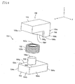
- FIG. 1 is a perspective view of a magnetic element according to the first embodiment of the present invention.
- FIG 2 is an exploded perspective view of the magnetic element shown in FIG 1 .
- An inductance element 100 as a magnetic element has a core unit 101 and a coil 102.
- the core unit 101 has planar cores 103, 104, a center core 105, and a side core 106.
- the planar cores 103, 104 are wholly thin, flat, rectangular solids in the long direction of the center core 105, and both have substantially identical shapes.
- a direction from a short side surface 104a to a short side surface 104b of the planar core 104 is referred to as the front (front side), the reverse direction thereof is referred to as the rear (rear side), a right-hand direction, looking from the rear toward the front, is referred to as right (right side), and a left-hand direction looking from the rear toward the front is referred to as left (left side).
- a direction in which the planar core 103 is disposed with respect to the planar core 104 is referred to as up (upper side) and the reverse direction thereof is referred to as down (lower side).
- the X-axis direction is front
- the Y-axis direction is left
- the Z-axis direction is up.
- the center core 105 is a cylindrical column, with its long direction in the vertical direction.
- the side core 106 is substantially saddle-shaped column in cross-section along a plane in the lateral and longitudinal directions of the planar core 104, in other words, along in the X-Y plane. That is, a rear side surface 106a, left and right lateral surfaces 106b, 106c, and a top end surface 106d of the side core 106 are all flat, with a recessed portion 106g curved in the shape of an inward-(rearward-) facing arc formed in a front side surface 106f. It should be noted that the side core 106 is columnar, and its shape in cross-section is the same from a portion 106e at which it joins the planar core 104 to the top end surface 106d.
- the planar core 104, the center core 105 and the side core 106 are formed into a single integrated unit by sintering, or the like, a magnetic powder such as ferrite.
- the center core 105 and the side core 106 are mounted on an upper wide surface 104c of the planar core 104 with projecting upwardly.
- the center core 105 is mounted on substantially center of the upper wide surface 104c of the planar core 104.
- the side core 106 is disposed backward of the center core 105.
- the rear side surface 106a is disposed so as to be flush with the short side surface 104a of the planar core 104.
- a width of the side core 106 in the lateral direction is the same as a width of the planar core 104 in the lateral direction, and side surfaces 106b, 106c of the side core 106 are disposed so as to be flush with the lateral long side surfaces 104d, 140e of the planar core 104.
- the coil 102 is a wound wire coil formed by winding copper wire in a cylindrical shape, having a hollow portion 102a formed in the inner periphery thereof.
- the coil 102 is set on the planar core 104 by inserting the winding core 105 into the hollow portion 102a.
- center core 105 and the side core 106 are each disposed at positions that secure a distance, such that the side core 106 and the coil 102 do not interfere with each other when the center core 105 is inserted into the coil 102.
- a wide surface 103a of the planar core 103 is placed against a top end surface 105a of the center core 105, and the top end surface 106d of the side core 106 and the joined surfaces are adhesively fixed in place with an adhesive agent, thus forming the planar cores 103, 104, the winding core 105, and the side core 106 into a single integrated unit so as to form the core unit 101.
- the core unit 101 when an electric current is passed through the coil 102, a magnetic field (magnetic flux F A) that passes through the center core 105, the planar core 103, the side core 106, the planar core 104 and the center core 105 is produced.
- the center core 105, the planar core 103, the side core 106, the planar core 104, and the center core 105 form a closed magnetic path. It should be noted that the direction of the magnetic flux changes with the direction of the electric current passing through the coil 102.
- an open portion 107 is formed between the planar core 103 and the planar core 104 in the direction of front of and lateral to the center core 105 because the side core 106 is mounted on the side of the short side surface 104a of the planar core 104 that is positioned at backward of the center core 105.
- the ends of the coil 102 can be easily drawn out of the core unit 101 from the open portion 107.
- FIG 3 shows the planar core 104 as seen from above, with the side core 106 omitted to facilitate the description.
- the recessed portion 106g formed in the front side surface 106f of the side core 106 is a curved surface, concave in the shape of a concentric arc of greater curve than the outer peripheral surface 102b of the coil 102 so as to accommodate the shape of the outer peripheral surface 102b of the coil 102.
- the side core 106 is shaped so as to extend into the spaces 108 as the side core 106 extends toward the sides of the side surfaces 106b, 106c from a lateral center side, with a portion of the coil 102 contained in the recessed portion 106g.
- the cross-sectional area of the side core 106 that is, the surface area of the top end surface 106d, can be increased without interfering with the coil 102.
- the front side surface 106f of the side core 106 is made flat and the side core 106 is made into a rectangular solid without forming the recessed portion 106g in the front side surface 106f, and an attempt is made to increase the cross-sectional area of the side core 106, the thickness of the side core 106 in the longitudinal direction increases overall, and the space for arranging the coil 102 (the so-called winding frame) decreases.
- the cross-sectional area of the side core 106 can be increased without decreasing the winding frame.
- the cross-sectional area of the side core 106 can be increased without decreasing the size of the coil 102.
- the number of windings of the coil 102 can be increased, thus enabling a large inductance value to be obtained.
- the thickness of the winding wire of the coil 102 can be increased, thus aiding direct current resistance reduction.
- the mounting surface area of the inductance element 100 is not increased because the side core 106 extends into the spaces 108 that are dead spaces.
- the surface areas of the wide surfaces 103a, 104c of the planar cores 103, 104 are the mounting surface areas.
- a height in a vertical direction of the center core 105 may be made somewhat shorter than a height in a vertical direction of the side core 106 (for example, 1 mm shorter), the planar core 103 adhered to the top end surface 106d of the side core 106, such that the planar core 103 is supported only by the side core 106, and an empty space formed as a magnetic gap between the top end surface 105a of the center core 105 and the wide surface 103a.
- the superimposed direct current characteristics of the inductance element 100 can be improved.
- the magnetic gap between the top end surface 105a of the center core 105 and the wide surface 103a may be a so-called spacer gap, formed by sandwiching nonmagnetic insulation tape.
- a height in the vertical direction of the side core 106 may be made somewhat shorter than the height in the vertical direction of the center core 105, the planar core 103 adhered to the top end surface 105a of the center core 105, such that the planar core 103 is supported only by the center core 105, and an empty space formed as a magnetic gap between the top end surface 106d of the side core 106 and the wide surface 103a.
- the magnetic gap between the top end surface 106d of the side core 106 and the wide surface 103a may be a spacer gap.
- both the center core 105 and the side core 106 are provided on one planar core 104.
- the center core 105 alone may be mounted on the one planar core 104 and the side core 106 may be mounted on the other planar core 103.
- the planar core 104 and the center core 105 are formed into a single integrated unit by sintering, or the like, magnetic powder such as ferrite
- the side core 106 and the planar core 103 are also similarly formed into a single integrated unit by sintering, or the like, magnetic powder such as ferrite.
- the junction between the planar core 104 and the center core 105 is completely formed into a single integrated unit, enabling leakage magnetic flux to be reduced.
- the junction between the side core 106 and the planar core 103 is completely formed into a single integrated unit, enabling leakage magnetic flux to be reduced.
- both the center core 105 and the side core 106 are formed into a single integrated unit with the one planar core 104 by sintering or the like, similarly, the junctions between the center core 105 and the side core 106 with the planar core 104 are formed completely into single integrated units, thus enabling leakage magnetic flux to be reduced.
- the top end surface 105a of the center core 105 and the planar core 103 are attached to each other with an adhesive agent, and a bottom end surface of the side core 106 (corresponding to the surface of the portion 106e joined to the planar core 104 in Fig.1 and 2 ) and the planar core 104 are also similarly attached to each other with an adhesive agent so as to form the core unit 101.
- a configuration that provides only the center core 105 on the planar core 104 there is no obstruction around the center core 105, and the copper wire can be wound directly onto the center core 105 by machine.
- an empty space may be formed as a magnetic gap between the top end surface 105a of the center core 105 and the planar core 103, or between the bottom end surface of the side core 106 and the planar core 104.
- the magnetic gap between the top end surface 105a of the center core 105 and the planar core 103, or between the bottom end surface of the side core 106 and the planar core 104, may be a spacer gap.
- the center core 105 and the side core 106 are formed as a single integrated unit with one of the planar cores 103 or 104.
- the center core 105, the planar cores 103, 104, and the side core 106 may each be formed separately. In that case, by attaching the center core 105, the planar cores 103, 104, and the side core 106 to each other with an adhesive agent, so that they form a single integrated unit as a whole, the core unit 101 may be constructed.
- an empty space may be formed as a magnetic gap between one end surface of the center core 105 and one of the planar cores 103 or 104, or between one end surface of the side core 106 and one of the planar cores 103 or 104.
- the magnetic gap may be a spacer gap.
- At least one of the cores that comprise the core unit 101 may be formed by compression-molding of permalloy, Sendust, or other such powder, in a construction that uses a so-called compressed metal powder core.
- the saturation magnetic flux density can be increased, thus enabling the inductance element 100 to be made more compact.
- planar cores 103, 104 by compressed metal powder enables the cross-sectional areas S3 of the planar cores 103, 104 to be decreased, which in turn enables the thicknesses of the planar cores 103, 104 to be reduced. Therefore, the vertical height of the inductance element 100 can be reduced.
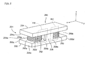
- FIG 5 is a perspective view of a magnetic element according to a second embodiment of the present invention.
- FIG 6 shows an exploded perspective view of the magnetic element according to the second embodiment of the present invention.
- the X-axis direction is front (the front side)
- the Y-axis direction is left (the left side)
- the Z-axis direction is up (the top side).
- the inductance element 200 as a magnetic element has a core unit 201 and two coils 202, 203.
- the core unit 201 has planar cores 204, 205, center cores 206, 207, and a side core 208.
- the planar cores 204, 205 overall are vertically flattened rectangular bodies, both having substantially the same shape.
- the center cores 206, 207 are columnar in shape, having their long directions in the vertical direction, and both having substantially the same shape.
- the side core 208 is a substantially weight-shaped column in cross-section, in a surface along an X-Y plane.
- the side core 208 has lateral side surfaces 208a, 208b and a top end surface 208c that are flat, and recessed portions 208g, 208h that are curved in the shape of inward-facing arcs are formed in front and rear side surfaces 208e, 208f.
- the side core 208 is columnar in shape, and its cross-section has the same shape from a portion 208d that joins the planar core 205 to the top end surface to 208c.
- the planar core 205, the center cores 206, 207, and the side core 208 are formed into a single integrated unit by sintering, or the like, magnetic powder such as ferrite.
- the center cores 206, 207 and the side core 208 are mounted so as to project upwardly from a wide surface 205a on the top side of the planar core 205.
- the side core 208 is disposed at a center portion in a longitudinal direction that is also the long direction of the planar core 205.
- a width of the side core 208 in a lateral direction is the same as a width of the planar core 205 in the lateral direction, and the lateral side surfaces 208a, 208b are each disposed so as to be flush with lateral long side surfaces 205b, 205c of the planar core 205.
- the center cores 206, 207 are each disposed on both proximal and distal sides of the side core 208, at positions substantially at the center between the side core 208 and short side surfaces 205d, 205e of the planar core 205 that form both end surfaces in the long direction of the planar core 205.
- the coils 202, 203 are wound wire coils formed by winding copper wire in a cylindrical shape, having hollow portions 202a, 203a formed in the inner peripheries thereof.
- the coils 202, 203 are each set on the planar core 205 by inserting the center cores 206, 207 into the hollow portions 202a, 203a.
- center cores 206, 207 and the side core 208 are each disposed at positions that secure a distance, such that the side core 208 and the coils 202, 203 do not interfere with each other when the center cores 206, 207 are inserted into the coils 202, 203.
- the wide surface 204a of the planar core 204 is placed against top end surfaces 206a, 207a of the center cores 206, 207 and, the top end surface 208c of the side core 208 and the joined surfaces are adhesively fixed in place with an adhesive agent, thus forming the planar cores 204, 205, the side core 208 and the center cores 206, 207 into a single integrated unit so as to form the core unit 201.
- a magnetic field (magnetic flux F B) that passes through the center core 206, the planar core 204, the side core 208, the planar core 205 and the center core 206 is produced.
- a magnetic field (magnetic flux F C) that passes through the center core 207, the planar core 204, the side core 208, the planar core 205 and the center core 207 is produced.
- the center core 206, the planar core 204, the side core 208, the planar core 205, and the center core 206 form a closed magnetic path.
- center core 207, the planar core 204, the side core 208, the planar core 205, and the center core 207 also form a closed magnetic path. It should be noted that the direction of the magnetic flux changes with the direction of the electric currents passing through the coils 202, 203.
- the side coil 208 is disposed between the center core 206 and the center core 207 that are longitudinally disposed.
- the side core 208 is disposed distally of the center core 206 and proximally of the center core 207. Therefore, an open portion 209a is formed between the planar core 204 and the planar core 205 in front of and to the lateral sides of the center core 206.
- an open portion 209b is formed between the planar core 204 and the planar core 205 behind and to the lateral sides of the center core 207.
- substantially triangular spaces 210a whose hypotenuses are arc-shaped are formed as dead spaces between the lateral side surfaces on the rear side of the coil 202 and the edges 205f, 205g, as indicated by the dotted lines in FIG 6 .
- substantially triangular spaces 210b whose hypotenuses are arc-shaped are formed as dead spaces between the lateral side surfaces on the front side of the coil 203 and the edges 205f, 205g, again as indicated by the dotted lines in FIG. 6 .
- the recessed portion 208g formed in the front side surface 208e of the side core 208 is a curved surface, concave in the shape of a concentric arc of greater curve than the outer peripheral surface 202b of the coil 202 so as to accommodate the shape of the outer peripheral surface 202b of the coil 202.
- the recessed portion 208h formed in the rear side surface 208f of the side core 208 is a curved surface, concave in the shape of a concentric arc of greater curve than the outer peripheral surface 203b of the coil 203 so as to accommodate the shape of the outer peripheral surface 203b of the coil 203.
- the side core 208 is shaped so as to extend into the spaces 210a, 210b as the side core 208 extends toward the sides of the side surfaces 208a, 208b from a lateral center side.
- the cross-sectional area of the side core 208 that is, the surface area of the top end surface 208c
- the cross-sectional area of the side core 208 can be increased without decreasing the space for the disposition of the coils 202, 203 (that is, the so-called winding frame).
- the cross-sectional area of the side core 208 can be increased without decreasing the size of the coils 202, 203. Therefore, it results in making it difficult for magnetic saturation of the magnetic fluxes F B, F C passing from the planar core 204 through the side core 208 to the planar core 205 to arise.
- the number of windings of the coils 202, 203 can be increased, thus enabling a large inductance value to be obtained.
- the thickness of the winding wire of the coils 202, 203 can be increased, thus aiding direct current resistance reduction.
- the side core 208 extends into the spaces 210a, 210b that are dead spaces, the cross-sectional area of the side core 208 increases. As a result, the mounting surface area of the inductance element 200 is not increased. In other words, in the inductance element 200, the surface areas of the wide surfaces 204a, 205c of the planar cores 204, 205 are the mounting surface areas. The cross-sectional area of the side core 208 is increased by extending the side core 208 into the spaces 210a, 210b; therefore, the surface areas of the wide surfaces 204a, 205a of the planar cores 204, 205 do not increase.
- a cross-sectional area (surface area of the top end surface 208c) S4 of the side core 208 with respect to a cross-sectional area S5 of the center core 206, that is, the surface area of the top end surface 206a, or a cross-sectional area S5 of the center core 207, that is, the surface area S5 of the top end surface 207 a, such that S5 + S5 ⁇ S4 ⁇ 5 x (S5 + S5), it is possible to effectively make it more difficult for magnetic saturation to occur in the side core 208.
- the cross-sectional area of the side core 208 from 1 to 5 times the total combined cross-sectional areas of the center core 206 and the center core 207, it is possible to effectively make it more difficult for magnetic saturation to occur in the side core 208.
- the thicknesses between the center core 206 and the center core 207 are different, then by making the cross-sectional area S6 of the planar cores 204, 205 from 1 to 5 times the cross-sectional area of the thicker of the two winding coils, it is possible to effectively make it more difficult for magnetic saturation to occur in the planar cores 204, 205.
- a height in a vertical direction of the center cores 206, 207 may be made somewhat shorter than a height in a vertical direction of the side core 208 (for example, 1 mm shorter), the planar core 204 adhered to the top end surface 208c of the side core 208 such that the planar core 204 is supported only by the side core 208, and an empty space formed as a magnetic gap between the top end surface 206a of the center core 206 and the top end surface 207a of the center core 207 and the wide surface 204a on the other.
- the superimposed direct current characteristics of the inductance element 200 can be improved. It should be noted that the magnetic gap between the top end surfaces 206a, 207a of the center cores 206, 207 and the planar core 204 may be a spacer gap.
- a height in the vertical direction of the side core 208 may be made somewhat shorter than the height in the vertical direction of the center cores 206, 207, the planar core 204 adhered to the top end surfaces 206a, 207a of the center cores 206, 207 such that the planar core 204 is supported only by the center cores 206, 207, and an empty space formed as a magnetic gap between the top end surface 208c of the side core 208 and the wide surface 204a.
- the magnetic gap between the top end surface 208c of the side core 208 and the wide surface 204a may be a spacer gap.
- both the center cores 206, 207 and the side core 208 are provided on the one planar core 205
- the center cores 206, 207 alone may be provided on the planar core 205 and the side core 208 may be provided on the other planar core 204.
- the planar core 205 and the center cores 206, 207 are formed as a single integrated unit by sintering, or the like, magnetic powder such as ferrite
- the side core 208 and the planar core 204 are similarly formed as a single integrated unit by sintering, or the like, magnetic powder such as ferrite.
- the top end surfaces 206a, 207a of the center cores 206, 207 and the planar core 204 are attached to each other with an adhesive agent
- the bottom end surface of the side core 208 (the surface that corresponds to the portion that attaches to the planar core 205 in FIG 5 and FIG 6 ) and the planar core 205 are similarly attached to each other with an adhesive agent so as to form the core unit 201.
- an empty space may be formed as a magnetic gap between the top end surfaces 206a, 207a of the center cores 206, 207 and the planar core 204, or between the bottom end surface of the side core 208 and the planar core 205.
- the magnetic gap between the top end surfaces 206a, 207a of the center cores 206, 207 and the planar core 204, or between the bottom end surface of the side core 208 and the planar core 205 may be a spacer gap.
- the center cores 206, 207, the side core 208 and the planar core 205 are formed as a single integrated unit, alternatively, the center cores 206, 207, the planar core 205 and the side core 208 may each be formed separately. In that case, by attaching the center cores 206, 207, the planar cores 204, 205, and the side core 208 to each other with an adhesive agent, as a whole they form the core unit 201 constituted as a single integrated unit.
- an empty space may be formed as a magnetic gap between one end surface of the center cores 206, 207 and one of the planar cores 204 or 205, or between one end surface of the side core 208 and one of the planar cores 204 or 205.
- the magnetic gap may be a spacer gap.
- At least one of the cores that comprise the core unit 201 may be formed by compression-molding of permalloy, Sendust, or other such powder, in a construction that uses a so-called compressed metal powder core.
- the saturation magnetic flux density can be increased, thus enabling the inductance element 200 to be made more compact.
- planar cores 204, 205 of compressed metal powder enables the cross-sectional areas S6 of the planar cores 204, 205 to be decreased, which in turn enables the thicknesses of the planar cores 204, 205 to be reduced. Therefore, the vertical height of the inductance element 200 can be reduced.
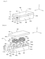
- FIG 7 is a perspective view of the magnetic element according to the third embodiment of the present invention.
- FIG 8 is an exploded perspective view of the magnetic element according to the third embodiment of the present invention.
- the X-axis direction is front (the front side)
- the Y-axis direction is left (the left side)
- the Z-axis direction is up (the top side).
- the inductance element 300 as a magnetic element has a core unit 301 and two coils 302, 303.
- the core unit 301 has planar cores 304, 305, center cores 306, 307, and side cores 308, 309.
- the planar cores 304, 305 overall are vertically flattened rectangular bodies, both having substantially the same shape.
- the center cores 306, 307 are columnar in shape, having their long directions in the vertical direction, and both having substantially the same shape.
- the side cores 308, 309 are mounted on both ends of the planar core 305 in a longitudinal direction, which is the long direction, of the planar core 305. Moreover, the side cores 308, 309 are substantially saddle-shaped columns in cross-section, in a surface along an X-Y plane. In other words, the side core 308 has a front side surface 308a, lateral side surfaces 308b, 308c and a top end surface 308d that are flat, and a recessed portion 308g that is curved in the shape of an inward- (front-) facing arc is formed in a rear side surface 308f.
- side core 309 similarly has a rear side surface 309a, lateral side surfaces 309b, 309c and a top end surface 309d that are flat, and a recessed portion 309g that is curved in the shape of an inward- (rear-) facing arc is formed in a front side surface 309f.
- the side core 308 is columnar in shape, and its cross-section has the same shape from a portion 308e that joins the planar core 305 to the top end surface to 308d.
- the side core 309 also is columnar in shape, and its cross-section has the same shape from a portion 309e that joins the planar core 305 to the top end surface 309d.
- the planar core 305, the center cores 306, 307, and the side cores 308, 309 are formed into a single integrated unit by sintering, or the like, magnetic powder such as ferrite.
- the center cores 306, 307 and the side cores 308, 309 are each mounted so as to project upwardly from a wide surface 305a on the top side of the planar core 305.
- the side core 308 and the center core 306, and the side core 309 and the center core 307, in their positions and their shapes, are arranged symmetrically about a center of the planar core 305 in the longitudinal direction of the planar core 305.
- the side core 308 is disposed on where its front side surface 308a is flush with a short side surface 306a that forms one end surface in the long direction of the planar core 305 on the front side of the wide surface 305a of the planar core 305. Moreover, a width of the side core 308 in a lateral direction is the same as a width of the planar core 305 in the lateral direction. Lateral side surfaces 308b, 308c of the side core 308 are each disposed so as to be flush with lateral long side surfaces 305c, 305d of the planar core 305.
- the side core 309 is disposed on where its rear side surface 309a is flush with a short side surface 305e that forms the other end surface in the long direction of the planar core 305 on the rear side of the wide surface 305a of the planar core 305. Moreover, a width of the side core 309 in the lateral direction is the same as the width of the planar core 305 in the lateral direction. Lateral side surfaces 309b, 309c of the side core 309 are each disposed so as to be flush with the lateral long side surfaces 305c, 305d of the planar core 305.
- the center core 306 is disposed at substantially the center between the center of the planar core 305 in the longitudinal direction and the side core 308.
- the center core 307 is also disposed at substantially the center between the center of the planar core 305 in the longitudinal direction and the side core 309.
- the coils 302, 303 are wound wire coils formed by winding copper wire in a cylindrical shape, having hollow portions 302a, 303a formed in the inner peripheries thereof.
- the coils 302, 303 are each set on the planar core 305 by inserting the center cores 306, 307 into the hollow portions 302a, 303a.
- the center cores 306, 307 and the side cores 308, 309 are each disposed at positions that secure a distance, such that the side cores 308, 309 and the coils 302, 303 do not interfere with each other, or the coils 302, 303 themselves do not interfere with each other, when the center cores 306, 307 are inserted into the coils 302, 303.
- the center core 306 and the center core 307 are mounted a predetermined distance apart so that the coils 302, 303 do not interfere with each other.
- the center cores 306, 307 and the side cores 308, 309 are also mounted a predetermined distance apart so that the coils 302, 303 do not interfere with the side cores 308, 309.
- the wide surface 304a of the planar core 304 is placed against top end surfaces 306a, 307a of the center cores 306, 307 and the top end surfaces 308d, 309d of the side cores 308, 309 and the joined surfaces are adhesively fixed in place with an adhesive agent, thus forming the planar cores 304, 305, the side cores 308, 309 and the center cores 306, 307 into a single integrated unit so as to form the core unit 301.
- the core unit 301 when an electric current is passed through the coil 302, a magnetic field (magnetic flux F D) that passes through the center core 306, the planar core 304, the side core 308, the planar core 305 and the center core 306 is produced.
- a magnetic field (magnetic flux F E) that passes through the center core 307, the planar core 304, the side core 309, the planar core 305 and the center core 307 is produced.
- the center core 306, the planar core 304, the side core 308, the planar core 305, and the center core 306 form a closed magnetic path.
- center core 307, the planar core 304, the side core 309, the planar core 305, and the center core 307 also form a closed magnetic path. It should be noted that the direction of the magnetic flux changes with the direction of the electric currents passing through the coils 302, 303.
- the side cores 308, 309 are disposed in the longitudinal direction of the planar cores 304, 305, sandwiching the center cores 306, 307 therebetween. Therefore, an open portion 310 is formed between the planar core 304 and the planar core 305 and to the lateral sides of the center cores 306, 307. As a result, the ends of the coils 302, 303 can be easily drawn out of the core unit 301 from the open portion 310.
- substantially triangular spaces 311a whose hypotenuses are arc-shaped are formed as dead spaces between the lateral side surfaces on the front side of the coil 302 and the edges 305f, 305g, as indicated by the dotted lines in FIG 8 .
- substantially triangular spaces 311b whose hypotenuses are arc-shaped are formed as dead spaces between the lateral side surfaces on the rear side of the coil 303 and the edges 305f, 305g, again as indicated by the dotted lines in FIG 8 .
- the recessed portion 308g formed in the rear side surface 308f of the side core 308 is a curved surface, concave in the shape of a concentric arc of greater curve than the outer peripheral surface 302b of the coil 302 so as to accommodate the shape of the outer peripheral surface 302b of the coil 302.
- the side core 308 is shaped so as to extend into the spaces 311 a as the side core 308 extends toward the sides of the side surfaces 308b, 308c from a lateral center side, with a portion of the coil 302 contained in the recessed portion 308g.
- the cross-sectional area of the side core 308, that is, the surface area of the top end surface 308d can be increased without decreasing the winding frame for the disposition of the coil 302.
- the recessed portion 309g formed in the front side surface 309f of the side core 309 is a curved surface, concave in the shape of a concentric arc of greater curve than the outer peripheral surface 303b of the coil 303 so as to accommodate the shape of the outer peripheral surface 303b of the coil 303.
- the side core 309 is shaped so as to extend into the spaces 311b as the side core 309 extends toward the sides of the side surfaces 309b, 309c from a lateral center side, with a portion of the coil 303 contained in the recessed portion 309g.
- the cross-sectional area of the side core 309 as well can be increased without decreasing the winding frame for the disposition of the coil 303.
- the cross-sectional area of the side cores 308, 309 can be increased without decreasing the size of the coils 302, 303. Therefore, it results in making it difficult for magnetic saturation of the magnetic flux F D passing from the planar core 304 through the side core 308 to the planar core 305 to arise. Similarly, it results in making it difficult for magnetic saturation of the magnetic flux F E passing from the planar core 304 through the side core 309 to the planar core 305 to arise.
- the number of windings of the coils 302, 303 can be increased, thus enabling a large inductance value to be obtained.
- the thickness of the winding wire of the coils 302, 303 can be increased, thus aiding direct current resistance reduction.
- the side cores 308, 309 extend into the spaces 311a, 311b that are dead spaces, and therefore their cross-sectional area increases. As a result, the mounting surface area of the inductance element 300 is not increased. In other words, in the inductance element 300, the surface areas of the wide surfaces 304a, 305a of the planar cores 304, 305 are the mounting surface areas. By extending the side cores 308, 309 into the spaces 311a, 311b, the cross-sectional area of the side cores 308, 309 is increased, and therefore the surface areas of the wide surfaces 304a, 305a of the planar cores 304, 305 do not increase.
- the thicknesses of the center core 306 and the center core 307 are different, then by making the cross-sectional area S9 of the planar cores 304, 305 from 1 to 5 times the cross-sectional area of the thicker of the two winding coils it is possible to effectively make it more difficult for magnetic saturation to occur in the planar cores 304, 305.
- a height in a vertical direction of the center cores 306, 307 may be made somewhat shorter than a height in a vertical direction of the side cores 308, 309 (for example, 1 mm shorter), the planar core 304 adhered to the top end surfaces 308d, 309d of the side cores 308, 309 such that the planar core 304 is supported only by the side cores 308, 309, and an empty space formed as a magnetic gap between the top end surfaces 306a, 307a of the center cores 306, 307, on the one hand, and the wide surface 304a on the other.
- the superimposed direct current characteristics of the inductance element 300 can be improved. It should be noted that the magnetic gap between the top end surfaces 306a, 307a of the center cores 306, 307 and the planar core 304 may be a spacer gap.
- a height in the vertical direction of the side cores 308, 309 may be made somewhat shorter than the height in the vertical direction of the center cores 306, 307, the planar core 304 adhered to the top end surfaces 306a, 307a of the center cores 306, 307 such that the planar core 304 is supported only by the center cores 306, 307, and an empty space formed as a magnetic gap between the top end surfaces 308d, 309d of the side cores 308, 309 and the wide surface 304a.
- the magnetic gap between the top end surfaces 308d, 309d of the side cores 308, 309 and the wide surface 304a may be a spacer gap.
- both the center cores 306, 307 and the side cores 308, 309 are mounted on the one planar core 305
- the center cores 306, 307 alone may be mounted on the planar core 305
- the side cores 308, 309 may be mounted on the other planar core 304.
- the planar core 305 and the center cores 306, 307 are formed as a single integrated unit by sintering, or the like, magnetic powder such as ferrite
- the side cores 308, 309 and the planar core 304 are similarly formed as a single integrated unit by sintering, or the like, magnetic powder such as ferrite.
- the top end surfaces 306a, 307a of the center cores 306, 307 and the planar core 304 are attached to each other with an adhesive agent
- the bottom end surfaces of the side cores 308, 309 (the surfaces that correspond to the portions 308e, 309e that attach to the planar core 305 in FIG 7 and FIG 8 ) and the planar core 305 are similarly attached to each other with an adhesive agent so as to form the core unit 301.
- an empty space may be formed as a magnetic gap between the top end surfaces 306a, 307a of the center cores 306, 307 and the planar core 304, or between the respective bottom end surfaces of the side cores 308, 309 and the planar core 305.
- the magnetic gap between the top end surfaces 306a, 307a of the center cores 306, 307 and the planar core 304, or between the respective bottom end surfaces of the side cores 308, 309 and the planar core 305, may be a spacer gap.
- the center cores 306, 307, the side cores 308, 309, and the planar core 305 are formed as a single integrated unit
- the center cores 306, 307, the side cores 308, 309, and the planar core 305 may be each formed separately.
- an adhesive agent by attaching the center cores 306, 307, the planar cores 304, 305, and the side cores 308, 309 to each other with an adhesive agent, as a whole they form the core unit 301 constituted as a single integrated unit.
- an empty space may be formed as a magnetic gap between one end surface of the center cores 306, 307 and one of the planar cores 304 or 305, or between one end surface of the side cores 308, 309 and one of the planar cores 304 or 305.
- the magnetic gap may be a spacer gap.
- At least one of the cores that comprise the core unit 301 may be formed by compression-molding of permalloy, Sendust, or other such powder, in a construction that uses a so-called compressed metal powder core.
- the saturation magnetic flux density can be increased, thus enabling the inductance element 300 to be made more compact.
- planar cores 304, 305 of compressed metal powder enables the cross-sectional areas S9 of the planar cores 304, 305 to be decreased, which in turn enables the thicknesses of the planar cores 304, 305 to be reduced. Therefore, the vertical height of the inductance element 300 can be reduced.
- FIG 9 is a perspective view of the magnetic element according to a fourth embodiment of the present invention.
- FIG 10 is an exploded perspective view of the magnetic element according to the fourth embodiment of the present invention.
- the X-axis direction is front (the front side)
- the Y-axis direction is left (the left side)
- the Z-axis direction is up (the top side).
- the inductance element 400 as a magnetic element has a core unit 401 and two coils 402, 403.
- the core unit 401 has planar cores 404, 405, center cores 406, 407, and side cores 408, 409.
- the planar cores 404, 405 overall are vertically flattened rectangular bodies, both having substantially the same shape.
- the center cores 406, 407 are columnar in shape, with their long directions in the vertical direction, and both have substantially the same shape.
- the side cores 408, 409 are long and narrow in a longitudinal direction, and overall are substantially quadrangular columns.
- the center cores 406, 407, the planar core 405 and the side cores 408, 409 are formed into a single integrated unit by sintering, or the like, magnetic powder such as ferrite.
- the side cores 408, 409 and the center cores 406, 407 are each mounted so as to project upwardly from a wide surface 405a on a top side of the planar core 405.
- the side cores 408, 409 are mounted on both lateral ends of the planar core 405, which is the short direction of the planar core 405. Then, a left side surface 408a and front and rear end surfaces 408b, 408c of the side core 408 are flush with a left side surface 405b, which is one end surface in the short direction of the planar core 405, and front and rear end surfaces 405c, 405d of the planar core 405, respectively. With the side core 409 as well, a right side surface 409a and front and rear end surfaces 409b, 409c are flush with a right side surface 405e, which is the other end surface in the short direction of the planar core 405, and the front and rear end surfaces 405c, 405d, respectively.
- the coils 402, 403 are wound wire coils formed by winding copper wire in a cylindrical shape, with hollow portions 402a, 403a formed in the inner peripheries thereof.
- the coils 402, 403 are each set on the planar core 405 by inserting the center cores 406, 407 into the hollow portions 402a, 403a.
- the center cores 406, 407 are disposed in a direction alongside the side cores 408, 409, that is, parallel to the side cores 408, 409. In addition, the center cores 406, 407 are disposed at positions that secure a distance therebetween, such that, when the winding cores 406, 407 are inserted into the coils 402, 403, the side cores 408, 409 and the coils 402, 403 do not interfere with each other, or the coils 402, 403 do not interfere with each other.
- the center core 406 and the center core 407 are mounted a predetermined distance apart, such that the coils 402, 403 do not interfere with each other, and moreover, the center cores 406, 407 and the side cores 408, 409 are also mounted a predetermined distance apart, such that the coils 402, 403 do not interfere with the side cores 408, 409.
- the wide surface 404a of the planar core 404 is placed against top end surfaces 406a, 407a of the center cores 406, 407 and the top end surfaces 408d, 409d of the side cores 408, 409 and the joined surfaces are adhesively fixed in place with an adhesive agent, thus forming the planar cores 404, 405, the side cores 408, 409, and the center cores 406, 407 into a single integrated unit so as to form the core unit 401.
- a magnetic field (magnetic flux F F1) that passes through the center core 406, the planar core 404, the side core 408, the planar core 405 and the center core 406, and a magnetic field (magnetic flux F F2) that passes through the center core 406, the planar core 404, the side core 409, the planar core 405 and the center core 406, are produced.
- the center core 406, the planar core 404, the side core 408, the planar core 405, and the center core 406, as well as the center core 406, the planar core 404, the side core 409, the planar core 405, and the center core 406 both form closed magnetic paths.
- the direction of the magnetic flux changes with the direction of the electric current passing through the coils 402, 403.
- the side cores 408, 409 are mounted laterally of the center cores 406, 407. Therefore, an open portion 410a is formed in front of the center core 406, between the planar core 404 and the planar core 405. In addition, an open portion 410b is also formed behind the center core 407, between the planar core 404 and the planar core 405. As a result, the ends of the coil 402 can be easily drawn out of the core unit 401 from the open portion 410a, and similarly, the ends of the coil 403 can be easily drawn out of the core unit 401 from the open portion 410b.
- recessed portions 408e1, 408e2, 409e1, 409e2 are formed that are curved surfaces, concave in the shape of concentric arcs of greater curve than the outer peripheral surface 402b, 403b of the coils 402, 403 so as to accommodate the shape of the outer peripheral surfaces 402b, 403b of the coils 402, 403.
- Portions of the coil 402 are contained within the recessed portions 408e1 and 409e1.
- portions of the coil 403 are contained within the recessed portions 408e2 and 409e2.
- a lateral thickness of the side cores 408, 409 can be thickened in a direction from lateral side surfaces 405b, 405e of the planar core 405 side toward the coils 402, 403 without interfering with the coils 402, 403.
- a cross-sectional area of the side cores 408, 409 that is, the surface area of the top end surfaces 408d, 409d, can be increased without decreasing the space (the winding frame) for the winding of the coils 402, 403.
- the cross-sectional area of the side cores 408, 409 can be increased without decreasing the size of the coils 402, 403. Therefore, it results in making it difficult for magnetic saturation in the side cores 408, 409 to arise.
- the number of windings of the coils 402, 403 can be increased, thus enabling a large inductance value to be obtained.
- the thickness of the winding wire of the coils 402, 403 can be increased, thus aiding direct current resistance reduction.
- the recessed portions 408e1, 408e2, 409e1, 409e2 allow the side cores 408, 409 to be made thicker on the inside of the lateral direction of the planar cores 404, 405 while avoiding a reduction in the winding frame.
- the mounting surface area of the inductance element 400 is not increased even if the cross-sectional area of the side cores 408, 409 is increased.
- the surface areas of the wide surfaces 404a, 405a of the planar cores 404, 405 are the mounting surface areas. Because the thicknesses of the side cores 408, 409 are increased in the lateral direction toward the coils 402, 403, surface areas of the wide surfaces 404a, 405a of the planar cores 404, 405 are not increased.
- the thicknesses of the center core 406 and the center core 407 are different, then by making the cross-sectional area S10 of the side cores 408, 409 from 2 to 10 times the cross-sectional area of the thicker of the two center cores, it is possible to effectively make it more difficult for magnetic saturation to occur in the side cores 408, 409.
- the cross-sectional area S12 of the planar cores 404, 405 from 1 to 5 times the cross-sectional area of the thicker of the two center cores, it is possible to effectively make it more difficult for magnetic saturation to occur in the planar cores 404, 405.
- a height in a vertical direction of the center cores 406, 407 may be made somewhat shorter than a height in a vertical direction of the side cores 408, 409 (for example, 1 mm shorter), the planar core 404 adhered to the top end surfaces 408d, 409d of the side cores 408, 409 such that the planar core 404 is supported only by the side cores 408, 409, and an empty space formed as a magnetic gap between the top end surfaces 406a, 407a of the center cores 406, 407, on the one hand, and the wide surface 404a on the other.
- the superimposed direct current characteristics of the inductance element 400 can be improved. It should be noted that the magnetic gap between the top end surfaces 406a, 407a of the center cores 406, 407 and the planar core 404 may be a spacer gap.
- the height in the vertical direction of the side cores 408, 409 may be made somewhat shorter than the height in the vertical direction of the center cores 406, 407, the planar core 404 adhered to the top end surfaces 406a, 407a of the center cores 406, 407 such that the planar core 404 is supported only by the center cores 406, 407, and an empty space formed as a magnetic gap between the top end surfaces 408d, 409d of the side cores 408, 409 and the wide surface 404a.
- the magnetic gap between the top end surfaces 408d, 409d of the side cores 408, 409 and the wide surface 404a may be a spacer gap.
- both the center cores 406, 407 and the side cores 408, 409 are mounted on the one planar core 405, alternatively, the center cores 406, 407 alone may be mounted on the planar core 405 and the side cores 408, 409 may be mounted on the other planar core 404.
- the planar core 405 and the center cores 406, 407 are formed as a single integrated unit by sintering, or the like, magnetic powder such as ferrite
- the side cores 408, 409 and the planar core 404 are similarly formed as a single integrated unit by sintering, or the like, magnetic powder such as ferrite.
- the top end surfaces 406a, 407a of the center cores 406, 407 and the planar core 404 are attached to each other with an adhesive agent
- the bottom end surfaces of the side cores 408, 409 (the surfaces that are the portions joined to the planar core 405 in FIG. 9 and FIG 10 ) and the planar core 405 are similarly attached to each other with an adhesive agent, so as to form the core unit 401.
- an empty space may be formed as a magnetic gap between the top end surfaces 406a, 407a of the center cores 406, 407 and the planar core 404, or between the bottom end surfaces of the side cores 408, 409 and the planar core 405.
- the magnetic gap between the top end surfaces 406a, 407a of the center cores 406, 407 and the planar core 404, or between the bottom end surfaces of the side cores 408, 409 and the planar core 405, may be a spacer gap.
- the center cores 406, 407, the planar core 405, and the side cores 408, 409 are shown formed as a single integrated unit, alternatively, the center cores 406, 407, the planar core 405 and the side cores 408, 409 may be each formed separately. In that case, by attaching the center cores 406, 407, the planar cores 404, 405, and the side cores 408, 409 to each other with an adhesive agent, as a whole they form the core unit 401 constituted as a single integrated unit.
- an empty space may be formed as a magnetic gap between one end surface of the center cores 406, 407 and one of the planar cores 404 or 405, or between one end surface of the side cores 408, 409 and one of the planar cores 404 or 405.
- the magnetic gap may be a spacer gap.
- At least one of the cores that comprise the core unit 401 may be formed by compression-molding of permalloy, Sendust, or other such powder, in a construction that uses a so-called compressed metal powder core.
- the compressed metal powder core portion of the core unit 401 the saturation magnetic flux density can be increased, thus enabling the inductance element 400 to be made more compact.
- planar cores 404, 405 of compressed metal powder enables the cross-sectional area S12 of the planar cores 404, 405 to be decreased, which in turn enables the thicknesses of the planar cores 404, 405 to be reduced. Therefore, the vertical height of the inductance element 400 can be reduced.
- an adhesive agent mixing magnetic powder such as ferrite with an epoxy resin or an acryl resin may be applied around the coils 102 (202, 203, 302, 303, 402, 403) to prevent magnetic flux leakage.
- the magnetic characteristics may be changed by adjusting the amount of adhesive agent applied as appropriate.
- the space in the inductance element 100 (200, 300, 400) between the coil(s) 102 (202, 203, 302, 303, 402, 403), and the interior(s) of the core unit(s) 101 (201, 301, 401) may be filled with an adhesive agent containing magnetic powder to prevent magnetic flux leakage.
- the magnetic characteristics may be changed by adjusting the amount of adhesive agent supplied as appropriate.
- ferrites such as Ni-Zn ferrite and Mn-Zn ferrite, metallic magnetic material, amorphous magnetic material and the like may be used as the magnetic material used to form the core unit 101 (201, 301, 401) in the embodiments described above.
- making the core unit 101 (201, 301, 401) of compressed metal powder enables the saturation magnetic flux density to be increased, thus further enabling the inductance element 100 (200, 300, 400) to be made even more compact.
- the present invention is not limited to the one or two in the embodiments described above, and therefore there may be three or more coils.
- the recessed portions 106g, 208g, 208h, 308g, 308h, 408b1, 408b2, 409b1, 409b2 are arc-shaped concave surfaces, such recessed portions are not limited to an arc shape, and consequently, may be oval, or rectangular.
- the arc shape reduces the gap with the coil, thus enabling magnetic flux leakage to be effectively reduced.
Landscapes
- Engineering & Computer Science (AREA)
- Power Engineering (AREA)
- Microelectronics & Electronic Packaging (AREA)
- Chemical & Material Sciences (AREA)
- Composite Materials (AREA)
- Coils Or Transformers For Communication (AREA)
Abstract
Description
- The present invention relates to a magnetic element.
- Conventionally, many magnetic elements having a structure in which a rectangular or cylindrical ring core is disposed around the periphery of a circular drum core, in which a coil is wound around a winding axis, are known (see, for example, Japanese patent laid-open publication
2006-73847 - As a solution to this problem, a configuration is disclosed in Japanese patent laid-open publication
2004-111754 -
FIGS. 11A-11C show an exploded perspective view of a magnetic element 500 of the Japanese patent laid-open publication2004-111754 first core 501, a lowersecond core 502, and twocoils - The
first core 501, shown inFIG 11(A) , comprises aflat plane portion 501a; three planar side legs, 501b, 501b, and 501b, which project from a pair of opposed short ends as well as from the middle of theflat plane portion 501a; and columnarcentral legs recessed portions adjacent side legs side leg 501b is provided. - Each of the two
coils FIG 11(B) is an edgewise coil that is formed by winding rectangular wires coated with insulation. The insulation is peeled back from the beginnings and the ends of the windings of thecoils ends - The
second coil 502 shown inFIG. 11C has a rectangular, flat plane shape having short and long sides of lengths substantially identical to those of the short and long sides of thefirst core 501. - The coils 503,504 fit into the
recessed portions first core 501, in a state in which thecentral legs center openings coils recessed portions first core 501, thesecond core 502 and thefirst core 501 are brought together, and therecessed portions second core 502. - Therefore, on both sides in the winding axis direction of the
coils flat plane portion 501a of thefirst core 501 and thesecond core 502 are disposed. In addition, in directions perpendicular to the winding axis ofcoil 503,side legs coil 503, and moreover, in directions perpendicular to the winding axis ofcoil 504,side legs coil 504. In other words, in the four directions of thecoil 503, a closed magnetic path is formed by theflat plane portion 501a of thefirst core 501, thesecond core 502, theside legs coil 504, a closed magnetic path is formed by theflat plane portion 501a of thefirst core 501, thesecond core 502, theside legs - By contrast, in the
recessed portion 501c in which thecoil 503 is holded, theopenings recessed portion 501c in which thecoil 504 is holded, theopenings - As a result, from these
openings 501 e, 50 1 e, 501e and 501 e, the ends of thecoils - However, with the magnetic element having the structure disclosed in Japanese Patent Laid-open publication
2004-111754 side legs - If the thicknesses of the
side legs side legs coils side legs central legs coils coils side legs coils - In order to solve problems described above, the present invention has as its object to provide a magnetic element the ends of the coil of which can be drawn out from the core easily, is compact, and further, is one in which magnetic saturation does not arise easily. In addition, the present invention has as its object to provide a magnetic element that relaxes restrictions on the number of windings in the coil and thereby enables a large inductance value to be obtained, or, alternatively, even if the number of windings is increased, relaxes restrictions on the thickness of the winding wire used so as to enable direct current resistance reduction.
- To achieve the above-described object, the present invention provides a magnetic element comprising a wound coil, a core body having a center core inserted into the inner periphery of the coil, planar cores disposed at both ends of the center core, and a side core disposed between the planar cores and on an outside periphery of the coil. The side core is disposed so as to form an open area between the two planar cores around the coil, with a recessed portion formed in a surface of the side core facing the coil in which the coil is partially contained.
- Giving the magnetic element such a configuration enables the ends of the coil to be easily drawn out of the core body from the open area. In addition, forming a recessed portion in the surface of the side core that faces the coil in which the coil is partially contained enables the magnetic element to remain compact, and moreover, enables the cross-sectional area of the side core to be increased; as a result, this makes it possible to prevent easy occurrence of magnetic saturation. In addition, because it is possible to secure a distance between the center core and the side core, restrictions on the number of windings is relaxed, thereby enabling a large inductance value to be obtained. Or, alternatively, even if the number of windings is increased, restrictions on the thickness of the winding wire used are relaxed, thereby enabling direct current resistance reduction to be achieved.
- In another aspect of the present invention, the side core and the center core form a single integrated unit with at least one of the two planar cores.
- Configuring the magnetic element as described above, in addition to reducing the number of components, enables to reduce leakage magnetic flux because the side core and the center core form a single integrated unit with at least one of the two planar cores, and therefore these joint sections form a single integrated unit.
- In another aspect of the present invention, a relation between a cross-sectional area S1 of the side core and a cross-sectional area S2 of the center core is such that S2 ≤ S1 ≤ 5 x S2.
- Configuring the magnetic element as described above enables to make it more difficult for magnetic saturation to occur.
- In another aspect of the present invention, a relation between the cross-sectional area S2 of the center core and a cross-sectional area S3 of the planar core is such that S2 ≤ S3 ≤ 5 x S2.
- Configuring the magnetic element as described above enables to make it more difficult for magnetic saturation to occur.
- In another aspect of the present invention, the side core is provided at a center of the planar core in a long direction of the planar core, and the center core is provided at two locations between the side core and both ends of the planar core in the long direction thereof.
- Configuring the magnetic element as described above enables one magnetic element to generate two magnetic fields.
- In another aspect of the present invention, a relation between a cross-sectional area S4 of the side core and a cross-sectional area S5 of the center core is such that S5 + S5 ≤ S4 ≤ 5 x (S5 + S5).
- Configuring the magnetic element as described above enables to make it more difficult for magnetic saturation to occur.
- In another aspect of the present invention, a relation between the cross-sectional area S5 of the center core and a cross-sectional area S6 of the planar core is such that S5 ≤ S6 ≤ 5 x S5.
- Configuring the magnetic element as described above enables to make it more difficult for magnetic saturation to occur.
- In another aspect of the present invention, the side core is mounted at both ends of the planar core in the long direction thereof, and the center core is provided at two locations with a predetermined distance apart between the two side cores.
- Configuring the magnetic element as described above enables one magnetic element to generate two magnetic fields.
- In another aspect of the present invention, a relation between a cross-sectional area S7 of the side core and a cross-sectional area S8 of the center core is such that S8 ≤ S7 ≤ 5 x S8.
- Configuring the magnetic element as described above enables to make it more difficult for magnetic saturation to occur.
- In another aspect of the present invention, a relation between the cross-sectional area S8 of the center core and a cross-sectional area S9 of the planar core is such that S8 ≤ S9 ≤ 5 x S8.
- Configuring the magnetic element as described above enables to make it more difficult for magnetic saturation to occur.
- In another aspect of the present invention, a side core is mounted at both ends of the planar core in a short direction thereof, and the center core is provided at two locations with a predetermined distance apart between the two side cores in parallel direction.
- Configuring the magnetic element as described above enables one magnetic element to generate two magnetic fields.
- In another aspect of the present invention, a relation between a cross-sectional area S10 of the side core and a cross-sectional area S11 of the center core is such that S11 + S11 ≤ S10 ≤ 5 x (S11 + S11).
- Configuring the magnetic element as described above enables to make it more difficult for magnetic saturation to occur.
- In another aspect of the present invention, a relation between a cross-sectional area S11 of the center core and a cross-sectional area S12 of the planar core is such that S11 ≤ S12 ≤ 5 x S11.
- Configuring the magnetic element as described above enables to make it more difficult for magnetic saturation to occur.
- In another aspect of the present invention, an adhesive containing magnetic material is applied around the coil.
- By configuring the magnetic element as described above, the periphery of the coil is covered with an adhesive coating containing magnetic material, thus enabling leakage magnetic flux to be reduced.
- In another aspect of the present invention, at least one of the center core, the planar core and the side core is formed from compressed metal powder. Configuring the magnetic element as described above enables the saturation magnetic flux density to be increased, thus further enabling the magnetic element to be made more compact.
- With the present invention, a magnetic element the ends of the coil of which can be drawn out from the core easily, is compact, and further, is one in which magnetic saturation does not arise easily, can be obtained. In addition, with the present invention, a magnetic element can be obtained that relaxes restrictions on the number of windings in the coil and thereby enables a large inductance value to be obtained, or, alternatively, relaxes restrictions on the thickness of the winding wire used so as to achieve direct current resistance reduction even if the number of windings is increased. Other features, objects and advantages of the present invention will be apparent from the following description when taken in conjunction with the accompanying drawings, in which like reference characters designate the same or similar parts throughout the figures thereof.
-
FIG 1 is a perspective view of a magnetic element according to a first embodiment of the present invention; -
FIG 2 is an exploded perspective view of the magnetic element shown inFIG 1 ; -
FIG 3 is a view of a planar core as seen from above, showing a dead space between edges of the planar core and a coil, in the magnetic element shown inFIG 1 ; -
FIG 4 shows a construction in which only a center core is provided on one planar core, and a side core is provided on another planar core, in the core shown inFIG 1 ; -
FIG 5 shows a perspective view of a magnetic element according to a second embodiment of the present invention; -
FIG 6 shows an exploded perspective view of the magnetic element shown inFIG 5 ; -
FIG 7 shows a perspective view of a magnetic element, according to a third embodiment of the present invention; -
FIG 8 shows an exploded perspective view of the magnetic element shown inFIG 7 ; -
FIG 9 shows a perspective view of a magnetic element, according to a fourth embodiment of the present invention; -
FIG 10 shows an exploded perspective view of the magnetic element shown inFIG 9 ; and -
FIGS. 11A-11C show a configuration of the conventional art. - Preferred embodiments of the present invention will now be described, with reference to the accompanying drawings. It should be noted, however, that the present invention is not limited to the following embodiments.
- First, a description is given of a first embodiment of a magnetic element according to the present invention.
-
FIG. 1 is a perspective view of a magnetic element according to the first embodiment of the present invention. In addition,FIG 2 is an exploded perspective view of the magnetic element shown inFIG 1 . - An
inductance element 100 as a magnetic element has acore unit 101 and acoil 102. Thecore unit 101 hasplanar cores center core 105, and aside core 106. Theplanar cores center core 105, and both have substantially identical shapes. - In the following description, a direction from a
short side surface 104a to ashort side surface 104b of theplanar core 104 is referred to as the front (front side), the reverse direction thereof is referred to as the rear (rear side), a right-hand direction, looking from the rear toward the front, is referred to as right (right side), and a left-hand direction looking from the rear toward the front is referred to as left (left side). In addition, a direction in which theplanar core 103 is disposed with respect to theplanar core 104 is referred to as up (upper side) and the reverse direction thereof is referred to as down (lower side). In other words, in the drawings, the X-axis direction is front, the Y-axis direction is left, and the Z-axis direction is up. - The
center core 105 is a cylindrical column, with its long direction in the vertical direction. - The
side core 106 is substantially saddle-shaped column in cross-section along a plane in the lateral and longitudinal directions of theplanar core 104, in other words, along in the X-Y plane. That is, arear side surface 106a, left and rightlateral surfaces top end surface 106d of theside core 106 are all flat, with a recessedportion 106g curved in the shape of an inward-(rearward-) facing arc formed in afront side surface 106f. It should be noted that theside core 106 is columnar, and its shape in cross-section is the same from aportion 106e at which it joins theplanar core 104 to thetop end surface 106d. - The
planar core 104, thecenter core 105 and theside core 106 are formed into a single integrated unit by sintering, or the like, a magnetic powder such as ferrite. Thecenter core 105 and theside core 106 are mounted on an upperwide surface 104c of theplanar core 104 with projecting upwardly. Thecenter core 105 is mounted on substantially center of the upperwide surface 104c of theplanar core 104. - The
side core 106 is disposed backward of thecenter core 105. Therear side surface 106a is disposed so as to be flush with theshort side surface 104a of theplanar core 104. In addition, a width of theside core 106 in the lateral direction is the same as a width of theplanar core 104 in the lateral direction, andside surfaces side core 106 are disposed so as to be flush with the laterallong side surfaces 104d, 140e of theplanar core 104. - The
coil 102 is a wound wire coil formed by winding copper wire in a cylindrical shape, having ahollow portion 102a formed in the inner periphery thereof. Thecoil 102 is set on theplanar core 104 by inserting the windingcore 105 into thehollow portion 102a. - It should be noted that the
center core 105 and theside core 106 are each disposed at positions that secure a distance, such that theside core 106 and thecoil 102 do not interfere with each other when thecenter core 105 is inserted into thecoil 102. - After the
center core 105 is inserted into thecoil 102, awide surface 103a of theplanar core 103 is placed against atop end surface 105a of thecenter core 105, and thetop end surface 106d of theside core 106 and the joined surfaces are adhesively fixed in place with an adhesive agent, thus forming theplanar cores core 105, and theside core 106 into a single integrated unit so as to form thecore unit 101. - Therefore, in the
core unit 101, when an electric current is passed through thecoil 102, a magnetic field (magnetic flux F A) that passes through thecenter core 105, theplanar core 103, theside core 106, theplanar core 104 and thecenter core 105 is produced. In other words, thecenter core 105, theplanar core 103, theside core 106, theplanar core 104, and thecenter core 105 form a closed magnetic path. It should be noted that the direction of the magnetic flux changes with the direction of the electric current passing through thecoil 102. - In the
core unit 101, anopen portion 107 is formed between theplanar core 103 and theplanar core 104 in the direction of front of and lateral to thecenter core 105 because theside core 106 is mounted on the side of theshort side surface 104a of theplanar core 104 that is positioned at backward of thecenter core 105. As a result, the ends of thecoil 102 can be easily drawn out of thecore unit 101 from theopen portion 107. - However, whereas
lateral edge portions wide surface 104c of theplanar core 104 on which thecoil 102 rests are straight lines, the outer peripheral surface of thecoil 102 is a cylindrical surface. Therefore, substantiallytriangular spaces 108 whose hypotenuses are arc-shaped are formed as dead spaces between the lateral side surfaces on the rear side of thecoil 102 and theedges FIG 3 . It should be noted thatFIG 3 shows theplanar core 104 as seen from above, with theside core 106 omitted to facilitate the description. - The recessed
portion 106g formed in thefront side surface 106f of theside core 106 is a curved surface, concave in the shape of a concentric arc of greater curve than the outerperipheral surface 102b of thecoil 102 so as to accommodate the shape of the outerperipheral surface 102b of thecoil 102. In other words, theside core 106 is shaped so as to extend into thespaces 108 as theside core 106 extends toward the sides of the side surfaces 106b, 106c from a lateral center side, with a portion of thecoil 102 contained in the recessedportion 106g. As a result, the cross-sectional area of theside core 106, that is, the surface area of thetop end surface 106d, can be increased without interfering with thecoil 102. - Consequently, it results in making it difficult for magnetic saturation of the magnetic flux Φ A passing from the
planar core 103 through theside core 106 to theplanar core 104 to arise. For example, if thefront side surface 106f of theside core 106 is made flat and theside core 106 is made into a rectangular solid without forming the recessedportion 106g in thefront side surface 106f, and an attempt is made to increase the cross-sectional area of theside core 106, the thickness of theside core 106 in the longitudinal direction increases overall, and the space for arranging the coil 102 (the so-called winding frame) decreases. - By contrast, by forming in the
front side surface 106f that faces thecoil 102 the concave recessedportion 106g so as to accommodate the shape of the outerperipheral surface 102b of thecoil 102, the cross-sectional area of theside core 106 can be increased without decreasing the winding frame. In other words, the cross-sectional area of theside core 106 can be increased without decreasing the size of thecoil 102. In addition, because a distance between thecenter core 105 and theside core 106 can be secured, the number of windings of thecoil 102 can be increased, thus enabling a large inductance value to be obtained. Or, alternatively, even if the number of windings is increased, the thickness of the winding wire of thecoil 102 can be increased, thus aiding direct current resistance reduction. - Moreover, even if the cross-sectional area of the
side core 106 is increased, the mounting surface area of theinductance element 100 is not increased because theside core 106 extends into thespaces 108 that are dead spaces. In other words, in theinductance element 100, the surface areas of thewide surfaces planar cores side core 106 into thespaces 108, the cross-sectional area of theside core 106 is increased, and therefore the surface areas of thewide surfaces planar cores - By making a cross-sectional area (
top end surface 106d) S1 of theside core 106, with respect to a cross-sectional area S2 of thecenter core 105, that is, the surface area of thetop end surface 105a, such that S2 ≤ S1 ≤ 5 x S2, it is possible to effectively make it more difficult for magnetic saturation to occur in theside core 106. - In addition, by making a cross-sectional area S3 of the vertical cross-section of
planar cores core 105, such that S2 ≤ S3≤5 x S2, it is possible to effectively make it more difficult for magnetic saturation to occur in theplanar cores - Further, a height in a vertical direction of the
center core 105 may be made somewhat shorter than a height in a vertical direction of the side core 106 (for example, 1 mm shorter), theplanar core 103 adhered to thetop end surface 106d of theside core 106, such that theplanar core 103 is supported only by theside core 106, and an empty space formed as a magnetic gap between thetop end surface 105a of thecenter core 105 and thewide surface 103a. By thus forming a magnetic gap between thetop end surface 105a of thecenter core 105 and theplanar core 103, the superimposed direct current characteristics of theinductance element 100 can be improved. It should be noted that the magnetic gap between thetop end surface 105a of thecenter core 105 and thewide surface 103a may be a so-called spacer gap, formed by sandwiching nonmagnetic insulation tape. - A height in the vertical direction of the
side core 106 may be made somewhat shorter than the height in the vertical direction of thecenter core 105, theplanar core 103 adhered to thetop end surface 105a of thecenter core 105, such that theplanar core 103 is supported only by thecenter core 105, and an empty space formed as a magnetic gap between thetop end surface 106d of theside core 106 and thewide surface 103a. The magnetic gap between thetop end surface 106d of theside core 106 and thewide surface 103a may be a spacer gap. - In the configuration shown in
FIG 1 and FIG 2 , both thecenter core 105 and theside core 106 are provided on oneplanar core 104. However, as shown inFIG 4 , thecenter core 105 alone may be mounted on the oneplanar core 104 and theside core 106 may be mounted on the otherplanar core 103. In this case, theplanar core 104 and thecenter core 105 are formed into a single integrated unit by sintering, or the like, magnetic powder such as ferrite, and theside core 106 and theplanar core 103 are also similarly formed into a single integrated unit by sintering, or the like, magnetic powder such as ferrite. By forming theplanar core 104 and thecenter core 105 into a single integrated unit by sintering or the like, the junction between theplanar core 104 and thecenter core 105 is completely formed into a single integrated unit, enabling leakage magnetic flux to be reduced. Similarly, by forming theside core 106 and the otherplanar core 103 into a single integrated unit by sintering or the like, the junction between theside core 106 and theplanar core 103 is completely formed into a single integrated unit, enabling leakage magnetic flux to be reduced. It should be noted that when both thecenter core 105 and theside core 106 are formed into a single integrated unit with the oneplanar core 104 by sintering or the like, similarly, the junctions between thecenter core 105 and theside core 106 with theplanar core 104 are formed completely into single integrated units, thus enabling leakage magnetic flux to be reduced. - Next, the
top end surface 105a of thecenter core 105 and theplanar core 103 are attached to each other with an adhesive agent, and a bottom end surface of the side core 106 (corresponding to the surface of theportion 106e joined to theplanar core 104 inFig.1 and 2 ) and theplanar core 104 are also similarly attached to each other with an adhesive agent so as to form thecore unit 101. Thus, by adopting a configuration that provides only thecenter core 105 on theplanar core 104, there is no obstruction around thecenter core 105, and the copper wire can be wound directly onto thecenter core 105 by machine. - It should be noted that, where, as here also, only the
center core 105 is mounted on theplanar core 104 and theside core 106 is mounted on theplanar core 103 side, by providing a difference in the heights of thecenter core 105 and theside core 106, an empty space may be formed as a magnetic gap between thetop end surface 105a of thecenter core 105 and theplanar core 103, or between the bottom end surface of theside core 106 and theplanar core 104. The magnetic gap between thetop end surface 105a of thecenter core 105 and theplanar core 103, or between the bottom end surface of theside core 106 and theplanar core 104, may be a spacer gap. - Moreover, in the configuration shown in
FIG 1 and FIG 2 , or inFIG 4 , thecenter core 105 and theside core 106 are formed as a single integrated unit with one of theplanar cores center core 105, theplanar cores side core 106 may each be formed separately. In that case, by attaching thecenter core 105, theplanar cores side core 106 to each other with an adhesive agent, so that they form a single integrated unit as a whole, thecore unit 101 may be constructed. In this case also, by providing a difference in the heights of thecenter core 105 and theside core 106, an empty space may be formed as a magnetic gap between one end surface of thecenter core 105 and one of theplanar cores side core 106 and one of theplanar cores - Moreover, at least one of the cores that comprise the
core unit 101, namely theplanar cores center core 105 and theside core 106, may be formed by compression-molding of permalloy, Sendust, or other such powder, in a construction that uses a so-called compressed metal powder core. In the compressed metal powder core portion of thecore unit 101, the saturation magnetic flux density can be increased, thus enabling theinductance element 100 to be made more compact. - In particular, forming the
planar cores planar cores planar cores inductance element 100 can be reduced. - A description is now given of a magnetic element according to a second embodiment of the present invention.
-
FIG 5 is a perspective view of a magnetic element according to a second embodiment of the present invention. In addition,FIG 6 shows an exploded perspective view of the magnetic element according to the second embodiment of the present invention. In the following description, as withFIG 1 through FIG 3 , in the drawings the X-axis direction is front (the front side), the Y-axis direction is left (the left side), and the Z-axis direction is up (the top side). - The
inductance element 200 as a magnetic element has acore unit 201 and twocoils core unit 201 hasplanar cores center cores side core 208. Theplanar cores center cores - The
side core 208 is a substantially weight-shaped column in cross-section, in a surface along an X-Y plane. In other words, theside core 208 haslateral side surfaces top end surface 208c that are flat, and recessedportions rear side surfaces side core 208 is columnar in shape, and its cross-section has the same shape from aportion 208d that joins theplanar core 205 to the top end surface to 208c. - The
planar core 205, thecenter cores side core 208 are formed into a single integrated unit by sintering, or the like, magnetic powder such as ferrite. Thecenter cores side core 208 are mounted so as to project upwardly from awide surface 205a on the top side of theplanar core 205. - The
side core 208 is disposed at a center portion in a longitudinal direction that is also the long direction of theplanar core 205. A width of theside core 208 in a lateral direction is the same as a width of theplanar core 205 in the lateral direction, and thelateral side surfaces planar core 205. Thecenter cores side core 208, at positions substantially at the center between theside core 208 andshort side surfaces planar core 205 that form both end surfaces in the long direction of theplanar core 205. - The
coils hollow portions coils planar core 205 by inserting thecenter cores hollow portions - It should be noted that the
center cores side core 208 are each disposed at positions that secure a distance, such that theside core 208 and thecoils center cores coils - After the
center cores respective coils wide surface 204a of theplanar core 204 is placed againsttop end surfaces center cores top end surface 208c of theside core 208 and the joined surfaces are adhesively fixed in place with an adhesive agent, thus forming theplanar cores side core 208 and thecenter cores core unit 201. - Therefore, in the
core unit 201, when an electric current is passed through thecoil 202, a magnetic field (magnetic flux F B) that passes through thecenter core 206, theplanar core 204, theside core 208, theplanar core 205 and thecenter core 206 is produced. In addition, when an electric current is passed through thecoil 203, a magnetic field (magnetic flux F C) that passes through thecenter core 207, theplanar core 204, theside core 208, theplanar core 205 and thecenter core 207 is produced. In other words, thecenter core 206, theplanar core 204, theside core 208, theplanar core 205, and thecenter core 206 form a closed magnetic path. Moreover, thecenter core 207, theplanar core 204, theside core 208, theplanar core 205, and thecenter core 207 also form a closed magnetic path. It should be noted that the direction of the magnetic flux changes with the direction of the electric currents passing through thecoils - The
side coil 208 is disposed between thecenter core 206 and thecenter core 207 that are longitudinally disposed. In other words, theside core 208 is disposed distally of thecenter core 206 and proximally of thecenter core 207. Therefore, anopen portion 209a is formed between theplanar core 204 and theplanar core 205 in front of and to the lateral sides of thecenter core 206. In addition, anopen portion 209b is formed between theplanar core 204 and theplanar core 205 behind and to the lateral sides of thecenter core 207. As a result, the ends of thecoil 202 can be easily drawn out of thecore unit 201 from theopen portion 209a. Likewise, the ends of thecoil 203 also can be easily drawn out of thecore unit 201 from theopen portion 209b. - However, whereas the
lateral edges wide surface 205a of theplanar core 205 on which thecoils coils triangular spaces 210a whose hypotenuses are arc-shaped are formed as dead spaces between the lateral side surfaces on the rear side of thecoil 202 and theedges FIG 6 . Moreover, withcoil 203 as well, substantiallytriangular spaces 210b whose hypotenuses are arc-shaped are formed as dead spaces between the lateral side surfaces on the front side of thecoil 203 and theedges FIG. 6 . - The recessed
portion 208g formed in thefront side surface 208e of theside core 208 is a curved surface, concave in the shape of a concentric arc of greater curve than the outerperipheral surface 202b of thecoil 202 so as to accommodate the shape of the outerperipheral surface 202b of thecoil 202. In addition, the recessedportion 208h formed in therear side surface 208f of theside core 208 is a curved surface, concave in the shape of a concentric arc of greater curve than the outerperipheral surface 203b of thecoil 203 so as to accommodate the shape of the outerperipheral surface 203b of thecoil 203. - In other words, the
side core 208 is shaped so as to extend into thespaces side core 208 extends toward the sides of theside surfaces coil 202 contained in the recessedportion 208g, and similarly, a portion of thecoil 203 is contained in the recessedportion 208h. - As a result, the cross-sectional area of the
side core 208, that is, the surface area of thetop end surface 208c, can be increased without decreasing the space for the disposition of thecoils 202, 203 (that is, the so-called winding frame). In other words, the cross-sectional area of theside core 208 can be increased without decreasing the size of thecoils planar core 204 through theside core 208 to theplanar core 205 to arise. In addition, because a distance between thecenter cores side core 208 can be secured, the number of windings of thecoils coils - Moreover, because the
side core 208 extends into thespaces side core 208 increases. As a result, the mounting surface area of theinductance element 200 is not increased. In other words, in theinductance element 200, the surface areas of thewide surfaces planar cores side core 208 is increased by extending theside core 208 into thespaces wide surfaces planar cores - By making a cross-sectional area (surface area of the
top end surface 208c) S4 of theside core 208, with respect to a cross-sectional area S5 of thecenter core 206, that is, the surface area of thetop end surface 206a, or a cross-sectional area S5 of thecenter core 207, that is, the surface area S5 of thetop end surface 207 a, such that S5 + S5≤ S4≤ 5 x (S5 + S5), it is possible to effectively make it more difficult for magnetic saturation to occur in theside core 208. In other words, by making the cross-sectional area of theside core 208 from 1 to 5 times the total combined cross-sectional areas of thecenter core 206 and thecenter core 207, it is possible to effectively make it more difficult for magnetic saturation to occur in theside core 208. - In addition, by making a cross-sectional area S6 of the vertical cross-section of the
planar cores center cores planar cores - If the thicknesses between the
center core 206 and thecenter core 207 are different, then by making the cross-sectional area S6 of theplanar cores planar cores - Further, a height in a vertical direction of the
center cores planar core 204 adhered to thetop end surface 208c of theside core 208 such that theplanar core 204 is supported only by theside core 208, and an empty space formed as a magnetic gap between thetop end surface 206a of thecenter core 206 and thetop end surface 207a of thecenter core 207 and thewide surface 204a on the other. By thus forming a magnetic gap between thetop end surfaces center cores planar core 204, the superimposed direct current characteristics of theinductance element 200 can be improved. It should be noted that the magnetic gap between thetop end surfaces center cores planar core 204 may be a spacer gap. - A height in the vertical direction of the
side core 208 may be made somewhat shorter than the height in the vertical direction of thecenter cores planar core 204 adhered to thetop end surfaces center cores planar core 204 is supported only by thecenter cores top end surface 208c of theside core 208 and thewide surface 204a. The magnetic gap between thetop end surface 208c of theside core 208 and thewide surface 204a may be a spacer gap. - Although in the configuration shown in
FIG 5 andFIG 6 both thecenter cores side core 208 are provided on the oneplanar core 205, alternatively, thecenter cores planar core 205 and theside core 208 may be provided on the otherplanar core 204. In that case, theplanar core 205 and thecenter cores side core 208 and theplanar core 204 are similarly formed as a single integrated unit by sintering, or the like, magnetic powder such as ferrite. - Next, the
top end surfaces center cores planar core 204 are attached to each other with an adhesive agent, and the bottom end surface of the side core 208 (the surface that corresponds to the portion that attaches to theplanar core 205 inFIG 5 andFIG 6 ) and theplanar core 205 are similarly attached to each other with an adhesive agent so as to form thecore unit 201. - It should be noted that where, as described above, only the
center cores planar core 205, and theside core 208 is mounted on theplanar core 204 side, in this case also, by providing a difference in the heights of thecenter cores side core 208, an empty space may be formed as a magnetic gap between thetop end surfaces center cores planar core 204, or between the bottom end surface of theside core 208 and theplanar core 205. The magnetic gap between thetop end surfaces center cores planar core 204, or between the bottom end surface of theside core 208 and theplanar core 205 may be a spacer gap. - Moreover, although in the configuration shown in
FIG 5 andFIG 6 , thecenter cores side core 208 and theplanar core 205 are formed as a single integrated unit, alternatively, thecenter cores planar core 205 and theside core 208 may each be formed separately. In that case, by attaching thecenter cores planar cores side core 208 to each other with an adhesive agent, as a whole they form thecore unit 201 constituted as a single integrated unit. In this case also, by providing a difference in the heights of thecenter cores side core 208, an empty space may be formed as a magnetic gap between one end surface of thecenter cores planar cores side core 208 and one of theplanar cores - Moreover, at least one of the cores that comprise the
core unit 201, namely theplanar cores center cores side core 208, may be formed by compression-molding of permalloy, Sendust, or other such powder, in a construction that uses a so-called compressed metal powder core. In the compressed metal powder core portion of thecore unit 201 the saturation magnetic flux density can be increased, thus enabling theinductance element 200 to be made more compact. - In particular, forming the
planar cores planar cores planar cores inductance element 200 can be reduced. - A description is now given of a magnetic element according to a third embodiment of the present invention.
-
FIG 7 is a perspective view of the magnetic element according to the third embodiment of the present invention. In addition,FIG 8 is an exploded perspective view of the magnetic element according to the third embodiment of the present invention. In the following description, as withFIG 1 through FIG. 3 , in the drawings the X-axis direction is front (the front side), the Y-axis direction is left (the left side), and the Z-axis direction is up (the top side). - The
inductance element 300 as a magnetic element has acore unit 301 and twocoils core unit 301 hasplanar cores center cores side cores planar cores center cores - The
side cores planar core 305 in a longitudinal direction, which is the long direction, of theplanar core 305. Moreover, theside cores side core 308 has afront side surface 308a, lateral side surfaces 308b, 308c and atop end surface 308d that are flat, and a recessedportion 308g that is curved in the shape of an inward- (front-) facing arc is formed in arear side surface 308f. In addition,side core 309 similarly has arear side surface 309a, lateral side surfaces 309b, 309c and atop end surface 309d that are flat, and a recessedportion 309g that is curved in the shape of an inward- (rear-) facing arc is formed in afront side surface 309f. It should be noted that theside core 308 is columnar in shape, and its cross-section has the same shape from aportion 308e that joins theplanar core 305 to the top end surface to 308d. Theside core 309 also is columnar in shape, and its cross-section has the same shape from aportion 309e that joins theplanar core 305 to thetop end surface 309d. - The
planar core 305, thecenter cores side cores center cores side cores wide surface 305a on the top side of theplanar core 305. - The
side core 308 and thecenter core 306, and theside core 309 and thecenter core 307, in their positions and their shapes, are arranged symmetrically about a center of theplanar core 305 in the longitudinal direction of theplanar core 305. - The
side core 308 is disposed on where itsfront side surface 308a is flush with ashort side surface 306a that forms one end surface in the long direction of theplanar core 305 on the front side of thewide surface 305a of theplanar core 305. Moreover, a width of theside core 308 in a lateral direction is the same as a width of theplanar core 305 in the lateral direction. Lateral side surfaces 308b, 308c of theside core 308 are each disposed so as to be flush with lateral long side surfaces 305c, 305d of theplanar core 305. - By contrast, the
side core 309 is disposed on where itsrear side surface 309a is flush with a short side surface 305e that forms the other end surface in the long direction of theplanar core 305 on the rear side of thewide surface 305a of theplanar core 305. Moreover, a width of theside core 309 in the lateral direction is the same as the width of theplanar core 305 in the lateral direction. Lateral side surfaces 309b, 309c of theside core 309 are each disposed so as to be flush with the lateral long side surfaces 305c, 305d of theplanar core 305. - The
center core 306 is disposed at substantially the center between the center of theplanar core 305 in the longitudinal direction and theside core 308. In addition, thecenter core 307 is also disposed at substantially the center between the center of theplanar core 305 in the longitudinal direction and theside core 309. - The
coils hollow portions coils planar core 305 by inserting thecenter cores hollow portions - It should be noted that the
center cores side cores side cores coils coils center cores coils center core 306 and thecenter core 307 are mounted a predetermined distance apart so that thecoils center cores side cores coils side cores - After the
center cores respective coils wide surface 304a of theplanar core 304 is placed againsttop end surfaces center cores top end surfaces side cores planar cores side cores center cores core unit 301. - Therefore, in the
core unit 301, when an electric current is passed through thecoil 302, a magnetic field (magnetic flux F D) that passes through thecenter core 306, theplanar core 304, theside core 308, theplanar core 305 and thecenter core 306 is produced. In addition, when an electric current is passed through thecoil 303, a magnetic field (magnetic flux F E) that passes through thecenter core 307, theplanar core 304, theside core 309, theplanar core 305 and thecenter core 307 is produced. In other words, thecenter core 306, theplanar core 304, theside core 308, theplanar core 305, and thecenter core 306 form a closed magnetic path. Moreover, thecenter core 307, theplanar core 304, theside core 309, theplanar core 305, and thecenter core 307 also form a closed magnetic path. It should be noted that the direction of the magnetic flux changes with the direction of the electric currents passing through thecoils - The
side cores planar cores center cores open portion 310 is formed between theplanar core 304 and theplanar core 305 and to the lateral sides of thecenter cores coils core unit 301 from theopen portion 310. - However, whereas the lateral edges 305f, 305g of the
wide surface 305a of theplanar core 305 on which thecoils coils triangular spaces 311a whose hypotenuses are arc-shaped are formed as dead spaces between the lateral side surfaces on the front side of thecoil 302 and the edges 305f, 305g, as indicated by the dotted lines inFIG 8 . Moreover, withcoil 303 as well, substantiallytriangular spaces 311b whose hypotenuses are arc-shaped are formed as dead spaces between the lateral side surfaces on the rear side of thecoil 303 and the edges 305f, 305g, again as indicated by the dotted lines inFIG 8 . - The recessed
portion 308g formed in therear side surface 308f of theside core 308 is a curved surface, concave in the shape of a concentric arc of greater curve than the outerperipheral surface 302b of thecoil 302 so as to accommodate the shape of the outerperipheral surface 302b of thecoil 302. In other words, theside core 308 is shaped so as to extend into thespaces 311 a as theside core 308 extends toward the sides of the side surfaces 308b, 308c from a lateral center side, with a portion of thecoil 302 contained in the recessedportion 308g. As a result, the cross-sectional area of theside core 308, that is, the surface area of thetop end surface 308d, can be increased without decreasing the winding frame for the disposition of thecoil 302. - Similarly, with the
side core 309 as well, the recessedportion 309g formed in thefront side surface 309f of theside core 309 is a curved surface, concave in the shape of a concentric arc of greater curve than the outerperipheral surface 303b of thecoil 303 so as to accommodate the shape of the outerperipheral surface 303b of thecoil 303. In other words, theside core 309 is shaped so as to extend into thespaces 311b as theside core 309 extends toward the sides of the side surfaces 309b, 309c from a lateral center side, with a portion of thecoil 303 contained in the recessedportion 309g. As a result, the cross-sectional area of theside core 309 as well, that is, the surface area of thetop end surface 309d, can be increased without decreasing the winding frame for the disposition of thecoil 303. In other words, the cross-sectional area of theside cores coils planar core 304 through theside core 308 to theplanar core 305 to arise. Similarly, it results in making it difficult for magnetic saturation of the magnetic flux F E passing from theplanar core 304 through theside core 309 to theplanar core 305 to arise. In addition, because a distance can be secured between thecenter core 306 and theside core 308, as well as between thecenter core 307 and theside core 309, the number of windings of thecoils coils - The
side cores spaces inductance element 300 is not increased. In other words, in theinductance element 300, the surface areas of thewide surfaces planar cores side cores spaces side cores wide surfaces planar cores - By making a cross-sectional area (the surface area of
top end surfaces side cores center cores top end surfaces side cores - In addition, by making a cross-sectional area S9 of the vertical cross-section of the
planar cores center cores planar cores - If the thicknesses of the
center core 306 and thecenter core 307 are different, then by making the cross-sectional area S9 of theplanar cores planar cores - Further, a height in a vertical direction of the
center cores side cores 308, 309 (for example, 1 mm shorter), theplanar core 304 adhered to thetop end surfaces side cores planar core 304 is supported only by theside cores top end surfaces center cores wide surface 304a on the other. By thus forming a magnetic gap between thetop end surfaces center cores planar core 304, the superimposed direct current characteristics of theinductance element 300 can be improved. It should be noted that the magnetic gap between thetop end surfaces center cores planar core 304 may be a spacer gap. - A height in the vertical direction of the
side cores center cores planar core 304 adhered to thetop end surfaces center cores planar core 304 is supported only by thecenter cores top end surfaces side cores wide surface 304a. The magnetic gap between thetop end surfaces side cores wide surface 304a may be a spacer gap. - Although in the configuration shown in
FIG 7 and FIG 8 , both thecenter cores side cores planar core 305, alternatively, thecenter cores planar core 305 and theside cores planar core 304. In that case, theplanar core 305 and thecenter cores side cores planar core 304 are similarly formed as a single integrated unit by sintering, or the like, magnetic powder such as ferrite. - Next, the
top end surfaces center cores planar core 304 are attached to each other with an adhesive agent, and the bottom end surfaces of theside cores 308, 309 (the surfaces that correspond to theportions planar core 305 inFIG 7 and FIG 8 ) and theplanar core 305 are similarly attached to each other with an adhesive agent so as to form thecore unit 301. - It should be noted that where, as described above, only the
center cores planar core 305, and theside cores planar core 304 side, in this case also, by providing a difference in the heights of thecenter cores side cores top end surfaces center cores planar core 304, or between the respective bottom end surfaces of theside cores planar core 305. The magnetic gap between thetop end surfaces center cores planar core 304, or between the respective bottom end surfaces of theside cores planar core 305, may be a spacer gap. - Moreover, although in the configuration shown in
FIG 7 and FIG 8 thecenter cores side cores planar core 305 are formed as a single integrated unit, alternatively, thecenter cores side cores planar core 305 may be each formed separately. In that case, by attaching thecenter cores planar cores side cores core unit 301 constituted as a single integrated unit. In this case also, by providing a difference in the heights of thecenter cores side cores center cores planar cores side cores planar cores - Moreover, at least one of the cores that comprise the
core unit 301, namely theplanar cores center cores side cores core unit 301, the saturation magnetic flux density can be increased, thus enabling theinductance element 300 to be made more compact. - In particular, forming the
planar cores planar cores planar cores inductance element 300 can be reduced. - A description is now given of a magnetic element according to a fourth embodiment of the present invention.
-
FIG 9 is a perspective view of the magnetic element according to a fourth embodiment of the present invention.FIG 10 is an exploded perspective view of the magnetic element according to the fourth embodiment of the present invention. In the following description, as withFIG 1 through FIG 3 , in the drawings the X-axis direction is front (the front side), the Y-axis direction is left (the left side), and the Z-axis direction is up (the top side). - The
inductance element 400 as a magnetic element has acore unit 401 and twocoils core unit 401 hasplanar cores center cores side cores planar cores center cores - The
side cores - The
center cores planar core 405 and theside cores side cores center cores wide surface 405a on a top side of theplanar core 405. - The
side cores planar core 405, which is the short direction of theplanar core 405. Then, aleft side surface 408a and front and rear end surfaces 408b, 408c of theside core 408 are flush with aleft side surface 405b, which is one end surface in the short direction of theplanar core 405, and front and rear end surfaces 405c, 405d of theplanar core 405, respectively. With theside core 409 as well, aright side surface 409a and front and rear end surfaces 409b, 409c are flush with aright side surface 405e, which is the other end surface in the short direction of theplanar core 405, and the front and rear end surfaces 405c, 405d, respectively. - The
coils hollow portions coils planar core 405 by inserting thecenter cores hollow portions - The
center cores side cores side cores center cores cores coils side cores coils coils center core 406 and thecenter core 407 are mounted a predetermined distance apart, such that thecoils center cores side cores coils side cores - After the
center cores respective coils wide surface 404a of theplanar core 404 is placed againsttop end surfaces center cores top end surfaces side cores planar cores side cores center cores core unit 401. - Therefore, when an electric current is passed through the
coil 402, a magnetic field (magnetic flux F F1) that passes through thecenter core 406, theplanar core 404, theside core 408, theplanar core 405 and thecenter core 406, and a magnetic field (magnetic flux F F2) that passes through thecenter core 406, theplanar core 404, theside core 409, theplanar core 405 and thecenter core 406, are produced. - Moreover, when an electric current is passed through the
coil 403, a magnetic field (magnetic flux F G1) that passes through thecenter core 407, theplanar core 404, theside core 408, theplanar core 405 and thecenter core 407, and a magnetic field (magnetic flux F G2) that passes through thecenter core 407, theplanar core 404, theside core 409, theplanar core 405 and thecenter core 407, are produced. - In other words, the
center core 406, theplanar core 404, theside core 408, theplanar core 405, and thecenter core 406, as well as thecenter core 406, theplanar core 404, theside core 409, theplanar core 405, and thecenter core 406 both form closed magnetic paths. Moreover, thecenter core 407, theplanar core 404, theside core 408, theplanar core 405 and thecenter core 407, as well as thecenter core 407, theplanar core 404, theside core 409, theplanar core 405 and thecenter core 407, both form closed magnetic paths. It should be noted that the direction of the magnetic flux changes with the direction of the electric current passing through thecoils - The
side cores center cores open portion 410a is formed in front of thecenter core 406, between theplanar core 404 and theplanar core 405. In addition, anopen portion 410b is also formed behind thecenter core 407, between theplanar core 404 and theplanar core 405. As a result, the ends of thecoil 402 can be easily drawn out of thecore unit 401 from theopen portion 410a, and similarly, the ends of thecoil 403 can be easily drawn out of thecore unit 401 from theopen portion 410b. - However, in
inside surfaces 408e, 409e of theside cores side cores coils coils peripheral surface coils peripheral surfaces coils coil 402 are contained within the recessed portions 408e1 and 409e1. Similarly, portions of thecoil 403 are contained within the recessed portions 408e2 and 409e2. - As a result, a lateral thickness of the
side cores planar core 405 side toward thecoils coils side cores top end surfaces coils side cores coils side cores center cores side cores coils coils - Moreover, the recessed portions 408e1, 408e2, 409e1, 409e2 allow the
side cores planar cores inductance element 400 is not increased even if the cross-sectional area of theside cores inductance element 400, the surface areas of thewide surfaces planar cores side cores coils wide surfaces planar cores - By making a cross-sectional area (the surface area of
top end surfaces side cores center core 406, that is, the surface area of thetop end surface 406a, or to a cross-sectional area S11 of thecenter core 407, that is, the surface area of thetop end surface 407a , such that S11 + S11 ≤ S10 ≤ 5 x (S11 + S11), it is possible to effectively make it more difficult for magnetic saturation to occur in theside cores - In addition, by making a cross-sectional area S 12 of the vertical cross-section of the
planar cores center cores planar cores - If the thicknesses of the
center core 406 and thecenter core 407 are different, then by making the cross-sectional area S10 of theside cores side cores - Moreover, by making the cross-sectional area S12 of the
planar cores planar cores - Further, a height in a vertical direction of the
center cores side cores 408, 409 (for example, 1 mm shorter), theplanar core 404 adhered to thetop end surfaces side cores planar core 404 is supported only by theside cores top end surfaces center cores wide surface 404a on the other. By thus forming a magnetic gap between thetop end surfaces center cores planar core 404, the superimposed direct current characteristics of theinductance element 400 can be improved. It should be noted that the magnetic gap between thetop end surfaces center cores planar core 404 may be a spacer gap. - It should be noted that the height in the vertical direction of the
side cores center cores planar core 404 adhered to thetop end surfaces center cores planar core 404 is supported only by thecenter cores top end surfaces side cores wide surface 404a. The magnetic gap between thetop end surfaces side cores wide surface 404a may be a spacer gap. - Although in the configuration shown in
FIG 9 and FIG 10 both thecenter cores side cores planar core 405, alternatively, thecenter cores planar core 405 and theside cores planar core 404. In that case, theplanar core 405 and thecenter cores side cores planar core 404 are similarly formed as a single integrated unit by sintering, or the like, magnetic powder such as ferrite. - Next, the
top end surfaces center cores planar core 404 are attached to each other with an adhesive agent, and the bottom end surfaces of theside cores 408, 409 (the surfaces that are the portions joined to theplanar core 405 inFIG. 9 and FIG 10 ) and theplanar core 405 are similarly attached to each other with an adhesive agent, so as to form thecore unit 401. - It should be noted that where, as described above, only the
center cores planar core 405, and theside cores planar core 404 side, in this case also, by providing a difference in the heights of thecenter cores side cores top end surfaces center cores planar core 404, or between the bottom end surfaces of theside cores planar core 405. The magnetic gap between thetop end surfaces center cores planar core 404, or between the bottom end surfaces of theside cores planar core 405, may be a spacer gap. - Moreover, although in the configuration shown in
FIG 9 and FIG 10 thecenter cores planar core 405, and theside cores center cores planar core 405 and theside cores center cores planar cores side cores core unit 401 constituted as a single integrated unit. In this case also, by providing a difference in the heights of thecenter cores side cores center cores planar cores side cores planar cores - Moreover, at least one of the cores that comprise the
core unit 401, namely theplanar cores center cores side cores core unit 401 the saturation magnetic flux density can be increased, thus enabling theinductance element 400 to be made more compact. - In particular, forming the
planar cores planar cores planar cores inductance element 400 can be reduced. - In the inductance elements 100 (200, 300, 400) in the embodiments described above, an adhesive agent mixing magnetic powder such as ferrite with an epoxy resin or an acryl resin may be applied around the coils 102 (202, 203, 302, 303, 402, 403) to prevent magnetic flux leakage. The magnetic characteristics may be changed by adjusting the amount of adhesive agent applied as appropriate.
- In addition, the space in the inductance element 100 (200, 300, 400) between the coil(s) 102 (202, 203, 302, 303, 402, 403), and the interior(s) of the core unit(s) 101 (201, 301, 401) may be filled with an adhesive agent containing magnetic powder to prevent magnetic flux leakage. The magnetic characteristics may be changed by adjusting the amount of adhesive agent supplied as appropriate.
- Besides ferrites, such as Ni-Zn ferrite and Mn-Zn ferrite, metallic magnetic material, amorphous magnetic material and the like may be used as the magnetic material used to form the core unit 101 (201, 301, 401) in the embodiments described above.
- Thus, as described above, making the core unit 101 (201, 301, 401) of compressed metal powder enables the saturation magnetic flux density to be increased, thus further enabling the inductance element 100 (200, 300, 400) to be made even more compact.
- It should be noted that, with respect to the number of coils in the inductance element, the present invention is not limited to the one or two in the embodiments described above, and therefore there may be three or more coils. In addition, although in the embodiments described above the recessed
portions
Claims (15)
- A magnetic element comprising:a first wound coil;a first center core inserted into said first wound coilfirst and second planar cores disposed on top and on bottom of said first center core respectively, anda side core disposed to the side of said first center core; andwherein a cross-sectional area of said side core is equal or larger than the size of a cross-sectional area of said first center core.
- The magnetic element according to claim 1,
wherein a cross-sectional area of said side core is from 1 to 5 times the size of a cross-sectional area of said first center core. - The magnetic element according to claim 1,
wherein said side core and said first center core form a single integrated unit with at least one of said first and second planar cores. - The magnetic element according to claim 1,
wherein the cross-sectional area of said first or second planar core is equal or larger than the size of a cross-sectional area of said first center core. - The magnetic element according to claim 1 further comprising,
a second wound coil;
a second center core inserted in said second wound coil, and
wherein said side core is disposed between said first and second wound coils. - The magnetic element according to claim 5,
wherein said side core is mounted at a center of said first and /or second planar core in a longitudinal direction of said first and/or second planar core, and
wherein said first and/or second center core is provided at two locations between said side core and both ends of said first and/or second planar core in the longitudinal direction thereof. - The magnetic element according to claim 5,
wherein the cross sectional area of said first or second planar core is equal or larger than the size of a cross-sectional area of said first or second center core. - The magnetic element according to claim 1 further comprising,
a second wound coil;
a second center core inserted in said second wound coil,
wherein two side cores are mounted at both ends of said planar core in the longitudinal direction thereof, and
wherein said first and the second center cores are provided with a predetermined distance apart between said two side cores respectively. - The magnetic element according to claim 8,
wherein the cross-sectional area of said first or second planar core is equal or larger than the size of a cross-sectional area of said first or second center core. - The magnetic element according to claim 1
wherein two side cores are mounted at both ends of said first or second planar core in a short direction thereof respectively, and
wherein said first or second center core is provided with a predetermined distance apart between said two side cores respectively. - The magnetic element according to claim 10,
wherein the cross-sectional area of said first or second planar core is equal or larger than the size of a cross-sectional area of said first or second center core. - The magnetic element according to claim 1,
wherein an adhesive containing magnetic material is applied around said first wound coil. - The magnetic element according to claim 1,
wherein at least one of said first or second center core, said first or second planar core and said side cores is formed from compressed metal powder. - The magnetic element according to claim 1,
wherein at least one of the core bodies is formed by a core having more saturation magnetic flux density than other of core bodies. - The magnetic element according to claim 1,
wherein adhesive containing magnetic material is applied between the coil and interior of the core body.
Applications Claiming Priority (2)
| Application Number | Priority Date | Filing Date | Title |
|---|---|---|---|
| JP2006202926A JP4279858B2 (en) | 2006-07-26 | 2006-07-26 | Magnetic element |
| EP07014319A EP1883082B1 (en) | 2006-07-26 | 2007-07-20 | Magnetic element |
Related Parent Applications (2)
| Application Number | Title | Priority Date | Filing Date |
|---|---|---|---|
| EP07014319A Division EP1883082B1 (en) | 2006-07-26 | 2007-07-20 | Magnetic element |
| EP07014319A Division-Into EP1883082B1 (en) | 2006-07-26 | 2007-07-20 | Magnetic element |
Publications (3)
| Publication Number | Publication Date |
|---|---|
| EP2099040A2 true EP2099040A2 (en) | 2009-09-09 |
| EP2099040A3 EP2099040A3 (en) | 2009-11-11 |
| EP2099040B1 EP2099040B1 (en) | 2012-10-10 |
Family
ID=38659638
Family Applications (2)
| Application Number | Title | Priority Date | Filing Date |
|---|---|---|---|
| EP09006096A Ceased EP2099040B1 (en) | 2006-07-26 | 2007-07-20 | Magnetic element |
| EP07014319A Ceased EP1883082B1 (en) | 2006-07-26 | 2007-07-20 | Magnetic element |
Family Applications After (1)
| Application Number | Title | Priority Date | Filing Date |
|---|---|---|---|
| EP07014319A Ceased EP1883082B1 (en) | 2006-07-26 | 2007-07-20 | Magnetic element |
Country Status (7)
| Country | Link |
|---|---|
| US (2) | US7612640B2 (en) |
| EP (2) | EP2099040B1 (en) |
| JP (1) | JP4279858B2 (en) |
| KR (1) | KR100862966B1 (en) |
| CN (1) | CN101118801A (en) |
| DE (1) | DE202007018908U1 (en) |
| TW (1) | TW200807458A (en) |
Cited By (2)
| Publication number | Priority date | Publication date | Assignee | Title |
|---|---|---|---|---|
| CN102709029A (en) * | 2012-01-31 | 2012-10-03 | 鸿康磁业电子(昆山)有限公司 | Ferrite magnetic core |
| US20220262553A1 (en) * | 2021-02-15 | 2022-08-18 | Fair-Rite Products, Corp. | Soft magnetic core with backwall air gap |
Families Citing this family (36)
| Publication number | Priority date | Publication date | Assignee | Title |
|---|---|---|---|---|
| US8237530B2 (en) * | 2009-08-10 | 2012-08-07 | Volterra Semiconductor Corporation | Coupled inductor with improved leakage inductance control |
| US20080036566A1 (en) | 2006-08-09 | 2008-02-14 | Andrzej Klesyk | Electronic Component And Methods Relating To Same |
| JP4816623B2 (en) * | 2007-11-15 | 2011-11-16 | 株式会社豊田自動織機 | Trance |
| US7924134B2 (en) * | 2007-12-17 | 2011-04-12 | GM Global Technology Operations LLC | Inductor packaging for power converters |
| TW200923985A (en) * | 2008-09-08 | 2009-06-01 | Greatchip Technology Co Ltd | A high-voltage transformer with adjustable flux leakage |
| CN102074333B (en) * | 2009-11-24 | 2013-06-05 | 台达电子工业股份有限公司 | Mixed material magnetic core group, magnetic element and manufacturing method |
| DE102010031838A1 (en) | 2010-07-22 | 2012-01-26 | Blizzard Sport Ges.M.B.H. | Gliding board, especially skis |
| US9980396B1 (en) * | 2011-01-18 | 2018-05-22 | Universal Lighting Technologies, Inc. | Low profile magnetic component apparatus and methods |
| USD721651S1 (en) * | 2012-01-12 | 2015-01-27 | Tdk Corporation | Coil component |
| DE102012202472B4 (en) | 2012-02-17 | 2018-03-01 | Siemens Aktiengesellschaft | Device for contactless transmission of energy to a corresponding device |
| JP2013192391A (en) * | 2012-03-14 | 2013-09-26 | Sony Corp | Detecting apparatus, power receiving apparatus, power transmitting apparatus, and contactless power supply system |
| JP5967989B2 (en) | 2012-03-14 | 2016-08-10 | ソニー株式会社 | Detecting device, power receiving device, power transmitting device, and non-contact power feeding system |
| CN107370249B (en) | 2012-03-14 | 2020-06-09 | 索尼公司 | Power transmitting device and non-contact power supply system |
| EP2685477A1 (en) * | 2012-07-13 | 2014-01-15 | ABB Technology Ltd | Hybrid Transformer Cores |
| DE102013101364B4 (en) * | 2013-02-12 | 2023-02-02 | Tdk Electronics Ag | Electrical transformer component |
| US20240234009A9 (en) * | 2013-03-14 | 2024-07-11 | Sumida Corporation | Electronic Component And Method For Manufacturing Electronic Component |
| US11017939B2 (en) * | 2013-03-15 | 2021-05-25 | Eaton Intelligent Power Limited | Magnetic component assembly with filled gap |
| US20140292460A1 (en) * | 2013-03-29 | 2014-10-02 | Samsung Electro-Mechanics Co., Ltd. | Inductor and method for manufacturing the same |
| US9251945B2 (en) | 2013-04-09 | 2016-02-02 | Fred O. Barthold | Planar core with high magnetic volume utilization |
| US9387451B2 (en) * | 2014-02-03 | 2016-07-12 | International Business Machines Corporation | Flow cell array and uses thereof |
| US11367565B2 (en) * | 2019-03-28 | 2022-06-21 | Rompower Technology Holdings, Llc | Magnetic structures for low leakage inductance and very high efficiency |
| EP3120360A1 (en) * | 2014-03-19 | 2017-01-25 | Rompower Energy Systems, Inc. | Magnetic structures for low leakage inductance and very high efficiency |
| US11763984B2 (en) * | 2014-03-19 | 2023-09-19 | Rompower Technology Holdings, Llc | Magnetic structures for low leakage inductance and very high efficiency |
| JP5687374B1 (en) * | 2014-03-24 | 2015-03-18 | Necトーキン株式会社 | Common mode choke coil |
| CN106328347A (en) * | 2015-07-07 | 2017-01-11 | 乾坤科技股份有限公司 | Transformer structure |
| JP2017195684A (en) * | 2016-04-19 | 2017-10-26 | 京都電機器株式会社 | Multi-phase converter reactor |
| CN114334399B (en) * | 2016-08-19 | 2025-04-25 | 马克西姆综合产品公司 | Coupled Inductors for Low EMI |
| JP6635306B2 (en) * | 2016-09-21 | 2020-01-22 | 株式会社オートネットワーク技術研究所 | Magnetic core for reactors and reactors |
| KR102680003B1 (en) * | 2016-12-05 | 2024-07-02 | 삼성전기주식회사 | Coil component |
| JP2020053625A (en) * | 2018-09-28 | 2020-04-02 | 株式会社オートネットワーク技術研究所 | Coil device and electrical junction box |
| US12620523B2 (en) * | 2019-06-10 | 2026-05-05 | Crestron Electroncics, Inc. | Inductor apparatus optimized for low power loss in class-D audio amplifier applications and method for making the same |
| DE102020127173B3 (en) | 2020-10-15 | 2022-05-05 | Tdk Electronics Ag | Compact coupled inductor |
| CN114520091B (en) * | 2020-11-20 | 2024-04-19 | 台达电子工业股份有限公司 | inductance |
| CN112712980A (en) * | 2020-12-24 | 2021-04-27 | 台达电子企业管理(上海)有限公司 | Integrated inductor and power supply module |
| US12494319B2 (en) | 2021-03-09 | 2025-12-09 | Delta Electronics, Inc. | Magnetic device and power converter with same |
| CN115050556B (en) * | 2021-03-09 | 2026-04-14 | 台达电子工业股份有限公司 | Power conversion module and magnetic assembly thereof |
Citations (3)
| Publication number | Priority date | Publication date | Assignee | Title |
|---|---|---|---|---|
| JP2004111754A (en) | 2002-09-19 | 2004-04-08 | Sumitomo Special Metals Co Ltd | Inductor |
| US20060012457A1 (en) | 2004-07-15 | 2006-01-19 | John Reppe | Transformer or inductor containing a magnetic core having abbreviated sidewalls and an asymmetric center core portion |
| JP2006073847A (en) | 2004-09-03 | 2006-03-16 | Tdk Corp | Coil device |
Family Cites Families (43)
| Publication number | Priority date | Publication date | Assignee | Title |
|---|---|---|---|---|
| US3593217A (en) * | 1967-10-27 | 1971-07-13 | Texas Instruments Inc | Subminiature tunable circuits in modular form and method for making same |
| JPS5926577Y2 (en) * | 1979-09-17 | 1984-08-02 | ティーディーケイ株式会社 | small inductance element |
| JPS56150807A (en) * | 1980-04-22 | 1981-11-21 | Tdk Corp | Coil device |
| US4547705A (en) * | 1982-03-20 | 1985-10-15 | Tdk Corporation | Discharge lamp lightening device |
| JPS6013719U (en) * | 1983-07-05 | 1985-01-30 | 木嶋無線株式会社 | small transformer |
| JPS6120012U (en) * | 1984-07-10 | 1986-02-05 | ティーディーケイ株式会社 | core |
| JPH063770B2 (en) * | 1985-06-05 | 1994-01-12 | 株式会社村田製作所 | Chip coil |
| US4745388A (en) * | 1987-02-02 | 1988-05-17 | American Telephone And Telegraph Company, At&T Bell Laboratories | Transformer with wire lead isolation slots |
| JPH0711445Y2 (en) * | 1988-04-20 | 1995-03-15 | 株式会社トーキン | Ferrite core |
| JP2592134B2 (en) * | 1989-06-02 | 1997-03-19 | 株式会社村田製作所 | Manufacturing method of chip coil |
| JPH0670929B2 (en) * | 1989-11-27 | 1994-09-07 | 東京電気株式会社 | Magnetic leakage transformer |
| JPH0627934Y2 (en) * | 1990-09-25 | 1994-07-27 | ティーディーケイ株式会社 | Magnetic core |
| JPH04318906A (en) * | 1991-04-17 | 1992-11-10 | Nippon Steel Corp | Composite toroidal core for common mode choke excellent in magnetic property |
| US5359313A (en) * | 1991-12-10 | 1994-10-25 | Toko, Inc. | Step-up transformer |
| JPH06188132A (en) * | 1992-12-18 | 1994-07-08 | Toko Inc | Boosting transformer |
| JPH06325938A (en) * | 1993-05-11 | 1994-11-25 | Murata Mfg Co Ltd | Winding type coil |
| GB2296387B (en) * | 1994-12-02 | 1999-10-13 | Dale Electronics | Low profile inductor/transformer component |
| JP3667827B2 (en) * | 1995-08-29 | 2005-07-06 | 富士通株式会社 | Faraday rotator |
| JPH09167708A (en) | 1995-12-15 | 1997-06-24 | Toko Inc | Inverter transformer |
| JP3181560B2 (en) * | 1998-10-23 | 2001-07-03 | ティーディーケイ株式会社 | Ferrite oxide magnetic material |
| US6392525B1 (en) * | 1998-12-28 | 2002-05-21 | Matsushita Electric Industrial Co., Ltd. | Magnetic element and method of manufacturing the same |
| TW497107B (en) * | 2000-01-20 | 2002-08-01 | Sumida Technologies Inc | Inverter transformer |
| JP2001313221A (en) * | 2000-04-28 | 2001-11-09 | Toko Inc | Inverter transformer |
| JP3769183B2 (en) * | 2000-10-30 | 2006-04-19 | 松下電器産業株式会社 | Coil parts |
| US7015783B2 (en) * | 2001-02-27 | 2006-03-21 | Matsushita Electric Industrial Co., Ltd. | Coil component and method of manufacturing the same |
| JP3792526B2 (en) * | 2001-03-30 | 2006-07-05 | スミダコーポレーション株式会社 | Leakage transformer |
| US6873237B2 (en) * | 2002-04-18 | 2005-03-29 | Innovative Technology Licensing, Llc | Core structure |
| JP2003324017A (en) * | 2002-04-30 | 2003-11-14 | Koito Mfg Co Ltd | Transformer |
| JP2004281778A (en) * | 2003-03-17 | 2004-10-07 | Tokyo Coil Engineering Kk | Choke coil and manufacturing method thereof |
| JP4412702B2 (en) * | 2003-03-28 | 2010-02-10 | スミダコーポレーション株式会社 | Inductance element |
| JP3831368B2 (en) * | 2003-09-25 | 2006-10-11 | スミダコーポレーション株式会社 | Leakage transformer |
| JP3831369B2 (en) * | 2003-09-29 | 2006-10-11 | スミダコーポレーション株式会社 | Leakage transformer and method of manufacturing the leakage transformer |
| JP3837131B2 (en) * | 2003-09-29 | 2006-10-25 | スミダコーポレーション株式会社 | Leakage transformer and method of manufacturing the leakage transformer |
| JP2005123299A (en) * | 2003-10-15 | 2005-05-12 | Matsushita Electric Ind Co Ltd | Leakage transformer |
| JP2005210055A (en) * | 2003-12-22 | 2005-08-04 | Taiyo Yuden Co Ltd | Surface mount coil part and manufacturing method of the same |
| JP2005252107A (en) * | 2004-03-05 | 2005-09-15 | Tabuchi Electric Co Ltd | Electromagnetic inductor |
| US7248138B2 (en) * | 2004-03-08 | 2007-07-24 | Astec International Limited | Multi-layer printed circuit board inductor winding with added metal foil layers |
| US20050248426A1 (en) * | 2004-05-10 | 2005-11-10 | Trio Technology Co., Ltd. | Core for a coil winding |
| JP4576911B2 (en) * | 2004-07-15 | 2010-11-10 | パナソニック株式会社 | Coil parts |
| JP2006041418A (en) * | 2004-07-30 | 2006-02-09 | Toko Inc | Surface mount coil parts |
| US7819266B2 (en) | 2004-12-09 | 2010-10-26 | Tech-Seal Products, Inc. | Container sealing material having a heat-releasable interlayer |
| JP2006202926A (en) | 2005-01-19 | 2006-08-03 | Sekisui Chem Co Ltd | Dicing tape |
| TWM287994U (en) * | 2005-08-12 | 2006-02-21 | Yu Jing Technology Co Ltd | Improved structure of high-voltage regulator |
-
2006
- 2006-07-26 JP JP2006202926A patent/JP4279858B2/en not_active Expired - Fee Related
-
2007
- 2007-07-18 KR KR1020070071787A patent/KR100862966B1/en active Active
- 2007-07-20 DE DE202007018908U patent/DE202007018908U1/en not_active Expired - Lifetime
- 2007-07-20 EP EP09006096A patent/EP2099040B1/en not_active Ceased
- 2007-07-20 EP EP07014319A patent/EP1883082B1/en not_active Ceased
- 2007-07-23 CN CNA2007101369329A patent/CN101118801A/en active Pending
- 2007-07-24 TW TW096126940A patent/TW200807458A/en unknown
- 2007-07-25 US US11/828,143 patent/US7612640B2/en active Active
-
2009
- 2009-02-27 US US12/395,281 patent/US7821369B2/en active Active
Patent Citations (3)
| Publication number | Priority date | Publication date | Assignee | Title |
|---|---|---|---|---|
| JP2004111754A (en) | 2002-09-19 | 2004-04-08 | Sumitomo Special Metals Co Ltd | Inductor |
| US20060012457A1 (en) | 2004-07-15 | 2006-01-19 | John Reppe | Transformer or inductor containing a magnetic core having abbreviated sidewalls and an asymmetric center core portion |
| JP2006073847A (en) | 2004-09-03 | 2006-03-16 | Tdk Corp | Coil device |
Cited By (3)
| Publication number | Priority date | Publication date | Assignee | Title |
|---|---|---|---|---|
| CN102709029A (en) * | 2012-01-31 | 2012-10-03 | 鸿康磁业电子(昆山)有限公司 | Ferrite magnetic core |
| US20220262553A1 (en) * | 2021-02-15 | 2022-08-18 | Fair-Rite Products, Corp. | Soft magnetic core with backwall air gap |
| US12500018B2 (en) * | 2021-02-15 | 2025-12-16 | Fair-Rite Products Corp. | Soft magnetic core with backwall air gap |
Also Published As
| Publication number | Publication date |
|---|---|
| US7821369B2 (en) | 2010-10-26 |
| US7612640B2 (en) | 2009-11-03 |
| KR20080010280A (en) | 2008-01-30 |
| TW200807458A (en) | 2008-02-01 |
| KR100862966B1 (en) | 2008-10-13 |
| TWI379323B (en) | 2012-12-11 |
| EP1883082A1 (en) | 2008-01-30 |
| JP2008034426A (en) | 2008-02-14 |
| EP2099040B1 (en) | 2012-10-10 |
| US20080024255A1 (en) | 2008-01-31 |
| EP2099040A3 (en) | 2009-11-11 |
| CN101118801A (en) | 2008-02-06 |
| EP1883082B1 (en) | 2012-08-29 |
| JP4279858B2 (en) | 2009-06-17 |
| DE202007018908U1 (en) | 2009-10-22 |
| US20090160591A1 (en) | 2009-06-25 |
Similar Documents
| Publication | Publication Date | Title |
|---|---|---|
| EP2099040B1 (en) | Magnetic element | |
| JP2008034426A5 (en) | ||
| US7864015B2 (en) | Flux channeled, high current inductor | |
| JP4732811B2 (en) | Power coil to reduce DC current saturation | |
| US12462965B2 (en) | Coil device | |
| US9472329B2 (en) | High leakage transformers with tape wound cores | |
| JP2007012686A (en) | Magnetic element | |
| JP2006505142A (en) | Inductive device made of bulk amorphous metal | |
| JPH0416245Y2 (en) | ||
| US6114939A (en) | Planar stacked layer inductors and transformers | |
| US6683398B2 (en) | Generator magnetic armature wedge | |
| US9123461B2 (en) | Reconfiguring tape wound cores for inductors | |
| CN117079952A (en) | Magnetic core and magnetic component | |
| JP2009105465A5 (en) | ||
| JP2009105465A (en) | Magnetic element | |
| JP2500365B2 (en) | Superconducting converter | |
| JP6956400B2 (en) | Magnetically coated coil and transformer using this | |
| EP1845538A2 (en) | Magnetic element | |
| JP3063625B2 (en) | choke coil | |
| CN118588413A (en) | Coil device | |
| JP2926199B2 (en) | Transformer core | |
| JPS6211211A (en) | Laminated core for electric winding device | |
| JP2023144521A (en) | Magnetic cores, electronic components and power supplies | |
| JPH01115108A (en) | Variable inductance coil | |
| CN119852065A (en) | Magnetic integrated structure, magnetic integrated device and power supply device |
Legal Events
| Date | Code | Title | Description |
|---|---|---|---|
| PUAI | Public reference made under article 153(3) epc to a published international application that has entered the european phase |
Free format text: ORIGINAL CODE: 0009012 |
|
| AC | Divisional application: reference to earlier application |
Ref document number: 1883082 Country of ref document: EP Kind code of ref document: P |
|
| AK | Designated contracting states |
Kind code of ref document: A2 Designated state(s): DE FR GB |
|
| PUAL | Search report despatched |
Free format text: ORIGINAL CODE: 0009013 |
|
| RIC1 | Information provided on ipc code assigned before grant |
Ipc: H01F 27/255 20060101ALI20090930BHEP Ipc: H01F 17/04 20060101AFI20090731BHEP Ipc: H01F 3/12 20060101ALN20090930BHEP |
|
| AK | Designated contracting states |
Kind code of ref document: A3 Designated state(s): DE FR GB |
|
| 17P | Request for examination filed |
Effective date: 20100511 |
|
| 17Q | First examination report despatched |
Effective date: 20100805 |
|
| GRAP | Despatch of communication of intention to grant a patent |
Free format text: ORIGINAL CODE: EPIDOSNIGR1 |
|
| GRAC | Information related to communication of intention to grant a patent modified |
Free format text: ORIGINAL CODE: EPIDOSCIGR1 |
|
| GRAS | Grant fee paid |
Free format text: ORIGINAL CODE: EPIDOSNIGR3 |
|
| GRAA | (expected) grant |
Free format text: ORIGINAL CODE: 0009210 |
|
| AC | Divisional application: reference to earlier application |
Ref document number: 1883082 Country of ref document: EP Kind code of ref document: P |
|
| AK | Designated contracting states |
Kind code of ref document: B1 Designated state(s): DE FR GB |
|
| REG | Reference to a national code |
Ref country code: GB Ref legal event code: FG4D |
|
| REG | Reference to a national code |
Ref country code: DE Ref legal event code: R096 Ref document number: 602007026073 Country of ref document: DE Effective date: 20121206 |
|
| RAP2 | Party data changed (patent owner data changed or rights of a patent transferred) |
Owner name: SUMIDA CORPORATION |
|
| REG | Reference to a national code |
Ref country code: FR Ref legal event code: CA Effective date: 20130130 |
|
| PLBE | No opposition filed within time limit |
Free format text: ORIGINAL CODE: 0009261 |
|
| STAA | Information on the status of an ep patent application or granted ep patent |
Free format text: STATUS: NO OPPOSITION FILED WITHIN TIME LIMIT |
|
| 26N | No opposition filed |
Effective date: 20130711 |
|
| REG | Reference to a national code |
Ref country code: DE Ref legal event code: R097 Ref document number: 602007026073 Country of ref document: DE Effective date: 20130711 |
|
| REG | Reference to a national code |
Ref country code: FR Ref legal event code: CA Effective date: 20140917 |
|
| REG | Reference to a national code |
Ref country code: FR Ref legal event code: PLFP Year of fee payment: 10 |
|
| REG | Reference to a national code |
Ref country code: FR Ref legal event code: CA Effective date: 20160822 |
|
| REG | Reference to a national code |
Ref country code: FR Ref legal event code: PLFP Year of fee payment: 11 |
|
| REG | Reference to a national code |
Ref country code: FR Ref legal event code: PLFP Year of fee payment: 12 |
|
| PGFP | Annual fee paid to national office [announced via postgrant information from national office to epo] |
Ref country code: DE Payment date: 20240719 Year of fee payment: 18 |
|
| PGFP | Annual fee paid to national office [announced via postgrant information from national office to epo] |
Ref country code: GB Payment date: 20240723 Year of fee payment: 18 |
|
| PGFP | Annual fee paid to national office [announced via postgrant information from national office to epo] |
Ref country code: FR Payment date: 20240729 Year of fee payment: 18 |
|
| REG | Reference to a national code |
Ref country code: DE Ref legal event code: R119 Ref document number: 602007026073 Country of ref document: DE |
|
| GBPC | Gb: european patent ceased through non-payment of renewal fee |
Effective date: 20250720 |
|
| PG25 | Lapsed in a contracting state [announced via postgrant information from national office to epo] |
Ref country code: GB Free format text: LAPSE BECAUSE OF NON-PAYMENT OF DUE FEES Effective date: 20250720 |
|
| PG25 | Lapsed in a contracting state [announced via postgrant information from national office to epo] |
Ref country code: DE Free format text: LAPSE BECAUSE OF NON-PAYMENT OF DUE FEES Effective date: 20260203 |
|
| PG25 | Lapsed in a contracting state [announced via postgrant information from national office to epo] |
Ref country code: FR Free format text: LAPSE BECAUSE OF NON-PAYMENT OF DUE FEES Effective date: 20250731 |