EP2098794A1 - Evaporative humidifier - Google Patents
Evaporative humidifier Download PDFInfo
- Publication number
- EP2098794A1 EP2098794A1 EP20090003121 EP09003121A EP2098794A1 EP 2098794 A1 EP2098794 A1 EP 2098794A1 EP 20090003121 EP20090003121 EP 20090003121 EP 09003121 A EP09003121 A EP 09003121A EP 2098794 A1 EP2098794 A1 EP 2098794A1
- Authority
- EP
- European Patent Office
- Prior art keywords
- humidifying
- water
- air
- water supply
- humidity
- Prior art date
- Legal status (The legal status is an assumption and is not a legal conclusion. Google has not performed a legal analysis and makes no representation as to the accuracy of the status listed.)
- Withdrawn
Links
- XLYOFNOQVPJJNP-UHFFFAOYSA-N water Substances O XLYOFNOQVPJJNP-UHFFFAOYSA-N 0.000 claims abstract description 127
- 238000010438 heat treatment Methods 0.000 claims description 28
- 238000001816 cooling Methods 0.000 claims description 25
- 238000005192 partition Methods 0.000 claims description 3
- 239000000203 mixture Substances 0.000 abstract description 7
- 238000002347 injection Methods 0.000 description 13
- 239000007924 injection Substances 0.000 description 13
- 230000001276 controlling effect Effects 0.000 description 8
- 238000011144 upstream manufacturing Methods 0.000 description 8
- 238000000034 method Methods 0.000 description 6
- 239000000243 solution Substances 0.000 description 4
- 238000010586 diagram Methods 0.000 description 3
- 230000001105 regulatory effect Effects 0.000 description 2
- 230000001143 conditioned effect Effects 0.000 description 1
- 230000003247 decreasing effect Effects 0.000 description 1
- 238000007599 discharging Methods 0.000 description 1
- 230000000694 effects Effects 0.000 description 1
- 230000025508 response to water Effects 0.000 description 1
- 230000035945 sensitivity Effects 0.000 description 1
- 239000008400 supply water Substances 0.000 description 1
Images





Classifications
-
- F—MECHANICAL ENGINEERING; LIGHTING; HEATING; WEAPONS; BLASTING
- F24—HEATING; RANGES; VENTILATING
- F24F—AIR-CONDITIONING; AIR-HUMIDIFICATION; VENTILATION; USE OF AIR CURRENTS FOR SCREENING
- F24F6/00—Air-humidification, e.g. cooling by humidification
- F24F6/02—Air-humidification, e.g. cooling by humidification by evaporation of water in the air
- F24F6/04—Air-humidification, e.g. cooling by humidification by evaporation of water in the air using stationary unheated wet elements
-
- F—MECHANICAL ENGINEERING; LIGHTING; HEATING; WEAPONS; BLASTING
- F24—HEATING; RANGES; VENTILATING
- F24F—AIR-CONDITIONING; AIR-HUMIDIFICATION; VENTILATION; USE OF AIR CURRENTS FOR SCREENING
- F24F3/00—Air-conditioning systems in which conditioned primary air is supplied from one or more central stations to distributing units in the rooms or spaces where it may receive secondary treatment; Apparatus specially designed for such systems
- F24F3/12—Air-conditioning systems in which conditioned primary air is supplied from one or more central stations to distributing units in the rooms or spaces where it may receive secondary treatment; Apparatus specially designed for such systems characterised by the treatment of the air otherwise than by heating and cooling
- F24F3/14—Air-conditioning systems in which conditioned primary air is supplied from one or more central stations to distributing units in the rooms or spaces where it may receive secondary treatment; Apparatus specially designed for such systems characterised by the treatment of the air otherwise than by heating and cooling by humidification; by dehumidification
Definitions
- the present invention relates to an evaporative humidifier, and more particularly, to an evaporative humidifier which is installed to control temperature and humidity in a precision equipment factory such as a clean room.
- An evaporative humidifier as disclosed in Japanese Patent Application Laid-Open No. 2001-317795 is known as a humidifying apparatus for performing temperature and humidity control in such a room.
- the evaporative humidifier includes a heating coil, an evaporative humidifier, a cooling coil, a fan, a dry-bulb temperature sensor, and a dew-point temperature sensor, which are disposed from an air inlet side to an air outlet side of an air flow path formed by a housing.
- the evaporative humidifier is composed of a humidifying module in which water is allowed to flow along the surface of a humidifying element such that the surface gets wet by allowing water to seep to the top portion of the humidifying element from a water supply pipe.
- the evaporative humidifier performs humidification by controlling the heating coil and the cooling coil such that a dew point after humidification detected by the dew-point temperature sensor becomes constant. Also, in the heating coil and the cooling coil, heating and cooling amounts are proportionally controlled based on a dew-point temperature detected by the dew-point temperature sensor.
- Fig. 6 shows a general configuration of a conventional evaporative humidifier.
- an air inlet 2A is formed on the upstream side of an air flow path 2 that is formed by a housing, and an air outlet 2B for air whose temperature and humidity are regulated is formed on the downstream side of the air flow path 2.
- a heating/cooling coil 3, a humidifying element 4, and a dew-point meter 5 are disposed in the air flow path 2 from the upstream side to the downstream side thereof. The opening and closing of a control valve of the heating/cooling coil 3 is controlled based on the dew-point temperature detected by the dew-point meter 5, so as to control the heating and cooling amounts.
- Humidification amount control in the evaporative humidifier 1 is performed by controlling the temperature of inlet air flowing in from the air inlet 2A by the heating/cooling coil 3.
- Fig. 7 shows a psychrometric chart showing a control method thereof. In Fig. 7 , it is shown that the temperature of the inlet air is heated and the heated air humidified, so that the air is controlled to have a target humidity.
- the method of controlling a humidification amount shown in Fig. 7 has such a problem that when a humidifier to be attached to an outside air conditioner is assumed, the humidifier is very difficult to control in the intermediate season such as spring or autumn in which the humidity of air around the inlet is close to the target humidity since the evaporative humidifier 1 has only ON/OFF control.
- the inlet humidity (initial value) is 40% when a targeted relative humidity is 50% as shown in Fig. 8 , the humidifier is turned ON, and humidification is performed in large amounts. As a result, the humidity of outlet air largely exceeds 50%, and thus, the humidifier is turned OFF. Soon after a short period of time, the humidity around the dew-point meter returns to 40% that is the humidity of outside air, and the humidifier is turned ON again. As described above, in the intermediate season in which a difference between the target humidity and the humidity of outside air is small, the humidifier is alternately turned ON/OFF with frequency as shown in Fig. 8 , and the humidifier is thereby unnecessarily operated, which is not preferable.
- the sensor sensitivity of the control valve of the humidifier may be lowered. Accordingly, the humidifier is not turned ON even if the humidity is low to a certain extent, so that the humidity value is prevented from fluctuating up and down due to the ON/OFF control.
- a method of excessively heating the inlet air (outside air) more than normal first, humidifying the air, and subsequently, dehumidifying and cooling the humidified high-temperature air by the cooling coil, so as to control the air to have the target humidity may be employed as shown in a psychrometric chart in Fig. 9 .
- the control method there is such an advantage that accurate control is enabled since the control by cooling is easier than the control by heating and humidification.
- the second solution has such a disadvantage that the running cost is increased since a great deal of energy is required for the excess heating.
- the present invention has been made in view of such circumstances, and it is an object of the present invention to provide an evaporative humidifier capable of accurately performing humidity control without unnecessarily operating a humidifying device and without wasting energy.
- the present invention provides an evaporative humidifier which humidifies air by allowing the air to pass through a humidifying element of a humidifying device, characterized in that the humidifying element is divided into a plurality of humidifying modules via a partition member, a water supply device with a valve is provided in each of the divided humidifying modules, and a control device controls opening and closing of the valve with respect to each valve.
- a desired humidity is obtained by supplying water only to a humidifying module required for humidification. Air simply passes through a humidifying module to which water is not supplied. Accordingly, air obtained by mixing humidified air passing through the humidifying module which is wet with water being supplied thereto (wet zone) and non-humidified air passing through the humidifying module to which water is not supplied (dry zone) is blown out from an outlet of the evaporative humidifier.
- the mixture amount (mixture ratio) is controlled by the opening and closing of the valve, so that a desired humidity is obtained. Therefore, with the evaporative humidifier of the present invention, humidity control can be accurately performed without unnecessarily operating the humidifying device and without wasting energy.
- the humidifying element is preferably formed into a rectangular shape in section so as to have the same thickness with respect to an air passing direction, or into a substantially triangular shape in section so as to have a gradually changing thickness with respect to the air passing direction.
- the humidifying element by forming the humidifying element into the rectangular shape in section, the humidity proportionally rises or falls in accordance with the number of humidifying modules to which water is supplied. Also, by forming the humidifying element into the substantially triangular shape in section, the humidity rises or falls in a curve in accordance with the number of humidifying modules to which water is supplied.
- the humidifying elements are selected according to a humidity environment of outside air introduced into the evaporative humidifier.
- a dew-point detecting device which detects a dew point of the air passing through the humidifying device is preferably provided, wherein the control device controls the opening and closing of the valve with respect to each valve based on the dew point detected by the dew-point detecting device.
- control device feedback-controls the opening and closing of the valve with respect to each valve based on the dew point detected by the dew-point detecting device, so that a desired humidity can be obtained.
- the present invention preferably further comprises a heating/cooling device which heats/cools the air, wherein a heating amount by the heating/cooling device is controlled to obtain air having a desired temperature.
- the air having a desired temperature and humidity can be supplied into a room.
- Fig. 1 is a block diagram showing a configuration of an evaporative humidifier 10 according to an embodiment.
- the evaporative humidifier 10 shown in Fig. 1 includes a humidification flow path 12 formed by a housing case.
- An air inlet 14 for introducing outside air and an air outlet 16 for discharging conditioned air whose temperature and humidity are regulated into a room are formed at the ends of the humidification flow path 12.
- a cooling/heating coil 18 is provided on the upstream side of the humidification flow path 12. Air (outside air) flowing in the humidification flow path 12 is cooled or heated to a desired temperature by a cooling/heating medium supplied to the cooling/heating coil 18.
- thermometer 20 is provided on the downstream side of the humidification flow path 12 from the cooling/heating coil 18.
- the temperature of air passing through the cooling/heating coil 18 is measured by the thermometer 20.
- the amount or temperature of the cooling/heating medium to be supplied to the cooling/heating coil 18 is feedback-controlled by an unillustrated control device based on the measured air temperature.
- a humidifying device 22 according to a first embodiment is provided on the downstream side of the humidification flow path 12 from the thermometer 20.
- a dew-point meter (dew-point detecting device) 24 is provided on the downstream side of the humidification flow path 12 from the humidifying device 22.
- a humidifying element 26 which constitutes the humidifying device 22 according to the first embodiment is disposed in a direction perpendicular to a flow direction A of the introduced outside air as shown in Fig. 2 .
- the humidifying element 26 is formed into a rectangular shape in section along the outside air flow direction A, and has the same thickness over the entire area.
- the humidifying element 26 is divided in the vertical direction into four humidifying modules 26A, 26B, 26C, and 26D.
- the adjacent humidifying modules 26A to 26D are divided by separators (partition members) 28, so that water does not enter from the adjacent humidifying modules 26A to 26D.
- the division number of the humidifying element 26 is not limited to four, and the humidifying element 26 may be divided into two or more humidifying modules. However, by dividing the humidifying element 26 into a plurality of humidifying modules, humidity control described below will be precisely performed.
- a water supply unit 30 which constitutes the humidifying device 22 includes four nozzles 30A, 30B, 30C, and 30D which respectively supply water to the humidifying modules 26A, 26B, 26C, and 26D.
- the surfaces of the humidifying modules 26A to 26D get wet by allowing water to seep from the nozzles 30A to 30D, and air flowing in the humidification flow path 12 is allowed to pass through the humidifying modules 26A to 26D, so as to perform humidification. Extra water dropping from the humidifying modules 26A to 26D is collected in a drain pan 32 located below the humidifying element 26.
- water supply electromagnetic valves (valves) 34A, 34B, 34C, and 34D are provided corresponding to the nozzles 30A, 30B, 30C, and 30D. That is, when the water supply electromagnetic valve 34A on the upstream side is opened in response to water supply, water is supplied to the humidifying module 26A from the nozzle 30A. When the water supply electromagnetic valves 34A and 34B are opened, water is supplied to the humidifying modules 26A and 26B from the nozzles 30A and 30B.
- the humidifying module to which water is to be supplied is selected from the humidifying modules 26A to 26D. Accordingly, the humidifying module which gets wet with water (wet zone) and the humidifying module to which water is not supplied (dry zone) are formed in one humidifying element 26.
- the opening and closing of the water supply electromagnetic valves 34A to 34D is controlled by a valve control unit 36 shown in Fig. 1 .
- the valve control unit 36 controls the opening and closing of the water supply electromagnetic valves 34A to 34D such that a desired humidity is obtained based on a dew point detected by the dew-point meter 24.
- a desired humidity is obtained by supplying water only to the humidifying module required for humidification in the humidifying element 26. Air simply passes through the humidifying module to which water is not supplied. Therefore, air obtained by mixing humidified air passing through the humidifying module which gets wet with water being supplied thereto (wet zone) and non-humidified air passing through the humidifying module to which water is not supplied (dry zone) is blown out from the outlet 16 of the evaporative humidifier 10.
- the mixture amount (mixture ratio) is controlled by the opening and closing of the water supply electromagnetic valves 34A to 34D, so as to obtain a desired humidity.
- the valve control unit 36 feedback-controls the opening and closing of each of the water supply electromagnetic valves 34A to 34D based on the dew point detected by the dew-point meter 24, so that a desired humidity can be obtained.
- the humidifying device 22 maintains a stable ON state to perform humidity regulation. Therefore, the humidifying device 22 is not unnecessarily operated in comparison with a humidifying device which is frequently turned ON/OFF as in a conventional case, and energy is not wasted since excess heating by the cooling/heating coil 18 is not required. Since the mixture ratio of the humidified air and non-humidified air is controlled to perform humidity regulation, humidity control can be accurately performed.
- the amount or temperature of the cooling/heating medium to be supplied to the cooling/heating coil 18 is controlled by the unillustrated control device based on the air temperature measured by the thermometer 20 such that the air has a desired temperature. Accordingly, the air having a desired temperature and humidity can be supplied into a room according to the evaporative humidifier 10.
- Fig. 3 and Fig. 4 respectively show a humidifying device 122 according to a second embodiment, and a humidifying device 222 according to a third embodiment.
- Humidifying elements 126 and 226 of the humidifying devices 122 and 222 are formed into a substantially triangular shape in section so as to have a gradually changing thickness with respect to the air passing direction A.
- the humidifying element 126 shown in Fig. 3 is formed to become gradually thicker from the upstream side to the downstream side in a water supply direction.
- the humidifying element 226 shown in Fig. 4 is formed to become gradually thinner from the upstream side to the downstream side in the water supply direction.
- the humidifying element 126 shown in Fig. 3 is divided in the vertical direction into three humidifying modules 126A, 126B, and 126C.
- the adjacent humidifying modules 126A to 126C are divided by separators 128.
- the humidifying element 226 shown in Fig. 4 is divided in the vertical direction into six humidifying modules 226A, 226B, 226C, 226D, 226D, 226E and 226F.
- the adjacent humidifying modules 226A to 226F are divided by separators 228.
- the division numbers of the humidifying elements 126 and 226 are not limited to the above numbers.
- a water supply unit 130 of the humidifying device 122 in Fig. 3 includes three water supply pipes 133 coupled to a main pipe 131.
- a plurality of injection holes are formed in the bottom portions of the water supply pipes 133 such that water is injected from the injection holes to the humidifying modules 126A to 126C.
- a single water supply electromagnetic valve 134A is provided at the base portion of the water supply pipes 133.
- Water supply electromagnetic valves 134B are respectively provided on the upstream sides of the water supply pipes 133, and water supply electromagnetic valves 134C are respectively provided on the downstream sides of the water supply pipes 133.
- water supply electromagnetic valve 134A when the water supply electromagnetic valve 134A is opened, water is injected from the injection holes formed in the respective water supply pipes 133 between the water supply electromagnetic valve 134A and the respective water supply electromagnetic valves 134B, and water is thereby supplied to the humidifying module 126A of the humidifying element 122.
- water supply electromagnetic valve 134A and the respective water supply electromagnetic valves 134B are opened, water is injected from the injection holes formed in the respective water supply pipes 133 between the water supply electromagnetic valve 134A and the respective water supply electromagnetic valves 134C, and water is thereby supplied to the humidifying modules 126A and 126B of the humidifying element 122.
- the humidifying module to which water is to be supplied is selected from the humidifying modules 126A to 126C. Accordingly, the humidifying module which gets wet with water (wet zone) and the humidifying module to which water is not supplied (dry zone) are formed in one humidifying element 126.
- the opening and closing of the water supply electromagnetic valves 134A to 134C is controlled by a valve control unit (not shown in Fig. 3 ) in a similar manner to Fig. 1 .
- the valve control unit controls the opening and closing of the water supply electromagnetic valves 134A to 134C based on the dew point detected by the dew-point meter 24 such that a desired humidity is obtained in a similar manner to Fig. 1 .
- water is also supplied only to the humidifying module required for humidification in the humidifying element 126, so as to obtain a desired humidity.
- a water supply unit 230 of the humidifying device 222 in Fig. 4 includes a conical pipe 231 having injection holes 231 A formed in its bottom portion. Water is injected from the injection holes 231A to the humidifying modules 226A to 226F. Also, water supply electromagnetic valves 234A, 234B, 234C, 234D, 234E and 234F are provided at predetermined intervals from the upstream side to the downstream side of the conical pipe 231. The water supply electromagnetic valves 234A to 234F are located at positions corresponding to the humidifying modules 226A to 226F as described below.
- water supply electromagnetic valve 234A when the water supply electromagnetic valve 234A is opened, water is injected from the injection holes 231A formed in the conical pipe 231 between the water supply electromagnetic valve 234A and the water supply electromagnetic valve 234B, and water is thereby supplied to the humidifying module 226A of the humidifying element 222.
- water supply electromagnetic valves 234A and 234B are opened, water is injected from the injection holes 231A between the water supply electromagnetic valve 234A and the water supply electromagnetic valve 234C, and water is thereby supplied to the humidifying modules 226A and 226B.
- water supply electromagnetic valves 234A to 234C are opened, water is injected from the injection holes 231A between the water supply electromagnetic valve 234A and the water supply electromagnetic valve 234D, and water is thereby supplied to the humidifying modules 226A to 226C.
- the humidifying module to which water is to be supplied is selected from the humidifying modules 226A to 226F. Accordingly, the humidifying module which gets wet with water (wet zone) and the humidifying module to which water is not supplied (dry zone) are formed in one humidifying element 226.
- the opening and closing of the water supply electromagnetic valves 234A to 234F is controlled by a valve control unit (not shown in Fig. 4 ) in a similar manner to Fig. 1 .
- the valve control unit controls the opening and closing of the water supply electromagnetic valves 234A to 234F based on the dew point detected by the dew-point meter 24 such that a desired humidity is obtained in a similar manner to Fig. 1 .
- water is also supplied only to the humidifying module required for humidification in the humidifying element 226, so as to obtain a desired humidity.
- the vertical axis represents a humidity around the outlet
- the horizontal axis represents a degree of opening of the water supply electromagnetic valve that is opened.
- the degree of opening is 25% when only the water supply electromagnetic valve 34A is opened, 50% when the water supply electromagnetic valves 34A and 34B are opened, 75% when the water supply electromagnetic valves 34A to 34C are opened, and 100% when all the water supply electromagnetic valves 34A to 34D are opened.
- the line A in the graph represents the humidifying element 26 shown in Fig. 2 , the line B the humidifying element 126 shown in Fig. 3 , and the line C the humidifying element 226 shown in Fig. 4 .
- the degree of opening is directly reflected in a surface area ratio of the wet and non-wet humidifying modules, and the ratio is reflected as the humidity of the outlet. Therefore, the rate of humidity increase rises in proportion to the degree of opening in comparison with the humidifying elements 126 and 226 shown in Figs. 3 and 4 .
- the increases in the humidifying elements 126 and 226 shown in Figs. 3 and 4 are changed in a curve as in the lines B and C due to a difference in the thickness of the humidifying module.
- the degree of opening when the degree of opening is small, a small amount of low-humidity air passing through the wet zone and a large amount of air passing through the dry zone are mixed, so that the air has a low humidity.
- the degree of opening is larger, the thickness of the humidifying element 126 is larger, and the air has a higher humidity.
- the humidifying element 226 in Fig. 4 an effect opposite to that of the humidifying element 126 in Fig. 3 is obtained.
- the humidity can be proportionally and gradually controlled by reducing the size of the evaporative humidifier. Also, since the amount of water used is decreased, the running cost can be also reduced.
- the humidity can be proportionally and gradually controlled in a more compact and accurate manner than the humidifying element 26 in Fig. 2 .
- the humidifying element 126 in Fig. 3 is useful in a case where the evaporative humidifier is controlled in an environment in which outside air has a low humidity
- the humidifying element 226 in Fig. 4 is useful in a case where the evaporative humidifier is controlled in an environment in which outside air has a high humidity.
Landscapes
- Engineering & Computer Science (AREA)
- Chemical & Material Sciences (AREA)
- Combustion & Propulsion (AREA)
- Mechanical Engineering (AREA)
- General Engineering & Computer Science (AREA)
- Air Conditioning Control Device (AREA)
- Air Humidification (AREA)
Abstract
Description
- The present invention relates to an evaporative humidifier, and more particularly, to an evaporative humidifier which is installed to control temperature and humidity in a precision equipment factory such as a clean room.
- In the precision equipment factory such as a clean room, it is necessary to keep the temperature and humidity constant. An evaporative humidifier as disclosed in Japanese Patent Application Laid-Open No.
2001-317795 - The evaporative humidifier includes a heating coil, an evaporative humidifier, a cooling coil, a fan, a dry-bulb temperature sensor, and a dew-point temperature sensor, which are disposed from an air inlet side to an air outlet side of an air flow path formed by a housing.
- The evaporative humidifier is composed of a humidifying module in which water is allowed to flow along the surface of a humidifying element such that the surface gets wet by allowing water to seep to the top portion of the humidifying element from a water supply pipe. The evaporative humidifier performs humidification by controlling the heating coil and the cooling coil such that a dew point after humidification detected by the dew-point temperature sensor becomes constant. Also, in the heating coil and the cooling coil, heating and cooling amounts are proportionally controlled based on a dew-point temperature detected by the dew-point temperature sensor.
-
Fig. 6 shows a general configuration of a conventional evaporative humidifier. In the evaporative humidifier 1, an air inlet 2A is formed on the upstream side of anair flow path 2 that is formed by a housing, and anair outlet 2B for air whose temperature and humidity are regulated is formed on the downstream side of theair flow path 2. A heating/cooling coil 3, a humidifyingelement 4, and a dew-point meter 5 are disposed in theair flow path 2 from the upstream side to the downstream side thereof. The opening and closing of a control valve of the heating/cooling coil 3 is controlled based on the dew-point temperature detected by the dew-point meter 5, so as to control the heating and cooling amounts. - Humidification amount control in the evaporative humidifier 1 is performed by controlling the temperature of inlet air flowing in from the air inlet 2A by the heating/cooling coil 3.
Fig. 7 shows a psychrometric chart showing a control method thereof. InFig. 7 , it is shown that the temperature of the inlet air is heated and the heated air humidified, so that the air is controlled to have a target humidity. - However, the method of controlling a humidification amount shown in
Fig. 7 has such a problem that when a humidifier to be attached to an outside air conditioner is assumed, the humidifier is very difficult to control in the intermediate season such as spring or autumn in which the humidity of air around the inlet is close to the target humidity since the evaporative humidifier 1 has only ON/OFF control. - That is, if the inlet humidity (initial value) is 40% when a targeted relative humidity is 50% as shown in
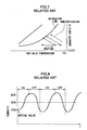
Fig. 8 , the humidifier is turned ON, and humidification is performed in large amounts. As a result, the humidity of outlet air largely exceeds 50%, and thus, the humidifier is turned OFF. Soon after a short period of time, the humidity around the dew-point meter returns to 40% that is the humidity of outside air, and the humidifier is turned ON again. As described above, in the intermediate season in which a difference between the target humidity and the humidity of outside air is small, the humidifier is alternately turned ON/OFF with frequency as shown inFig. 8 , and the humidifier is thereby unnecessarily operated, which is not preferable. - As a first solution to solve the problem, the sensor sensitivity of the control valve of the humidifier may be lowered. Accordingly, the humidifier is not turned ON even if the humidity is low to a certain extent, so that the humidity value is prevented from fluctuating up and down due to the ON/OFF control.
- However, in the case of the first solution, once the humidifier is turned ON, humidification is performed in substantial amounts. Thus, the control cannot be considered as appropriate control.
- On the other hand, as a second solution, a method of excessively heating the inlet air (outside air) more than normal first, humidifying the air, and subsequently, dehumidifying and cooling the humidified high-temperature air by the cooling coil, so as to control the air to have the target humidity may be employed as shown in a psychrometric chart in
Fig. 9 . According to the control method, there is such an advantage that accurate control is enabled since the control by cooling is easier than the control by heating and humidification. - However, the second solution has such a disadvantage that the running cost is increased since a great deal of energy is required for the excess heating.
- The present invention has been made in view of such circumstances, and it is an object of the present invention to provide an evaporative humidifier capable of accurately performing humidity control without unnecessarily operating a humidifying device and without wasting energy.
- In order to achieve the above object, the present invention provides an evaporative humidifier which humidifies air by allowing the air to pass through a humidifying element of a humidifying device, characterized in that the humidifying element is divided into a plurality of humidifying modules via a partition member, a water supply device with a valve is provided in each of the divided humidifying modules, and a control device controls opening and closing of the valve with respect to each valve.
- In the present invention, a desired humidity is obtained by supplying water only to a humidifying module required for humidification. Air simply passes through a humidifying module to which water is not supplied. Accordingly, air obtained by mixing humidified air passing through the humidifying module which is wet with water being supplied thereto (wet zone) and non-humidified air passing through the humidifying module to which water is not supplied (dry zone) is blown out from an outlet of the evaporative humidifier. The mixture amount (mixture ratio) is controlled by the opening and closing of the valve, so that a desired humidity is obtained. Therefore, with the evaporative humidifier of the present invention, humidity control can be accurately performed without unnecessarily operating the humidifying device and without wasting energy.
- Also, according to the present invention, the humidifying element is preferably formed into a rectangular shape in section so as to have the same thickness with respect to an air passing direction, or into a substantially triangular shape in section so as to have a gradually changing thickness with respect to the air passing direction.
- With the present invention, by forming the humidifying element into the rectangular shape in section, the humidity proportionally rises or falls in accordance with the number of humidifying modules to which water is supplied. Also, by forming the humidifying element into the substantially triangular shape in section, the humidity rises or falls in a curve in accordance with the number of humidifying modules to which water is supplied. The humidifying elements are selected according to a humidity environment of outside air introduced into the evaporative humidifier.
- Furthermore, according to the present invention, a dew-point detecting device which detects a dew point of the air passing through the humidifying device is preferably provided, wherein the control device controls the opening and closing of the valve with respect to each valve based on the dew point detected by the dew-point detecting device.
- With the present invention, the control device feedback-controls the opening and closing of the valve with respect to each valve based on the dew point detected by the dew-point detecting device, so that a desired humidity can be obtained.
- Moreover, the present invention preferably further comprises a heating/cooling device which heats/cools the air, wherein a heating amount by the heating/cooling device is controlled to obtain air having a desired temperature.
- Accordingly, with the evaporative humidifier of the present invention, the air having a desired temperature and humidity can be supplied into a room.
- As described above, according to the evaporative humidifier of the present invention, humidity control can be accurately performed without unnecessarily operating the humidifier and without wasting energy.
-
-
Fig. 1 is a block diagram showing a configuration of an evaporative humidifier according to an embodiment; -
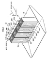
Fig. 2 is a perspective view showing a configuration of a humidifying device according to a first embodiment; -
Fig. 3 is a perspective view showing a configuration of a humidifying device according to a second embodiment; -
Fig. 4 is a perspective view showing a configuration of a humidifying device according to a third embodiment; -
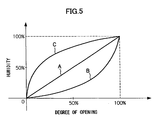
Fig. 5 is a graph showing an increase in humidity relative to a degree of opening of a water supply electromagnetic valve; -
Fig. 6 is a block diagram showing a general configuration of a conventional evaporative humidifier; -
Fig. 7 is a psychrometric chart for explaining one example of a method of controlling a humidification amount in a conventional evaporative humidifier; -
Fig. 8 is a view serially showing ON/OFF of a humidifier when a target humidity is 50%; and -
Fig. 9 is a psychrometric chart for explaining one example of a method of controlling a humidification amount in a conventional evaporative humidifier. - In the following, preferable embodiments of an evaporative humidifier according to the present invention will be described in detail with reference to the accompanying drawings.
-
Fig. 1 is a block diagram showing a configuration of anevaporative humidifier 10 according to an embodiment. - The
evaporative humidifier 10 shown inFig. 1 includes ahumidification flow path 12 formed by a housing case. Anair inlet 14 for introducing outside air and anair outlet 16 for discharging conditioned air whose temperature and humidity are regulated into a room are formed at the ends of thehumidification flow path 12. A cooling/heating coil 18 is provided on the upstream side of thehumidification flow path 12. Air (outside air) flowing in thehumidification flow path 12 is cooled or heated to a desired temperature by a cooling/heating medium supplied to the cooling/heating coil 18. - A
thermometer 20 is provided on the downstream side of thehumidification flow path 12 from the cooling/heating coil 18. The temperature of air passing through the cooling/heating coil 18 is measured by thethermometer 20. The amount or temperature of the cooling/heating medium to be supplied to the cooling/heating coil 18 is feedback-controlled by an unillustrated control device based on the measured air temperature. Ahumidifying device 22 according to a first embodiment is provided on the downstream side of thehumidification flow path 12 from thethermometer 20. Also, a dew-point meter (dew-point detecting device) 24 is provided on the downstream side of thehumidification flow path 12 from thehumidifying device 22. - A
humidifying element 26 which constitutes thehumidifying device 22 according to the first embodiment is disposed in a direction perpendicular to a flow direction A of the introduced outside air as shown inFig. 2 . Thehumidifying element 26 is formed into a rectangular shape in section along the outside air flow direction A, and has the same thickness over the entire area. Furthermore, thehumidifying element 26 is divided in the vertical direction into fourhumidifying modules adjacent humidifying modules 26A to 26D are divided by separators (partition members) 28, so that water does not enter from theadjacent humidifying modules 26A to 26D. The division number of thehumidifying element 26 is not limited to four, and thehumidifying element 26 may be divided into two or more humidifying modules. However, by dividing thehumidifying element 26 into a plurality of humidifying modules, humidity control described below will be precisely performed. - A
water supply unit 30 which constitutes thehumidifying device 22 includes fournozzles humidifying modules humidifying modules 26A to 26D get wet by allowing water to seep from thenozzles 30A to 30D, and air flowing in thehumidification flow path 12 is allowed to pass through thehumidifying modules 26A to 26D, so as to perform humidification. Extra water dropping from thehumidifying modules 26A to 26D is collected in adrain pan 32 located below thehumidifying element 26. - In a
water supply pipe 31 on which thenozzles 30A to 30D of thewater supply unit 30 are provided, water supply electromagnetic valves (valves) 34A, 34B, 34C, and 34D are provided corresponding to thenozzles electromagnetic valve 34A on the upstream side is opened in response to water supply, water is supplied to thehumidifying module 26A from thenozzle 30A. When the water supplyelectromagnetic valves humidifying modules nozzles electromagnetic valves 34A to 34C are opened, water is supplied to thehumidifying modules 26A to 26C from thenozzles 30A to 30C, and when the water supplyelectromagnetic valves 34A to 34D are opened, water is supplied to thehumidifying modules 26A to 26D from thenozzles 30A to 30D. In other words, by controlling the opening and closing of the water supplyelectromagnetic valves 34A to 34D, the humidifying module to which water is to be supplied is selected from thehumidifying modules 26A to 26D. Accordingly, the humidifying module which gets wet with water (wet zone) and the humidifying module to which water is not supplied (dry zone) are formed in onehumidifying element 26. - On the other hand, the opening and closing of the water supply
electromagnetic valves 34A to 34D is controlled by avalve control unit 36 shown inFig. 1 . Thevalve control unit 36 controls the opening and closing of the water supplyelectromagnetic valves 34A to 34D such that a desired humidity is obtained based on a dew point detected by the dew-point meter 24. - That is, in the
evaporative humidifier 10 according to the embodiment, a desired humidity is obtained by supplying water only to the humidifying module required for humidification in thehumidifying element 26. Air simply passes through the humidifying module to which water is not supplied. Therefore, air obtained by mixing humidified air passing through the humidifying module which gets wet with water being supplied thereto (wet zone) and non-humidified air passing through the humidifying module to which water is not supplied (dry zone) is blown out from theoutlet 16 of theevaporative humidifier 10. The mixture amount (mixture ratio) is controlled by the opening and closing of the water supplyelectromagnetic valves 34A to 34D, so as to obtain a desired humidity. To be more specific, thevalve control unit 36 feedback-controls the opening and closing of each of the water supplyelectromagnetic valves 34A to 34D based on the dew point detected by the dew-point meter 24, so that a desired humidity can be obtained. - As described above, according to the
evaporative humidifier 10 of the embodiment, thehumidifying device 22 maintains a stable ON state to perform humidity regulation. Therefore, thehumidifying device 22 is not unnecessarily operated in comparison with a humidifying device which is frequently turned ON/OFF as in a conventional case, and energy is not wasted since excess heating by the cooling/heating coil 18 is not required. Since the mixture ratio of the humidified air and non-humidified air is controlled to perform humidity regulation, humidity control can be accurately performed. - Also, according to the
evaporative humidifier 10 of the embodiment, the amount or temperature of the cooling/heating medium to be supplied to the cooling/heating coil 18 is controlled by the unillustrated control device based on the air temperature measured by thethermometer 20 such that the air has a desired temperature. Accordingly, the air having a desired temperature and humidity can be supplied into a room according to theevaporative humidifier 10. -
Fig. 3 andFig. 4 respectively show ahumidifying device 122 according to a second embodiment, and ahumidifying device 222 according to a third embodiment. -
Humidifying elements humidifying devices - The
humidifying element 126 shown inFig. 3 is formed to become gradually thicker from the upstream side to the downstream side in a water supply direction. Thehumidifying element 226 shown inFig. 4 is formed to become gradually thinner from the upstream side to the downstream side in the water supply direction. - The
humidifying element 126 shown inFig. 3 is divided in the vertical direction into threehumidifying modules adjacent humidifying modules 126A to 126C are divided byseparators 128. Also, thehumidifying element 226 shown inFig. 4 is divided in the vertical direction into sixhumidifying modules adjacent humidifying modules 226A to 226F are divided byseparators 228. The division numbers of thehumidifying elements - A
water supply unit 130 of thehumidifying device 122 inFig. 3 includes threewater supply pipes 133 coupled to amain pipe 131. A plurality of injection holes (not shown) are formed in the bottom portions of thewater supply pipes 133 such that water is injected from the injection holes to thehumidifying modules 126A to 126C. Also, a single water supplyelectromagnetic valve 134A is provided at the base portion of thewater supply pipes 133. Water supplyelectromagnetic valves 134B are respectively provided on the upstream sides of thewater supply pipes 133, and water supply electromagnetic valves 134C are respectively provided on the downstream sides of thewater supply pipes 133. - Therefore, when the water supply
electromagnetic valve 134A is opened, water is injected from the injection holes formed in the respectivewater supply pipes 133 between the water supplyelectromagnetic valve 134A and the respective water supplyelectromagnetic valves 134B, and water is thereby supplied to thehumidifying module 126A of thehumidifying element 122. When the water supplyelectromagnetic valve 134A and the respective water supplyelectromagnetic valves 134B are opened, water is injected from the injection holes formed in the respectivewater supply pipes 133 between the water supplyelectromagnetic valve 134A and the respective water supply electromagnetic valves 134C, and water is thereby supplied to thehumidifying modules humidifying element 122. Furthermore, when the water supplyelectromagnetic valve 134A, the respective water supplyelectromagnetic valves 134B and the respective water supply electromagnetic valves 134C are opened, water is injected from the injection holes formed in all thewater supply pipes 133, and water is thereby supplied to thehumidifying modules 126A to 126C of thehumidifying element 122. That is, by controlling the opening and closing of the water supplyelectromagnetic valves 134A to 134C, the humidifying module to which water is to be supplied is selected from thehumidifying modules 126A to 126C. Accordingly, the humidifying module which gets wet with water (wet zone) and the humidifying module to which water is not supplied (dry zone) are formed in onehumidifying element 126. The opening and closing of the water supplyelectromagnetic valves 134A to 134C is controlled by a valve control unit (not shown inFig. 3 ) in a similar manner toFig. 1 . The valve control unit controls the opening and closing of the water supplyelectromagnetic valves 134A to 134C based on the dew point detected by the dew-point meter 24 such that a desired humidity is obtained in a similar manner toFig. 1 . In thehumidifying device 122 according to the second embodiment, water is also supplied only to the humidifying module required for humidification in thehumidifying element 126, so as to obtain a desired humidity. - A
water supply unit 230 of thehumidifying device 222 inFig. 4 includes aconical pipe 231 havinginjection holes 231 A formed in its bottom portion. Water is injected from the injection holes 231A to thehumidifying modules 226A to 226F. Also, water supplyelectromagnetic valves conical pipe 231. The water supplyelectromagnetic valves 234A to 234F are located at positions corresponding to thehumidifying modules 226A to 226F as described below. - That is, when the water supply
electromagnetic valve 234A is opened, water is injected from theinjection holes 231A formed in theconical pipe 231 between the water supplyelectromagnetic valve 234A and the water supplyelectromagnetic valve 234B, and water is thereby supplied to thehumidifying module 226A of thehumidifying element 222. When the water supplyelectromagnetic valves electromagnetic valve 234A and the water supplyelectromagnetic valve 234C, and water is thereby supplied to thehumidifying modules electromagnetic valves 234A to 234C are opened, water is injected from the injection holes 231A between the water supplyelectromagnetic valve 234A and the water supplyelectromagnetic valve 234D, and water is thereby supplied to thehumidifying modules 226A to 226C. Similarly, when the water supplyelectromagnetic valves 234A to 234D are opened, water is injected from the injection holes 231A between the water supplyelectromagnetic valve 234A and the water supply electromagnetic valve 234E, and water is thereby supplied to thehumidifying modules 226A to 226D, and when the water supplyelectromagnetic valves 234A to 234E are opened, water is injected from the injection holes 231A between the water supplyelectromagnetic valve 234A and the water supplyelectromagnetic valve 234F, and water is thereby supplied to thehumidifying modules 226A to 226E. Finally, when all the water supplyelectromagnetic valves 234A to 234F are opened, water is injected from all the injection holes 231A of theconical pipe 231, and water is thereby supplied to thehumidifying modules 226A to 226F. - That is, by controlling the opening and closing of the water supply
electromagnetic valves 234A to 234F, the humidifying module to which water is to be supplied is selected from thehumidifying modules 226A to 226F. Accordingly, the humidifying module which gets wet with water (wet zone) and the humidifying module to which water is not supplied (dry zone) are formed in onehumidifying element 226. The opening and closing of the water supplyelectromagnetic valves 234A to 234F is controlled by a valve control unit (not shown inFig. 4 ) in a similar manner toFig. 1 . The valve control unit controls the opening and closing of the water supplyelectromagnetic valves 234A to 234F based on the dew point detected by the dew-point meter 24 such that a desired humidity is obtained in a similar manner toFig. 1 . In thehumidifying device 222 according to the third embodiment, water is also supplied only to the humidifying module required for humidification in thehumidifying element 226, so as to obtain a desired humidity. - Next, a graph shown in
Fig. 5 will be described. - In the graph, the vertical axis represents a humidity around the outlet, and the horizontal axis represents a degree of opening of the water supply electromagnetic valve that is opened. To describe the degree of opening with reference to the
humidifying element 26 including the four water supplyelectromagnetic valves 34A to 34D shown inFig. 2 , for example, the degree of opening is 25% when only the water supplyelectromagnetic valve 34A is opened, 50% when the water supplyelectromagnetic valves electromagnetic valves 34A to 34C are opened, and 100% when all the water supplyelectromagnetic valves 34A to 34D are opened. - The line A in the graph represents the
humidifying element 26 shown inFig. 2 , the line B thehumidifying element 126 shown inFig. 3 , and the line C thehumidifying element 226 shown inFig. 4 . - Since the
humidifying element 26 shown inFig. 2 has the uniform thickness, the degree of opening is directly reflected in a surface area ratio of the wet and non-wet humidifying modules, and the ratio is reflected as the humidity of the outlet. Therefore, the rate of humidity increase rises in proportion to the degree of opening in comparison with thehumidifying elements Figs. 3 and4 . - On the other hand, the increases in the
humidifying elements Figs. 3 and4 are changed in a curve as in the lines B and C due to a difference in the thickness of the humidifying module. For example, in the case of thehumidifying element 126 inFig. 3 , when the degree of opening is small, a small amount of low-humidity air passing through the wet zone and a large amount of air passing through the dry zone are mixed, so that the air has a low humidity. As the degree of opening is larger, the thickness of thehumidifying element 126 is larger, and the air has a higher humidity. In the case of thehumidifying element 226 inFig. 4 , an effect opposite to that of thehumidifying element 126 inFig. 3 is obtained. - In the case of the
humidifying element 26 inFig. 2 , the humidity can be proportionally and gradually controlled by reducing the size of the evaporative humidifier. Also, since the amount of water used is decreased, the running cost can be also reduced. - Also, according to the
humidifying elements Figs. 3 and4 , the humidity can be proportionally and gradually controlled in a more compact and accurate manner than thehumidifying element 26 inFig. 2 . Thehumidifying element 126 inFig. 3 is useful in a case where the evaporative humidifier is controlled in an environment in which outside air has a low humidity, and thehumidifying element 226 inFig. 4 is useful in a case where the evaporative humidifier is controlled in an environment in which outside air has a high humidity.
Claims (4)
- An evaporative humidifier (10) which humidifies air by allowing the air to pass through a humidifying element (26, 126, 226) of a humidifying device (22, 122, 222),
characterized in that
the humidifying element (26, 126, 226) is divided into a plurality of humidifying modules (26A-26D, 126A-126C, 226A-226F) via a partition member (28, 128, 228), a water supply device (30, 130, 230) with a valve (34A-34D, 134A-134C, 234A-234F) is provided in each of the divided humidifying modules, and a control device (36) controls opening and closing of the valve with respect to each valve. - The evaporative humidifier (10) according to claim 1, wherein
the humidifying element (26, 126, 226) is formed into a rectangular shape (26A-26D) in section so as to have the same thickness with respect to an air passing direction (A), or into a substantially triangular shape (126A-126C, 226A-226F) in section so as to have a gradually changing thickness with respect to the air passing direction. - The evaporative humidifier (10) according to claim 1 or claim 2, further comprising a dew-point detecting device (24) which detects a dew point of the air passing through the humidifying device (22, 122, 222), wherein
the control device (36)controls the opening and closing of the valve (34A-34D, 134A-134C, 234A-234F) with respect to each valve based on the dew point detected by the dew-point detecting device. - The evaporative humidifier (10) according to any one of claims 1 to 3, further comprising a heating/cooling device (18, 20) which heats/cools the air, wherein
a heating amount by the heating/cooling device is controlled to obtain air having a desired temperature.
Applications Claiming Priority (1)
| Application Number | Priority Date | Filing Date | Title |
|---|---|---|---|
| JP2008054938A JP2009210212A (en) | 2008-03-05 | 2008-03-05 | Evaporative humidifier |
Publications (1)
| Publication Number | Publication Date |
|---|---|
| EP2098794A1 true EP2098794A1 (en) | 2009-09-09 |
Family
ID=40637971
Family Applications (1)
| Application Number | Title | Priority Date | Filing Date |
|---|---|---|---|
| EP20090003121 Withdrawn EP2098794A1 (en) | 2008-03-05 | 2009-03-04 | Evaporative humidifier |
Country Status (3)
| Country | Link |
|---|---|
| US (1) | US20090224414A1 (en) |
| EP (1) | EP2098794A1 (en) |
| JP (1) | JP2009210212A (en) |
Cited By (2)
| Publication number | Priority date | Publication date | Assignee | Title |
|---|---|---|---|---|
| CN102444946A (en) * | 2011-11-18 | 2012-05-09 | 友达光电股份有限公司 | humidity control system |
| CN116085893A (en) * | 2023-02-21 | 2023-05-09 | 珠海格力电器股份有限公司 | Control method and device of fog-free humidifier, storage medium and fog-free humidifier |
Families Citing this family (4)
| Publication number | Priority date | Publication date | Assignee | Title |
|---|---|---|---|---|
| JP7089908B2 (en) * | 2018-03-08 | 2022-06-23 | 東洋熱工業株式会社 | Humidifier control method and humidification system |
| GB201900016D0 (en) * | 2019-01-02 | 2019-02-13 | Dyson Technology Ltd | Air treatment apparatus |
| GB201900022D0 (en) * | 2019-01-02 | 2019-02-13 | Dyson Technology Ltd | Air treatment apparatus |
| CN113757836A (en) * | 2020-06-01 | 2021-12-07 | 深圳市联创科技集团有限公司 | Air-conditioning fan |
Citations (5)
| Publication number | Priority date | Publication date | Assignee | Title |
|---|---|---|---|---|
| DE2237852A1 (en) * | 1972-08-01 | 1974-02-14 | Siemens Ag | PROCESS AND DEVICE FOR THE AIR-SIDE CONTROL OF VENTILATION SYSTEMS |
| JPH028642A (en) | 1988-06-25 | 1990-01-12 | Taikisha Ltd | Humidifier |
| JPH04136641A (en) * | 1990-09-27 | 1992-05-11 | P S Kogyo Kk | Evaporative humidifier and humidifying system using the same |
| JP2001317795A (en) * | 2000-05-09 | 2001-11-16 | Techno Ryowa Ltd | Air conditioner and humidity control method |
| JP2006162167A (en) * | 2004-12-08 | 2006-06-22 | Wetmaster Co Ltd | Humidifier |
Family Cites Families (5)
| Publication number | Priority date | Publication date | Assignee | Title |
|---|---|---|---|---|
| US4494596A (en) * | 1980-05-16 | 1985-01-22 | Haden Schweitzer Corporation | Method and apparatus for conditioning air temperature and humidity |
| US4940475A (en) * | 1989-09-26 | 1990-07-10 | Yaeger Ronald J | Variable capacity evaporative humidifier |
| US5620503A (en) * | 1993-11-04 | 1997-04-15 | Tom Miller, Inc. | Humidifier and method for humidifying air |
| US6129285A (en) * | 1998-08-11 | 2000-10-10 | Schafka; Mark Louis | System and method for air humidification |
| JP4989031B2 (en) * | 2005-03-18 | 2012-08-01 | 日本ゴア株式会社 | Humidifier and draining method of humidifying element |
-
2008
- 2008-03-05 JP JP2008054938A patent/JP2009210212A/en not_active Withdrawn
-
2009
- 2009-03-02 US US12/396,070 patent/US20090224414A1/en not_active Abandoned
- 2009-03-04 EP EP20090003121 patent/EP2098794A1/en not_active Withdrawn
Patent Citations (5)
| Publication number | Priority date | Publication date | Assignee | Title |
|---|---|---|---|---|
| DE2237852A1 (en) * | 1972-08-01 | 1974-02-14 | Siemens Ag | PROCESS AND DEVICE FOR THE AIR-SIDE CONTROL OF VENTILATION SYSTEMS |
| JPH028642A (en) | 1988-06-25 | 1990-01-12 | Taikisha Ltd | Humidifier |
| JPH04136641A (en) * | 1990-09-27 | 1992-05-11 | P S Kogyo Kk | Evaporative humidifier and humidifying system using the same |
| JP2001317795A (en) * | 2000-05-09 | 2001-11-16 | Techno Ryowa Ltd | Air conditioner and humidity control method |
| JP2006162167A (en) * | 2004-12-08 | 2006-06-22 | Wetmaster Co Ltd | Humidifier |
Cited By (2)
| Publication number | Priority date | Publication date | Assignee | Title |
|---|---|---|---|---|
| CN102444946A (en) * | 2011-11-18 | 2012-05-09 | 友达光电股份有限公司 | humidity control system |
| CN116085893A (en) * | 2023-02-21 | 2023-05-09 | 珠海格力电器股份有限公司 | Control method and device of fog-free humidifier, storage medium and fog-free humidifier |
Also Published As
| Publication number | Publication date |
|---|---|
| JP2009210212A (en) | 2009-09-17 |
| US20090224414A1 (en) | 2009-09-10 |
Similar Documents
| Publication | Publication Date | Title |
|---|---|---|
| EP2098794A1 (en) | Evaporative humidifier | |
| AU2022263511B2 (en) | Direct Evaporative Cooling System with precise temperature control | |
| US9743559B2 (en) | Apparatus and method for cooling server room using outside air | |
| US20120055273A1 (en) | Dew formation testing device and dew formation testing method | |
| DK172000B1 (en) | Mixing section for supply air and return air in an air conditioner | |
| US10545476B2 (en) | Method of self-balancing plurality of mechanical components within a temperature control unit of an HVAC system | |
| US10837658B2 (en) | Air conditioner | |
| JP3942820B2 (en) | Humidification method for air conditioning | |
| US10866009B2 (en) | Air conditioning system regulating temperature and humidity of air | |
| US11137149B2 (en) | Device and method for controlling a supply air flow at a comfort cassette | |
| JP2009210167A (en) | Evaporative humidifier | |
| KR102424071B1 (en) | Ventilation system and controlling method thereof | |
| KR102302343B1 (en) | air conditioner | |
| KR101659317B1 (en) | Apparutus for supplying fluid and substrate process system having the same | |
| JP4948070B2 (en) | Air conditioning control method and air conditioner | |
| EP4441437B1 (en) | Air conditioner including a plurality of evaporative cooling units | |
| KR101609126B1 (en) | Air conditioning system and method of conditioning air using the same system | |
| CN119222644A (en) | Humidity control system and control method of humidity control system | |
| JP7089908B2 (en) | Humidifier control method and humidification system | |
| JPH081392Y2 (en) | Humidity control device | |
| JP2024506072A (en) | Membrane contactor-based air conditioner | |
| JP2023132462A (en) | air conditioning system | |
| JPH02217733A (en) | Humidifier | |
| JPH05296534A (en) | Humidity control device for air conditioning equipment | |
| HU185339B (en) | Method for adjusting air-conditioning systems, preferably flat ventillation systems |
Legal Events
| Date | Code | Title | Description |
|---|---|---|---|
| PUAI | Public reference made under article 153(3) epc to a published international application that has entered the european phase |
Free format text: ORIGINAL CODE: 0009012 |
|
| AK | Designated contracting states |
Kind code of ref document: A1 Designated state(s): AT BE BG CH CY CZ DE DK EE ES FI FR GB GR HR HU IE IS IT LI LT LU LV MC MK MT NL NO PL PT RO SE SI SK TR |
|
| AX | Request for extension of the european patent |
Extension state: AL BA RS |
|
| 17P | Request for examination filed |
Effective date: 20091123 |
|
| AKX | Designation fees paid |
Designated state(s): CH DE FR GB LI |
|
| RAP1 | Party data changed (applicant data changed or rights of an application transferred) |
Owner name: HITACHI, LTD. |
|
| GRAP | Despatch of communication of intention to grant a patent |
Free format text: ORIGINAL CODE: EPIDOSNIGR1 |
|
| INTG | Intention to grant announced |
Effective date: 20150518 |
|
| STAA | Information on the status of an ep patent application or granted ep patent |
Free format text: STATUS: THE APPLICATION IS DEEMED TO BE WITHDRAWN |
|
| 18D | Application deemed to be withdrawn |
Effective date: 20150929 |